1
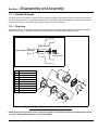
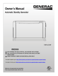
Generator
Disassembly and Assembly
Service Manual
*
*
NOT INTENDED FOR USE IN CRITICAL
LIFE SUPPORT APPLICATIONS.
*
DEADLY EXHAUST FUMES! OUTDOOR
INSTALLATION ONLY!
ONLY QUALIFIED ELECTRICIANS OR
CONTRACTORS SHOULD ATTEMPT
INSTALLATION!
This manual should remain with the unit.
This manual must be used in conjunction
with the appropriate owner’s manual.
WARNING!
California Proposition 65
Engine exhaust and some of its constituents are known to the state of California to cause cancer,
birth defects, and other reproductive harm.
WARNING!
California Proposition 65
This product contains or emits chemicals known to the state of California to cause cancer,
birth defects, and other reproductive harm.
ii
Generator Service Manual
Table of Contents
Section 1 Disassembly and Assembly
1.1 Intended Purpose ................................................................................................................. 1
1.2 Overview ............................................................................................................................... 1
1.3 Disassembly Hints ............................................................................................................... 2
1.3.1 Stator Disassembly .................................................................................................................................... 2
1.3.2 Rotor Disassembly ..................................................................................................................................... 2
1.4 Assembly Hints .................................................................................................................... 2
1.4.1 Adapter Installation .................................................................................................................................... 2
1.4.2 Rotor and Fan Assembly ........................................................................................................................... 2
1.4.3 Stator Installation ....................................................................................................................................... 3
1.4.4 Bearing Bracket Installation ...................................................................................................................... 3
1.4.5 Outlet Cover Installation ............................................................................................................................ 3
Generator Service Manual
iii
Table of Contents
This page intentionally left blank.
iv
Generator Service Manual
Section 1
Disassembly and Assembly
1.1 — Intended Purpose
This quick guide is not intended to replace service training programs or information covered in specific product manuals. It is merely a guide for an experienced individual who is already qualified and experienced in servicing generator
sets. This document is not meant to replace other service training or procedures.
1.2 — Overview
The insert of Figure 1-1 shows the adapter face as viewed from the engine output shaft and how the rotor assembly
attaches to the engine crankshaft. The bottom illustration shows the disassembly/assembly process.
Rotor Assembly
Tapered Engine Crankshaft
C-Washer
and Cap Screw
Item
5
Description
1
Adapter (4 Cap Screws)
2
Fan
3
Rotor
4
Bearing
5
Stator
6
Bearing Bracket
7
End Plate
8
C-Washer and Cap Screw
9
Stator Bolts
6
9
1
8
7
2
3
4
Figure 1-1. Typical Generator Assembly and Components
NOTE: Engine driven generator sets are subject to vibration. Consequently all fasteners should employ a locking device. Split type lock washers are generally suitable.
Generator Service Manual
1
Disassembly and Assembly
1.3 — Disassembly Hints
See Figure 1-1.
During disassembly, note the routing of the wire leads for the outlet cover and the method of securing the leads. Upon
reassembly, the leads must be reinstalled and secured as they were.
CAUTION: Damage to the molded bearing support or slip-ring assembly requires that the complete rotor
assembly be replaced.
1.3.1— Stator Disassembly
The entire stator, bearing bracket and outlet box may be removed as an assembly. Open the control box cover and
remove the collector ring brushes, if applicable. Remove the four stator bolts and fasteners used to secure the bearing
bracket to the adapter. Tap the bearing bracket at the stator bolt holes to release from the stator shell. Now the stator
assembly may be slid from the engine adapter casting by a gentle prying action between stator shell and engine
adapter castings.
1.3.2— Rotor Disassembly
Loosen the rotor bolt a few turns using a thin wall 1/2 inch wrench. Remove the C-washer. The rotor can be removed
from the engine crankshaft (rotor bolt does not have to be removed completely).
1.4 — Assembly Hints
See Figure 1-1.
NOTE: Before assembly, check adapter and engine shaft pilot surface fit. Be sure all machined surfaces are
clean, free of burrs and damage.
1.4.1— Adapter Installation
1.
Clean the engine shaft and pilot surface thoroughly.
2.
Place the adapter on engine pilot surface.
3.
There should be no observable left/right, up/down movement.
4.
If the adapter does not fit snug to the pilot, replace the adapter.
5.
Mount the adapter with four hex cap screws, tightening in a diagonal fashion to prevent adapter warpage.
1.4.2— Rotor and Fan Assembly
The rotor assembly mounts directly to the end of the tapered engine crankshaft.
NOTE: Before assembly, if the rotor, stator or bearing bracket has sustained any mechanical damage replace
all parts (not just one damaged item).
1.
Install a 5/16-24 x 3/4 inch NF hex head cap screw into the end of the engine crankshaft. Turn the cap screw
approximately 3/8 inch into engine shaft. The C-washer will be installed after the rotor is on the crankshaft.
2.
Slip the rotor fully onto the engine crankshaft. The cap screw extends through the rotor flange.
3.
Slide the C-washer between the bolt head and the engine shaft, see Figure 1-1.
4.
Tighten the cap screw with a thin wall 1/2 inch wrench.
NOTE: Two-bearing generators have permanently attached drive end castings. Bearing replacement should
only be performed by authorized personnel. Consult Factory Service Department at 1-800-872-7697.
CAUTION: Damage to the molded bearing support or slip-ring assembly requires that the complete rotor
assembly be replaced.
2
Generator Service Manual
Disassembly and Assembly
1.4.3— Stator Installation
1.
With stator shell seam down, slip stator over the rotor onto engine adapter.
2.
Seat the rotor to the adapter using rawhide-covered mallet.
1.4.4— Bearing Bracket Installation
CAUTION: These steps must be followed exactly as written to prevent damage.
1.
The outboard bearing bracket must be assembled to the stator in the following manner:
a. The bracket web assembles the letter “Y.” The vertical portion of the “Y” must be positioned at the bottom of
the bracket.
b. Align bracket stub shaft with the rotor bearing inner race bore. Bearing bracket pilot must be aligned with the
stator housing.
c. Carefully and lightly tap on bracket, CENTER ONLY, until the bracket is seated on the stator shell. Any pressure or tapping on the bracket, other than in the center, can fracture the molded bearing support and slip ring
assembly on the rotor.
2.
Secure with stator bolts. The stator bolt holes must line up on the bearing bracket and adapter holes.
3.
If applicable, inspect the brushes and replace them if worn to 1/2 inch or less.
4.
If applicable, insert the brushes and tighten brush caps finger-tight. Be sure brushes work freely in holders.
1.4.5— Outlet Cover Installation
CAUTION: If wires are not bundled and properly secured before the cover is installed, the wires may come in
contact with the rotor and be damaged.
When reinstalling cover, ensure no wires are or will be pinched when the cover is installed. The wires must be bundled
and secured using wire ties as they were before disassembly.
1.
Verify all wires are placed properly and secured with wire ties to prevent damage.
2.
Install cover to bearing bracket using small screws.
NOTE: If the duplex 120 volt receptacle is replaced, observe the terminal on the ground side (gold color). The
duplex tab may have been split into individual receptacles by removal of this connecting tab. If the tab has
been removed, the tab on the replacement receptacle must also be removed to ensure the outlets remain isolated.
Generator Service Manual
3
Disassembly and Assembly
This page intentionally left blank.
4
Generator Service Manual
Part No. MN2404 Rev. A 01/28/2014 Printed in USA
© Generac Power Systems, Inc. All rights reserved
Specifications are subject to change without notice.
No reproduction allowed in any form without prior written
consent from Generac Power Systems, Inc.
Generac Power Systems, Inc.
S45 W29290 Hwy. 59
Waukesha, WI 53189
1-888-GENERAC (1-888-436-3722)
generac.com