1
Manual No, A9!95
OWNER•s MANUAL
and Installation Instructions
IMPACT-36 plus with Inverter
AIR-COOLED
RE REATI N
HI LE
ENERAT R
Model Nos. 00940-1,00941-1
GENERAC®
POWER SYSTEMS, INC.
Revision 3 (01/28/00)
Printed in U5A
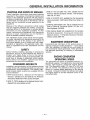
GENERAL SAFETY RULES
THE MANUFACTURER SUGGESTS THAT THESE "RULES" FOR SAFE OPERATION BE[!]
COPIED AND POSTED IN POTENTIAL HAZARD AREAS OF THE RECREATIONAL VEHICLE.
A
SAFETY SHOULD BE STRESSED TO ALL OPERATORS AND POTENTIAL OPERATORS OF ~
THIS EQUIPMENT.
Study these SAFETY RULES carefully before operating or servicing applicable equipment. Become familiar
with this Owner's Manual and with your generator.
Safe, efficient and reliable operation can only be
achieved if generator is properly installed, operated
and maintained. Many accidents are caused by failing
to follow simple and fundamental rules or precautions.
The manufacturer suggests that these GENERAL
SAFETY RULES be copied and posted in potential
hazard areas of the recreational vehicle. Safety should
be stressed to all operators and potential operators of
equipment.
The manufacturer cannot possibly anticipate every circumstance that might involve a hazard. The warnings
in this manual and on tags and decals affixed to the
unit are, therefore, not all-inclusive. If you use a procedure, work method or operating technique Generac
does not specifically recommend, you must satisfy
yourself that it is safe for you and others. You must
also make sure the procedure, work method or operating technique that you chose does not render the generator to be unsafe.
The engine exhaust from this product
contains chemicals known to the State
of California to cause cancer, birth
defects or other re roductive harm.
A For fire safety, the recreational vehicle generator
ll8 must be properly installed and maintained.
Installation must always remain in compliance with
applicable codes and standards. In addition, the
generator must be installed in conformance to the
manufacturer's detailed installation instructions.
Following installation, nothing must be done that
might render the generator in noncompliance with
such codes, standards and instructions.
A The RV generator produces extremely high and
~dangerous electrica voltages and can cause dangerous, and possibly fatal, electrical shock. Avoid
contact with bare wires, terminals, etc. while the
unit is running. If you must work around an operating generator, stand on an insulated, dry surface
to reduce shock hazard.
• Never work on this equipment or handle any electrical device while standing in water, while barefoot, or while hands or feet are wet. Dangerous
electrical shock will result.
• Have the generator properly grounded (bonded)
during installation onto the vehicle, either by solid
mounting to the vehicle frame or chassis or by
means of an approved bonding conductor. DO
NOT disconnect the bonding conductor, if so
equipped. DO NOT reconnect the bonding conductor to any generator part that might be
removed or disassembled during routine maintenance. If the grounding conductor must be
replaced, use only a flexible conductor that is of
No. 8 AWG copper wire minimum.
•
!n case of accident caused by electric shock, shut down
the source of electrical power down at once. If this cannot be done, free victim from live conductor. AVOID
DIRECT CONTACT WITH THE VICTIM. Use a dry
board, dry rope, or other non-conducting implement to
free the victim from live conductor. Apply first aid and
get medical help.
A Inspect fuel system frequently for leaks or damage.
~Repair or replace any damaged or leaking component immediately. Never attempt to change, alter
or modify the generator fuel system in any way that
might affect safety or compliance with applicable
codes and standards.
• The generator engine gives off DEADLY carbon
monoxide gas through its exhaust system. This
dangerous gas, if breathed in sufficient concentrations, can cause unconsciousness or even death.
This exhaust system must have been properly
installed, in strict compliance with applicable codes
and standards. Following installation, you must do
nothing that might render the system unsafe or in
non-compliance with such codes and standards.
The generator compartment must be completely
vapor sealed from vehicle interior. There must be
no possibility of exhaust fumes entering the vehicle interior. Never operate this equipment with a
leaking or defective exhaust system.
• Never use the generator or any of its parts as a
step. Stepping on the unit can stress and break
parts and may result in dangerous, fuel leakage,
oil leakage, etc.
!A Do not smoke around the generator. Wipe up any
t.m fuel and oil spills immediately. Never leave oily or
fuel soaked rags in the generator compartment or
on the generator itself. Keep the area around the
generator clean and free of debris.
Adequate ventilation is required to expel toxic
fumes and fuel vapors from the generator compartment. Do not alter the installation of this equipment in any manner that might obstruct air and
ventilation openings. Such openings must be kept
clear and unobstructed.
• Keep hands, feet, clothing, etc., away from drive
belts, fans and other moving parts of this equipment. Never remove any drive belt or fan guards
while the unit is operating.
• Inspect the generator periodically. Repair or replace
all damaged or defective parts immediately.
A These generators can be converted to use LP gas
A. (propane) as a fuel. Liquid Propane gas is highly
EXPLOSIVE. The gas is heavier than air and
tends to settle in low areas where even the slighte~t spark can ignite the gas and cause an exploSion.
A Before performing any maintenknce on the gener.M.ator set, disconnect its battery cables to prevent
accidental start up. Disconnect the cable from the
battery post indicated by a NEGATIVE, NEG or(-)
first. Reconnect that cable last.
A
TABLE OF CONTENTS
OPERATING INSTRUCTIONS
GENERAL SAFETY RULES ......................... .inside cover
IDENTIFICATION RECORD ......................................... 2-3
GENERATOR and INVERTER FEATURES ................ 2-4
READ THIS MANUAL THOROUGHLY
Operation and Maintenance...................................................... 5
How to Obtain Service .. .. .. ... ... .. ... .. ... .. .. ... .. .. .. .. ... .. .. .. .. .. ... .. ... ... . 5
Service Dealer Location ... .. .. .. .. .. .. .. .. .. ... .. .. .... .. .. .. .. .. .. .. ... .. .. .. .. .. . 5
GENERATOR FAMILIARIZATION
Generator Applicability.............................................................. 6
Safety
6
OPERATING INSTRUCTIONS
Generator Control Panel .. ........ ........... .... ... .. .. .. ....... .... .... ... ... .. .. 7
Automatic Choke (Gasoline only) ............................................. 7
Before Starting the Engine ...................................................... 7-8
Starting ...................................................................................... 8
Stopping the Generator............................................................. 8
Applying Loads to Generator .... ................. ............................ ... 8
Attention Required After Submersion .. .... .. .. ..... ..... ................... 8
Operation in High Grass or Brush ............................................. 8
Operating Precautions ............................................................ 8-9
Effects of Moisture and Dirt ....................................................... 9
Do Not Overload the Generator................................................ 9
Equipment Description
16
Engine Generator Operating Speed ........................................ 16
LOCATION AND SUPPORT
Generator Location
Generator Support ...................................................................
Suspended Mounting
Generator Restraint
17
17
17
18
GENERATOR COMPARTMENTS
Compartment Seams ............................................................... 18
Compartment Size ................................................................... 19
Compartment Construction ...................................................... 19
Sound Insulation Materials ....................................................... 19
Compartment Floor Cutouts ..................................................... 20
Acoustics .................................................................................. 20
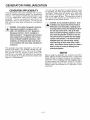
COOLING AND VENTILATION AIR
Generator Air Flow .................................................................. 21
Cooling Air Inlet Openings .................................................. 21-22
22
Compensating for Restrictions
Inverter Location.......................................
............... 22
Testing the Installation ..... .. .. .. ........ .. .. ... ..
....... 22
GASOLINE FUEL SYSTEM
Fuel Tank .............................................. ..
Generator Fuel Supply Line
.. .......... 23
................... 23-24
PROPANE GAS FUEL SYSTEM
ENGINE PROTECTIVE DEVICES
Automatic Low Oil Pressure Shutdown .....................................
High Temperature Shutdown
Overspeed
Low Voltage
9
9
9
9
SPECIFICATIONS
Fuel
10
10
10
10
MAINTENANCE
Checking Engine Oil Level
11
Change Engine Oil
11
Change Oil Filter
11
Engine Air Cleaner .............................................................. 11-12
Clean Air Intake Screen
12
12
Engine Spark Plug
Fuel Filter
2
Inverter ...................................................................................... 12
Cleaning the Generator ............................................................ 12
Battery ...................................................................................... 13
Service and Adjustments ......................................................... 13
Adjusting the Carburetor .......................................................... 13
Adjusting Valve Clearance ....................................................... 13
Major Service Manual .............................................................. 14
Exercising the Generator ......................................................... 14
Out of Service Protection ......................................................... 14
Return the Unit to Service after Storage .................................. 14
Service Dealer Location ........................................................... 14
Parts Not Included in Fuel System ........................................... 24
Some Important Considerations .............................................. 24
Vapor Withdrawal ..................................................................... 24
Primary Regulator ............................................................... 24-25
25
Gaseous Carburetion
Fuel Supply Lines
25
Excess Flow Valve .................................................................. 25
Leakage Tests
25
EXHAUST SYSTEM
Mufflers and Spark Arrestors
26
Type of Exhaust System
26
Exhaust System Safety .......................................................... 26
ELECTRICAL CONNECTIONS
Wiring
Generator AC Connection System ...........................................
Isolating Different Power Sources ............................................
Power Supply Cord
Ground Fault Circuit Interrupters
Sensing Harnesses ..................................................................
Transfer Switch Isolation Method ............................................
Installation with Isolation Receptacle
27
27
27
27
28
28
29
29
BATTERY INSTALLATION ............................................. 30
OPTIONAL ACCESSORIES ........................................... 31
POST INSTALLATION TESTS ....................................... 32
INSTALLATION CHECK LIST ....................................... 33
MAJOR FEATURES AND DIMENSIONS ................. 34-35
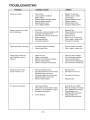
TROUBLESHOOTING .................................................... 36
INSTALLATION SAFETY RULES .................................. 15
NOTES ............................................................................ 37
Notice to Installer ..................................................................... 15
Safety Rules ............................................................................. 15
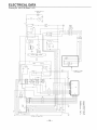
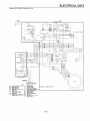
ELECTRICAL DATA ................................................. 38-39
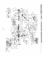
REPAIR PARTS .................................................... 40 to 51
GENERAL INSTALLATION INFORMATION
Purpose and Scope of Manual... .............................................. 16
Safety ....................................................................................... 16
Standards Booklets .................................................................. 16
-1
EMISSIONS WARRANTY ........................................52 - 53
WARRANTY ......................................................back page
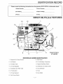
IDENTIFICATION RECORD
Please record the following information from the generator OAT A DECAL or information decal.
1. Model Number_ _ _ _ _ __
2.Serial Number_ _ _ _ _ __
3.kW Rating _ _ _ _ _ _ __
4. Rated Voltage_ _ _ _ _ __
S.Phase_ _ _ _ _ _ _ _ __
6.Hertz_ _ _ _ _ _ _ __
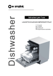
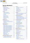
IMPACT-36G plus FEATURES
14
1
3
1
8
IMPACT-36 plus
GASOLINE
7
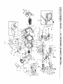
REFERENCE NUMBER IDENTIFICATION
1. Generator Air Intake Screen
8. Data Decal
2. Air Cleaner
9. 12 Volt Battery Connection
3. Air Intake Tube
10. Engine Start/Stop Switch
4. Oil Dipstick and Filler Tube
11 . Generator DC Output Leads
5. Fuel Pump
12. Circuit Breaker
6. Gasoline Carburetor
13. Fuse
7. Fuel Primer Switch
14. Hour Meter
-2-
IDENTIFICATION RECORD
Please record the following information from the generator DATA DECAL or information decal.
1.Model
2.Serial
3.kW
4.Rated
5.
6.
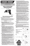
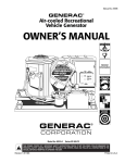
IMPACT-36LPG plus FEATURES
14
1
15
12
4
11
7
8
lmpact-36 plus
LP VAPOR
REFERENCE NUMBER IDENTIFICATION
1. Generator Air Intake Screen
9. Data Decal
2. Air Cleaner
10. 12 Volt Battery Connection
3. Air Intake Tube
11. Engine Start/Stop Switch
4. LP Fuel Regulator
12. Generator DC Output Leads
5. Oil Dipstick and Filler Tube
13. Circuit Breaker
6. LP Carburetor
14. Fuse
7. LP Fuel Solenoid
15 .. Hour Meter
8. Fuel Primer Switch
-3-
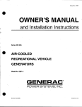
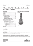
INVERTER FEATURES
2
6
5
PART
REFERENCE NUMBER IDENTIFICATION
1. Inverter
4. 2 Pin Connection
2. 9 Pin Connection
5. DC Input
3. Customer AC Output
6. Cooling Fan
4
READ THIS MANUAL THOROUGHLY
If you do not understand any portion of this manual,
contact Generac or your nearest Generac Authorized
Service Dealer for starting, operating and servicing
procedures.
Throughout this publication and on tags and decals
affixed to the generator, DANGER, WARNiNG, CAUTION and NOTE blocks are used to alert you to special instruction about a particular operation that may
be hazardous if performed incorrectly or carelessly.
Observe them carefully.
These safety warnings cannot eliminate the hazards
that they indicate. Strict compliance with the special
instructions while performing the service plus "common sensei! are major measures to prevent accidents.
The following definitions apply to DANGER WARNING, CAUTION and NOTE blocks found throughout
the manual.
DANGER: After this heading you can read handling, installing, operating or servicing instructions that, if not strictly complied with, will result in
personal injury.
WARNING: After this heading you can read handling, installing, operating or servicing instructions that, if not strictly complied with, may result
in personal injury.
After this heading
can
instructions handling, installing, operating or servicing
the generator that, if not strictly complied with,
could
in
to
NOTE: After this heading you can read explanatory
statements that require special emphasis.
These symbols indicate the following:
~ Points out important safety information and, if
not followed, could endanger personal safety
and/or property of yourself and others.
IAl
IA. I Potential explosion hazard
IA I Potential lire hazard
I~~ Potential electrical shock hazard
The operator (driver) is responsible for proper and
safe use of the vehicle, equipment on the vehicle, and
the safety of all vehicle occupants. We strongly recommend that the operator read this Owner's Manual
and thoroughly understand all instructions before
using this equipment. We also strongly recommend
instructing other occupants in the vehicle to properly
start and operate the generator. This prepares them if
they need to operate the equipment in an emergency.
OPERATION AND MAINTENANCE
It is the operator's responsibility to perform all safety
checks, to make sure that all maintenance for safe
operation is performed promptly, and to have the
equipment checked by an Authorized Dealer periodically. Normal maintenance service and replacement
of parts are the responsibility of the Owner/Operator
and, as such, are not considered defects in materials
or workmanship within the terms of the warranty.
Individual operating habits and usage contribute to
the need for maintenance service.
Proper maintenance and care of your RV generator
assures a minimum number of problems and keeps
your operating expenses at a minimum. See your
authorized Dealer/Distributor for service aids and
accessories.
When your RV generator set requires servicing or
repairs, simply contact an Authorized Service Facility
for assistance. Service technicians are factorytrained and are capable of handling all of your service
needs.
When contacting an Authorized Service Facility or the
factory about parts and service, always supply the
complete model number and serial number of your
unit as given on its data decal.
The warranty on your generator is included in this
Owner's Manual, as well as listings for repair parts.
SERVICE DEALER LOCATION
TO LOCATE THE NEAREST GENERAC SERVICING DEALER, PLEASE CALL OUR 800 NUMBER.
ONLY DEALER LOCATION INFORMATION CAN BE OBTAINED AT THIS NUMBER.
1-800-333-1322
5-
GENERATOR FAMILIARIZATION
GENERATOR APPLICABILITY
These generators have been designed and manufactured for supplying electrical power for recreational
vehicles. You should not modify the generator or use
it for any application other than for \Nhat it was
designed. If there are questions pertaining to its
application, write or call the factory. Do not use the
unit until you have been advised by a competent
authority.
DANGER: For fire safety, the generator must have
been properly installed in compliance with (1)
ANSI119.2-1975/NFPA 501 C-197 4 "Standard for
Recreational Vehicles", Part Ill, "Installation of
Electrical Systems:' The generator also must have
been installed in strict compliance with the manufacturer's detailed installation instructions. After
installation, do nothing that might render the unit
in non-compliance with such codes, standards and
instructions.
This generator has been designed to work with an
inverter (P/N A6187). The inverter changes the voltage from the generator from a DC to an AC vol'tage.
This generator will not operate properly without the
inverter box connected. All repairs of the inverter
must be handled by an authorized service dealer (see
Page 12 in "Maintenance").
-6
You can use this generator to supply electrical povver
for operating 120 volts, single phase, 60 Hertz, electrical loads. These loads can require up to 3400 watts
(3.4 kW) for the lmpact-34 plus, or 3600 watts (3.6
kW) for the lmpact-36 plus. The maximum current at
120 volts is 28.3 amperes for the lmpact-34 plus, or
30 amperes for the lmpact-36 plus.
CAUTION: Do not overload the generator. Some
installations may require that electrical loads be
alternated to avoid overloading. Applying excessively high electrical loads may damage the generator and may shorten its life. Add up the rated
watts of all electrical lighting, appliance, tool and
motor loads the generator will power at one time.
This total should not be greater than the wattage
capacity of the generator. If an electrical device
nameplate gives only volts and amps, multiply
volts times amps to obtain watts (volts x amps =
watts). Some electric motors require more watts of
power (or amps of current) for starting than for
continuous operation.
SAFETY
Before using the generator set, carefully read GENERAL SAFETY RULES inside the cover. Comply with
these RULES to prevent accidents and damage to
equipment and/or property. Generac suggests copying and posting the GENERAL SAFETY RULES in
potential hazard areas of the recreational vehicle.
Safety should be stressed to all operators of this
equipment.
OPERATING INSTRUCTIONS
GENERATOR CONTROL PANEL
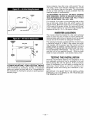
• CHOKE SOlENOID (GASOLINE ONlY)
Mounted on the generator control panel (Figure 1) are
the following features:
During engine cranking (start/stop switch at START),
a solid state control circuit board signals the choke
solenoid to actuate and cycle (choke on/choke off)
until engine starts. The choke solenoid thus opens
and closes the carburetor choke valve only when the
engine is cranking. When the engine starts, the
choke cycling stops .
• PRECHOKE (GASOLINE ONLY)
The choke system also has a temperature sensitive
metal strip that adjusts the choke valve angle according to ambient temperatures (i.e., in cold ambient
temperatures the choke valve closes more). Once
the engine starts, an element heats the temperaturesensitive strip to a normal operating condition, opening the choke valve. This may take about 3 minutes
in cooler weather.
BEFORE STARTING THE ENGINE
• FUEL PRIMER
Before starting a cold engine (if it has not been started in more than two weeks), you must press this
switch to bring fuel from the tank to the fuel carburetor. This rocker type switch springs back into its original position when you release it.
•
SWITCH
To crank and start the engine, hold this switch at its
START position. Release the switch when the engine
starts. To stop an operating engine, press and hold
the switch in its STOP position until the engine shuts
off. The switch center position is the RUN position.
• FUSE
Protects the engine DC control circuit against electrical
overload. If the fuse element has melted open due to
overloading, the engine cannot be cranked. If you must
replace it, use only an identical replacement fuse.
IMPORTANT: INSTRUCTIONS AND INFORMATION
IN THIS MANUAL ASSUME THE GENERATOR HAS
BEEN PROPERLY INSTALLED, CONNECTED,
SERVICED, TESTED AND ADJUSTED BY A QUALIFIED INSTALLATION TECHNICIAN OR INSTALLATION CONTRACTOR.
• INSTALLATION
Generator installation must have been properly completed so it complies with all applicable codes, standards and regulations and with the manufacturer's
recommendations.
• ENGINE LUBRICATION
Have engine crankcase properly serviced with recommended oil before starting. Refer to "Maintenance"
and "Specifications" sections for oil servicing procedures and recommendations.
CAUTION: Any attempt to crank or start the engine
before you have properly serviced it with the recommended oil may result in engine failure .
• CIRCUIT BREAKERS
Protects generator's AC output circuit against overload, i.e., prevents unit from exceeding
wattage/amperage capacity.
• HOUR METER
Indicates the time the engine-generator has operated,
in hours and tenths of hours. Use the hourmeter
along with the periodic maintenance schedule for your
generator set.
AUTOMATIC CHOKE (GASOLINE ONLY)
The engine is equipped with an automatic choke (not
shown) that consists of two main components choke solenoid and prechoke.
• FUEL SUPPLY
The engine must have adequate supply of proper fuel
to operate. Before starting, check that sufficient fuel is
available .
NOTE: On some gasoline installations, the generator
engine may "share" the vehicle's gasoline fuel tank with
the vehicle engine. Some installations may provide
separate fuel tanks for generator and vehicle engine.
• COOLING AND VENTILATING AIR
Air inlet and outlet openings in the generator compartment must be open and unobstructed for continued
proper operation. Without sufficient cooling and ventilating air flow, the engine-generator quickly overheats,
which causes it to automatically shutdown. Overheating
could also damage the unit or your vehicle.
7-
• ENGINE EXHAUST GAS
Before starting the generator engine, you should be
sure there is no way for exhaust gases to enter the
vehicle interior and endangering people or animals.
Close windows, doors and other openings in the vehicle that, if open, might permit exhaust gases to enter
the vehicle.
DANGER: The generator engine gives off deadly
carbon monoxide gas through its exhaust system.
This dangerous gas, if breathed in sufficient con·
centrations, can cause unconsciousness or even
death. Do not operate the generator if its exhaust
system is leaking or has been damaged.
Symptoms of carbon monoxide poisoning are (a)
inability to think coherently, (b) vomiting, (c)
twitching muscles, (d) throbbing temples, (e) dizziness, (f) headache, (g) weakness and sleepiness.
If you feel any of these symptoms, move into fresh
air immediately. If symptoms persist, get medical
help.
STARTING
IMPORTANT: Read the vehicle manufacturer's
instructions. The owner/operator should become
familiar with the vehicle in which this generator is
installed. Differences exist between vehicles. For
example, some vehicles may use a transfer switch to
isolate dockside power from the generator, while
other vehicles may use an isolating receptacle. Some
vehicles may be equipped with a DC converter which
allows the generator to power certain DC lighting and
other DC loads.
To crank and start the generator engine, proceed as
follows:
1. Turn
electrical
using whatever means
ed in your vehicle (such as a main
circuit breaker or
transfer switch).
NOTE: If you start the engine with the start/stop
switch on the generator control panel, turn OFF loads
by setting the panel's main breaker to its "OFF" or
"OPEN" position. Electrical load circuits may be
turned ON after the generator has started, stabilized
and warmed up.
NOTE: On gas units you only need to use the fuel
primer during the initial startup, after the unit has not
been used for an extended period of time (two weeks)
or the fuel line has been disconnected. The primer is
used to prime the fuel pump and carburetor.
2. To crank and start the engine, hold the start/stop switch
at START. Release the switch when the engine starts.
CAUTION: If the engine does not start after it has
been cranking for 15 seconds, release the start/stop
switch and try again. Holding the switch for longer
than 15 seconds may damage the starter motor.
3. Let the engine run at no-load for a few minutes to stabilize and warm up the engine.
4. Turn ON electrical loads, using whatever means provided
(such as a main circuit breaker or transfer switch).
NOTE: If you start a warm generator engine, you
may press the start switch only slightly to engage the
ignition system. However, you should press and hold
the starter switch for a minimum of two (2) seconds to
energize the field boost system. If you start the
engine without energizing the field boost system, the
generator produces no output.
STOPPING THE GENERATOR
1. Turn OFF all electrical loads, using whatever means provided (such as a main circuit breaker or transfer switch).
2. Let the generator run at no-load for a few minutes, to stabilize internal engine-generator temperatures.
3. Hold Start/Stop switch in its STOP position.
APPLYING LOADS TO GENERATOR
When applying electrical loads to the generator,
observe these guidelines:
• Before applying electrical loads, let the generator stabilize
and warm up for a minute or two.
• DO NOT overload the generator.
• LETTING ENGINE STABILIZE
The generator supplies correctly rated frequency and
voltage only at the proper governed speed. Some
electrical appliances may be extremely sensitive to
voltage and frequency. Incorrect frequencies and/or
voltages can damage those appliances.
If electrical loads are applied at reduced operating
speeds, such loads imposed on the engine when sufficient power is not available may shorten engine life.
Never turn ON electrical loads until after the generator engine has started and stabilized ON-speed.
ATTENTION REQUIRED AFTER
SUBMERSION
If the motor home generator has been submerged in
water, it must NOT be started or operated. Following
any submersion in water, have an authorized Generac
Service Facility thoroughly clean and dry the generator.
OPERATION IN HIGH GRASS OR BRUSH
Never operate the generator while the vehicle is
parked in high grass, weeds, brush or leaves. Such
materials can ignite and burn from the heat of the
exhaust system. The generator exhaust system
becomes extremely hot during operation and remains
hot for a long time after it has shut down.
OPERATING PRECAUTIONS
Never operate the motor home generator set while
the vehicle is parked over dry leaves, dry grass or any
other combustible substance. The generator's
exhaust system becomes extremely hot and can
cause a fire if it is too close to combustible materials.
-8-
The generator's exhaust system gives off DEADLY
carbon monoxide gas. This dangerous gas, if
breathed in sufficient concentrations, can cause
unconsciousness and even death. Never operate the
generator set with the vehicle inside any garage or
other enclosed area. Never operate the generator if it
has a leaky exhaust system. Close windows in the
vicinity of the generator exhaust outlet and take any
other steps to prevent exhaust gases from entering
rooms or areas occupied by people or animals.
DO NOT OVERLOAD
THE GENERATOR
You can read the rated wattage/amperage capacity of
your generator on the generator data decal (see
"Identification Record" on Pages 2-3).
Applying electrical loads in excess of the unit's rated
capacity will cause the engine-generator to automatically shutdown.
To avoid overloading, add up the wattage of all connected electrical lighting, appliance, tool and motor
loads. This total should not be greater than the generator's rated wattage capacity.
• Most lighting, appliance, tool and motor loads indicate their required watts on their nameplate or data
plate. For light bulbs, simply note the wattage rating
of the bulb.
• If a load does not show its rated wattage, multiply
that load's rated VOLTS times AMPS to obtain
WATIS.
• Induction type motors (such as those that run the
vehicle's furnace fan, refrigerator, air conditioner,
etc.) need about 2-1/2 times more watts of power for
starting than for running (for a few seconds during
motor starting). Be sure to allow for this when connecting electrical loads to the generator. First, figure
the watts needed to start electric motors in the system. To that figure, add the running wattages of other
items that will be operated by the generator.
• On a new generator do not apply heavy electrical
loads for the first two or three hours of operation.
EFFECTS OF MOISTURE AND DIRT
Keep the generator set as clean and dry as possible.
Protect unit against excessive dust, dirt, corrosive
vapors, road splash, etc. Permitting dirt and moisture
to accumulate on generator windings will have an
adverse effect on the insulation resistance of those
windings.
When moisture is allowed to remain in contact with
windings, some of the moisture will be retained in
voids and cracks in the insulation. This causes a
reduced insulation resistance and will eventually
cause problems. Dirt will make the problem worse,
since dirt tends to hold moisture in contact with windings. Salt (as from sea air) will also worsen the problem since it tends to absorb moisture from the air. Salt
and moisture, when combined, form a good electrical
conductor.
ENGINE PROTECTIVE DEVICES
This generator has a computer that monitors low oil
pressure, oil temperature, engine speed, and low voltage output. This section discusses those protective
devices.
AUTOMATIC
OIL PRESSURE SHUTDOWN
OVERS PEED
If engine speed is increased manually (or otherwise)
beyond the control of the computer control system,
the computer disables the load capability of the generator and shuts down the engine.
The engine is equipped with an oil pressure sensor
that shuts down the engine automatically when oil
pressure is too low. If the engine shuts down by itself
and the fuel tank has enough fuel, check the engine
oil level.
• INITIAL STARTUP
During initial startup, a time delay built into the shutdown control system allows oil pressure to build. The
delay allows the engine to run for about 10 seconds
before sensing oil pressure.
• SENSING LOW PRESSURE
If the system senses low oil pressure during operation, the engine shuts down. If you do restart the
engine after a low oil pressure shutdown and have
not corrected the low oil level, the engine runs for
about 10 seconds as described above then stops.
WARNING: Do not attempt to physically adjust or
control the engine speed. Equipment damage or
personal injury may result.
LOW VOLTAGE
The computer monitors the voltage output of the generator. If voltage sensors indicate that voltage has
dropped below a preset level, the engine will automatically shut down. Once the unit has shutdown, the computer is automatically reset when you restart the engine.
NOTE: The computer allows for the low voltage output that occurs during startup. A time delay that
a II ow s the engine to start an d warm up is programmed into the monitoring system.
HIGH TEMPERATURE SHUTDOWN
A temperature switch with normally-open (N.O.) contacts is mounted near the oil filter. If engine temperature were to exceed a preset temperature, the switch
contacts close and the engine shuts down.
-9-
CAUTION: Before restarting a generator that has
been shutdown, disconnect all loads the generator
might power by whatever means provided, such as
the recreational vehicle's main circuit breaker.
SPECIFICATIONS
E~~GINE
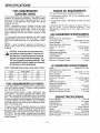
FUEL REQUIREMENTS
(GASOLINE UNITS)
OIL REQUIREMENTS
The recommended oils include the following:
These generators are equipped with gasoline fuel
systems as standard equipment. Specific installations may provide either a separate fuel tank for the
generator, or the generator may "share" the vehicle
engine's fuel tank.
NOTE: Installations using a "shared" fuel tank may
have a generator fuel pickup tube that is shorter than
the vehicle engine's pickup tube. Such an arrangement causes the generator engine to "run out of gas"
while adequate fuel for the vehicle remains in the
tank.
To reduce lead and carbon deposits use high quality
UNLEADED gasoline with the generator. Leaded
REGULAR grade gasoline is an acceptable substitute.
NOTE: Using "Unleaded" gasoline contributes to
longer engine valve life by reducing lead and carbon
deposits.
CAUTION: Generac does not recommend using
any gasoline containing alcohol, it must not contain more than 10 percent ethanol and it must be
removed from the generator during storage. Do
NOT use any gasoline containing methanol. If you
use gasoline with alcohol, inspect more frequently
for fuel leaks and other abnormalities.
FUEL REQUIREMENTS {LP UNITS)
These generators are equipped with a liquefied petroleum (LP) gas fuel system. LP gas is usually supplied
as a liquid in pressure tanks.
These generators require a "vapor withdrawal" type
fuel system. This type of gaseous fuel system uses
the vapors forming above the liquid fuel in the storage
tank. Air temperature around the storage tank must
be high enough to sustain adequate fuel vaporization.
In colder climates, you may need to use an independent heat source to be sure the fuel sufficiently vaporizes in the storage tank.
LP gas may consist of propane, butane or a mixture
of the two gases. Propane vaporizes at temperatures
as low as -20°F (-29°C), but butane returns to its liquid state when the temperature drops below about
32°F (0°C). For that reason, a higher ratio of propane
is desired in the gas mixture when temperatures drop
below freezing.
• During summer months: SAE 30. An acceptable substitute is SAE 1OW-30.
• During winter months: SAE 5W30. DO NOT USE SAE
10W-40.
Crankcase and oil filter capacity is about 950ml or
one (1) quart. Use no special additives. See
"Maintenance" section for oil level check and fill procedures.
GAS GENERATOR SPECIFICATIONS
Model .............................................. lmpact-36G plus
Rated Maximum Continuous
AC Power Output ...................... 3600 watts (3.6 kW)
Rated Voltage ....................................... 120 volts AC
Rated Maximum Continuous
Current at 120 volts.......................... 30 AC amperes
Phase ................................................... Single Phase
Rated AC Frequency
...... 60 Hz.
Recommended Battery
Cranking Current ....................................... 400 amps
Gross Weight. .................................................. 86 lbs
Maximum Cranking Current ........................ 250 Amps
Maximum Charging Current ............................ 2 Amps
LP GENERATOR SPECIFICATIONS
Model .......................................... lmpact-36LPG plus
Rated Maximum Continuous
3400 watts
kW)
AC Power Output
120 volts AC
Rated Voltage
Rated Maximum Continuous
28.3 AC amperes
Current at 120 volts
Single Phase
Phase
60Hz.
Rated AC Frequency
Recommended Battery
Cranking Current ....................................... 400 amps
Gross Weight
87 lbs
Maximum Cranking Current
... 250 Amps
Maximum Charging Current
....... 2 Amps
ENGINE SPECIFICATIONS
Type of Engine ............................................. GN-220
Cooling Method ......................................... Air-cooled
Displacement................................................... 220cc
Type of Governor ......... ... .. ............. .... ... .. .. Electronic
Air Cleaner ......................................... Paper element
Starter.......................................... 12 volt DC electric
Ignition System ......................................... Solid state
Recommended Spark Plugs ...... Champion RC12YC
Spark Plug Gap .......................... 0.030 inch (0.8mm)
-10-
MAINTENANCE
This section includes information about simple maintenance which includes the following tasks:
•
•
•
•
•
Checking engine oil level.
Changing engine oil.
Changing oil filter.
Air cleaner maintenance.
Cleaning the air intake screen.
Cleaning spark arrestor.
• Cleaning spark plug.
Replacing fuel filter.
Servicing inverter.
• Remove oil dipstick and fill crankcase with the recommended oil (See Page 10). The engine crankcase can
hold about 1 quart (950ml). DO NOT FILL ABOVE "FULL'
MARK.
• Install and tighten dipstick cap before operating engine.
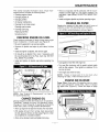
CHANGE OIL FILTER
Replace the engine oil filter after the first 8 hours of
operation, every 100 operating hours thereafter.
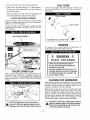
• Turn oil filter counterclockwise to remove (Figure 3).
Pimure B- Dil Elrain Plum and Engine Dil Pilfer
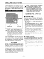
CHECKING ENGINE OIL LEVEL
Check engine crankcase oil level at least every eight
hours of operation, or before each use (Figure 2).
• Be sure the generator is as level as possible.
• Remove oil dipstick and wipe dry with clean, lint-free
cloth.
• Install and tighten oil dipstick, then remove again.
• Oil should be at dipstick FULL mark. If necessary, add
the recommended oil to the FULL mark only. DO NOT
FILL ABOVE "FULL' MARK.
• Install and tighten oil dipstick cap before operating the
engine.
OIL
DRAIN
PLUG
OIL
FILTER
• Coat gasket of new filter with engine oil.
• Turn new filter clockwise until its gasket contacts lightly
with the filter adapter. Then tighten an additional 3/4 to
one turn by hand.
• Run engine and check for leaks.
NOTE: Check oil level and fill to full mark after
checking for leaks. Filter will retain some oil.
ENGINE AIR CLEANER
Paper Filter: Once every 25 operating hours or once
each year (whichever comes first), clean or replace
the paper filter (Figure 4). Follow the steps on page
12.
~igure ~-
NOTE: See "Engine Oil Requirements" on Page 10
for recommended oils.
CHANGE ENGINE OIL
Change engine oil after the first 8 hours of operation.
Thereafter, change oil every 50 operating hours.
Change oil more frequently if operating consistently
under heavy load or at high ambient temperatures.
• Warm up engine for at least five minutes, then shut down.
• With engine still warm from running, clean area around
oil drain plug and remove oil drain plug (Figure 3). Drain
oil completely into a suitable container.
• When oil has drained, install and tighten drain plug.
-11-
Engine Air l:leamer Assembllll
PAPER
FILTER
• Remove air cleaner cover, then remove paper filter.
• Clean air filter by gently tapping it on a solid surface. If
the filter is too dirty, replace it with a new one, Dispose of
the old filter properly.
• Clean air cleaner cover then insert new paper filter into
cover and assemble to the base of the air cleaner.
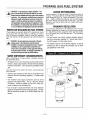
FUEL FILTER
Remove and replace fuel filter (Figure 7) every 100
hours of operation or once each year, whichever
occurs first.'
Figure 7; - Fuel Filfer
TO FUEL PUMP
CLEAN AIR INTAKE SCREEN
Clean all foreign material from the air intake screen
(Figure 5) at lease once every 100 hours of operation.
Clean more often if necessary.
Inspect the area around the generator exhaust muffler
periodically and remove all grass, leaves, dirt, etc.
from this area.
FUEL FILTER
Figure S- E:leam Air lnllaK:e Scmeem
AIR INTAKE SCREEN
CUSTOMER FUEL CONNECTION
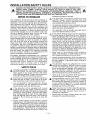
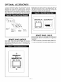
INVERTER
All repairs of the inverter MUST be handled by an
authorized service dealer (see Figure 8).
Figwre 8 - lmverter Warming Laiel
&
&
WARNING
HIGH VOLTAGE
ENGINE SPARK PLUG
Clean engine spark plug and set gap to 0.030 inch
(0.76mm) every 100 hours of operation (Figure 6).
Clean by scraping or wire brushing and washing with
commercial solvent. DO NOT BLAST CLEAN SPARK
PLUG.
UNIT TO BE SERVICED ONLY
BY AN
GENERAC
SERVICE DEALER.
AllOW 2 MINUTES FOR UNIT TO
POWER DOWN BEFORE OPENING
TO REDUCE RISK OF INJURY OR
ELECTROCUTION.
CLEANING THE GENERATOR
Keep your generator set as clean and dry as possible.
Dirt and moisture that are permitted to accumulate on
electrical windings have an adverse affect on the
insulation resistance of those windings.
Moisture that is allowed to remain in contact with windings will be retained in voids and cracks of the windings. Dirt makes the problem worse, since it tends to
hold the moisture into contact with the windings. Salt,
as from sea air, worsens the problem since it tends to
absorb moisture from the air. The combination of salt
and moisture makes a good electrical conductor.
Figure I - Setting Gal em Spark: Plug
SET PLUG GAP AT 0.030 inch
(0.76 mm)
CAUTION: Sparking can occur if wire terminal
does not fit firmly over spark plug terminal end. If
necessary, reform wire terminal to obtain a tight fit.
-12
CAUTION! Do NOT use a forceful spray of water to
clean the generator. Water will enter the generator
interior and cause problems, and may also contaminate the generator fuel system.
BATTERY
ADJUSTING THE CARBURETOR
All lead-acid storage batteries will discharge when not
in use. Inspect the generator battery as follows:
The carburetor of your generator is preset at the factory. The carburetor should not be tampered with, as
this wiii void the emission controi system warranty. if
your generator is used at altitudes in excess of 5,000
feet, consult your Generac Authorized Service Facility
regarding high altitude jetting changes.
• ONCE WEEKLY
Inspect battery posts and cables for tightness, corrosion. Clean and/or tighten as necessary.
Also check battery fluid level, and, if necessary, fill
with DISTILLED WATER ONLY. DO NOT USE TAP
WATER IN BATTERY.
• EVERY SIX MONTHS
Have the battery state of charge and condition
checked by an automotive service facility. This should
be done with an automotive type battery hydrometer.
DANGER: Storage batteries give off explosive
hydrogen gas. This can form an explosive mixture
around the battery for several hours after charging.
The slightest spark can ignite the gas and cause
an explosion. Such an explosion can shatter the
battery and cause blindness or other injury. Any
area that houses a storage battery must be properly ventilated. Do not allow smoking, open flame,
sparks or any spark producing tools or equipment
near the battery.
ADJUSTING VALVE CLEARANCE
After the first 50 hours of operation, you should adjust
the valve clearance in the engine.
When adjusting valve clearance, the engine should
be at room temperature and the piston should be at
Top Dead Center (TDC) of its compression stroke
(both valves closed). Correct clearance is 0.0010.003 inch (0.03-0.0?mm). Adjust valve clearance as
follows:
1. Loosen the rocker arm jam nut. Use an allen wrench to
turn the pivot ball stud while checking clearance between
the rocker arm and tne valve stem with a feeler gauge
(Figure 11 ).
Figure 11 -
~Cijustimg
lialve ~learamce
DANGER: Battery electrolyte fluid is an extremely
caustic sulfuric acid solution that can cause
severe burns. Do not permit fluid to contact eyes,
skin, clothing, painted surfaces, etc. Wear protective goggles, protective clothing and gloves when
handling a battery. If you spill the fluid, flush the
affected area immediately with clear water.
DANGER: Do not use any jumper cables or booster battery to
start the generator engine.
If any battery has discharged, remove it from the
vehicle for recharging.
SERVICE AND ADJUSTMENTS
• ENGINE SPEED
Engine speed is completely computer-controlled.
There is no adjustment for speed on the unit. The
computer adjusts the engine speed using an electronic governor throttle control. The computer monitors
the demand for power and adjusts the engine speed
accordingly. This allows the engine to produce only
the power required, resulting in fuel economy as well
as lowering the overall noise emitted.
NOTE: The computer will disable the electrical load
capabilities of the generator and enter a fault condition if you accelerate the throttle manually or any
other way.
-13
2. When valve clearance is correct, hold the pivot ball stud
with the allen wrench and tighten the rocker arm jam nut
with a crows foot. Tighten the jam nut to 65-85 inchpounds torque. After tightening the jam nut, recheck valve
clearance to make sure it did not change (Figure 12 on
page 13).
• Attach a tag to the engine indicating the viscosity and
classification of the oil in the crankcase.
e Remove spark plug and add about 1/2 ounce (15ml) of
clean, fresh engine oil into spark plug threaded opening.
Crank engine several times to distribute oil, then install
and tighten spark plug.
• Remove the battery and store in a cool, dry room on a
wooden board. Never store the battery on any concrete
or earthen floor.
• Clean and wipe the entire generator.
RETURN UNIT TO SERVICE
AFTER STORAGE
~
To return the unit to service after storage, proceed as
follows:
Tighten Jam Nut to
65-85inch-pounds
(7-10 N-m)
MAJOR SERVICE MANUAL
To obtain a service manual for your generator, order it
from your dealer/distributor or contact the factory. Be
sure to identify your unit's MODEL NUMBER and
SERIAL NUMBER.
EXERCISING THE GENERATOR
Generac recommends that you start and operate the
generator at least once every seven days. Let the unit
run for at least 30 minutes to "exercise" the engine.
• Check tag on engine for oil viscosity and classification.
Verify that the correct recommended oil is used in engine.
If necessary, drain and refill with proper oil.
• Check battery. Fill all cells to the proper level with distilled
water. DO NOT USE TAP WATER IN THE BATTERY.
Recharge battery to 100% state of charge, or, if defective,
replace the battery.
• Turn OFF all electrical loads, then start the engine.
• Let engine warm up.
• Apply electrical loads to at least 50% of the unit's rated
wattage capacity.
• When engine is thoroughly warmed up, shut it down.
THE GENERATOR IS NOW READY FOR SERVICE.
OUT OF SERVICE PROTECTION
If you cannot exercise the generator
days and it is to be out of service longer than
prepare the generator for storage as follows:
seven
days,
• Start the engine and let it warm up.
• While the engine is still warm from running, drain the oil
completely. Refill crankcase with recommended oil. See
"Specifications:'
SERVICE DEALER LOCATION
TO LOCATE THE NEAREST GENERAC SERVICING DEALER, PLEASE CALL OUR 800 NUMBER.
ONLY DEALER LOCATION INFORMATION CAN BE OBTAINED AT THIS NUMBER.
1-800-333-1322
-14-
INSTALLATION SAFETY RULES
IAI
IAI
I I DANGER: FOR FIRE SAFETY~ INSTALLATION OF A GENERATOR INTO A RECREATIONAL 1.1
VEHICLE MIJST COMPLY STRICTLY WITH ARTICLE 551, NFPA 70; ANSI Cf-1975; AND,
ANSI A119.2-1975/NFPA 501C "STANDARD FOR RECREATIONAL VEHICLES" (PART 3,
"INSTALLATION OF ELECTRICAL SYSTEMS"). IN ADDITION~ THE MANUFACTURER'S
INSTRUCTIONS AND RECOMMENDATIONS MUST BE COMPLIED WITH.
endangering people or animals.
NOTICE TO INSTALLER
The generator set produces dangerously high
The Installation Instructions have been published by
electncal voltage. Contact with bare wires, bare
Generac to aid in the installation of the products
terminals, etc., will result in extremely hazardous
described in this manual. Generac assumes that instaland possibly lethal electrical shock.
lation personnel are familiar with the procedures for
• All applicable electrical codes, standards and reginstalling such products, or similar products that
ulations must be strictly complied with in the instalGenerac manufactures. Generac also assumes that
lation and use of this equipment.
personnel have been trained in the recommended
• The generator must be properly grounded (bondmstallation procedures for these products and that
ed) to the vehicle chassis or frame.
such training includes (a) use of common hand tools,
(b) use of special Generac tools, and (c) use of any
A If the vehicle electrical circuits can be powered by
tools and/or equipment from other suppliers.
l l l any other source of electricity (such as a "dockside"
power receptacle), there must be no possibility of
We could not possibly know of and advise the recreconnecting the different power sources to the vehiational vehicle trade of all conceivable methods, procecle circuits at the same trme. The "dockside" (utility)
dures or techniques by which to perform an installapower source must be positively isolated from the
tion. We could not know of the possible hazards that
vehicle circuits whenever the generator is operatmight result from each installation method, procedure
ing. Failure to isolate the vehicle circuits from the
or technique. We have not undertaken any such wide
dockside power supply when the generator is runevaluation. Therefore, people who use a method, proning may result in damage to the generator or sericedure or technique that Generac does not specifically
ous injury or death to dockside (ut11ity) power workrecommend must first completely satisfy themselves
ers due to backfeed of electrical energy.
that their safety, the safety of the vehicle's occupants
and the product's safety is not endangered by the
• Never work on the equipment while standing in
method, procedure or technique selected.
water, while barefoot, or while hands or feet are
wet. Dangerous electrical shock will result.
Information, illustrations, specifications, etc., contained
in this Installation Manual are based on the latest infor• Jewelry conducts electricity, which can cause danmation available at the time of publication. Every effort
gerous electrical shock. Remove all jewelry (such
has been expended to be sure that such data is both
as rings, watches, or bracelets) before working on
accurate and current. However, the manufacturer
this equipment.
reserves the right to change, alter or otherwise
A
The
generator requires an adequate flow of air for
improve this product at any time without prior notice.
.A. cooling and ventilation. Without sufficient cooling
air flow, the engine-generator quickly overheats,
SAFETY RULES
which causes serious damage to the generator, a
fire or an explosion. Generator air inlet and outlet
Gasoline is extremely FLAMMABLE and its vapors
openings must be provided in strict compliance
are EXPLOSIVE. Do not permit smoking, open
with the manufacturer's recommendations.
flame, sparks or any source of heat in the vicmity
while handling gasoline. Comply with all laws gov• Never work on this equipment while physically or
erning the storage and handling of gasoline.
mentally fatigued. Stay alert at all times.
A Fuel lines must be properly installed, properly fasStorage batteries give off EXPLOSIVE hydrogen
an. tened and free of leaks. There must be no possigas while charging. The battery used for cranking
bility of gasoline vapors entering vehicle interior.
and starting this generator should be installed in
its own vented compartment. Provide adequate
• You are required to install an approved, flexible,
ventilation for the battery, to prevent explosive
non-conductive fuel line between the generator
hydrogen gas from accumulating.
fuel connection point and rigid fuel lines.
A Never insert any tool or other object through openlA If the generator can be equipped with a liquid
.&. ings in the generator interior, even if the unit is not
.8. propane (LP) gas fuel system, install the unit so it
running. You might seriously injure yourself or
complies with all codes, standards and regulations
damage the equipment.
pertaining to such systems. LP gas is highly explosive. The gas tends to settle in low areas where
• Staying alert and using "common sense" are major
even the slightest spark can ignite it and cause an
measures for preventing accidents.
explosion. Do not allow gas vapors to enter the
vehicle.
• Engine exhaust gases contain DEADLY carbon
monoxide gas. This dangerous gas, if breathed in
sufficient concentrations, can cause unconsciousness or even death. Install the exhaust system in
strict compliance with applicable codes, standards
and regulations. There must be no possibility for
exhaust gases entering the vehicle interior and
&
JJe.
-15-
GENERAL INSTALLATION INFORMATION
3.ANSI Ci-1975 and ANSI119.2-1975, available from the
American National Standards Institute, 1430 Broadway,
New York, NY 10018.
PURPOSE AND SCOPE OF MANUAL
These Installation Instructions have been prepared
especially for the purpose of familiarizing installers and
owners of the applicable equipment with the product's
installation requirements. Give serious consideration to
all information and instructions in the Manual, both for
safety and for continued reliable operation of the
equipment.
Because of the different recreational vehicle models
and the variations between the models, it would be
extremely difficult, if not impractical, to provide detailed
instructions on every installation possibility. For that
reason, instructions and illustrations in this manual are
general in nature. Illustrations are not intended to
serve as detailed installation blueprints.
The installation should comply strictly with all applicable codes, standards and regulations pertaining to the
installation and use of this product. If any portion of
this manual appears to be in conflict with such codes,
standards or regulations, the applicable codes, standards or regulations must take precedence over the
manual.
4. ANSI A119.2/NFPA 501 C, available from the Recreational
Vehicle Association, 1896 Preston White Drive, Reston, VA
22090.
5. California Administrative Code, Title 25, available from the
State of California, Documents Section, P.O. Box 1015,
North Highlands, CA 95660.
6. CSA Electrical Bulletin 946, available from the Canadian
Standards Association, Housing and Constructions
Materials Section, 178 Rexdale Boulevard, Rexdale,
Ontario, Canada, M9W 1R3.
EQUIPMENT DESCRIPTION
Instructions and information in this section pertain to
Generac Impact air-cooled generators- more specifically, the installation of lmpact-34 plus and lmpact-36
plus recreational vehicle generators. These generators
are designed specifically for installing in recreational
vehicles.
SAFETY
Before handling, installing, operating or servicing this
equipment, be sure to read carefully the "Notice to
Installer" and "Safety Rules" at front of this manual.
Comply with all SAFETY RULES to prevent death, personal injury or damage to equipment and/or property.
Stress safety to all installers, operators and service
technicians who work on this equipment.
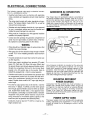
ENGINE GENERATOR
OPERATING SPEED
The generators are driven by gasoline-powered, single-cylinder engines. The engines drive revolving fields
(rotors), high frequency, permanent magnet alternators. The generators supply 120 volts AC at 60 Hertz
with DC inverter. The generators revolving fields are
driven at a variable speed depending on the demand
for power. Computers monitor that demand and adjust
the engine speed to provide adequate power to the
connected loads.
STANDARDS BOOKLETS
Installation, use and servicing of this equipment should
comply strictly with published standards, as well as the
manufacturer's recommendations. The following standards booklets (latest revision) are available from the
sources indicated:
i. NFPA Standard 501
"Standard for Recreational
Vehicles", available from the National Fire Protection
Association, Batterymarch Park, Quincy, MA 02269.
2. NFPA 70, "NFPA Handbook of the National Electric Code",
obtained from same address as Item 1.
16
LOCATION AND SUPPORT
GENERATOR LOCATION
The most desirable location for the generator set is
between the vehicle's main frame members However,
this is seldom possible. Most units must be installed on
the side of the vehicle and are difficult to reinforce.
Many recreational vehicles have been factory
equipped with an area for the generator set. Some
vehicles may even have a generator compartment,
provided by the vehicle manufacturer.
Plan the generator location based on the following:
• The generator set must be installed on a framework that is
part of the recreational vehicle, as outlined in the paragraph entitled "Generator Support."
• The location must provide an access opening that is large
enough to permit generator removal (unless the generator is
to be removed from underneath the supporting framework.
• The location must provide easy access to frequently serviced components, such as filters, oil drains, spark plugs
and other common maintenance parts.
• The location must provide sufficient room to allow minimum clearance of at least 1 inch between all sides and 11/2 inches on top of the generator. If sound insulation is to
be used on compartment walls and ceiling, the minimum
recommended applies to the space between the generator
and such insulation.
• The location must provide adequate cooling and ventilating
air flow for the generator without a great deal of work and
expense.
SUPPORT
TUBING
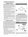
SUSPENDED MOUNTING
If you are going to suspend the generator below the
horizontal support tubing, the suspension method you
use with the vehicle frame members must have the following: (a) be able to support the weight of the generator; and (b) provide sufficient restraint for the generator. One typical suspended mounting system is shown
in Figure 15. The location of a suspended mounting
system must be carefully planned, keeping the following general rules in mind:
• Protect the generator against road splash and debris.
Baffles or splash guards may be required to protect certain
areas of the generator. To make sure the generator is adequately protected, road test the installation through mud,
water and slush.
GENERATOR SUPPORT
The generator must be securely attached to a metal
framework that has been made part of the vehicle
frame structure by bolting or welding. The metal framework on which the generator will rest and which will
restrain the generator set should consist of at least two
horizontal beams. These beams should consist of (a)
1-1/2 inch square, 11 gauge steel tubing OR (b) 1-1/2
inch, 11 gauge angle iron. A typical supporting frame
with horizontal support tubing, is shown in Figure 14.
The generator can be installed so that it sits on top of
the horizontal support tubing, if the vehicle design permits. Another method is to suspend the generator
below the horizontal support tubing by means of suitable, structurally sound metal framework. The following
general rules apply:
GENERATOR MOUNTING
HOLES FOR J/8"·16
BOLTS (BOTH SIDES)
y
• Vehicle construction MUST be capable of supporting the
weight of the generator.
• Whether the generator is mounted above the horizontal
support tubing or suspended below the tubing, the supporting frame used must be structurally sound.
• If the generator cannot be bolted directly to the supporting
frame or support tubing, consider using additional tubing,
angle brackets or other supports to give the supporting
frame sufficient strength.
• The installer must make certain that selected location will
permit adequate cooling and ventilating air flow to be supplied.
17
figure 1 o -
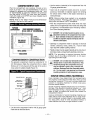
GENERATOR RESTRAINT
Use four 3/8"-16 hardened steel bolts (Gmde 5) to fasten the generator to the supporting frame or the support tubing. These bolts must pass through (a) the
generator mounting base, (b) the compartment floor, if
a compartment is used, and (c) the supporting framework (Figure 16). Aii bolts must be iong enough so that
when tight, at least 3 threads are visible past the
retaining lock nuts. Refer to "COMPARTMENT" section
for location of generator mounting holes.
T~pical
f3enerator
METAL UNED
~estraint
1/2 INCH THICK
BASE
PLYWOOD
-~
METAL UNED
BOTTOM
VEHICLE
CHASSIS
GENERATOR COMPARTMENTS
COMPARTMENTS
The generator set may or may not be installed inside a
compartment that is constructed specifically for housing a generator. This section applies to generator compartments when they are installed. The following general rules apply to compartments:
• The generator compartment should be either constructed of, or lined with, 26 gauge galvanized
steel.
IMPORTANT: ALUMINUM IS NOT AN ACCEPTABLE
ALTERNATIVE TO GALVANIZED STEEL, DUE TO
ALUMINUM'S LOW MELTING POINT.
• If the compartment is lined with galvanized steel, it
may be constructed of any material. Generac recommends that the compartment be constructed of
1/2-inch thick plywood, with the floor made of a
double thickness of plywood for added strength.
• All seams, splices and joints of the compartment
walls (unless vapor tight
design) should be
caulked.
IMPORTANT: CAULKING MUST BE DONE SO THAT
THE CAULKING MATERIAL WILL STAY IN PLACE
PERMANENTLY. PRESSING SUCH MATERIALS AS
PUTTY TAPE ONTO JOINTS AND SEAMS WILL NOT
MEET THAT REQUIREMENT. A HIGH QUALITY SILlCONE RUBBER SEALANT IS RECOMMENDED.
• Holes and openings through the compartment
walls for passage of electrical conduit, conductors,
etc, into vehicle living area must be sealed vaportight with silicone rubber base sealant.
• If you use flexible metal conduit, seal the conduit
at the end where it terminates inside the junction
box. Flexible metal conduit is NOT vapor tight
along its entire length.
Seams and joints of the galvanized steel (whether
used as a liner or the compartment itself) must be
lapped and mechanically secured. Such seams
may be manufactured, welded, bolted, riveted, or
screwed. Manufactured lock seams are shown in
Figure 17.
ACME LOCK
FOLD LOCKED STANDING
DOUBLE LOCK
OFFSET
DOUBLE SEAM
GORDON SEAM
LOCK SEAM
STANDARD LAP JOINT
-18-
COMPARTMENT SIZE
Plan the compartment size carefully. Provide a minimum of at least 1 inch (2'' recommended) of clearance
between the generator and compartment walls and 1 inch
(2'' recommended) of clearance between the generator
and the ceiling AFTER you have lined the compartment with metal, and AFTER you have installed sound
insulation (Figure 18).
NOTE: Refer to the "Major Features and Dimensions"
drawing in the back of this manual.
PLYWOOD
COMPARTMENT
1 INCH MINIMUM CLEARANCE
ON All SIDES (2 11 RECOMMENDED)
11NCH
MINIMUM
CLEARANCE
ABOVE
GENERATOR
(2" RECOMMENDED)
TOP VIEW OF
GENERATOR
METAL LINING----'
~----INSULATION
• Line the exterior (underside) of the compartment floor with
26 gauge galvanized steel.
Vapor seal all compartment seams and joints, to prevent
poisonous, flammable or explosive vapors from entering
the vehicle interior. Refer to the sealant information as
noted previously.
NOTE: Silicone rubber base sealant is an acceptable
caulking material. Pressing putty tape onto compartment joints and seams is NOT acceptable.
• After the compartment has been metal lined and vapor
sealed, line the compartment interior walls and ceiling with
an approved, non-flammable sound insulating material.
See "Sound Insulating Materials."
DANGER: Do not install sound insulation or any
absorbent material on the compartment floor interior. Such materials will become soaked with combustible or explosive vapors and liquids and will
become a fire hazard.
• Openings in compartment walls for passage of electrical
conduit, conductors, hoses, cables, etc., must be made
vapor tight with suitable caulking material.
• Flexible conduit must be sealed internally at the end where it
terminates inside a compartment's electrical junction box.
NOTE: The preceding is required because flexible
conduit, due to its unique construction, is not vaportight along its entire length.
COMPARTMENT CONSTRUCTION
DANGER: Do not install any flammable material
directly above or around the compartment. Heat,
transferred through the compartment structure,
may sufficient to ignite, char or discolor seat
cushions, fiberboard and other flammable materiYou may need to use approved non-flammable
insulating materials in high temperature areas.
The generator compartment should be constructed of 1/2
inch thick plywood. Make the compartment floor a double
thickness of 1/2 inch plywood
the grain of the wood at
cross section for added strength (Figure 1
CROSS..SECTION lllEW
SOUND INSULATING MATERIALS
METAL LINING
PLYWOOD
Once installers have determined that compartments
are properly constructed and metal lined, they can add
acoustical material. This may include additional
sealant or insulating material, to reflect noise away
from the vehicle interior.
Sound insulating materials should be of a non-flammable type. One excellent insulating material is a 1 inch
thick fiberglass having a 2-pound density. When fiberglass is used, its coated side should face toward the
compartment interior.
Using a combination of sound insulating materials can
often reduce noise more effectively than a single material. For example, a sheet of lead or visco-elastic material, along with a layer of other acoustical material, is
more effective than when a single material is used.
• Line the entire compartment interior with 26 gauge galvanized steel as described above.
19-
~.
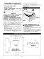
COMPARTMENT FLOOR CUTOUTS
You must provide openings in the generator compartment for the following items (Figure 20):
• Engine exhaust and cooling air outlets
• Generator cooling air inlet
• Four holes for passage of generator mounting bo!ts. See
"Generator Restrainf on Page 19.
• Vapor seal all compartment seams and joints.
• Over the galvanized steel lining, install a selected combination of acoustical materials as mentioned in "Sound
Insulating Materials."
Q
DANGER: Fuel lines and exhaust piping must not
~ penetrate into vehicle living area.
ACOUSTICS
If excessive noise levels should become a problem,
the installer may wish to consider the following:
• Using special sound insulating materials.
• Construction of a special noise abatement compartment.
IMPORTANT: ANY METHOD USED TO REDUCE
NOISE MUST NOT ADVERSELY AFFECT THE
FLOW OF COOLING AND VENTILATING AIR INTO
OR OUT OF THE COMPARTMENT.
In addition to the effective use of sound insulating
materials, construction of a special noise abatement
compartment might be considered to reduce noise levels. Such a compartment might be constructed as follows (Figure 21 ):
• Use 5/8-inch thick or 3/4-inch thick plywood in the compartment.
• Construct the compartment floor of a double thickness of
5/8-inch or 3/4-inch plywood.
• Line the compartment interior walls and floor, as well as
the underside of the floor, with 26-gauge galvanized steel.
FIIIEIIGI.ASS
INSUI.ATIDM
DANGER: Do not install any insulation or other
absorbent materials on the interior or underside of
the compartment floor.
• Seal all compartment door edges to prevent noise leakage
around the door perimeter.
• Line the compartment door interior (except for air openings) with suitable, fire proof sound insulation (such as
1-1nch thick fiberglass with a 2-pound density).
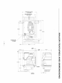
1 - - - - - - - - 4 6 0 , . . . , [ !B. l l ' l - - - - - - - - 1
I-------400....C!5.75'J--------l
\
!
\
\
09ovo [0.J5'l
i
i
\
i
\ i
\ i
\i
\i
\i
v
4
HOLCS~
FULL SIZE COMPARTMENT TEMPLATE
CDRA\IING NUMBER A6203>
~
FOR A FULL SIZE TEMPLATE,
CONTACT GENERAC RV SERVICE
DEPARTMENT AT:
i
~
"'
~
A
i\
!\
i \ ~
i \
i \
i \
i~ '
i
l:
""' ,L
EXHAUST
/
ND AIR
1-800-526-2871
L T
//
DRAWING PART NO. A6203
i
IG.ES - 4 •EOUIR( D
-20
COOLING AND VENTILATING AIR
It is absolutely essential that an adequate flow of air for
cooling, ventilating and engine combustion be supplied
to the generator set. Without sufficient air flow, the
engine-generator quickly overheats. Such overheating
can cause serious operating difficulties and may also
cause fire and personal injury. The installer must make
sure that sufficient air is available to the generator for
cooling, ventilating and combustion. The installer must
also provide for a path for exhausting the cooling air to
the exterior of a compartment, if so equipped.
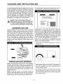
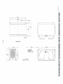
For conventional compartment mounted units, the air
inlet is generally provided in the compartment door.
-~-m
10 SQUARE INCHES
(OPTIONAL OPENINGS)
DANGER: Never use discharged cooling air for
heating or permit such air to enter the vehicle interior. This air contains deadly carbon monoxide gas
and other poisonous, flammable or explosive gases.
40 SQUARE--::::.:-._
INCHES
(MINIMUM
OPENING)
cw
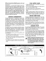
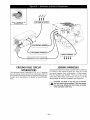
GENERATOR AIR FLOW
Engine operation drives cooling fans for the 2-stage
cooling air system. A pressure fan draws cooling air
into the top of generator and into the side of the control
panel (Figure 22). This air flow cools the engine-generator and electronic components. The second part of
cooling system, a suction fan, draws air that is heated
from a hot engine into a collector pan at the base of
the unit. This heated air (although cooler than exhaust
muffler) is directed across the muffler to cool it. The
heated air flow is then deflected out the bottom toward
the ground.
IMPORTANT: IF YOU PLAN TO INSTALL THE GENERATOR IN A COMPARTMENT, BE SURE TO
LEAVE AT LEAST ONE INCH (2" RECOMMENDED)
OF CLEARANCE BETWEEN THE GENERATOR AND
COMPARTMENT WALLS AND CEILING. INCLUDE
26 GAUGE GALVANIZED STEEL LINING AND
SOUND INSULATION WHEN YOU MEASURE FOR
THIS 1 INCH (2'' RECOMMENDED) CLEARANCE.
When the unit is installed on a suspended mounting
system, one of several different methods of supplying
air flow may be used as follows:
• Provide a door in the vehicle skirt having an air inlet opening (Figure 24).
qr.
COOLING AIR INLET OPENINGS
Ideally, you should provide three air inlet openings,
whether the generator is housed in a conventional
compartment or not. Two of the openings should be 10
square inches and located as shown in Figure 23. The
third opening should provide for a minimum of 40
square inches unrestricted and be located lower on the
compartment door.
NOTE: Screening, louvers, or expanded metal that
cover air openings restrict air flow that you must compensate for by making the actual air opening proportionately larger. See "Compensating for Restrictions."
• Using ductwork (Figure 25 on Page 23). The installer must
be sure air is available to the top of the generator since air
inlets are located at the top.
• By providing an opening in the vehicle skirt and space
above the generator for cooling air flow (Figure 26 on Page
23). Recommended clearance above the top of the generator is at least 2 inches.
-21-
Some materials may offer only a 60 percent "free air
inlet area." Other more efficient materials may provide
uo to a 90 percent free air inlet area. The oercentaae
of free air fnlet opening is usually availabie from the
material supplier or manufacturer.
TO DETERMINE THE ACTUAL AIR INLET OPENING
SIZE REQUIRED, DIVIDE 40 SQUARE INCHES BY
THE PERCENTAGE OF FREE AIR INLET AREA
FOR THE MATERIAL YOU WILL USE.
For example: If you plan to use screening with an 80%
free air inlet area, divide 40 by 0.8, which results in 50
square inches. Minimum actual size of air inlet opening
in this case is 50 square inches. An opening that measures 4 inches wide by 12-1/2 inches long provides the
required air flow (4 x 12.5 = 50 square inches).
AIIITI..£PWH
--,
!iEIIIEMTDR
I
'
Wfll
I
,;
''
INVERTER LOCATION
The inverter should be located in a dry, well ventilated
area in order for the inverter to work effectively.
Approximately eight inches of space should be allowed
at each end of the inverter for adequate ventilation.
The sensing harnesses supplied with the inverter have
a maximum length of 12 feet. If the cables are longer
than needed, coil the excess near the inverter unit. If a
greater length is needed, contact Generac. DO NOT
ATTEMPT TO SHORTEN OR LENGTHEN THE SUPPLIED SENSING HARNESSES. The DC power wires
may be cut to the required length. Allow enough
length to make connection. Coil excess inside J-Box.
Pimure 26- Air lnletr in ~eli'licle Sl<irt
RECIIIIIIMENIIED
CLEARANCE
ISZ"
j_ c===============:
n
Mll'llll\4111111
CLEARANCE
I"
TESTING THE INSTALLATION
Generac recommends testing the installation to be
sure adequate cooling air flow is available to the unit
before placing the unit into service. If the unit shows
signs of overheating, you will need to enlarge the air
openings. Never place a unit into service until
absolutely certain that cooling and ventilation is adequate.
IMPORTANT: YOU MUST TEST THE INSTALLATION
ESPECIALLY IF YOU BRING IN AIR FROM BELOW
THE GENERATOR SET.
COMPENSATING FOR RESTRICTIONS
Such materials as
louvers, or expanded
metal can restrict the free flow of air. Compensate for
this restriction by making the actual air opening proportionately larger.
22
GASOLINE FUEL SYSTEM
CAUTION: Do NOT tee the generator fuel supply line
into the vehicle engine fuel supply line. If this is
done, the generator will be starved of fuel when
both engines are operating at the same time. Also,
while the vehicle engine is not running, generator
operation may drain the vehicle engine supply line,
making it difficult to start the vehicle engine.
Installing a gasoline fuel system (Figure 27) for recreational vehicle generator sets must comply with applicable codes, standards and regulations. The entire fuel
system must be completely free of leaks. There must
be no possibility of gasoline vapors entering the vehicle interior.
figure 2'"'1 - f:'iernera:t:cu fuel
S~s:t:em
GENERATOR FUEL SUPPLY LINE
• RIGID FUEL LINES
Those lines used to supply fuel from a tank to the generator must comply with applicable codes, standards
and regulations. The following generator rules apply to
rigid fuel lines:
ELINLET
CARBURETOR
• Rigid lines should be of annealed, seamless, drawn aluminum or steel.
• Lines and fittings must comply with SAE J512F, "Standard
Automotive Fittings", or with ANSI 8126.26 (latest edition).
• Route the fuel line so that at least 2 inches of clearance is
maintained between the line and any exhaust system
parts.
• Do not attach electrical wiring to fuel lines. Route the
wiring so it cannot come into contact with any fuel line.
• Route fuel lines so if they leak, fuel does not drip onto any
electrical or exhaust system parts.
non~ferrous metal straps without sharp edges to
secure fuel lines.
FUEL PUMP
DANGER: Gasoline is highly flammable and its
vapors are explosive. Comply with all codes, stan·
dards and regulations pertaining to gasoline fuel
systems used in mobile generators. Dl't'l,nor'h'
and maintain the fuel
and keep it
free of leaks. Gasoline vapors must not enter
vehicle interior.
Factory installed generator fuel system components
include (a) fuel filter, (b) 12-volt DC electric pump, (c)
engine carburetor, and (d) interconnecting lines and fittings. Connect a fuel supply line to the fuel filter inlet.
Use a flexible length of approved fuel hose between
the fuel filter inlet connection and rigid fuel lines.
• FLEXIBLE FUEL LINE
Use an approved flexible length of fuel hose between
the generator fuel inlet connection and rigid fuel lines.
This prevents breaking of the line caused by vibration,
shifting, settling or movement. The following rules
apply:
• The flexible hose must comply with SAE J30B, "Standard
for Fuel and Oil Hose". It must be approved for use with
gasoline.
• The hose should be at least 6 inches longer than is need~
ed to prevent the hose from rupturing if the generator shifts
or settles.
FUEL TANK
Either the generator must share the vehicle engine's
fuel tank, or you must install a separate fuel tank for
the generator set. All fuel tanks installed on the vehicle
must be constructed, installed, restrained so it complies with applicable codes, standards and regulations.
If the generator is to share the vehicle engine's tank,
separate fuel pickup tubes are required for the engine
and the generator. Generac recommends that you
make the fuel pickup tube 2 to 3 inches shorter than
the vehicle engine's pickup tube. This prevents the
generator from depleting the entire fuel supply during
prolonged generator operating periods.
23
PROPANE GAS FUEL SYSTEM
DANGER: LP (propane) gas is highly explosive. The
gas is heavier than air and tends to settle in low areas,
where even the slightest spark can ignite it and cause an
explosion. Only competent, qualified persons should be
allowed to install, test, adjust or service an LP gas fuel
system. Install the optional fuel system in compliance
with applicable codes, standards and regulations. After
the installation, do nothing that might render the system
in non-compliance with applicable codes and standards.
PARTS NOT INCLUDED IN FUEL SYSTEM
The propane fuel system does NOT include such items
as (a) gas tank, (b) gas piping, (c) fittings, (d) valves,
and (e) primary regulator, used to store the gaseous
fuel and deliver it to the gaseous fuel solenoid (Figure
28).
DANGER: Use only approved components in the gas
supply system. All components must be properly
installed in accordance with applicable codes. Improper
installation or use of unauthorized components may
result in fire or an explosion. Follow approved methods
to test the system for leaks. No leakage is permitted. Do
not allow fuel vapors to enter the vehicle interior.
VAPOR WITHDRAWAL
Liquid propane (LP) gas is stored in pressure tanks as
a liquid. The gas systems used with these generators
were designed only for "vapor withdrawal" type systems. Vapor withdrawal systems use the gas vapors
that form above the liquid fuel in the tank, Do NOT
attempt to use the kit along with any "liquid withdrawal"
type system.
PRIMARY REGULATOR
Gas pressure delivered to the solenoid valve must be
properly regulated by means of a primary gas regulator. Mount the primary regulator at the gas tank outlet
or in the supply line from the gas tank, The following
rules apply:
• For best results, the primary regulator supplies gaseous
fuel to the secondary regulator at 11 inches water column.
Do NOT exceed 14 inches water column.
• The installer must be sure the primary regulator is rated at
sufficient gas flow to operate the generator plus all other
gas appliances in the circuit.
SOME IMPORTANT CONSIDERATIONS
When installing an LP gas system, consider seriously
the following items:
All fittings, lines, hoses and clamps must be tight and free
of leaks. Apply a pipe sealant to threads when assembling
threaded connections. This reduces the possibility of leakusing approved
Test the entire fuel system for
test methods.
• Optimum gas pressure at the inlet to the gaseous fuel
solenoid valve and secondary regulator is 11 inches water
column.
• The installer's fuel supply connection point is at the
gaseous fuel solenoid valve. This is a 3/4 inch (female)
connection. Provide a suitable 3/4 inch NPT (male) connector to attach to the fuel supply line.
• Use a length of approved flexible fuel hose between
gaseous fuel solenoid valve and rigid gas piping. The flexible line should be at least six (6) inches longer than necessary.
-24
FUEL
UICIOFF
SIJL.ENOIII
NOTE: Recommended MINIMUM gas flow rate for all
air-cooled lmpact-34 plus series generators is 67 cubic
feet per hour.
IMPORTANT: IF AN EXISTING PRIMARY GAS REGULATOR DOES NOT HAVE A SUFFICIENT FLOW
CAPACITY FOR THE GENERATOR AND OTHER
GAS APPLIANCES IN THE CIRCUIT, (a) INSTALL A
PRIMARY REGULATOR WITH ADEQUATE FLO\'V
RATE, OR (b) INSTALL A SEPARATE REGULATOR
RATED AT LEAST 67 CUBIC FEET PER HOUR. THE
INLET SIDE OF ANY PRIMARY REGULATOR THAT
SUPPLIES THE GENERATOR MUST CONNECT
DIRECTLY TO GAS TANK PRESSURE. DO NOT
TEE THE GENERATOR LINE INTO A GAS CIRCUIT
FEEDING OTHER APPLIANCES.
~~
•
•
•
•
FUEL SUPPLY LINES
Propane gas lines must be accessible, but protected
against possible damage.
Do NOT connect electrical wiring to any propane gas fuel
line or run wiring alongside the lines.
Route gas lines away from hot engine exhausts.
Retain gas lines with metal clamps that do not have sharp
edges.
Install an approved length of flexible hose between the
gaseous fuel solenoid valve and rigid fuel supply lines.
The flexible line must be non-metallic, non-organic and
non-conductive. It must be approved for use with LP gas.
EXCESS FLOW VALVE
GASEOUS CARBURETION
Propane gas tanks should have an excess flow valve,
according to NFPA 501 C, Paragraph 3-4.4. This valve
and the gas lines must be carefully sized so the valve
will close when a fuel line is severed or broken.
Consult the Naturai-LP Gas Association for information
and limitations of excess flow valves.
Manual shutoff valves on the supply tank and elsewhere in the system must be fully open when operating the generator. The excess flow valve functions
properly only if all valves are fully open.
LP gas vapors should be supplied to the generator
regulator inlet at about 11 inches water column (positive pressure). The engine piston draws air in during
the intake stroke (Figure 29). This air passes through
a carburetor venturi which creates a low pressure that
is proportional to the quantity of air being pumped.
The low pressure from the carburetor venturi acts on
the regulator diaphragm, to pull the diaphragm toward
the source of low pressure. A lever attached to the
diaphragm opens a valve to permit gas flow through
the carburetor.
The greater the air flow through the carburetor venturi,
the lower the pressure at the venturi throat, the greater
the diaphragm movement and the greater the movement of the regulator valve. The more the regulator
valve opens, the greater the gas flow that is proportional to air flow through the carburetor.
The following facts about the secondary regulator must
be emphasized:
LEAKAGE TESTS
Do not place the generator into service until you have
properly tested the gas system for leaks. To test the
system, you need a separate source of 12 volts DC to
open the gaseous fuel solenoid valve.
The leak test must comply fully with NFPA, Paragraph
318. All connections, hoses, valves, regulators, fitting,
and other fuel system parts must be tested under gas
or air pressure of not less than 90 psi (620kPa). while
using soap and water or equivalent solution to check
for leaks. Other approved methods of testing for leaks
may be used, if appropriate DO NOT USE ANY
FLAME TO TEST FOR LEAKS.
• The regulator must
sensitive to venturi throat pressure
changes throughout the operating range.
• The regulator must be properly adjusted so it will stop the
flow of gas when the engine is not running (no air flow
through the carburetor).
~~ The slightest air flow (and vacuum) in the venturi throat
should move the regulator valve off its seat and permit gas
to flow.
DANGER: Gaseous fuel lines between the tank and
the secondary regulator are under a positive pressure (about 11 inches water column). Gas pressure
at the outlet side of the secondary regulator, however, is a negative pressure (about 1-inch water column) and can draw flame inside a line or fitting and
cause an explosion.
~AIRFLOW
D
GAS AT ZERO PRESSURE
LOW PRESSURE AREA
25-
EXHAUST SYSTEM
The generator exhaust
properly installed. Only
exhaust system parts
installed exhaust system
completely safe.
system must be safely and
approved mufflers and other
must be used. A properly
must be vapor tight, quiet and
CAUTION: Never tee the generator engine exhaust
pipe into the vehicle engine exhaust piping. This
causes excessive back pressure on the generator
engine. Also, water from one engine can damage
the other engine.
DANGER: The generator engine gives off deadly
carbon monoxide gas through its exhaust system.
This dangerous gas, if breathed in sufficient concentrations, can cause unconsciousness or even
death. Symptoms of carbon monoxide poisoning
are (a) inability to think coherently, (b) vomiting, (c)
twitching muscles, (d) throbbing in temples, (e)
dizziness, (f) headache, (g) weakness and sleepi·
ness. If any of these symptoms ar experienced,
move into fresh air immediately. If symptoms persist, get medical attention. Do not operate the generator until its exhaust system has been inspected
and repaired.
MUFFLERS AND SPARK ARRESTORS
Exhaust mufflers and spark arrestors that Generac
supplies meet code and standard requirements, and
are approved by the U.S. Forest Service. Use only
mufflers and parts approved by Generac. Any
person(s) installing an unapproved muffler, or an unapproved exhaust system part, or modifying an exhaust
system in any way that might cause a hazard, is liable
for any damage, injury or warranty expense that might
be caused by such unapproved installation or modification.
Failure to provide and maintain a spark arrestor may
be in violation of the law. If this generator is used on
any forest covered, brush covered, or grass covered
unimproved land, you must provide a spark arrestor.
The vehicle owner or operator must maintain this
device in good condition. In the State of California, the
preceding is required by law (Section 4442 of the
California Public Resources Code). Other states may
have similar laws. Federal laws apply on federal lands.
EXHAUST SYSTEM SAFETY
• Maintain a clearance of at least 3 inches (76mm) between
exhaust system parts and any combustible material (such
as wood, felt, cotton, organic fibers Oi other like material).
If you cannot maintain the 3-inch clearance, locate, insulate or shield the exhaust part(s) so that the temperature of
any combustible material is not raised more than 11 rF
(65°C) above the ambient air temperature.
• Extend the exhaust system at least one inch (25mm) past
the outer edge of the vehicle. Do not terminate the exhaust
system under the vehicle.
• Terminate the exhaust tailpipe such that exhaust gases will
not be drawn back into the generator compartment and
recirculated.
• If there is any possibility of the tailpipe or muffler being
damaged, protect these damage prone areas by means of
a protective device (such as a "skid bar'').
• Install the generator exhaust system according to safe
automotive practices.
• Use enough exhaust system hangers to prevent any part
of the system from being dislocated.
• Use exhaust system parts recommended by Generac.
Using unapproved exhaust mufflers and exhaust system
parts is the responsibility of the person(s) installing such
unauthorized parts.
• Do not terminate the exhaust system under any opening,
window or vent which can be opened or is not permanently
sealed from the vehicle interior.
Exhaust piping must be large enough to prevent excessive
back pressure on the generator engine.
• Never tee the generator engine exhaust pipe into the vehicle engine exhaust piping. This causes excessive back
pressure on the generator engine. Also, water from one
engine can damage the other engine.
• Plan exhaust system installation carefully. Comply with all
applicable codes, standards and regulations.
TYPE OF EXHAUST SYSTEM
The lmpact-36 plus and lmpact-34 plus generators have
a configuration for a bottom out exhaust system and is
equipped with such an exhaust muffler (Figure 30).
-26-
ELECTRICAL CONNECTIONS
The following general rules apply to electrical connections in a recreational vehicle:
GENERATOR AC CONNECTION
SYSTEM
• Qualified electricians who are familiar with applicable
codes, standards and regulations should install electrical
wiring.
• The wiring should comply with codes, standards and regulations. The National Electric Code (NFPA 70), as well as
state and local codes, apply.
• Switches and circuit breakers should be of a type approved
for use in recreational vehicles and must be mounted and
installed to prevent damage from road shock.
• Wiring must be of adequate size, with approved insulative
qualities, and properly supported.
• Conduit and wire openings into generator compartment (if
used) must be vapor-sealed, to prevent entry of flammable, explosive or poisonous gases into the vehicle.
The Impact plus AC genera~or output is provided by
the remote located inverter module. 120V AC is provided from the terminal block located inside one of the J
boxes on the inverter unit (Figure 31 ). The unit is provided with a ground which is connected to the generator and should be connected to the chassis of the
recreational vehicle.
WIRING
• Wiring should be of stranded copper to reduce chance that
vibration may cause breakage.
• Wire gauge size of wires should be large enough to handle
at least 115% of the installed generator's rated maximum
current.
• If neutral conductors are used, they must be the same size
as other leg wires.
• Route power supply conductors from generator DC output
leads +DC (Red) and -DC (Blue), the return (Black) and
the ground (Green) wire through approved flexible conduit,
through the compartment floor and to the terminal block
located in the DC junction box on the inverter. Refer to
ANSI/RVIA standard EGS-1-1993 for conduit selection.
• If flexible metal conduit is used between the generator and
the compartment junction box, the conduit end that terminates at the compartment junction box must be vaporsealed. Flexible metal conduit is NOT vapor tight along its
entire length.
• From the AC output junction box on the inverter, route the
three wires Ti (Black), T2 (White), and the Green ground
wire through approved flexible conduit to either (a) doublepole, double-throw transfer switch, or (b) approved isolation receptacle. Connecting to a transfer switch or isolation
receptacle must prevent vehicle electrical circuits from
being connected to two different power supplies at the
same time (such as generator and dockside power).
• Conductors must be rated 221 °F (1 05°C) or must be of a
larger conductor size.
Circuit breaker protection is provided on the generator
and protects the unit against overload. Do not apply
loads which exceed the rated wattage capacity of the
generator. Add the watts or amperes of all lighting,
appliance, tool and motor loads that the generator will
operate at one time. This total should be less than the
units rated wattage/amperage capacity.
ISOLATING DIFFERENT
POWER SOURCES
Conductors from the junction box must terminate in a
double pole, double throw transfer switch (Figure 33
on Page 30). An alternate method for isolating different
power sources is by using an isolating receptacle
(Figure 34 on Page 30). Whichever method you use,
you must be certain that both power sources are NOT
connected at the same time.
POWER SUPPLY CORD
The power supply cord must comply with all applicable
codes, standards and regulations. It must be large
enough to handle the full amperage to which it will be
subjected.
27
Figure 32- tsenerator 'to
ln~er'ter
Connection
J-BOX- GENERATOR TO
INVERTER INPUT
2 PIN SENSING HARNESS
SENSING HARNESSES
ND
LT CIRCU
INTERRUPTERS
The Nati~mal Electric Code (NFPA
551
requires
that you mstall ground fault circuit interrupters (GFCis)
on all external and some internal electrical receptacles.
Contact your manufacturer or dealer for recommendations.
Sensing harnesses have been provided with the generator
to connect to the inverter (Figure 32). They are 12 feet
long each, however, they are available in 24 feet lengths:
Part #'s A6429A and A6430A. The four (4) DC power
wires (Red, Blue Black, and Green) may be cut to the
desired length to meet the installation (see Figure 32).
CAUTION: DO NOT in any way cut or shorten
the two sensing harnesses. If the harnesses
are too long, simply tie the excess up neatly
with standard cable ties.
-28
INVERTER
FI..EXIBI..E
CONDUIT
DOUBLE POW
DOUBI..E THROW
SWITCHING
DEVICE
POWER
SUPPLY
JOAMP
MAII\1 BREAKER
cmm~
HACR BREAKERS
AIR
~:!'""'j---t----..-i OR
CONDITIONERS
VEHICI..E A-C
DISTRIBUTION
PANEl
INVERTER
flEXIBlE
CONDUIT
~POWER
SUPPLY
CORD
VEHICU A-C
DISTRIBUTION
PANEL
29-
DOCKSIDE
POWER
RECEPTICAL
BATTERY INSTALLATION
BATTERY CABLE CONNECTIONS
RECOMMENDED BATTERY
Install a battery that meets the following requirements:
• Battery must be a 12 volt, automotive type storage battery.
• For prevailing ambient temperatures above 32°F (0°C),
use a battery rated 70 amp-hours and capable of delivering 400 cold cranking amperes.
• For prevailing ambient temperatures below 32°F (0°C), use
a battery rated 95 amp-hours and capable of delivering
450 cold cranking amperes.
IMPORTANT: IF THE BATTERY IS TO BE USED TO
POWER OTHER VEHICLE ACCESSORIES, AS
WELL AS START THE GENERATOR, YOU MAY
NEED A BATTERY WITH A LARGER CAPACITY.
1. Connect the battery cable from the battery post or terminal
indicated by a POSITIVE, POS or (+) to the large lug on
the starter contactor as indicated in Figure 35.
2. Connect the battery cable from the battery post indicated
by a NEGATIVE, NEG or(-) to the frame ground connection (Figure 35).
NOTE: If the generator compartment is grounded to
the vehicle chassis, you need not connect a NEGATIVE battery cable to the frame ground on the generator base. Connect the negative cable to the frame
ground of the chassis.
3. Connect cables so the connections are clean and tight.
BATTERY CABLES
Using battery cables that are too long or too small in
diameter may cause a drop in voltage which causes
starting problems. For best cold weather starting, the
voltage drop between battery terminals and the generator connection point should not exceed 0.12 volts per
100 amperes of cranking current.
Select battery cables based on (a) cable length, and
(b) prevailing ambient temperatures. Generally, the
longer the cable and the colder the weather, the larger
the cable size must be as shown in the chart below.
CABLE LENGTH
in Feet (meters)
0 to 10 (0 to 3)
11 to 15 (3.4 to 4.5)
16 to 20 (4.5 to i)
BATTERY COMPARTMENT
Install the generator battery in its own, vented compartment. Place the battery compartment away from
any source of heat, sparks or flame.
Provide ventilation openings in the battery compartment. The minimum size of openings should be 2
square inches at the top of the compartment. Mount
the battery on a strong, rigid supporting structure,
where leaks and spills of battery fluid will not cause
damage.
CABLE SIZE
2*
0
000
*For warm weather, use No. 2 cable up to 20 feet.
FRAME GROUND
GROUND WIRE
-30-
OPTIONAL ACCESSORIES
A plug-in receptacle (Figure 36) is provided on the
generator set, near the DC power wires. Use this
receptacle to connect an optional remote-mounted
start/stop panel to the generator. Installation of such a
panel will permit you to start and stop the generator
engine from any convenient location inside the vehicle.
Model 9043: This panel mounts a rocker type switch, a
"Generator Run" lamp and an hourmeter (Figure 38).
Use the hourmeter in conjunction with the periodic
maintenance schedule for your generator.
0
0
GENERAC R.V. GENERATOR
GEIN.
WIRE #18
(STOP)
0
D
BTDP
=
RUN
0
l••••ol
0
TOTAL HOURS
START
0
0
#0
(GROUND)
REMOTE PANEL CABLES
Interconnection cables are available from Generac for
connecting the optional remote panels to the generator
receptacle.
REMOTE PANEL MODELS
Model 9042: This remote panel (Figure 37) mounts a
rocker type start/stop switch and a "Generator Run"
advisory lamp. The lamp will turn on to indicate the
engine is running.
• To order a 10-foot long, 4-wire cable, specify Model 9045.
• To order a 30-foot long, 4-wire cable, specify Model 9046.
~
GENERAC
R.V.
GENERATOR
GEN.
STOP
0
RUN
START
-31-
POST INSTALLATION TESTS
The air cooled lmpact-36 plus generator set was factory tested and adjusted using gasoline as fuei.The air
cooled lmpact-34 plus generator set was factory tested
and adjusted using LP gas as fuel You should not be
required to adjust the unit any further except under
special circumstances.
WARNING: Do not make any unnecessary adjustments. Factory settings are correct for most applications. When making adjustments, however, be
careful to avoid overspeeding the engine.
3. Let the engine warm up for about five minutes to allow
internal temperatures to stabilize.
4. Carefully inspect the engine-generator for fuel, oil and
exhaust system leaks. Before proceeding to the next step,
correct any leakage immediately.
5. When all tests and adjustments at no-load are completed,
apply electrical loads and check for proper operation under
load. See "Testing Under Load". Run the unit at least 30
minutes with loads applied.
6. Turn off all electrical loads by setting the generator main
circuit breaker to "OFF" or "OPEN."
BEFORE INITIAL START UP
Before starting, complete the following:
1. Check engine crankcase oil level and, if necessary, fill to
dipstick FULL mark with the recommended oil. Do not fill
above FULL mark.
2. Check the fuel supply. Gas fuel lines must have been properly purged and leak tested in accordance with applicable
fuel codes. All fuel shutoff valves in the fuel supply lines
must be open.
DANGER: If an LP (propane) gas fuel system has
been installed, it must have been properly tested for
leaks before operating the system in compliance
with ANSI A119.2/NFPA 501 C. No leakage is permitted. You must be sure no gaseous fuel vapors enter
INITIAL START
When absolutely certain that the unit has been properly installed and prepared for use, start the engine as
follows:
1. Turn off all electrical loads. Do this by setting the generator
main circuit breaker to its "OFF" or "OPEN" position.
2. Refer to the Owner's Manual shipped with unit for cranking
and starting instructions. The engine may require more
cranking for initial starting since the fuel lines have to be
primed (Use of the Primer Switch on gasoline units will
shorten this time).
7. Let the unit run at no-load for a few minutes to stabilize
internal engine-generator temperatures. Then, shut down
the engine.
IMPORTANT: THE GENERATOR SET WAS THOROUGHLY TESTED AND ADJUSTED AT THE FACTORY BEFORE SHIPPING. NO ADDITIONAL ADJUSTMENT SHOULD BE NECESSARY. ONLY QUALIFIED
SERVICE TECHNICIANS WHO HAVE BEEN
TRAINED SHOULD PERFORM ADJUSTMENTS
OUTLINED IN THIS MANUAL.
TESTING UNDER LOAD
Apply electrical loads equal to about 75-100% of the
unit's rated wattage/amperage capacity.
Let the unit run at least 30 minutes with load applied.
During this part of the test, check that the unit is not
running excessively hot and that adequate cooling air
flow is available. You must not allow the unit to over~
heat during prolonged operation.
NOTE: The generator engine is equipped with a high
temperature switch. The switch has normally-open
(N.O.) contacts. When the temperature is too high,
switch contacts close, and engine shuts down automatically.
IMPORTANT: GENERAC RECOMMENDS THAT YOU
TEST THE GENERATOR FOR ADEQUATE COOLING.
-32-
INSTALLATION CHECK LIST
LOCATION AND SUPPORT
_1. The generator is properly located.
_2. The generator is properly supported.
_3. The generator is properly restrained.
The inverter is mounted securely.
. Complies with code requirements.
_2. Properly and safely installed.
ELECTRICAL CONNECTIONS
. Comply with code requirements.
_2. Inverter properly installed.
Wiring meets all standards .
_4. All connections are correct.
Conduit properly installed and sealed.
Generator properly bonded to vehicle.
COMPARTMENT
. Compartment construction is proper.
_2. Holes/openings are vapor-sealed.
Compartment size is correct.
Compartment is vapor-sealed.
_5. Sound insulation is O.K.
Floor cutouts properly completed.
BATTERY INSTALLATION
_1. Recommended battery is installed.
Recommended cables are installed.
Cables are clean and tight.
Cables are properly connected.
Proper ventilation is provided .
COOLING and VENTILATING AIR
. Air flow is adequate.
_2. Air inlet opening is correct.
_3. Compensate for restrictions
_4. Installation has been tested
Inverter has adequate ventilation.
POST INSTALLATION TESTS
. All tests properly completed.
OPTIONS AND ACCESSORIES
Check that remote start/stop panels (if used) are properly installed.
If an hourmeter kit is installed, check that
was done
properly.
If any other options and accessories are installed,
check that they were installed properly.
Fuel tank complies with code.
Fuel system properly installed.
Fuel system checked for leaks.
DATE OF INSTALLATION
NAME OF INSTALLER
SIGNATURE OF INSTALLER
33
MINIMUM DISTANCE INSIDE ENCLOSURE
555 [21.81 LIP UNITS
MINIMUM DIS1ANCE INSIDE ENCLOSURE
508 [20.0"] GAS UNITS
502 [19.81
403 [15.9"]
387 [15.21
258
400 [15.71
511 [20.11
s:
>
c......
0
#MB MOUNTING FASTENERS
:Il
(4 TOTAl REQUIRED)
w
.p..
I
I
"TT
32 [1.2'1
25 [1.0"]
LIP UNITS
38[1.51
399 [15.7"]
m
~
c:
:c
m
en
>
z
c
c
421 [16.61
LIP REGUIATOil
27 (1.06') O.D.
EXHAUST OUTlET
-
3:
m
z
en
0
z
en
s:
•
I
0~
.:>U<>!I.<,UJ
I
o
1
--1
275{10.6)
f--
-$-
l>
c.,_
0
137.5[5.4)
---j
-$-
:c
15{0.6j1VP.
0
-f---.
0
~
145. [5.7]
c
127.3[5.0]
:IJ
m
I
I
~
-n
m
~
CJ)
)>
w
(Jl
z
c
c
MOUNTING HOLE DETAIL
I
205{6.11
AllOW APPROXIMATELY
8' Fc:JR AIRFlOW
ON BOTH ENDS OF INVERTER
.1 .
nflr----:<"""'~-----
(321.7[12. 7))
-3:
0
m
@®
CJ)
z
-
0
z
•NOTE*
DIMENSIONS IN
MM [INCHES]
CJ)
.-...
0
0
z
-z
-4
c
m
c
TROUBLESHOOTING
PROBLEM
Engine won't crank.
POSSIBLE CAUSES
1.
2.
3.
4.
5.
6.
Engine cranks but won't start,
low full load power.
1.
2.
3.
4.
5.
6.
Engine starts hard, runs rough.
1.
2.
Engine starts, shuts down
when Start/Stop switch is
released.
1.
2.
3.
4.
5.
Start/Stop switch at Stop,
engine continues to run.
1
2.
3.
4.
No output from generator.
1.
Fuse is blown.
Loose corroded or defective
battery cables.
Defective engine Start/Stop switch.
Defective starter contactor.
Defective starter motor.
Low or defective Battery
Out of fuel.
Fuel pump is defective (Gasoline), OR,
fuel solenoid is defective (LP).
Open Wire #14 from Eng. Control Bd.
Engine is flooded.
Spark plug defective.
Loose spark plug boot.
Air cleaner plugged or damaged.
Defective spark plug.
Engine oil is low.
Engine is overheated.
Defective Low Oil Pressure System
Defective Control Board
Defective Computer Control Board.
Defective Start/Stop switch
Open/disconnected wire #18 between
Start/Stop switch and Control
Open/disconnected wire #0 between
Start/Stop switch & Control Bd.
Defective Control Board
REMEDY
I
1.
2.
3.
4.
5.
6.
6.
Replenish fuel.
Replace defective fuel pump
or fuel solenoid.
Reconnect wire.
Wait 5-10 min. before trying.
Clean, regap or replace plug.
Press boot on securely.
1.
2.
Clean or replace as needed.
Clean, regap or replace plug.
1.
Check oil; add as needed.
Check adequate ventilation.
Have serviced/replaced.
Have board serviced/replaced.
Have board serviced/replaced.
1.
2.
3.
4.
5.
2.
3.
4.
5.
2.
Replace switch.
Reconnect or close wire.
3.
Reconnect or close wire.
4.
Replace board.
1.
Reset to ON or CLOSED.
Reset and replace if necessary.
Set to GENERATOR position.
Take generator to an
Authorized Generac facility.
Take generator to an
Authorized Generac facility.
1.
2.
3.
4.
Check circuit breaker.
Check vehicle circuit breaker & fuses.
Transfer sw. set to NORMAL position.
Generator internal failure.
5.
Inverter defective.
5.
2.
3.
-36-
Replace 1 5 amp fuse.
Tighten, clean or replace
as necessary.
Replace Start/Stop switch.
Replace contactor.
Replace starter motor.
Charge or replace battery.
4.
NOTES
-37-
ELECTRICAL DATA
Drawing No. A6412-B (Sheet 1 of 2)
CUSTOMER SUPPL lED
BATTERY
tl
REMOTE
PANEL
I
\4
~14
1
It
0
I
~
CONNECTOR
r-
17
1--0
17
L-
;---
14
18
14
~"
i2
13
14
L..
r-
15-
I
f-
90-
5
14
~"'
0
"~
~
I ,1.
77-,
77
BATTERY CHARGE II I ND I NG
0
STOP
55
~
18
START
SL2~Sll-
POIIER
~
IIJND!NG
AAAAAAAAA
TIMING
~
POIIER SUPPLY
I
~
PS2
T !Ml
TIM2
ACl
P~l
85
17
~
I
BLU
.....--
( BR!
[
I
lr-il
~
l~
~
I BR21
I BRJI
BR4
~T
~
LBLK
~
J3
J4
I
1 2 3
L..
j.J
-=i
J3
l
'----r9
I
--.
I
1-- SHIELD
~ 1-- SENSE
6 1-- TEMP
5 1-- FANJl 4 1-- FAN+
3 1-- PIIM2
21-- RTN
1 1-- PIIM1
~0
~
?c
II
!NV
!
~
Jl
J2
4
DC
GRN
8
7
6
m~~~~MN-
''II
5
4
3
2
,__.!._
i
21---18
3
J2 4
r-f- 1--
1
2 J3
~
12
0
BLK
T1
I
0
14
4
PCB!
AC
--.1
2 J4
3
2
3
J5
0
I
Tl
123456
D
RED
BLU-
PSI
PS2
RED
HJ
e-':::::-
90
COPTION
I
0:-GRN-
H
lREMDTE PANEL
AU
Jl
lh-----
CBI
I
"'
0
~
AC2
z
w
w
L:J
85
r---66
66
~
I
85
!SA
=
90
"'
0
I I I
IB 14 17 0
~HTD
15
I
w z
18
,LI
85
17
5
6
l
=
TC'
56
sc
14
GRN
J
L.__
_L
-
l20V
CUSTOMER AC CONNECT I ON
-38-
BCR
BAT
BR I
BRI
BR2 - BR I
BR3
BRI
BR4 - BR I
CB l - C I R
cc - CHO
CH - CHO
Fl
FUS
FP - FUE
Sf!NV - !NV
HM - HOU
HTO - Sill
( CL
IGN
IC
ELECTRICAL DATA
2 of 2)
I
I
l~
SPl
GENERATOR CONTRO
D
PCBt
DC
~
\J
CHASSIS AC
INVERTER
l..£lillll
BCR - BATTERY CHARGE RECTIFIER
::~ = :::g~ :m:m~
BRJ- BRIDGE RECTIFIER
BR4 - BRIDGE RECTltiER
CBI - CIRCUIT BREAKER, IDA, 2-POLE
~~
= g~:~
tP
- tUEL PUMP ON GASOLINE
rt
- FUSE
~~I~ER
INV - ~~~~~T~~rsdfVE ON L/P
HH - HOUR METER
HTO - SII!TCH, HIGH TEMPERATURE OIL
CCLOSES ON HIGH TEMPEJRATURD
IC - IGNITION COIL
!ND - INDUCTOR ASSEMBLY
l~
-
:gml8:: ~~~5~
ENGINE GENERA TOR
Ll -LIGHT. RUN COPTIONAL>
LOP - SWITCH, LOW OIL PRESSURE
CCLOSES ON LOW PRESSURE)
~CBI: ~~~k~ ~~~~ fH~gmE C O N T R O L L . - - - - - - - - - - - - - - - - - - - - - - - - - - - - - - - - - - - . . . . 1
Rl - l OHM. !lO WATTS
SC - STARTER CONTACTDR
1
~1 - i~m~~ ~~~~~/STOP
Sl/2 - SIIITCH, FUEL PUMP PR I HE
SPI - SPARK PLUG
LUG, BARREL
TC - TERMINAL, CONNECTOR 4 TAB
TB - TERMINAL BLOCK
~-
-39-
~m
~. ><
~1J
zl
9Q
~40
15
~0
54
~m
rhO
<
-m
:E
I
8
G)
)>
en
0
-z
I
91
.,f:::,.
0
m
I
G)
m
z
m
:rJ
106
~ :,::99
9
TO OfL
SUMP
•
7
TO STMTER
12
107
~"'~---103
56
100
l--.__102
CONiACTOR
_:_-S
~
:c
0
REPAIR PARTS -
GASOLINE GENERATOR
Drawing No. A6414-E
ITEM
PART NO.
2
3
4
5
6
7
8
9
11
12
14
15
16
17
18
19
20
A2467
94583
83312
81810
70185
86730
89476
40976
99948
86705
22097
92059
86706
89477
89478
90192
90881A
90051
21
22
78631
96459
23
24
25
26
27
28
29
30
31
32
34
35
36
37
38
39
40
41
42
43
44
45
46
47
48
49
50
51
52
53
54
86709
35586
86710
87993
49815
90536
90021
94665
93859
A5892
003-91297
86673
78601
86674
78609
66449C
49226
80934
A6420
86692
74908
86735
47488
22159
31879
91306
36544
89473
86736
45756
83512
QTY. DESCRIPTION
2
2
1
4
1
8
2
2
2
2
4
4
1
3
1
4
4
4
1
1
3
ENGINE, LONG BLOCK GN220
FLYWHEEL, FAN
WASHER, CONICAL
HEX NUT, M16-1.5
FILTER, OIL
TUBE, EXHAUST OUTLET
GASKET, EXHAUST
SOCKET HD. CAPSCR., MB-1.25 x 20MM
STARTER, EATON/GENERAC
PLATE, DIVIDER
LOCK WASHER, 1/4"-M6
STEPPER MOTOR SPEED CONTROL
ROD, THROTILE CONTROL
CUP, ADJUSTMENT
SNAP, RETAINING
WASHER, CARBURETOR
ASSEMBLY, CARBURETOR
GASKET, CARBURETOR/
SPACER/HEAD
GASKET, CARBURETOR/SKIRT
GASKET, CARBURETOR/INLET
ADAPTOR
ADAPTOR, CARBURETOR INLET
HOSE CLAMP-BAND #20
HOSE, CARBURETOR INLET
ELBOW, AIR CLEANER OUTLET
HEX HD. CAPSCR., M5-.8 x 16MM
GASKET, AIR CLEANER OUTLET
BRACKET, AIR CLEANER SUPPORT
HOUSING, FAN-UPPER
FAN, GENERATOR
ASSEMBLY, MAGNET HOUSING
TEMP SWITCH WIRE
BASE, AIR BOX
ELEMENT, AIR FILTER
COVER, AIR BOX
BOLT, AIR CLEANER COVER
HEX HD. CAPSCR., M6-1 x BOMM
LOCK WASHER, M5
RETAINING RING, STATOR
ASSEMBLY STATOR
ADAPTOR, STATOR
TAPTITE, M5-0.8 x 10MM
COVERCHOKEMOUNT
SCREW, #4-40 x 3/16"
LOCK WASHER-#4
FLAT WASHER-#4
SOLENOID, CHOKE
PIN, CODER 3/32" x 1/2
ASSEMBLY, BI-METAL & HEATER
LINKAGE, CHOKE CONTROL
M6 -1 x 10MM TAPTITE
TAPTITE MB-1.25 x 15MM
ITEM
PART NO.
55
56
57
58
59
61
62
63
64
65
66
52618
005-91297
42907
22129
74906
39253
22511
22237
55822
22264
89050
67
68
69
70
71
72
73
74
75
76
77
78
79
80
82774
59637
86697
86704
86701
86702
38353
89263
90071
94637
90072
86708
87478
96627
81
82
83
84
85
86
87
88
90
91
94
96
97
99
100
101
102
103
104
105
106
107
108
109
110
-41-
90613
59635
002-91297
004-91297
59636
88905
92800
89062
23762
22447
23484P
23897
94090
86675A
77667
86714
52617
C2908
C1085
43182
C2334
97962
86726
56893
A9257
QTY. DESCRIPTION
5
1
3
10
4
3
3
3
2
2
2
4
3
3
2
3
6
1
2
2
1
4
M5 - 0.8 X 12 MM CAPSCREW
TEMP. SWITCH WIRE
HEX HD. CAPSCR., MS-1.25 x 16MM
LOCK WASHER-M8
M6-1 x 20M M TAPTITE
HEX HD. CAPSCR., MS-1.25 x 20MM
HEX HD. CAPSCR., 3/8"-16 x 1.25"
LOCK WASHER-3/8"
PHMS, M4- .7 x 8MM
LOCK WASHER-M4
PHILLIPS PAN HD. MACH. SCR.-M6-1 x
90MM
WOODRUFF KEY-4MM x 19MM
TAPTITE 3/8"-16 x .75" LONG
ASSEMBLY IGNITION SENSOR
SPACER, ENGINE MOUNT
BRACKET, ENGINE MOUNT FRONT
BRACKET, ENGINE MOUNT REAR
RUBBER MOUNTS
ASSEMBLY, OIL FILL CAP
0-RING, 1.062" I.D.
OIL FILL TUBE
0-RING .562" 1.0.
CARBURETOR SPACER
GASKET, OIL FILTER ADAPTOR
BRACKET, STARTER SIDE
ENGINE MNT.
COVER, BREATHER CANAL
#8 x .37" LG PLASTITE SCREW
STARTER WIRE
TEMP SWITCH GROUND WIRE
PLASTITE SCREW, #4 x .37"
EXTENSION SPRING
WRAPPER, ENGINE TOP
HOSE, BREATHER
WASHER, EXTERNAL SHAKEPROOF-#10
WASHER, INTERNAL SHAKEPROOF, .25"
SNAP BUSHING
#10-M5 FLAT WASHER
SWITCH-THERMAL, OIL TEMP.
ADAPTOR, OIL FILTER
SWITCH, OIL PRESSURE
SCREEN, OIL PICK-UP
DRAIN PLUG, M12 -1.75 x 20MM
GASKET, OIL DRAIN PLUG
PPHMS, M3- 0.5 x BMM
LOCK WASHER, M3
AIR CLEANER DECAL
SHCS, M6-1.0 x 25 LG
SKIRT, BAFFLE
CRIMPTITE, #1 0-24 x 1/2"
SHIM, STARTER
30
0
-,
96
!l)
~.
::J
(0
z
0
)>
en
~
~~
69
~00
32
__.
'/)Xfj
29 35
on
w
/
88
6
7 ~106
m
.,><r-
0
c
m
c
<
-
m
==
I
.,rC)
m
~
1\.)
6~
I
58~
\
(). 80 162
~~~01-bd 75 ~ 74
72
I
Ann
I~
~
0
:D
110
19
20
108
~ ~
05
102
y~~-'
/~7E§ 121.-107
L----
<~79
~34
101 9~
5 ~100
56
REPAIR PARTS -
LP GENERATOR
Drawing No. A6413-G
ITEM
2
3
4
5
6
7
8
9
11
12
14
15
16
17
18
19
20
21
22
23
24
25
26
27
28
29
30
31
32
34
35
36
37
38
39
40
41
42
43
44
53
54
55
56
57
PART NO.
A2.467
94583
83312
81810
70185
86730
89476
40976
99948
86705
22097
92059
86706
89477
89478
90192
A2774A
90051
2
2
4
8
1
2
78631
96459
86709
35586
86710
87993
49815
90536
90021
94665
93859
A5892
003-91297
86673
78601
86674
78609
66449C
49226
80934
A6420
86692
74908
45756
83512
52618
005-91297
42907
ITEM
QTY. DESCRIPTION
2
2
2
4
4
3
3
1
5
1
3
ENGINE, LONG BLOCK
FLYWHEEL, FAN
WASHER, CONICAL
HEXNUT,M16-1.5
FILTER, OIL
TUBE, EXHAUST OUTLET
GASKET, EXHAUST
SOCKET HD. CAPSCR., M8-1.25 x20MM
STARTER MOTOR
PLATE, DIVIDER
LOCK WASHER, 1/4"-M6
STEPPER MOTOR SPEED CONTROL
ROD, THROTILE CONTROL
CUP, ADJUSTMENT
SNAP, RETAINING
WASHER, CARBURETOR
CARBURETOR ASSEMBLY
GASKET, CARBURETOR/
SPACER/HEAD
GASKET, CARBURETOR/SKIRT
GASKET, CARBURETOR/INLET
ADAPTOR
ADAPTOR, CARBURETOR INLET
HOSE CLAMP-BAND #20
HOSE, CARBURETOR INLET
ELBOW, AIR CLEANER OUTLET
HEX HD. CAPSCR., M5-.8 x 16MM
GASKET, AIR CLEANER OUTLET
BRACKET, AIR CLEANER SUPPORT
HOUSING, FAN-UPPER
FAN, GENERATOR
ASSEMBLY, MAGNET HOUSING
TEMP. SWITCH WIRE
BASE, AIR BOX
ELEMENT, AIR FILTER
COVER, AIR BOX
BOLT, AIR CLEANER COVER
HEX HD. CAPSCR., M6-1 x 80MM
LOCK WASHER, M5
RETAINING RING, STATOR
ASSEMBLY STATOR
ADAPTOR, STATOR
TAPTITE, M5-0.8 x 10MM
M6-1 x 1OMM TAPTITE
TAPTITE M8-1.25 x 15MM
HEX HD. CAPSCR., M5-0.8 x 12MM
OIL PRESSURE SWITCH WIRE
HEX HD. CAPSCR., MB-1.25 x 16MM
58
59
61
62
63
64
65
66
67
68
69
70
71
72
73
74
75
76
77
78
79
80
81
82
83
84
85
86
87
88
91
96
97
99
100
101
102
103
104
105
106
107
108
109
110
-43-
PART NO.
22129
74906
39253
22511
22237
55822
22264
89050
82774
59637
86697
86704
86701
86702
38353
89263
90071
94637
90072
86708
87478
96627
90613
59635
002-91297
004-91297
59636
88905
92800
89062
22447
23897
94090
86675A
77667
86714
52617
C2908
C1085
43182
C2333A
97962
86726
56893
A9257
QTY, DESCRIPTION
10
4
3
3
LOCK WASHER-M8
M6-1 x 20MM TAPTITE
HEX HD. CAPSCR., M8-1.25 x 20MM
HEX, HD. CAPSCR., 3/8"-16 x 1.25"
3
2
2
2
LOCK WASHER-3/8"
PHMS, M4-0.7 x 8MM
LOCK WASHER-M4
PHILLIPS PAN HD. MACH. SCREW-M6-1
X 90MM
WOODRUFF KEY -4 x 19MM
TAPTITE 3/8"-16 x .75"
ASSEMBLY IGNITION SENSOR
SPACER, ENGINE MOUNT
BRACKET, ENGINE MOUNT FRONT
BRACKET, ENGINE MOUNT REAR
RUBBER MOUNTS
ASSEMBLY, OIL FILL CAP
0-RING, 1.062" I.D.
OIL FILL TUBE
0-RING .562" 1.0.
CARBURETOR SPACER
GASKET, OIL FILTER ADAPTOR
BRACKET, STARTER SIDE ENGINE MNT.
COVER, BREATHER CANAL
#8 x 3/8" PLASTITE SCREW
STARTER WIRE
TEMP SWITCH GROUND WIRE
PLASTITE SCREW, #4 x .37"
EXTENSION SPRING
WRAPPER, ENGINE TOP
HOSE, BREATHER
WASHER, INTERNAL SHAKEPROOF, .25"
#10-M5 FLAT WASHER
SWITCH, THERMAL OIL TEMP.
ADAPTOR, OIL FILTER
4 PSI OIL PRESSURE SWITCH
SCREEN, OIL PICK-UP
DRAIN PLUG, M12-1.75 x 20MM
GASKET, OIL DRAIN PLUG
PPHMS, M3-0.5 x8MM
LOCK WASHER-M3
NC DECAL
SHCS, M6-1.0 x 25 LG
SKIRT, BAFFLE
CRIMPTITE #10-24 x 1/2"
SHIM, STARTER
4
1
3
1
3
1
3
6
1
2
2
4
S'm
~
><
~-,
zl
9Q
~c
R5m
6C
<
~
~
I
26
REPAIR PARTS Drawing No. A6202-D
ITEM
2
3
4
5
6
7
8
10
11
13
14
17
18
19
21
22
23
24
25
26
28
30
31
32
33
34
36
37
38
39
40
42
43
44
45
46
47
48
49
50
51
52
53
54
58
59
PART NO.
78621
76389
88411
72657
77176
88057
76390
83379A
89923
89213L
81695
90604
78699B
A9878
89096
A8822
78691
A5772
A5776
74908
78606
89230
A1720
88401
88590
83152
76381
21705B
90082
90081
88396A
83235
96362
77161
77160
76307
88403
77168
88413B
78629
90388
83153
92977
84186
88156
72347
99922
QTY. DESCRIPTION
ASSEMBLY, CONNECTING ROD & CAP
PISTON PIN
SET, PISTON RING (STD. SIZE)
2 PIPE PLUG-1/4" NPT
COVER, BREATHER
1 PISTON, 75 DIA.
2 RETAINER, PISTON PIN
ASSEMBLY, CRANKSHAFT AND GEAR
SEPARATOR, OIL BREATHER
ASSEMBLY, CRANKCASE
2 SEAL, OIL-CRANKSHAFT
1 CUP, BREATHER BAFFLE
3 SLEEVE, DOWEL DIA. 12
ASSEMBLY, CAMSHAFT
GASKET, CRANK CASE FLANGE
GASKET, CYLINDER HEAD
RETAINER, OIL PRESSURE SPRING
SPRING, OIL PRESSURE
BALL, OIL PRESSURE
TAPTITE, M5-0.8 X 10
4 SCREW & LOCK WASHER, M6-1 x 12 LONG
6 HHFC, M8-1.25 x 35 LONG
2 RETAINER, VALVE SPRING
2 SPRING, VALVE
DOWEL PIN, DIA.12 x 18 LONG
GEROTOR, INNER
2 BOLT, CONNECTING ROD
1 ASSEMBLY, CYLINDER HEAD W/GUIDES & SEATS
VALVE, EXHAUST
VALVE, INTAKE
2 PUSH ROD
2 TAPPET
GASKET, ROCKER COVER
2 STUD, BALL PIVOT
2 ROCKER ARM
2 NUT, ROCKER ARM
PLATE, PUSH ROD GUIDE
5 HEADBOLT, M8 x 56MM
1 COVER, ROCKER
2 GASKET, BREATHER
2 BOLT, TAPTITE-M6 x 12 LONG
GEROTOR,OUTER
ASSEMBLY-SUMP, OIL
2 WASHER, WEAR-VALVE SPRING
SEAL VALVE-INTAKE
SPARKPLUG, CHAMPION
WASHER, WAVE
-45-
ENGINE LONG BLOCK
52
26
28
48
37
CJI~v
. ·( ~j
. 6
35
"-l,.
~
9
3~1
+:>.
3>~
0>
I
36
13
28>7- 43
14
19
47
2
"-..//l
3
~
.".
61
53~~
4
...... ::~I
;-;;3
~~/~
50
10
44
~
a
20
23
30
**ITEMS #49,
& 66-HARNESSES- NOT SHOWN FOR CLARITY
REPAIR PARTS- CONTROL PANEL
No. A9192-B
ITEM
PART NO.
91526
OTY. DESCRIPTION
7
ITEM
M5-0.8 x 12MM PHILLIPS PAN HD.
MACH. SCR.
PART NO.
QTY. DESCRIPTION
36
A6423A
2
BUS BAR, OUTER
37
45756
4
TAPTITE M6-1.0 x 10MM
2
20093
BOX, CONTROL TOP
3
4
A9180
BOX, CONTROL PANEL
38
41
86722
75210A
36937
#1 0-32 x 1" PHILLIPS PAN HD. MACH.
SCR.
#1 0-32 HEX NUT
43
44
025-91297
GROUND WIRE
46
A6470
91269A
REMOTE PANEL HARNESS
47
234840
SNAP BUSHING
CLAMP,CONTROLPANELHARNESS
5
22158
6
7
74908
23484M
8
1
SNAP BUSHING
10
A8592
1
CIRCUIT BREAKER, 15A.
13
49226
6
LOCK WASHER-M5
14
75476
TAPTITE M5- .8 x 10MM
10 M4-0.7 X 16MM
2 M4-0.7 HEX NUT
45
48
82121A
49
A9183
50
25105
84867
51718
16
51715
18
22985
4
M4 FLAT WASHER
51
19
23897
A9179
8
M5 FLAT WASHER
52
20
21
22
23
30809
87798
92113
24
A9611
CONTROLPANE~FRONT
RUBBER GROMMET
SWITCH, SPOT ROCKER
SWITCH, SPSTMOM
ROCKER
FUSE, 7.5A. AGC
A6423B
53
57
C1457
58
36933
A6423C
59
29333A
BRACKET, HEAT SINK-PCB
TERMINAL BLOCK
4
BUS BAR, INNER
DC POWER HARNESS
HARNESS, CONTROL PANEL
4
#6-32 x 1/4" PHILLIPS ROUND HD.
MACH. SCREW
5
RUBBER U-CHANNEL
4
1
M4-0.7 x 10MM HEX HEAD CAPSCREW
HOUR METER
4
PPHMS 10-32 x 3/8" LG
BUS BAR, CENTER
BLACK TIE WRAP, 7" LG
60
23762
61
A6187
4
INVERTER ASSEMBLY
SHAKEPROOF EXT. #1 0
62
A6429
WIRE HARNESS, 7
CONDUCTOR
25
32300
FUSE HOLDER
26
A6422
EXTRUSION,
CONTROLLER
27
RECTIFIER, BATTERY CHARGE
14 LOCK WASHER-M4
63
A6430
WIRE HARNESS, 2
CONDUCTOR
28
65795
22264
64
A6464
30
31
C2336
96874
1
65
A6516
A6700
WIRE HARNESS-HEATSINK TO PCB!
HARNESS-PCB! TO PANEL
32
A6060
33
34
43181
4
43182
89744
4
35
4
PANEL DECAL
DIODE, DUAL 30A
66
2
HARNESS-HEATSINK TO TERM.
BLOCK
M3-0.5 NUT
2
M6 FLAT WASHER
ASSEMBLY, PCB CCG
PHMS M3-.05 x 1OMM
LOCK WASHER-M3
69
70
RESISTOR, POWER 1 OHM
-47-
51714
20769
SJm
~ ><
~· -o
zr
~o
~c
Bm
oC
3,
-<m
:e
')j
I
:1 ••~~1
43
Lr
2
.t>.
co
I
r
-o
m
z
G)
-z
m
CJ)
:I:
m
42
m
-t
~
s:
m
~
17
/
~
r
REPAIR PARTS -
LP ENGINE SHEET METAL
Drawing No. A9193-D
ITEM
2
3
4
5
6
7
8
9
11
12
17
18
19
20
21
22
23
24
25
26
27
29
30
31
32
33
34
PART NO.
86705
56893
86718
A3666
74908
A3667
1 PLATE, DIVIDER
32 CRIMPTITE 10-24 x 1/2"
3.5' SEAL, RUBBER EXTRUSION
BOX, WRAPPER
31 TAPTITE, M5-.8 x 1OMM
2 MOUNTING RAILS
22129
39414
12
4
3
1
50830
A3638
89680
89471
86731A
86715
86726
86671
86727
86719
C3296
90141A
86724
43790
22127
22097
86729
90518
35
36
37
38
39
40
41
42
89048
90537
22145
75211
40173
23484D
23762
22471
22264
79246
43
44
23897
22447
ITEM
QTY. DESCRIPTION
45
47
48
49
50
51
53
M8 LOCK WASHER
M8-1.25 x 35MM HEX HD. CAPSCR.
HHCS M5-0.8 x 40MM
WRAPPER, END PANEL
SPARK ARRESTER
DEFLECTOR, AIR OUT
54
55
57
58
59
60
61
62
63
ASSEMBL~MUFFLER
HOUSING, LOWER FAN
SKIRT, GARB. BAFFLE
COVER, ROCKER COVER
SKIRT, SPARK PLUG SIDE
PAN, BELLY
64
65
66
67
68
FRAME
GROUND STRAP
PLATE, BASE COVER
5
9
1
4
2
2
2
2
7
3
BARBED 90 DEG. 3/8" x 3/8" FITIING
HEX NUT, 1/4"-20
LOCK WASHER-1/4"-M6
CONTACTOR,STARTER
BOOT, CONT ACTOR
70
71
72
73
74
SEAL, OIL FILTER HOLE
RETAINER, SEAL
FLAT WASHER-M8
REGULATOR
HOSE CLAMP #5.5
75
76
77
SNAP BUSHING
EXTERNAL SHAKEPROOF-#1 0
#8-32 HEX NUT
#8 LOCK WASHER
HEX HD. CAPS., M6-1.0 x 16MM-W/LWASHER
FLAT WASHER #10/M5
WASHER, INTERNAL SHAKEPROOF
1/4"-M6
78
79
80
81
82
I
-49-
PART NO.
QTY. DESCRIPTION
103-74260
GROUND STRAP, UNIT
47290
92000
25425
26490
94670
HOSE-3/8" I.D. x 11-1/2" LONG
BRACKET, MUFFLER HANGER
STREET ELBOW 45 DEG. 3/4" NPT
PIPE NIPPLE 3/4" x 2"
U BOLT WI SADDLE &2-NUTS
1
2
2
007-91297
89045
A2666
22145
A4603
22507
A5606
A3764
66443B
20668
45771
38353
56892
79119
A7213
A9172
89047
86711
890498
49721
49813
91526
51716
49226
84867
56892
A9031
A9196
STARTER CONTACTOR GROUND
WIRE
SEAL, WASHER EXHAUST PIPE
FUEL SOLENOID 12V DC
2 5/16" FLAT WASHER
- 1 -BRACKET UP
2
4
2
CAPSCR., HEX HD.-1/4"·20 x 1/2"
LP HOOK-UP FITIING
CUSTOMER MOUNTING BRACKET
VIBRATION MOUNT
EARTHING STRAP
8
3
HEX NUT-M8
VIBRATION MOUNT
1
CRIMPTITE #1 0-24 x 3/8"
1/4"-20 TAPTITE 1-1/4"
TAG, BOLT REMOVAL
2
2
4
BRACKET, IGNITION SYSTEM
SPACER, IGNITION COIL
MODULE, IGNITION
ASSEMBLY, IGNITION COIL
M6-1.0 x 35MM HEX HD. CAPSCREW
M6-1.0 HEX NUT
M5-0.8 x 12MM PHILLIPS PAN HD.
MACH. SCR.
2 M5-0.8 HEX NUT
5 LOCK WASHER, M5
2.5" RUBBER "U" CHANNEL
CRIMPTITE #1 0-24 x 3/8"
WIRE ASSEMBLY, BLOCKING DIODE
COVER, IGNITION BRACKET
2
~m
~
~-
><
\J
zl
9Q
~c
rem
oc
<
G)
l>
en
01
0
I
0
r-
-z
m
m
z
-z
G)
m
CJ)
:t:
m
m
--1
:s:
m
~
r
REPAIR PARTS-- GASOLINE ENGINE SHEET METAL
Drawing No. A9194-C
ITEM
2
3
4
5
6
7
8
9
12
13
17
18
19
20
21
22
23
24
25
26
27
28
29
30
31
32
33
34
35
36
37
38
39
40
41
PART NO.
86705
49813
86718
A3666
74908
A3667
22129
39414
50830
89680
94670
89471
86731A
86715
86726
86671
86727
86719
C3296
90141A
86724
90475
28740
22127
22097
86729
90518
89048
90537
22145
30340
48031C
23484D
23762
22471
22264
QTY. DESCRIPTION
ITEM
PLATE, DIVIDER
2 M6-1.0 HEX NUT
3.5" SEAL RUBBER
EXTRUSION
1 WRAPPER, BOX
31 TAPTITE, M5- .8 x 10MM LONG
2 MOUNTING RAILS
12 M8 LOCK WASHER
4 M8-1.25 x 35MM HEX HD. CAPSCR.
2 HHCS M5-0.8 x 40MM
SPARK ARRESTOR
U-BOLT, W/SADDLE & NUTS
DEFLECTOR, AIR OUT
ASSEMBLY, MUFFLER
HOUSING, LOWER FAN
SKIRT, CARB. BAFFLE
COVER, ROCKER COVER
SKIRT, SPARK PLUG SIDE
PAN, BELLY
FRAME
GROUND STRAP
PLATE, BASE COVER
PUMP, FUEL
1 BARBED 90 1/8" x 1/4"
3 HEX NUT 1/4"-20
7 LOCK WASHER-1/4"-M6
1 CONTACTOR,STARTER
1 BOOT, CONTACTOR
SEAL, OIL FILTER HOLE
RETAINER, SEAL
4 M8 FLAT WASHER
1/4" FUEL LINE-4" LONG
5 1/4" HOSE CLAMP
SNAP BUSHING
2 EXTERNALSHAKEPROOF
2 #8 HEX NUT
2 #8 LOCK WASHER
PART NO.
42
79246
44
22447
45
47
103-74260
39450
48
49
50
51
53
92000
30340
82580D
86311
007-91297
54
57
59
60
61
62
63
64
65
67
68
69
70
89045
A3638
56893
A5767
A3764
66443B
20668
45771
38353
79119
A7213
23897
A9172
71
72
73
74
75
76
77
78
79
80
81
89047
86711
89049B
49721
49813
91526
51716
49226
84867
56892
A9196
-51-
QTY. DESCRIPTION
HEX HD. CAPSCR. M6-1.0 x 16MMW/LOCK WASHER
3 WASHER, INTERNAL SHAKEPROOF,
1/4"/M6
GRdUND STRAP, UNIT
1/8" x 3/16" NPT 90 DEG. BARBED
FITIING
BRACKET, MUFFLER HANGER
1/4" FUEL LINE (8" LONG)
3/16" CARBURETOR LINE (4" LONG)
FUEL FILTER
STARTER CONTACTOR GROUND
WIRE
SEAL, WASHER EXHAUST PIPE
PANEL, WRAPPER BOX
13 CRIMPTITE #1 0-24 x 1/2"
HEX HD. CAPSCR., M5-0.8 x 6MM
2 CUSTOMER MOUNTING BRACKET
4 VIBRATION MOUNT
2 EARTHING STRAP
8 HEX NUT M8
3 VIBRATION MOUNT
2 TAPTITE 1/4"-20 x 1-1/4"
2 TAG, REMOVE BOLT
6 FLAT WASHER #10-M5
BRACKET, IGNITION
SYSTEM
2 SPACER, IGNITION COIL
MODULE, IGNITION
ASSEMBLY, IGNITION COIL
2 M6-1.0 x 35MM HEX HD. CAPSCREW
4 M6-1.0 HEX NUT
2 M5-0.8 X 12MM-PPHMS
2 M5-0.8 HEX NUT
4 LOCK WASHER M5
.25" RUBBER "U" CHANNEL
CRIMPTITE #1 0-24 x 3/8"
COVER, IGNITION
SYSTEM
2
CALIFORNIA AND FEDERAL EMISSION CONTROL WARRANTY STATEMENT
YOUR WARRANTY RIGHTS AND OBLIGATIONS
The California Air Resources Board (CARB) and the United States Environmental Protection Agency (EPA), together with
Generac Power Systems, Inc. (Generac), are pleased to explain the Emission Control System Warranty on your new engine.*
New utility, and lawn and garden equipment engines must be designed, built and equipped to meet stringent anti-smog
standards for the state of California and the federal government. Generac will warrant the emission control system on your
engine for the periods of time listed below provided there has been no abuse, neglect, unapproved modification or improper maintenance of your engine.
Your emission control system may include parts such as the carburetor, ignition and exhaust systems. Generac will repair
your engine at no cost to you for diagnosis, replacement parts and labor, should a warrantable condition occur.
MANUFACTURER'S EMISSION CONTROL SYSTEM WARRANTY COVERAGE:
Emissions control systems on 1997 and later model year engines are warranted for two years as hereinafter noted. If, during
such warranty period, any emission-related component or system on your engine is found to be defective in materials or
workmanship, repairs or replacement will be performed by a Generac Authorized Warranty Service Facility.
PURCHASER'S/OWNER'S WARRANTY RESPONSIBILITIES:
As the engine purchaser/owner, you are responsible for the completion of all required maintenance as listed in your factory
supplied Owner's Manual. For warranty purposes, Generac recommends that you retain all receipts covering maintenance on
your engine. However, Generac cannot deny warranty solely because of the lack of receipts or for your failure to ensure the
completion of all scheduled maintenance.
·
As the engine purchaser/owner, you should, however, be aware that Generac may deny any and/or ail warranty coverage or
responsibility if your engine, or a part/component thereof, has failed due to abuse, neglect, improper maintenance or unapproved modifications, or the use of counterfeit and/or "grey market" parts not made, supplied or approved by Generac.
You are responsible for presenting your engine to a Generac Authorized Warranty Service Facility as soon as a
problem occurs. The warranty repairs should be completed in a reasonable amount of time, not to exceed 30 days.
Warranty service can be arranged by contacting either your selling dealer or a Generac Authorized Warranty Service Facility.
To locate the Generac Authorized Warranty Service Facility nearest you, call our toll-free number:
1-800-333- 322
IMPORTANT NOTE: This warranty statement explains your rights and obligations under the Emission Control System
Warranty (ECS Warranty), which is provided to you by Generac pursuant to California and federal law. See also the "Generac
Limited Warranties for Generac Power Systems, Inc.," which is enclosed herewith on a separate sheet, also provided to you
by Generac. The ECS Warranty applies only to the emission control system of your new engine. If there is any conflict in
terms between the ECS Warranty and the Generac Warranty, the ECS Warranty shall apply except in circumstances where
the Generac Warranty may provide a longer warranty period. Both the ECS Warranty and the Generac Warranty describe
important rights and obligations with respect to your new engine.
Warranty service can be performed only by a Generac Authorized Warranty Service Facility. When requesting warranty service, evidence must be presented showing the date of the sale to the original purchaser/owner. The purchaser/owner shall
be responsible for any expenses or other charges incurred for service calls and/or transportation of the product to/from the
inspection or repair facilities. The purchaser/owner also shall be responsible for any and/or all damages or losses incurred
while the engine is being transported/shipped for inspection or warranty repairs.
If you have any questions regarding your warranty rights and responsibilities, you should contact Generac at
the following address:
ATTENTION WARRANTY DEPARTMENT
GENERAC POWER SYSTEMS, INC.
P.O. BOX 8
WAUKESHA, Wl53187
Part 1
-52-
EMISSION CONTROL SYSTEM WARRANTY
Emission Control System Warranty (ECS Warranty) for 1997 and later model year engines:
(a) Applicability: This warranty shall apply to 1997 and later model year engines. The ECS 'v"Jarranty Period shall begin on the
date the new engine or equipment is purchased by/delivered to its original, end-use purchaser/owner and shall continue
for 24 consecutive months thereafter.
(b) General Emissions Warranty Coverage: Generac warrants to the original, end-use purchaser/owner of the new engine or
equipment, and to each subsequent purchaser/owner, that each of its engines is ...
(1) Designed, built and equipped so as to conform with all applicable regulations adopted by the EPA and CARB pursuant
to their respective authority, and
(2) Free from defects in materials and workmanship which, at any time during the ECS Warranty Period, may cause a warranted emissions-related part to fail to be identical in all material respects to the part as described in the engine manufacturer's application for certification.
(c) The ECS Warranty only pertains to emissions-related parts on your engine, as follows:
(1) Any warranted, emissions-related parts that are not scheduled for replacement as required maintenance in the Owner's
Manual shall be warranted for the ECS Warranty Period. If any such part fails during the ECS Warranty Period, it shall be
repaired or replaced by Generac according to Subsection (4) below. Any such part repaired or replaced under the ECS
Warranty shall be warranted for the remainder of the ECS Warranty Period.
(2) Any warranted, emissions-related part that is scheduled only for regular inspection as specified in the Owner's Manual
shall be warranted for the ECS Warranty Period. A statement in such written instructions to the effect of "repair or
replace as necessary" shall not reduce the ECS Warranty Period. Any such part repaired or replaced under the ECS
Warranty shall be warranted for the remainder of the ECS Warranty Period.
(3) Any warranted, emissions-related part that is scheduled for replacement as required maintenance in the Owner's
Manual shall be warranted for the period of time prior to the first scheduled replacement point for that part. If the part
fails prior to the first scheduled replacement, the part shall be repaired or replaced by Generac according to Subsection
(4) below. Any such emissions-related part repaired or replaced under the ECS Warranty shall be warranted for the
remainder of the ECS Warranty Period prior to the first scheduled replacement point for such emissions-related part.
(4) Repair or replacement of any warranted, emissions-related part under this ECS Warranty shall be performed at no
charge to the owner at a Generac Authorized Warranty Service Facility.
(5) When the engine is ins-pected by a Generac Authorized Warranty Service Facility, the owner shall not be held responsible
for diagnostic costs if the repair is deemed warrantable.
(6) Generac shall be liable for damages to other original engine components or approved modifications proximately caused
by a failure under warranty of any emission-related part covered by the ECS Warranty.
(7) Throughout the ECS Warranty Period, Generac shall maintain a supply of warranted emission-related parts sufficient to
meet the expected demand for such emission-related parts.
(8) Any Generac authorized and approved emission-related replacement part may be used in the performance of any ECS
Warranty maintenance or repairs and will be provided without charge to the purchaser/owner. Such use shall not reduce
Generac's ECS Warranty obligations.
(9) Unapproved, add-on, modified, counterfeit and/or "grey market" parts may not be used to modify or repair a Generac
engine. Such use voids this ECS Warranty and shall be sufficient grounds for disallowing an ECS Warranty claim. Generac
shall not be held liable hereunder for failures of any warranted parts of a Generac engine caused by the use of such an
unapproved, add-on, modified, counterfeit and/or "grey market" part.
EMISSION RELATED PARTS INCLUDE THE FOLLOWING:
1) Fuel Metering System:
1.1) Gasoline carburetor assembly and its
internal components (if so equipped).
a) Fuel filter (if so equipped)
b) Carburetor gaskets
c) Fuel pump (if so equipped)
1.2) LPG carburetion assembly and its
internal components (if so equipped).
a) Fuel controller (if so equipped)
b) Mixer and its gaskets (if so equipped)
c) Carburetor and its gaskets (if so equipped)
d) Primary gas regulator (if so equipped)
e) LP liquid vaporizer (if so equipped)
2) Air Induction System including:
a) Intake pipe/manifold
b) Air cleaner
3) Ignition System including:
a) Spark plug
b) Ignition module
4) Catalytic Muffler Assembly (if so equipped) including:
a) Muffler gasket
b) Exhaust manifold
5) Crankcase Breather Assembly including:
a) Breather connection tube
*Generac engine types covered by this warranty statement include the following:
1) Utility
2) Lawn and Garden Equipment
3) Recreational Vehicle (RV) Generator
4) Industrial Mobile (IM) Generator
Part2
-53-
Generac's Three-Year Limited Warranty For Recreational Vehicle Generators
Generac warrants to the original owner and subsequent purchasers from the date of purchase by the original owner, that its generators will be
free from defects in materials or workmanship for the period as set forth below. During said warranty period, Generac will, at its option, repair
or replace any part which, upon examination by Generac or a Generac Authorized Distributor and/or Dealer thereof, is found to be defective
from normal use and service.
This warranty is only effective, upon Generac's receipt from the original owner, a completed Warranty Registration Card, prior to the expiration
of the warranty period. This card is the only valid registration identification and must be presented at time of requesting Warranty service.
Claims will not be accepted without presentation of this Registration Card.
THREE YEAR WARRANTY SCHEDULE
1. All generators used in a recreational vehicles shall be warranted for a period of three (3) years or 2,000 hours of operation, whichever
occurs first. All parts, labor, removal and reinstallation shall be covered for the first two years. Parts and labor on selected generator and
engine parts shall be covered during the third year or 2,000 hours, whichever occurs first. These selected parts are limited to: the main
Rotor and Stator, Computer Control board (if applicable) with regard to the generator; the Cylinder Block, Cylinder Head, Crankshaft,
Piston, Valve, Valve Lifter, and Manifolds with regard to the engine.
2. The drive belt and pulleys (if so equipped) on air-cooled generator used in recreational vehicles shall be warranted against failure due to
defective materials or normal usage for the life of the generator. For the original owner, this drive belt and pulley warranty shall include
parts and labor plus $50.00 payment upon return of the failed belt or pulley by the original owner. For succeeding owners, this drive belt
warranty shall cover belt or pulley parts only.
3. Rental units, demonstrators, prime power, or commercial applications, such as construction or utility, are warranted for (1) one year or
2,000 hours, whichever comes first.
4. This transferable warranty is in effect for all Recreational Vehicle Generators purchased after Jan. i, 1998.
THIS WARRANTY DOES NOT COVER:
•
•
•
•
•
•
•
•
•
•
•
Costs of maintenance, installation, and start-up.
Failures due to (a) normal wear and tear from GN engine, or (b) accident, misuse, abuse, negligence or improper installation.
Products which are modified or altered in a manner not authorized by Generac in writing.
Any incidental, consequential or indirect damages caused by defects in materials or workmanship, or any delay in repair or replacement
of defective parts.
Failure due to misapplication.
Telephone, telegraph, teletype or other communication expense.
Living or travel expenses of persons performing service.
Any and all transportation/travel expenses.
Rental equipment used while warranty repairs are being performed.
Overtime labor.
Starting batteries, fuses, light bulbs, and engine fluids.
**NORMAL WEAR: As with all mechanical devices, the GN-Series engines need periodic parts service and replacement to perform
well. This warranty will not cover repair when normal use has exhausted the life of a part or an engine.
There is no other express warranty. Generac hereby disclaims any and all implied warranties, including but not limited to those of merchantability and fitness for a particular purpose to the extent permitted by law. The duration of any implied warranties which cannot be disclaimed is limited to the time period (one year) as specified in the express warranty. Liability for consequential, incidental or special damages under any and
all warranties is excluded to the extent permitted by law. Some states do not allow limitations on how long an implied warranty lasts, or the
exclusion or limitation of incidental or consequential damages, so the above limitations or exclusions may not apply to you. This warranty gives
you specific legal rights and you may also have other rights, which vary from state to state.
For service, see your nearest GENERAC authorized warranty service facility or call 1-800-526-2871. Warranty service can be performed only
by a GENERAC authorized service facility. This warranty will not apply to service at any other facility. At the time of requesting warranty service, evidence of original purchase date must be presented.
Generac Power Systems, Inc.
P.O. Box 8
VVaukesha, VVI 53187