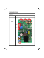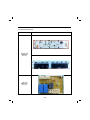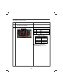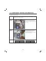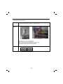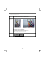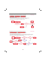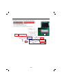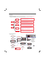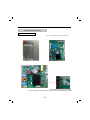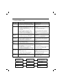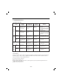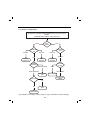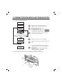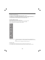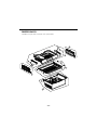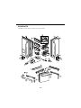
1
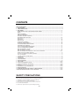
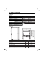
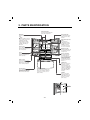
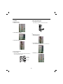
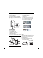
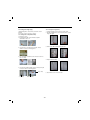
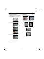
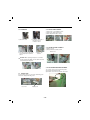
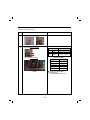
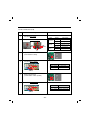
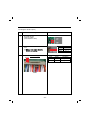
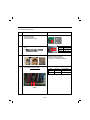
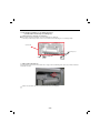
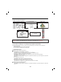
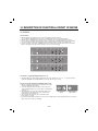
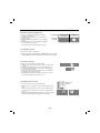
REFRIGERATOR
SERVICE MANUAL
CAUTION
BEFORE SERVICING THE UNIT,
READ THE SAFETY PRECAUTIONS IN THIS MANUAL.
MODEL : LFX31925**
COLOR : STAINLESS(ST)
SMOOTH BLACK(SB)
SUPER WHITE(SW)
CONTENTS
SAFETY PRECAUTIONS ....................................................................................................................................................... 2
1. SPECIFICATIONS ............................................................................................................................................................. 3
2. PARTS IDENTIFICATION ................................................................................................................................................. 4
3. DISASSEMBLY ................................................................................................................................................................ 5-
REMOVING AND REPLACING REFRIGERATOR DOORS .......................................................................... 5
DOOR .............................................................................................................................................................. 6
DOOR ALIGNMENT ....................................................................................................................................... 7
FAN AND FAN MOTOR................................................................................................................................... 7
DEFROST CONTROL ASSEMBLY ................................................................................................................ 7
REFRIGERATOR LIGHT (TOP) .................................................................................................................. 8-9
MULTI DUCT .................................................................................................................................................. 9
DISPENSER ................................................................................................................................................. 10
DISPLAY PCB .............................................................................................................................................. 10
ICE BUTTON ASSEMBLY ............................................................................................................................ 10
WATER BUTTON ASSMEBLY ..................................................................................................................... 10
ICE CORNER DOOR REPLACEMENT ........................................................................................................ 10
ICEMAKER REPLACEMENT ....................................................................................................................... 11
SUB PCB FOR WORKING DISPENSER ..................................................................................................... 11
CAP DUCT MOTOR REPLACEMENT ......................................................................................................... 12
HOW TO REMOVE A ICE BIN ..................................................................................................................... 13
HOW TO INSERT A ICE BIN ........................................................................................................................ 13
HOW TO REMOVE AND REINSTALL THE PULLOUT DRAWER ......................................................... 14-15
WATER VALVE DISASSEMBLY METHOD .................................................................................................................... 16
FAN AND FAN MOTOR DISASSEMBLY METHOD......................................................................................................... 16
PULL OUT DRAWER ...................................................................................................................................................... 17
CAUTION : SEALED SYSTEM REPAIR ......................................................................................................................... 18
4. ADJUSTMENT ................................................................................................................................................................ 19
COMPRESSOR ................................................................................................................................................................ 19
5. CIRCUIT DIAGRAM ........................................................................................................................................................ 20
6. TROUBLESHOOTING .................................................................................................................................................... 21
7. PCB PICTURE ........................................................................................................................................................... 22-23
8. Troubleshooting With Error Display ....................................................................................................................... 24-35
9. Troubleshooting Without Error Display ................................................................................................................. 36-44
10. Reference .................................................................................................................................................................. 35-50
11. COMPONENT TESTING INFORMATION ................................................................................................................. 51-59
12. TROUBLESHOOTING .............................................................................................................................................. 60-72
13. ICEMAKER OPEARTING AND TROUBLE SHOOTING METHOD ......................................................................... 73-76
14. DESCRIPTION OF FUNCTION & CIRCUIT OF MICOM ........................................................................................... 77-80
SAFETY PRECAUTIONS
Please read the following instructions before servicing your refrigerator.
1. Unplug the power before handling any elctrical componets.
2. Check the rated current, voltage, and capacity.
3. Take caution not to get water near any electrical components.
4. Use exact replacement parts.
5. Remove any objects from the top prior to tilting the product.
-2-
1. SPECIFICATIONS
1-1 LFX31925**
●
31 cu.ft.
ITEMS
DOOR DESIGN
SPECIFICATIONS
ITEMS
Side Rounded
3/4
X 36
1/4
X 70
1/4
(WXDXH) 31cu.ft.
SPECIFICATIONS
VEGETABLE TRAY
Clear Drawer Type
DIMENSIONS (inches)
35
COMPRESSOR
Linear
NET WEIGHT (pounds)
158kg (348lb)
EVAPORATOR
Fin Tube Type
COOLING SYSTEM
Fan Cooling
CONDENSER
Spiral Condenser
TEMPERATURE CONTROL Micom Control
REFRIGERANT
R-134a (135 g)
DEFROSTING SYSTEM
Full Automatic
LUBRICATING OIL
ISO10 (280 ml)
Heater Defrost
DEFROSTING DEVICE
SHEATH HEATER
DOOR FINISH
PCM, VCM, Stainless
HANDLE TYPE
Bar
INNER CASE
ABS Resin
INSULATION
Polyurethane Foam
●
REFRIGERATOR
LED Module
FREEZER
LED Module
LAMP
DIMENSIONS
Description
LFX31925**
Depth w/ Handles
A
36 1/4 in
Depth w/o Handles
B
33 3/4 in
Depth w/o Door
C
29 1/2 in
Depth (Total with Door Open)
D
48 1/8 in
Height to Top of Case
E
68 3/4 in
Height to Top of Door Hinge
F
70 1/4 in
Width
G
35 3/4 in
Width (door open 90 deg. w/o handle)
H
40 in
Width (door open 90 deg. w/ handle)
I
45 in
-3-
2. PARTS IDENTIFICATION
LED interior lamps
The interior lamps light up the
inside of the refrigerator.
Dairy product bin
The dairy product bin is
used to preserve dairy
products.
Water filter
The water filter purifies
water.
NOTE
The filter should be replaced
every 6 months. Please refer
to°Replacing the filter°
in this manual for details.
* This function may not be
available, depending on
the model.
Adjustable refrigerator
shelf
The refrigerator
compartment shelves
are adjustable to allow
flexibility for storage
needs. Preserve large
size food or containers.
Indoor ice bin
100 ice cubes are
automatically produced over
per 24-hour period.
Modular door bin
Interchangeable bins can
be arranged to suit your
storage needs.
Crisper
The crisper controls humidity
and helps vegetables and
fruit to stay crisp.
Auto closing hinge
The refrigerator doors
and freezer drawers
close automatically when
you push them slightly.
(The door only closes
automatically when it is
open at an angle of less
than 30°C.)
Fixed door bin
The fixed door bin is used
to preserve chilled food or
drinks that are of a suitable
size for storing in this bin.
Pull out Drawer
It is a convenient feature
that allows you to fill large
containers such as the extra
bin and It is useful to store.
Dura Base® Divider
This is a convenient feature that
allows you to fill large containers,
such as an ice chest, cooler or
pitcher, with ice.
-4-
Glide'N'Serve
When you want to store
food items at a much
lower temperature, you
can use the temperature
controller to maintain the
lowest possible chilling
temperature (without
freezing).
F-Basket
This is a convenient
feature that allows you
to fill small frozen food,
beverage to needed
quick cooling.
3. DISASSEMBLY
3-1 REMOVING AND REPLACING REFRIGERATOR DOORS
●
Removing Refrigerator Door
CAUTION: Before you begin, unplug the refrigerator. Remove food and bins from doors.
▶ Left Door -FIG. 2
1. Disconnect water supply tube by pushing back on the disconnect ring (3).-FIG. 1
2. Open door. Loosen top hinge cover screw (1).
Use flat tip screwdriver to pry back hooks on front underside of cover (2). Lift up cover.
3. Disconnect door switch wire harness and remove the cover.
4. Pull out the tube.
5. Disconnect all 3 wiring harnesses (4). Remove the grounding screw (5).
6. Rotate hinge lever (6) counterclockwise. Lift top hinge (7) free of hinge lever latch (8).
CAUTION: When lifting hinge free from the latch, be careful that door does not fall forward.
7. Lift door from middle hinge pin and remove door.
8. Place the door with the insides facing up, on a not scratch surface.
▶ Right Door -FIG. 3
1.
2.
3.
4.
Open the door, remove 1 screw on the top of the hinge cover. Loosen top hinge cover screw (1). Lift up cover (2).
Disconnect door switch wire harness and remove the cover.
Rotate hinge lever (3) clockwise. Lift top hinge (4) free of hinge lever latch (5).
Lift door from middle hinge pin and remove door.
CAUTION: When lifting hinge free from the latch, be careful that the door does not fall forward.
5. Place the door with the insides facing up, on a not scratch surface.
Figure 2
Figure 3
!
!
"
"
#
#
$
%
&
Figure 1
1) Insert the tube until you can see only one of
the lines printed on the tube.
2) After inserting, pull the tube to ascertain that
it is secure.
3) Assemble clip.
Correct
-5-
Incorrect
3-2 DOOR
●
●
Door Gasket Replacement
1. Insert gasket into channel
Insert and press gasket into channels at doorliner.
Mullion Removal
1. Remove 2 screws.
2. Lift mullion up carefully.
●
Mullion Replacement
1. Connect wire harness.
3. Disconnect wire harness.
2. Insert mullion into channel.
Insert the mullion into channel at door as shown below.
●
Door Gasket Removal
1. Remove gasket
Remove the gasket from gasket channel at doorliner as
shown in the illustration below.
3. Assemble 2 screws.
Gasket
Channel
Gasket
-6-
* Ice Fan Assembly Replacement
3-3 Door Alignment
If the level of refrigerator doors is uneven, follow the
instructions below to align the doors:
Turn the leveling legs (CCW) to raise or (CW) to lower the
height of the front of the refrigerator by using flat blade
screw driver or 11/32" wrench. Use the wrench (Included
with the User Manual) to adjust the bolt in the door hinge to
adjust the height. (CW to raise or CCW to lower the height.)
1) Remove the plastic guide for slides on left side by
unscrewing phillips head screws.
2) Pull out the cover sensor to disassemble by using tools
shown in the figure.
3) Pull out the cover grille to disassemble by using tools
shown in the figure.
4) Put your hand into the inside of grille to disassemble
shown in the figure.
5) Disconnect wire harness of the grille assembly.
6) Remove the Ice fan assembly by loosening all screws.
Down
(1)
(2)
(3)
(4)
(5)
(6)
Up
3-4 FAN AND FAN MOTOR
1. Remove the freezer drawer.
2. Remove the plastic guide for slides on left side by
unscrewing phillips head screws.
3. Remove the grille assembly by removing four screws
and pulling the grille assembly forward.
4. Remove the Fan Motor assembly by loosening 3 screws
and disassembling the shroud.
5. Pull out the fan and separate the Fan Motor and Bracket
Motor.
FAN MOTOR
Shroud
3-5 DEFROST CONTROL ASSEMBLY
Defrost Control assembly consists of Defrost Sensor and
FUSE-M.
The Defrost Sensor works to defrost automatically. It is
attached to the metal side of the Evaporator and senses its
temperature. At 46F(8°C), it turns the Defrost Heater off.
Fuse-M is a safety device for preventing over-heating of
the Heater when defrosting.
1. Pull out the grille assembly. (Figure 1)
2. Separate the connector with the Defrost Control
assembly and replace the Defrost Control assembly after
cutting the Tie Wrap. (Figure 2)
BRACKET
MOTOR
GRILLE ASSEMBLY
Ice Fan Assembly
-7-
DEFROST-CONTROL
ASSEMBLY
3-6 Refrigerator Light (Top)
3-6-2 Refrigerator Light (Side)
Unplug Refrigerator, or disconnect power at the circuit
breaker.
If necessary, remove top shelf or shelves.
1. Unplug refrigerator power cord from electric outlet.
2. Put flat screwdriver into sevice hole and remove cover of
refrigerator light.
3-6-1 Refrigerator Compartment Lamp
1) Release 2 screws.
2) Hold both ends with your both hands and pull it
downward to remove it.
3. Remove the LED assembly from connector.
3) To remove the case lamp and cover lamp, release
another 2 screws as following picture.
4) Use a flat blade screwdriver as shown below to remove
the cover lamp.
4. Replace LED assembly.
5) To remove the LED Assembly, open the Hook part to pull
it out as shown in the following picture.
Case, lamp
5. Assemble the cover in reverse order.
Cover, lamp
LED, Assembly
-8-
3-6-3 Cap Duct LED LAMP(Bottom)
3-7 MULTI DUCT
1. Unplug refrigerator power cord from electric outlet.
2. Open the refrigerator door to need diassembly.
3. Put flat screwdriver into service hole, remove the cover
of cap duct LED LAMP.
1. Remove 2 screws and guide rail.
2. Remove the upper and lower Caps by using a flat
screwdriver and remove 2 screws as shown figure.
4. Remove the LED assembly from connector.
3. Disconnect the lead wire on the bottom position
4. Grip both side of multi duct, pull it out.
5. Replace LED assembly.
6. Assembly the cover in reverse order.
-9-
3-8 DISPENSER
3-10 ICE BUTTON ASSEMBLY
1) Remove the 1 screw holding the lever.
2) Remove the spring from the hook.
3) Push and pull on the tab to remove.
1) Pull out the drain
2) Holding the inner side of
the dispenser pull
forward to remove.
Button Lever
3-11 WATER BUTTON ASSMEBLY
1) Remove screws.
2) Grasp the Button assembly and lift.
3) If nozzle is interfered with button,
push and pull out the bottom of
button.
Button Lever
4) Remove the
lead wire.
CAUTION: When replacing the dispenser cover make
sure the lead wire does NOT come off and the water line
is not pinched by the dispenser.
3-12 ICE CORNER DOOR REPLACEMENT
1) Loosen the front screw as shown in the picture.
2) Lift up the hinge with one hand.
3) Pull out the Ice Corner Door with the other hand.
3-9
DISPLAY PCB
As shown below, remove 1 screw on the PCB fixing screw.
Remove the display PCB fixing screw.
hinge
Case, PCB
Display PCB
- 10 -
CAUTION: Make sure that the motor housing is taped to
the mold, if not positioned correctly the cover will not fit
properly.
3-13 ICEMAKER REPLACEMENT
1) Remove 4 screws as shown.
2) Grasp the bottom of motor cover assembly and pull
slowly.
3-14 SUB PCB FOR WORKING DISPENSER
1) Disconnect the wire harness.
2) Remove 1 screw from PCB and replace with new PCB.
3) Disconnect wire harness from wall of compartment.
In-door
motor
- 11 -
3-15 CAP DUCT MOTOR REPLACEMENT
1) Separate the Housing of the Cap Duct Motor.
2) Unscrew 3 screws to disassemble the motor.
3) When replacing the motor, check the position of the door
duct and the link for proper fit.
Duct Door
Link
Cap Duct Motor
NG Position
4) Insert 2 screws.
5) Push housing aside.
- 12 -
3-16 HOW TO REMOVE A ICE BIN
3-17 HOW TO INSERT A ICE BIN
1) Grip the handles, as shown.
1) Insert the Ice Bin, slightly tilting to avoid touching the
Icemaker. (Especially, Ice-Detecting Sensor)
2) Tilt and lift slightly as shown.
3) Remove ice bin slowly.
- 13 -
3-18 HOW TO REMOVE AND REINSTALL THE PULLOUT DRAWER
3-18-1 Follow Steps to Remove
Step 1) Open the freezer door.
Step 2) Remove the lower basket.
Step 3) Remove the two screws from the guide rails (one
from each side).
Step 4) Removal of the freezer door is done by l ifting clear
of the rail support.
Fully extend both rails.
Step 5) Remove only 1 screw of gearice, and disassemble
the bar and gearice
Step 6) Remove 2 screws of both side of supporter covers
tv and disassemble the supporter cover tv.
- 14 -
3-18-2 Follow Steps to Reinstall
Step 1) Insert both side of supporter cover tv into
connector rails, and then screw them.
Step 2) ① Assemble a bar and gear ice with screw.
② Push the otherside of the gear to inside of the
bar.
Step 3) Put gear ice assembled with the bar by screw into
connector rail’s hole.
Step 4) Insert opposite gear ice into connector rail and
screw them
Step 5) The rail system will align itself by pushing the rails
all the way into the freezer section.
Pull the rails back out to full extension.
Step 6) Reinstall the freezer door by inserting the rail tabs
into the guide rail.
* Assemble them like as pictures
Step 7) Reinstall the two screws into the guide rails
(one from each side).
Step 8) Reinstall the lower basket, and close the freezer
door.
- 15 -
3-19 WATER VALVE DISASSEMBLY METHOD
1) Turn off the water to unit. Remove the waterline from the
valve.
3-20 FAN AND FAN MOTOR DISASSEMBLY
METHOD
1) Remove screws for the Drain Pipe Assembly and the 1
connected to the Motor Cover.
MOTOR COVER
2) Separate the Fan Assembly and Motor, turn counter
clockwise to remove from the motor shaft.
2) Remove cover and 1 screw from the valve.
Mechanical Cover
FAN ASSEMBLY
MOTOR
3) Separate the housing and remove the valve.
Assemble in reverse order. Taking care to avoid.
1. Do not to bend the tube during assembly.
2. Press the Water Dispenser button letting water pour out,
this checks for any leaks in the tube connection, this may
vary depending on the water pressure
( about 2 minutes.).
Housing
4) Remove the clip, and press the collet to separate the
tube from the connector. Note: there maybe some water
in the line.
- 16 -
3-21 PULL OUT DRAWER
Top Drawer
1. Use a flat blade screwdriver to push the tab in on the left rail and push the tab on the right rail in with your finger.
Once the tabs have been pushed in, you can lift the tray up and out.
2. Pull both rails out to the full extension and insert the insert the back of the tray into both rails. Then set the front of the
tray into the rail and push it until you hear it click into place.
Middle Drawer
1. To remove the middle drawer.
Pull the drawer out to full extension. Lift the front of the drawer up, then pull it straight out.
2. To install, slightly tilt up the front and insert the drawer into the frame and push it back into push it back place.
- 17 -
3-22. CAUTION : Sealed System Repair
Before making a sealed system repair : Start with the power cord unplugged from the outlet. Plug in the power cord and
between 6 and 12 seconds after it has been pugged in, unplug it from the power source. this will allow both sides of the 3
way valve to be opened to allow for proper evacuation.
3 Way Valve Service
■ The 3 way valve has plastic parts inside, so always wrap it
with a wet cloth before servicing when using a torch.
1) Always replace the 3 way valve if there is a leak at any one
of the 3 tubes coming from it.
2) Service in replacement of valve (valve failure) Perform
service in the same method as above.
- 18 -
4. ADJUSTMENT
4-1 COMPRESSOR
4-2-3 Compressor protection logic
Since linear Comp conducts linear reciprocating motion,
we have protection logic for compressor, motor and PCB
as the below.
4-1-1 Role
The compressor intakes low temperature and low pressure
gas from the evaporator of the refrigerator and compresses
this gas to high-temperature and high-pressure gas. It then
delivers the gas to the condenser.
4-1-2 Note for Usage
(1) Be careful not to allow over-voltage and over-current.
(2) Do not drop or handle carelessly.
(3) Keep away from any liquid.
If liquid such as oil or water enters the Cover PTC
Compressor may fail due to breakdown of their
insulating capabilities.
(4) Always use the Parts designed for the compressor and
make sure it is properly attached to the compressor.
Parts may appear physically identical but could have
different electrical ratings. Replace parts by part number
and model number. Use only approved substitute parts.
4-1-3 Remove the cover PTC
- Stroke Trip
During the operation, if stroke is above the target value,
decrease the target volt by 3V.
- Current Trip
Current trip is set in order to protect compressor
mechanical part and drive from the overcurrent that might
arise during the operation.
Check the current for every 416.7us and if the Trip
exceeds 1.86Arms more than three times at Comp ON,
forcibly stop and restart six minutes later.
- Lock Piston Trip
If stroke is under 5mm even if the current is more than
14Arms, Take it as ‘piston lock’ and restart after 2’30” of
Comp OFF. Check the current and stroke for every
416.7us and if the condition fits more than three times at
Comp ON, the Trip occurs.
- IPM fault Trip
It occurs if FO signal received from IPM is LOW. For
every 416.7us, check whether FO signal is LOW. The trip
occurs if it is found three times during the five
periods(83ms).
(1) Remove the Cover Back M/C
(2) Remove two screws on comp base
(3) Use a L-shaped flap tooll to pry off the cover
(4) Assembly in reverse order of disassembly
- 19 -
5. CIRCUIT DIAGRAM
- 20 -
6. TROUBLESHOOTING
6-1 Error Code Summary
WARNING: When checking Resistance values, make sure to
turn off the power, and wait for the voltage to
discharge.
NOTE) Within 3 hours after the error : Press the Ice Plus button and Freezer button simultaneously
3 hours after the error : All errors, except for "Er rt", "Er SS",
"Er IS(except for Icing sensor)", "Er gF", "Er It" error, are displayed.
"Er IS" which is displayed without input of user is the error of Icing Sensor.
FRESH AIR FIL TER
Error Display
NO
Error Detection
Category
1
Normal
2
3
4
Freezer Sensor
Error
Refrigerator
Sensor Error
Defrosting
Sensor Error
Freezer
Refrigerator
Temperature Temperature
(Error code ) (Error code )
Er
FS
Er
rS
Er
dS
Error Generation Factors
Remark
None
Normal operation of Display
Short or Disconnection
of Freezer Sensor
Short or Disconnection
of Refrigerator Sensor
Short or Disconnection
of Defrosting Sensor
Check each sensor at it’s
connector.
5
Icing Sensor
Error
Er
IS
6
Pantry sensor
error
Er
SS
Short or disconnection of
the sensor about Ice maker
(Icing sensor, Ice maker
sensor)
Short or Disconnection
of Pantry Sensor
7
Room Temp
Sensor Error
Er
rt
Short or Disconnectoin of
Room temp.sensor
8
Ice maker kit
defect
Er
It
Other Electric system error
such as moter, gear, Hall IC,
operation circuit within I/M kit
When the ice does not drop
even when the I/M Test S/W
is pressed
9
Flow
Meter(Sensor)
Defect
Er
gF
Error of flow meter or water
input or low water pressure
Error of flow meter or water
input or low water pressure or
flow meter connection
10
Poor Defrosting
Er
dH
Even though it is passed
1 hour since then Defrosting,
if Defrosting sensor is not
over 46°F(8°C), it is caused
Temperature Fuse
Disconnection, Heater
disconnection, DRAIN Jam,
Poor Relay for Heater
11
Abnormality of
BLDC FAN Motor
for Ice Making
Er
IF
It is caused when feedback
signal isn’t over 65 seconds
during BLDC FAN motor
operating
Poor BLDC Motor connection,
DRIVE IC, and TR
12
Abnormality of
BLDC FAN Motor
for Freezer
Er
FF
It is caused when feedback
signal isn’t over 65 seconds
during BLDC FAN motor
operating
Poor BLDC Motor connection,
DRIVE IC, and TR
13
Abnormality of
BLDC FAN
MOTOR For
Refrigerator
Er
rF
It is caused when feedback
signal isn’t over 65 seconds
during BLDC FAN motor
operating
Poor BLDC Motor connection,
DRIVE IC, and TR
14
Abnormality of
BLDC FAN Motor
for Mechanic
Room
Er
CF
It is caused when feedback
signal isn’t over 65 seconds
during BLDC FAN motor
operating
Poor BLDC Motor connection,
DRIVE IC, and TR
CO
Communication Error
between Micom of Main PCB
and Display Micom
Poor Communication
connection,Poor TR of
Transmitter and Receiver
Tx/Rx between display and
main board.
15
Communication
Error
Er
- 21 -
7. PCB PICTURE
7-1 Main PCB
P/No & MFG
Picture
CON5
EBR730936
(2011.01~)
CON3
CON2
CON1
- 22 -
CON6
CON7
7-2 Display PCB & Sub PCB
P/No
Picture
Display PCB
EBR 729554
(2011.03~)
Sub PCB
EBR60070709
(2011.01~)
- 23 -
8. Troubleshooting With Error Display
8-1 Freezer Sensor Error (Er FS)
No
Checking flow
1
Check for a loose connection.
2
Check the Blue/White to
Blue/White.
Result & SVC Action
Result
SVC Action
0Ω
Short
Change the sensor
OFF
Open
Replace the refrigerator
Other
Normal
Check the Temp and
resistance (Table-1)
<Temperature table-1>
<CON7>
(1) To (2)
Result
-22°F / -30°C
40 ㏀
-13°F / -25°C
30 ㏀
-4°F / -20°C
23 ㏀
5°F / -15°C
17 ㏀
14°F / -10°C
13 ㏀
23°F / -5°C
10 ㏀
32°F / 0°C
8㏀
※ The sensor is determined by
the temperature.
For example, 23㏀ indicates -4°F.
- 24 -
8-2 Refrigerator Sensor Error (Er rS)
No
Checking flow
1
Check for a loose connection.
2
Check the White to White.
Result & SVC Action
Result
SVC Action
0Ω
Short
Change the sensor
OFF
Open
Replace the refrigerator
Other
Normal
Check the Temp and
resistance (Table-2)
<Temperature table-2>
<CON7>
(1) To (2)
Result
23°F / -5°C
38 ㏀
32°F / 0°C
30 ㏀
41°F / 5°C
24 ㏀
50°F / 10°C
19.5 ㏀
59°F / 15°C
16 ㏀
※ The sensor is determined by
the temperature.
For example, 30㏀ indicates 32°F.
- 25 -
8-3 Icing Sensor Error (Er IS)
No
Checking flow
1
Check for a loose connection.
2
Check the Blue to Blue.
Result & SVC Action
Result
SVC Action
0Ω
Short
Change the sensor
OFF
Open
Replace the refrigerator
Other
Normal
Check the Temp and
resistance (Table-1)
<Temperature table-1>
<CON5>
(1) To (2)
Result
-22°F / -30°C
40 ㏀
-13°F / -25°C
30 ㏀
-4°F / -20°C
23 ㏀
5°F / -15°C
17 ㏀
14°F / -10°C
13 ㏀
23°F / -5°C
10 ㏀
32°F / 0°C
8㏀
※ The sensor is determined by
the temperature.
For example, 23㏀ indicates -4°F.
- 26 -
8-4 Defrost Sensor Error (F dS)
No
Checking flow
1
Check for a loose connection.
2
Check the Orange to Orange.
Result & SVC Action
Result
Check the Brown to Brown.
SVC Action
0Ω
Short
Change the sensor
OFF
Open
Replace the refrigerator
Other
Normal
Check the Temp and
resistance (Table-3)
<Temperature table-3>
(1) To (2)
Result
23°F / -5°C
38 ㏀
32°F / 0°C
30 ㏀
41°F / 5°C
24 ㏀
50°F / 10°C
19.5 ㏀
59°F / 15°C
16 ㏀
※ The sensor is determined by
the temperature.
For example, 23㏀ indicates -4°F.
<CON7>
- 27 -
8-5 Defrost Sensor Error (R dS)
No
Checking flow
1
Check for a loose connection.
2
Check the Orange to Orange.
Result & SVC Action
Result
SVC Action
0Ω
Short
Change the sensor
OFF
Open
Replace the refrigerator
Other
Normal
Check the Temp and
resistance (Table-3)
<Temperature table-3>
Check the Gray to Gray.
(1) To (2)
Result
23°F / -5°C
38 ㏀
32°F / 0°C
30 ㏀
41°F / 5°C
24 ㏀
50°F / 10°C
19.5 ㏀
59°F / 15°C
16 ㏀
※ The sensor is determined by
the temperature.
For example, 23㏀ indicates -4°F.
<CON7>
- 28 -
8-6 Defrost Heater Error (F dH)
No
1
Checking flow
Result & SVC Action
Check the Door gasket.
Part
2
Check the Defrost control part.
Fuse
M
3
Input Test 3 Mode.
(Push the button 3 times)
4
Check the Blue to Orange.
SVC Action
0Ω
Go to the 3
Other
Change Fuse-M
Def’
Heater
34~42 Ω
Go to the 3
Other
Change Fuse-M
Def’
Sensor
22 ㏀↑
Go to the 3
OFF
Replace product
Fuse-M
Def’
Heater
Def’
Heater
Result
Result
SVC Action
112 ~ 116 V
Go to the 5
0V
Replace Main PCB
Result
SVC Action
0V
Explain to customer
112 ~ 116 V
Replace Main PCB
<CON3>
5
Release the test mode.
push the button 1 times. (normal)
6
Check the Blue to Orange.
<CON3>
- 29 -
8-7 Defrost Heater Error (R dH)
No
1
Checking flow
Result & SVC Action
Check the Door gasket.
Part
2
Check the Defrost control part.
SVC Action
0Ω
Go to the 3
Other
Change Fuse-M
Def’
Heater
34~42 Ω
Go to the 3
Other
Change Fuse-M
Def’
Sensor
22 ㏀↑
Go to the 3
OFF
Replace product
Fuse-M
Def’
Heater
Def’
Heater
Result
Fuse
M
3
Input Test 3 Mode.
(Push the button 3 times)
4
Check the Blue to Yellow.
Result
SVC Action
112 ~ 116 V
Go to the 5
0V
Replace Main PCB
Result
SVC Action
0V
Explain to customer
112 ~ 116 V
Replace Main PCB
<CON3>
5
Release the test mode.
push the button 1 times. (normal)
6
Check the Blue to Yellow.
<CON3>
- 30 -
8-8 Refrigerator Fan Error (Er rF)
No
Checking flow
Result & SVC Action
1
Reset the unit and
Input Test 1 Mode.
(Push the button 1 time)
2
Open the freezer door and Check the air
flow.
※ While an error code is displayed,
the fan is not working.
4
Status
SVC Action
No windy
Go to 3
Windy
Go to 4
Check the Fan motor voltage.
(3) (2) (1)
<CON6>
- 31 -
Point
Result
SVC Action
(1) ~ (2)
Below 12 V
Change the PCB
(1) ~ (3)
0 or 5 V
Change the motor
8-9 Freezer Fan Error (Er FF)
No
Checking flow
Result & SVC Action
1
Reset the unit and
Input Test 1 Mode.
(Push the button 1 time)
2
Open the freezer door and Check the air
flow.
※ While an error code is displayed,
the fan is not working.
3
Check the Fan motor.
4
Check the Fan motor voltage.
Status
SVC Action
No windy
Go to 3
Windy
Go to 4
Rotate fan using your hand.
It feel sticky, change the motor.
(cause of ice or rust inside of motor)
(3) (2) (1)
<CON7>
- 32 -
Point
Result
SVC Action
(1) ~ (2)
Below 12 V
Change the PCB
(1) ~ (3)
0 or 5 V
Change the motor
8-10 Icing Fan Error (Er IF)
No
Checking flow
Result & SVC Action
1
Reset the unit and
Input Test 1 Mode.
(Push the button 1 time)
2
Open the freezer door and Check the air
flow.
※ While an error code is displayed,
the fan is not working.
3
Check the Connector.
(Frozen caused the PCB short)
4
Check the Fan motor voltage.
(3) (2) (1)
<CON7>
- 33 -
Status
SVC Action
No windy
Go to the 3,4
Windy
Go to the 5
Point
Result
SVC Action
(1) ~ (2)
Below 9 V
Change the PCB
(1) ~ (3)
0 or 5 V
Change the motor
8-11 Condenser Fan Error (Er CF)
No
Checking flow
1
Reset the unit and
Input Test 1 Mode.
(Push the button 1 time)
2
Check the fan rotating.
Result & SVC Action
※ While an error code is displayed,
the fan is not working.
3
Check the Fan motor and surrounding.
4
Check the Fan motor voltage.
(3) (2) (1)
<CON7>
- 34 -
Status
SVC Action
No windy
Check motor
Windy
Go to the 4
Rotate fan using your hand.
It feel sticky, change the motor.
Point
Result
SVC Action
(1) ~ (2)
Below 10 V
Change the PCB
(1) ~ (3)
0 or 5 V
Change the motor
8-12 Communication Error (Er CO)
No
Checking flow
1
Check the loose connection.
2
Check the Red to White/Red.
Result & SVC Action
CON101
<Display>
3
12 V
Go to the 3
Other
Check the Hinge
(loose connection)
Change the Main PCB
Result
SVC Action
0 or 5 V
Change the Display PCB
Other
Go to the 4
Result
SVC Action
0 or 5 V
Change the Main PCB
Other
Go to the 5
Result
SVC Action
0 or 5 V
Change the Display PCB
Other
Go to the 6
Result
SVC Action
0 or 5 V
Change the Main PCB
Other
Explain to customer
<CON101>
<CON101>
Check the White/Black to White/Red.
CON101
<Display>
5
SVC Action
Check the Orange to White/Red.
CON101
<Display>
4
Result
<CON101>
Check the White/Red to Orange.
<CON5>
6
Check the White/Red to White/Black.
<CON5>
- 35 -
9. Troubleshooting Without Error Display
9-1 Cube mode doesn’t work
No
Checking flow
1
Check the loose connection.
2
Check the Black to White.
(While pushing the lever S/W)
Result & SVC Action
Lever s/w
Result
SVC Action
112 ~ 115 V
Go to the 3
Other
Change PCB
Not
pushing
0~2V
Go to the 3
Other
Change PCB
Lever s/w
Result
SVC Action
9 ~ 12 V
Go to the 4
Other
Change PCB
Not
pushing
0~2V
Go to the 4
Other
Change PCB
Point
Result
SVC Action
31.1 ~ 42.1 Ω
Explain
Other
Replace
Geared Motor
9.9 ~ 12.1 Ω
Explain
Other
Replace
Geared Motor
Pushing
<CON2>
3
Check the RED to White Red.
(While pushing the lever S/W)
Pushing
<CON3>
4
<CON1>
Check the resistance value.
(1) to (2)
(3) to (4)
<Ice Maker>
(1)
(2)
(3)
(4)
<Dispenser Motor>
- 36 -
9-2 Crush mode doesn’t work
No
Checking flow
1
Check the loose connection.
2
Check the Sky Blue to White.
(While pushing the lever S/W)
Result & SVC Action
Lever s/w
Result
SVC Action
112 ~ 115 V
Go to the 3
Other
Change PCB
Not
pushing
0~2V
Go to the 3
Other
Change PCB
Lever s/w
Result
SVC Action
9 ~ 12 V
Go to the 4
Other
Change PCB
Not
pushing
0~2V
Go to the 4
Other
Change PCB
Point
Result
SVC Action
31.1 ~ 42.1 Ω
Explain
Other
Replace
Geared Motor
9.9 ~ 12.1 Ω
Explain
Other
Replace
Geared Motor
Pushing
<CON2>
3
Check the Black to White Red.
(While pushing the lever S/W)
Pushing
<CON3>
4
<CON1>
Check the resistance value.
(1) to (2)
(3) to (4)
<Ice Maker>
(1)
(2)
(3)
(4)
<Geared Motor>
<Dispenser Motor>
- 37 -
9-3 Water mode doesn’t work
No
Checking flow
Result & SVC Action
1
Check the loose connection.
2
Check the Purple to White.
(While pushing the lever S/W)
Lever s/w
Result
SVC Action
112 ~ 115 V
Go to the 3
Other
Change PCB
Not
pushing
0 ~2 V
Go to the 3
Other
Change PCB
Point
Result
SVC Action
360 ~ 420Ω
Explain
Other
Replace
Water Valve
360 ~ 420Ω
Explain
Other
Replace
Water Valve
Pushing
<CON2>
3
Check the resistance value.
(1) (2)
(3) (4)
(1) to (2)
(3) to (4)
<Pilot Valve>
Dispenser Ice Maker
<Water Valve>
Machine Room
In door
- 38 -
9-4 Freezer room lamp doesn’t work
No
Checking flow
1
Check the Freezer door switch.
2
Check the door S/W resistance.
Result & SVC Action
If feel sticky, Change the door s/w.
Status
Result
SVC Action
0Ω
Go to the 3
not
Change door S/W
Push
S/W
Infinity
Go to the 3
Other
Change door S/W
Status
Result
SVC Action
12 V
Go to the 4
Other
Change the PCB
Result
SVC Action
12 V
Go to the 5
Other
Change the LED Lamp
Result
SVC Action
0~2V
Explain to customer
Other
Change the Door S/W
12 V
Explain to customer
Other
Change the LED Lamp
Normal
3
Check the Red/yellow to Pink.
Normal
<CON7>
4
Check the Red to Black.
Status
Normal
5
Check the Black to White.
Status
Closed
Open
- 39 -
9-5 Refrigerator room lamp doesn’t work
No
Checking flow
1
Check the Refrigerator door switch.
2
Check the door Switch resistance.
Result & SVC Action
If feel sticky, Change the door s/w.
Status
Result
SVC Action
0Ω
Go to the 3
Other
Change door Switch
Push
S/W
Infinity
Go to the 3
Other
Change door Switch
Status
Result
SVC Action
12 V
Go to the 4
Other
Change the PCB
Result
SVC Action
12 V
Go to the 5
Other
Change the LED Lamp
Result
SVC Action
0~2V
Explain to customer
Other
Change the Door S/W
12 V
Explain to customer
Other
Change the LED Lamp
Normal
3
Check the Red/yellow to Pink.
Normal
<CON7>
4
Check the Red to Black.
Status
Normal
5
Check the Black to Blue.
Status
Closed
Open
- 40 -
9-6 Poor cooling in Fresh food section
No
1
Checking flow
Result & SVC Action
Check the sensor resistance.
<CON7>
※ The sensor is determined by
the temperature.
For example, 30㏀ indicates 32°F.
2
Reset the unit and
Input Test 1 Mode.
(Push the button 1 time)
3
Open the fresh food door and Check the
air flow.
5
Check the air temperature.
Cold or not ?
- 41 -
Temperature
Result
23°F / -5°C
38 ㏀
32°F / 0°C
30 ㏀
41°F / 5°C
24 ㏀
50°F / 10°C
19.5 ㏀
59°F / 15°C
16 ㏀
Status
SVC Action
Windy
Go to the 4
No windy
Check the R Fan motor
Check the damper
(Go to the 6)
Status
SVC Action
Cold
Explain to customer
Not cold
Check the Compressor
And sealed system
No
6
Checking flow
Result & SVC Action
Check the R Fan motor voltage.
(3) (2) (1)
<CON6>
- 42 -
Point
Result
SVC Action
(1) ~ (2)
Below 12 V
Change the PCB
(1) ~ (3)
0 or 5 V
Change the motor
9-7 Poor cooling in Freezer compratment
No
1
Checking flow
Result & SVC Action
Check the sensor resistance.
<CON7>
※ The sensor is determined by
the temperature.
For example, 23㏀ indicates -4°F.
2
Reset the unit and
Input Test 1 Mode.
(Push the button 1 time)
3
Open the freezer door and Check the air
flow.
4
Check the air temperature.
Cold or not ?
- 43 -
(1) To (2)
Result
-22°F / -30°C
40 ㏀
-13°F / -25°C
30 ㏀
-4°F / -20°C
23 ㏀
5°F / -15°C
17 ㏀
14°F / -10°C
13 ㏀
23°F / -5°C
10 ㏀
32°F / 0°C
8㏀
Status
SVC Action
Windy
Go to the 4
No windy
Check the F Fan motor
Status
SVC Action
Cold
Explain to customer
Not cold
Check the Compressor
And sealed system
No
6
7
Checking flow
Result & SVC Action
Check the Fan motor.
Rotate fan using your hand.
It feel sticky, change the motor.
(cause of ice or rust inside of motor).
Point
Result
SVC Action
Motor
Sticky
Change the motor
Point
Result
SVC Action
(1) ~ (2)
Below 12 V
Change the PCB
(1) ~ (3)
0 or 5 V
Change the motor
Check the F Fan motor voltage.
(3) (2) (1)
<CON7>
- 44 -
10. Reference
10-1 TEST MODE and Removing TPA
1. How to make TEST MODE
If you push the test button on the Main PCB, the refrigerator will be enter the TEST MODE.
* 1 time : Comp / Damper / All FAN on
(All things displayed)
* 2 times : Damper closed
(22 22 displayed)
* 3 times : Forced defrost mode
(33 33 displayed)
Main PCB
2. How to remove Terminal Position Assurance (TPA)
<AC TPA>
<DC TPA>
※ After measure the values, you should put in the TPA again.
- 45 -
10-2 TEMPERATRUE CHART - FREEZER AND ICING SENSOR
TEMP
RESISTANCE
VOLTAGE
-39°F (-40°C)
73.29 ㏀
4.09 V
-30°F (-35°C)
53.63 ㏀
3.84 V
-30°F (-21°C)
39.66 ㏀
3.55 V
-13°F (-25°C)
29.62 ㏀
3.23 V
-4°F (-20°C)
22.33 ㏀
2.89 V
5°F (-15°C)
16.99 ㏀
2.56 V
14°F (-10°C)
13.05 ㏀
2.23 V
23°F (-5°C)
10.10 ㏀
1.92 V
32°F (0°C)
7.88 ㏀
1.63 V
41°F (+5°C)
6.19 ㏀
1.38 V
50°F (+10°C)
4.91 ㏀
1.16 V
59°F (+15°C)
3.91 ㏀
0.97 V
68°F (+20°C)
3.14 ㏀
0.81 V
77°F (+25°C)
2.54 ㏀
0.67 V
86°F (+30°C)
2.07 ㏀
0.56 V
95°F (+35°C)
1.69 ㏀
0.47 V
104°F (+40°C)
1.39 ㏀
0.39 V
- 46 -
10-3 TEMPERATRUE CHART - REFRIGERATOR AND DEFROST SENSOR
TEMP
RESISTANCE
VOLTAGE
-39°F (-40°C)
225.1 ㏀
4.48 V
-30°F (-35°C)
169.8 ㏀
4.33 V
-30°F (-21°C)
129.3 ㏀
4.16 V
-13°F (-25°C)
99.30 ㏀
3.95 V
-4°F (-20°C)
76.96 ㏀
3.734 V
5°F (-15°C)
60.13 ㏀
3.487 V
14°F (-10°C)
47.34 ㏀
3.22 V
23°F (-5°C)
37.55 ㏀
2.95 V
32°F (0°C)
30 ㏀
2.67 V
41°F (+5°C)
24.13 ㏀
2.40 V
50°F (+10°C)
19.53 ㏀
2.14 V
59°F (+15°C)
15.91 ㏀
1.89 V
68°F (+20°C)
13.03 ㏀
1.64 V
77°F (+25°C)
10.74 ㏀
1.45 V
86°F (+30°C)
8.89 ㏀
1.27 V
95°F (+35°C)
7.40 ㏀
1.10 V
104°F (+40°C)
6.20 ㏀
0.96 V
- 47 -
Compressor Troubleshooting
Step 1) Open PCB cover
Step 2) Check for blinking frequency of LED, PCB
If compressor is normal, it does not blink
: Refer to the next page to find out what actions to take according to how many times LED blink
- 48 -
Actions to take according to Led blinking frequency
No
LED operating condition
Cause
LED two - time repetiton
PCB part
defect
(piston
overrun)
1
on - on - off - on - on - off - on - on - off
repeating
on - on - on - on - off - on - on - on - on - off
outlet
clogging
piston
constraint
1. After resetting
power, check if it is
running normal
2. If the same
symptom arises after
the first action,
replace PCB
3. If the same
symptom arises after
the second action,
replace compressor
repeating
LED five - time repetiton
3
on - on - on - on - on - off - on - on - on - on - on - off
repeating
LED six - time repetiton
4
on - on - on - on - on - on - off - on - on - on - on - on - on - off
1. After resetting
power, check if it is
running normal
If the same symptom
circuit
arises after the first
overcurrent action, replace PCB
error
If the same symptom
repeating
arises after the
second action,
replace compressor
LED seven- time repetiton
5
on - on - on - on - on - on - on - off - on - on -on - on - on - on- on - off
- 49 -
1.After resetting
power, check if it is
running normal
2.If the same
symptom arises after
the first action,
replace PCB
1.After resetting
power, check if it is
running normal
2.If the same
symptom arises after
the first action,
replace PCB
3.If the same
symptom arises after
the second action,
replace compressor
LED four - time repetiton
2
Service guideline
repeating
PCB part
defect
(IPM)
1.After resetting
power, check if it is
running normal
2. If the same
symptom arises after
the first action,
replace PCB
10-4 How to check the Fan-Error
After sending a signal to the fan, the MICOM checks the BLDC fan
motor s lock status. If there is no feedback signal from the BLDC fan,
the fan motor stops for 10 seconds and then is powered again for 15
seconds. To determine that there is a fan motor malfunction,
this process is repeated 3 times. If the fan motor is determined to be
defective, the error code will be shown in the display for 30 minutes.
At this point, the process will be repeated until the fan motor operates
normally. If normal operation is achieved, the error display is erased and
the MICOM is reset automatically.
No signal
Error Display
15s
Normal drive
15s
10s
15s
10s
No signal
Repeat
20s
Pause 30min
15s
10s
15s
10s
20s
Pause 30min
- 50 -
10s
11. COMPONENT TESTING INFORMATION
11-1 Defrost Controller Assembly
Function
The controller assembly is made up of two different kinds of parts. The fuse and the sensor.
To determine if these parts are defective, check for resistance. The fuse will cut power to the
defrost heater at very high temperatures.
How to
Measure
(Fuse-M)
Set a ohmmeter to the 2 housing pin.
Measure the 2 pin connected to Fuse-M.
If the ohmmeter indicate below 0.1ohm
fuse-m is a good condition, But if infinite the
part is bad.
(1) to (2)
How to
Measure
(Sensor)
Set a ohmmeter to The 2housing pin.
Measure the 2 pin connected to Sensor.
If the ohmmeter indicate 11㏀ (at room
temperature) Sensor is good.
When check the ohm at other temperatures
Check the sensor manual.
(1) to (2)
Standard
Fuse-M (at all temperature)
Sensor (at room temperature)
Test Point
Ressult
Test Point
Ressult
(1) to (2)
0 ~ 0.1Ω
(1) to (2)
11Ω
- 51 -
11-2 Sheath Heater (Freezer Room)
Function
Sheath heater is the part for defrost. All heating wire is connected to only one line. So we
can decide part is defective or not when we check the resistance.
How to
Measure
(1) (2)
Set a ohmmeter connect to The housing pins.
Measure the pins connected to Sheath Heater.
If the ohmmeter indicates (V°øV)/Watt=R is on a good condition,
ex) watt=350W, voltage=115V R=(115°ø115)/350=38Ω
Infinitive value implies sheath heater is disconnected.
Standard
Sheath heater (at all temperature)
Test Point
Ressult
(1) to (2)
41.8 ~ 46.2
- 52 -
11-2 Sheath Heater (Refrigerator Room)
Function
Sheath heater is the part for defrost. All heating wire is connected to only one line. So we
can decide part is defective or not when we check the resistance.
How to
Measure
(1)
Set a ohmmeter connect to The housing pins.
Measure the pins connected to Sheath Heater.
If the ohmmeter indicates (V°øV)/Watt=R is on a good condition,
ex) watt=350W, voltage=115V R=(115°ø115)/350=38Ω
Infinitive value implies sheath heater is disconnected.
Standard
Sheath heater (at all temperature)
Test Point
Ressult
(1) to (2)
78.6 ~ 86.8
- 53 -
(2)
11-4 Door Switch
Function
The switch senses if the door is open or closed.
- When the door open, lamp on.
- When the door open, the switch give information to Micom.
When the door open, internal contact operate on and off moving plunger of door switch up
and down.
How to
Measure
<Switch, Freezer>
<Switch, Refrigerator>
Button
(Plunger)
1
2
3
3
4
1
4
2
2
Beep
Beep
Check the resistance between connectors 1, 2 and 3, 4 .It means
check whether or not applying an electric current. If there is
resistance, the switch is good.
Standard
Multimeter beep – Switch F,R
Nomal
Push the button(Plunger)
Beep or 0Ω
None (∞Ω)
- 54 -
3
1
4
11-5 Dispenser DC Motor
Function
- Dispenser DC Motor : When customer push the dispenser button, Pull duct door and
abstract from ice bank.
How to
Measure
(1)
(2)
Dispensor DC Motor
Standard
Dispenser DC Motor
Test Points
Result
(1) to (2)
9.9 ~ 12.1Ω
- 55 -
11-6 AC Motor ASSEMBLY
Function
The motor in the door pushed the ice into the dispenser.
How to
Measure
< In-door Motor >
(1)
< In-door Motor >
1 Separate the
housing.
1 Separate the
housing.
2 Measure the
resistance between
(1) and (2)
2 Measure the
resistance between
(1) and (3)
(2)
(1)
(3)
Check the resistance between connectors (In-door motor 1, 2) and
(In-door motor 1, 3). It means check whether or not applying an
Electric current. If there is resistance, it means the geared motor or
solenoid is not inferiority
Standard
Geared Motor
Cube Solenoid
Test Points
Result
Test Points
Result
(1) to (2)
31.1 ~ 42.09Ω
(1) to (3)
31.1 ~ 42.09Ω
- 56 -
11-7 Damper
Function
The damper supplies cold air from the freezer to the chill room using the damper plate. The
chill room is colder when the damper plate is open. When the damper is closed the chill
rooms temperature will rise.
How to
Measure
< Damper Circuit >
1
Blue
1
2
Blue
Red
3
3
White
White
Check the
3 Yellow
1 , 3
< extension >
Check the 2 , 4
Check the
1 , 3
Check to see if there is electrical current, if there is resistance the damper is good.
Standard
Damper
Test Points
Result
Test Points
Result
Red and Yellow
373 ~ 456Ω
Blue and White
373 ~ 456Ω
- 57 -
11-8 Lamp Socket
Function
The lamp socket connect cover lamp assembly to lamp.
The lamp socket fix lamp and unite lamp and cover lamp assembly.
The lamp socket supply electric source to lamp also.
How to
Measure
(1)
(2)
(3)
(4)
Check the resistance between connector of housing and connector of lamp socket. It means
check whether or not applying an electric current.
If there is resistance it means the lamp socket is good.
Standard
Test Points
Result
(1) to (2) and (3) to (4)
0Ω
- 58 -
11-9 Flow Sensor
Function
Flow Sensor (in machine room)
Count the water quantity from city water to water filter in refrigerator
How to
Measure
Flow Sensor
(in machine room)
Standard
Test Points
Result
Red wire to Black wire
4 ~ 30 kΩ
- 59 -
12. Compressor Troubleshooting
PCB Check (Simplify)
Protection Logic
TEST 1 Mode
A-inverter
Con201
Disconnect
Power Off
Y
Time>30sec
& V≒200
Power On
PCB OK
N
Replace Driver PCB
Check Voltage about 200V
past 30second after turn on
Test Mode
Comp
Ref.
TEST1
Display & sound
FC75(A-Inverter)
Forced Starting
TDC (Full Stroke)
Refer
Display ON, Buzz 1 time
Troubleshooting
LED blink 1
Reset
LED blink 1
Replace Driver PCB
LED blink 7
Reset
LED blink 7
LED blink 5
Reset
LED blink 5
LED
Blink?
Replace Driver PCB
N
Reset
Not
Cooling
Y
Comp.
Check?
Recheck
Comp.
Work?
Y
Comp.
Check?
N
N
Replace Comp.
Y
Heavy Repair
N
LED blink2
Reset
Y
Leakage?
Comp.
Work?
LED blink2
N
Recheck
N
Harness
Check?
Y
Comp.
Check?
N
Y
Fix Harness
Y
Heavy Repair
Reset
LED blink6
LED blink6
Check C
Refrigerant
leak?
N
Comp.
Work?
N
Recheck
Comp.
Check?
N
Y
Heavy Repair
Comp.
Work?
N
Y
Leakage?
IPM output
>
80V-20%
Y
Heavy Repair
Y
Refrigerant
leak ?
Y
N
- 60 -
Recheck
N
Recheck
N
Comp.
Check?
Replace Driver PCB
N
N
12-1 Check A
- There is PC Board located in the PCB case.
The control driver is PC board for the compressor.
- This step shows the source voltage of the driver PC board.
Step1. Open PCB Cover
Step2. Check Driver PCB
* Driver PCB located in machine room.
- 61 -
IPM Output check
- Measure the voltage between the POWER and COMM pins of the connector as shown below.
Check to make sure compressor is receiving voltage from IPM
- In order to determine whether the compressor is operating normally,
check the output voltage during the refrigeration cycle.
Multi
Tester
A-Inverter
- After initial power-up, when the compressor begins to operate, wait 10
minutes before checking.
- The compressor is operating normally if the voltage is greater than 80V.
- 62 -
12-2 Check B
B1. LED blinks once, then repeats (FCT0 Fault: A-Inverter)
Blink
Protection Logic
OFF Blink OFF
- Purpose: Detecting motor current and voltage error
- Check voltage at point A (Motor Voltage), point B (Motor Current) and Point C (Capacitor
Voltage) when compressor is off.
- Spec: Points A, B, & C 2.5V ± 0.3V
Protection
logic
Check B
Blink 1 time
(FCT 0) Check B1
Y
Out of spec?
(2.2 - 2.8V)
Replace Driver PCB
N
Reset Power
B2. LED blinks two times, then repeats (Stroke Trip: A & E Inverters)
Blink
Protection Logic
Blink OFF Blink Blink OFF
- Purpose: Prevent abnormally long piston strokes.
- Case 1. If compressor doesn’t work and LED blinks - Cause: Possibly harness from compressor to PCB might be
defective.
- Case 2. If compressor works intermittently and LED blinks - Cause: Condenser Fan or Freezer Fan is not running. Sealed
system problem such as moisture restriction, restriction at capillary tube or refrigerant leak.
- Logic: Compressor is forced to off and then tries to restart after 1 minute.
Protection
logic
Check B
Blink 2 times
(Stroke Trip) Check B2
N
Replace
Driver PCB
N
Y
Harness
Connecting
Check C
Y
Compressor
Doesn’t work
Fix Harness
Compressor
Works Intermittently
Y
Capacitor
Spec.
Check C
OK
Fix
Cycle
NG
Y
Cycle
Check E
Repeat
Check Procedure
N
N
Replace
Capacitor
Y
Reset
Power
Stroke Trip
Occur?
Compressor
Damage
Check C
Y
- 63 -
N
Replace
Compressor
B3. LED blinks five times, then repeats (Locked Piston: A & E Inverters)
Protection Logic
Blink Blink Blink Blink Blink OFF
- Purpose: To detect locked piston
- Cause: Lack of oil to the cylinder, cylinder or piston damaged and or restricted discharge.
A Locked Piston can also be caused by foreign materials inside the compressor.
- Logic: Compressor is forced off and tries to restart within 2.5 minutes.
Protection
logic
Check B
Replace
Compressor
Blink 5 times
(Lock Piston Trip) Check B3
N
Compressor
Doesn’t work
Y
Compressor
Doesn’t work
Reset
Power
Hi side
restriction
Y
Sealed
system
Repair
N
Repeat
Check Procedure
B4. LED blinks six times, then repeats (Current Trip: A & E-Inverters)
Blink
-
Blink Blink Blink Blink Blink
Protection Logic
OFF
Purpose: Prevent over-current (overload protect)
Cause: Ambient temperature is high (over 43°C) and/or refrigerator’s condenser air movement is restricted.
Condenser Fan is stopped, restricted discharge line, compressor is damaged, or IPM device is defective.
Logic: Compressor is forced off and tries to restart after 6 minutes.
Protection
logic
Check B
Compressor
Intermittently
works
Blink 6 time
(Current Trip) Check B4
Y
Capacitor
Spec.
Check C2
N
Y
Fix
Cycle
Replace
Driver PCB
Cycle
Check E
Repeat
Check Procedure
NG
Replace
Capacitor
Y
IPM
Check B5
Y
Y
N
NG
Reset
Power
Current trip
Occur?
Compressor
Damage
Check C3
Y
- 64 -
NG
Replace
Compressor
B5. LED blinks seven times, then repeats (IPM Fault: A & E Inverters)
Blink
-
Protection Logic
Blink Blink Blink Blink Blink Blink OFF
Purpose: Prevent high current due to IPM Short
Cause: Damaged IPM (Dead Short)
Test for a dead short at Point A with a VOM.
Logic: Compressor is forced off and tries to restart in 20 seconds.
Protection
logic
Check B
A
Blink 7 times
(Lock Piston Trip) Check B5
Compressor
Doesn’t work
Y
Check IPM
visual inspection
(turn off)
Short
Test
Point A
Replace
Drive PCB
Y
Modify
N
Power
Reset
N
Compressor
Damage
Check C3
- 65 -
Y
NG
Repeat
Check Procedure
Replace
Compressor
12-3 Check C
C1. Harness Connection Check
C2. Capacitor Specifications
C3. Compressor Check
Check Process
- Step 1. Power off. Step 2. Check capacitor spec. (table1). Step3. Check resistance of point A
Step 4. Check wire harness (INF ohm). Step 5. Check resistance at point B. Step 6. Point D.
Y
Check
Capacitor
Spec.
Power
off
Check
wiring to
compressor
Y
Resistance
at Point A
6~8ohm
N
Resistance
at Point B
6~8ohm
N
Resistance
at Point D
6~8ohm
N
Harness
Connecting
OK
Y
N
Replace
Compressor
N
Check Compressor
terminals
Y
Harness
Problem
Y
Y
Problem
B~D
Problem
A~B
Caution : Turn off power during check C
- Measure the resistance at each point except point C
- Dead short check: measure the resistance between power line in compressor and earth ground in refrigerator (Inf. Ohm)
Multi
Tester
Multi
Tester
A
D
B
N/C
Po
Resistance
Co
C
FC75LBNA
* Because of ambient temperature or operating
situations, the values shown can have a slight
deviation.
Capacitor Spec.
450V, 18μF±5%
Multi
Tester
Dead short check
Po: Power
Co: Common
N/C: Open terminal
Earth
P
Multi
Tester
C
- 66 -
Hermetic terminal
12-4 Check D
D1. Activate Protection logic
Cycle check with protection logic
- We have to check Condenser fan and Freezer fan before performing Check D
- Locked Piston, Current trip and stroke trip can be activated by other problems then the driver or compressor.
High Pressure
Side
Restricted
→ When process line on compressor is opened, and refrigerant is not expelled
because it has accumulated in condenser.
→ If fault is corrected after refrigerant is recaptured from sealed system, change
dryer.
Locked piston
Low
Side
Restriction
→ Low side restriction can cause a stroke trip.
→ If fault is corrected after refrigerant is recaptured, perform a sealed
system evacuation and dryer replacement.
Stroke trip
Over charging
Refrigerant
→ Check Suction line
→ If refrigerant is overcharged and suction line temperature is lower
than ambient temperature (about 5~10 degrees) or frost is present
150mm from where the suction line enters the compressor..
Low side
Refrigeration
leak
→ Temp. of compressor and discharge line is normal to slightly higher.
High side pressure is normal to slightly higher than normal
conditions. This is because condenser cannot condense the air
that is trapped in the condenser. The high side pressure and
temperature will not mimic the low side pressures and
temperatures.
Current trip
→ Customer complains of longer run times and poor cooling performance.
→ Lack of refrigerant can, in some incidents, cause piston over travel.
→ Pressure of refrigerant cycle is usually higher than ambient pressure,
therefore oil will flow out with the refrigerant at leak point.
Refrigerant leak
D2. sealed system diagnosis
Sealed system
- Check as follows;
Check for Oil leaks
In machine compartment
Yes
Repair leak
at point where
Oil is present.
No
Check for oil
Remaining in drip tray
In/Out Leakage
Yes
Check for Oil leakage
at each joint
of the Evaporator
No
A
Evaporator
Leakage
A
Replace
Evaporator
A
Check Temp of
Discharge line
and Condenser
A
No
Is there frost
on Suction Line?
Check frost status
Of Evaporator
Yes
No
Frost only
Evaporator inlet
Welding point
1. Comp process stub,
2. Comp discharge
3. Hot Line inlet
4. Drier inlet
5. Drier outlet
6. Evaporator inlet
7. Evaporator outlet
8. suction pipe
Heat Inlet tubing
using heat gun.
No
Is frost pattern
uniform?
Comp,Cond T >
Ambient temp+5deg
Yes
Is frost patern
Uniform?
Yes
Sealed System
is OK
Sealed System
is OK
A
Heavy repair
- 67 -
Yes
OK
No
A
Compressor Troubleshooting
WARNING HIGH VOLTAGE
Step 1) Open PCB cover
Step 2) Check for blinking frequency of LED and PCB
When compressor is normal, it does not blink
: Refer to the next page to find out what actions to take according to how many times LED blink
- 68 -
No
LED operating condition
LED two - time repetiton (Stroke Trip)
1
on - on - off - on - on - off - on - on - off
repeating
Cause
Service guideline
PCB Parts
defect or
Compress
or
Connector
miss
connecting
(Piston
over run)
1. Please check, Whether
connector of
compressor is attached
rightly or not. after
power off
2. After the first action,
You check on normal
operation of
compressor.
3. If the same symptom
arises after the second
action, replace PCB
Piston
constraint
1. After resetting power,
check if it is running
normal
2. If the same symptom
arises after the first
action
3. If the same symptom
arises after the second
action, replace
compressor
LED five - time repetiton (Piston Lock Trip)
2
on - on - on - on - on - off - on - on - on - on - on - off
repeating
LED six - time repetiton (Current Trip)
3
on - on - on - on - on - on - off - on - on - on - on - on - on - off
LED seven- time repetiton (IPM Fault Trip)
4
on - on - on - on - on - on - on - off - on - on -on - on - on - on- on - off
- 69 -
Circuit
over
current
error
repeating Or cycle
error
1. After resetting power,
check if it is running
normal
2. If the same symptom
arises after the first
action
3. If the same symptom
arises after the second
action, replace
compressor
1. After resetting power,
check if it is running
PCB parts
normal
defect
2. If the same symptom
(IPM)
arises after the first
repeating
action, replace PCB
12-5 SERVICE DIAGNOSIS CHART
COMPLAINT
POINTS TO BE CHECKED
Is the power cord unplugged from the outlet?
Check if the power switch is set to OFF.
Check if the fuse of the power switch is shorted.
Measure the voltage of the power outlet.
REMEDY
•
•
•
•
Plug into the outlet.
Set the switch to ON.
Replace the fuse.
If the voltage is low, correct the wiring.
No Cooling.
•
•
•
•
Cools poorly.
• Check if the unit is placed too close to the wall.
• Check if the unit is placed too close to the stove,
gas cooker, or in direct sunlight.
• Is the ambient temperature too high or the room
door closed?
• Check if food put in the refrigerator is hot.
• Did you open the door of the unit too often or
check if the door is sealed properly?
• Check if the Control is set to Warm position.
• Place the unit about 4 inches (10 cm) from
the wall.
• Place the unit away from these heat sources.
• Lower the ambient temperature.
Food in the
Refrigerator
is frozen.
• Is food placed in the cooling air outlet?
• Check if the control is set to colder position.
• Is the ambient temperature below 41°F(5°C)?
• Place foods in the high-temperature section.
(front part)
• Set the control to Recommended position.
• Set the control to Warm position.
Condensation
or ice forms
inside the unit.
• Is liquid food sealed?
• Check if food put in the refrigerator is hot.
• Did you open the door of the unit too often or
check if the door is sealed properly?
• Seal liquid foods with wrap.
• Put in foods after they have cooled down.
• Don't open the door too often and close it
firmly.
Condensation
forms in the
Exterior Case.
• Check if the ambient temperature and humidity of
the surrounding air are high.
• Is there a gap in the door gasket?
• Wipe moisture with a dry cloth. It will
disappear in low temperature and humidity.
• Fill up the gap.
There is
abnormal noise.
• Is the unit positioned in a firm and even place?
• Adjust the Leveling Screw, and position the
refrigerator in a firm place.
• Remove the objects.
• Are any unnecessary objects placed in the back
side of the unit?
• Check if the Drip Tray is not firmly fixed.
• Check if the cover of the compressor enclosure in
the lower front side is taken out.
Door does not
close well.
• Check if the door gasket is dirty with an item like
juice.
• Is the refrigerator level?
• Is there too much food in the refrigerator?
Ice and foods
smell
unpleasant.
● Other
• Check if the inside of the unit is dirty.
• Are foods with a strong odor unwrapped?
• The unit smells of plastic.
• Put in foods after they have cooled down.
• Don't open the door too often and close it
firmly.
• Set the control to Recommended position.
• Fix the Drip Tray firmly in the original position.
• Place the cover in its original position.
• Clean the door gasket.
• Position in a firm place and level the Leveling
Screw.
• Make sure food stored in shelves does not
prevent the door from closing.
• Clean the inside of the unit.
• Wrap foods that have a strong odor.
• New products smell of plastic, but this will go
away after 1-2 weeks.
possible problems:
Check if frost forms
in the freezer.
Not
defrosting
Check Components of
the defrosting circuit.
Check the
refrigeration system.
The system
is faulty.
Perform sealed
system repair.
Check the
Thermistor.
The operation of the
Thermistor is incorrect.
Replace the
Thermistor.
- 70 -
12-6 REFRIGERATION CYCLE
▼ Troubleshooting Chart
TEMPERATURE
OF THE
COMPRESSOR
STATE OF
THE UNIT
STATE OF THE
EVAPORATOR
PARTIAL
LEAKAGE
Freezer
compartment and
Refrigerator don't
cool normally.
Low flowing sound of
Refrigerant is heard
and frost forms in
inlet only.
A little higher than
ambient
temperature.
• Refrigerant level is low due
to a leak.
• Normal cooling is possible by
restoring the normal amount
of refrigerant and repairing
the leak.
COMPLETE
LEAKAGE
Freezer
compartment and
Refrigerator don't
cool normally.
Flowing sound of
refrigerant is not
heard and frost isn't
formed.
Equal to ambient
temperature.
• No discharging of
Refrigerant.
• Normal cooling is possible by
restoring the normal amount
of refrigerant and repairing
the leak.
PARTIAL
CLOG
Freezer
compartment and
Refrigerator don't
cool normally.
Flowing sound of
refrigerant is heard
and frost forms in
inlet only.
A little higher than
ambient
temperature.
• Normal discharging of the
refrigerant.
• The capillary tube is faulty.
WHOLE
CLOG
Freezer
compartment and
Refrigerator don't
cool.
Flowing sound of
refrigerant is not
heard and frost isn't
formed.
Equal to ambient
temperature.
• Normal discharging of the
Refrigerant.
Cooling operation
stops periodically.
Flowing sound of
refrigerant is not
heard and frost melts.
Lower than ambient • Cooling operation restarts
temperature.
when heating the inlet of the
capillary tube.
COMPRESSION
Freezer and
Refrigerator don't
cool.
Low flowing sound of
refrigerant is heard
and frost forms in
inlet only.
A little higher than
ambient
temperature.
• Low pressure at high side of
compressor due to low
refrigerant level.
NO COMPRESSION
No compressing
operation.
Equal to ambient
temperature.
• No pressure in the high
pressure part of the
compressor.
CAUSE
LEAKAGE
CLOGGED BY DUST
MOISTURE CLOG
DEFECTIVE
COMPRESSION
Flowing sound of
refrigerant is not
heard and there is
no frost.
REMARKS
12-6-1 Cleaning
There is no need for routine condenser cleaning in normal Home operating environments. If the environment is
particularly greasy or dusty, or there is significant pet traffic in the home, the condenser should be cleaned
every 2 to 3 months to ensure maximum efficiency.
If you need to clean the condenser:
● Remove
the mechanical cover.
a vacuum cleaner with a soft brush to clean the grille, the open areas behind the grille and the front
surface area of the condenser.
● Replace the mechanical cover.
● Use
- 71 -
12-6-2 SEALED SYSTEM DIAGNOSIS
“Not Cooling” Complaint
All components operating, No airflow problems, Not frosted up as a defrost
problem
problem has been isolated to sealed system area
Frost
Pattern?
Partial
None
Equalization
Test
Equalization
Test
Very Fast
Very Slow
Very Slow
Very Fast
Fast
Inefficient
Compressor
Partial
Restriction
Complete
Restriction
Condenser
Temperature
Cap Tube
Sound
Hotter than Normal
Faint
Room Temperature
None to Weak
Air/Low Side
Leak
Loss of Change
Compressor Not
Pumping
Trace of Oil
Yes
No
Leak
Undercharge
(The equalization test is trying to restart a compressor using a start kit after it has been operating.)
- 72 -
13. ICEMAKER OPERATING METHOD AND TROUBLE SHOOTING
13-1 Icemaker’s Basic Operating Method
Power On
Start Position
• Adjusts Ice Tray to Start Position with power on.
• Waits until water becomes ice.
For cold air circulation, Ice tray will be
on a slightly tilt one hour after
ice-making mode begins. Atilt ice tray
means icemaker’s normal operation.
Icemaking
Mode
Full Ice
Check
Ice Tray on a slightly tilt
• If water becomes ices in the ice tray, Ice-detecting
sensor check if the ice bin is full.
Full Ice?
Harvest
Mode
• Twist the ice tray to drop ice into the ICE BIN.
• Supply water to the ice tray by operating the solenoid
valve.
Fill
• To force water to supply to the ice tray, or check
icemaker’s condition press and hold the FILL Key for
about 3seconds.
In the test mode, The icemaker will run through 3
stages step by step
: Harvest
Fill water
Ice making
Test Mode
To reset the icemaker’s operation, set the power switch OFF position and back it to ON position.
Power
Switch
Ice Tray
Ice-detecting sensor
Icemaker Unit
- 73 -
13-2 ICE MAKER FUNCTIONS
13-2-1 Icemaking Mode
1. Icemaking Mode begins right after the ice tray fills with water.
2. Icemaker waits until water becomes ice in the ice tray.
Ice-detecting sensor checks if the ice bin is full every 2min.
13-2-2 Harvest Mode
At least in 110min, since icemaker begun icemaking mode, Icemaker starts to twist the ice tray to drop ices into the Ice bin.
(After installation, at least 1day is needed to make ices)
If the icemaker never drop ices to the ice bin though water becomes ices in the ice tray, check the real temperature of
compartment. (not temperature on display)
Icemaker needs below 0°F to drop ices to ice bin.
13-2-3 Fill/Park Position
Once the normal harvest mode has been completed, the water solenoid will be activated.
13-3 Trouble Shooting Ice & Water system Issues
13-3-1 Icemaker not making ice or not making enough ice (Environmental Diagnosis)
Icemaker can’t make ices itself. Basically, water, temperature and time are needed.
- Water : If no Water, then no Ice.
- Temperature : The compartment, where the icemaker is located, has to be at least 1°F so that icemaker dumps ices to
the bin.
- Time : At least 80 minutes must be passed to make one series of ices after water comes into icemaker.
Test Mode should not be carried out before checking below.
Not making ice
Water
Is Icemaker’s tray filled
with water or Ice?
Temperature
Yes
Is measured
temperature below 10°F
in the icemaker
compartment
Time
No
Check saddle valve.
1. Is saddle valve turned on?
2. Is the icemaker fill tube frozen?
Check the fill tube heater’s electrical
resistance.
3. Are water valve housings are connected properly?
Check all the water valve’
connection.
4. Water line kinked or damaged?
5. Is water filter too old?
1. Does cold air come out from air vent normally?
No
Check if Icing fan is working.
Check if multi duct is blocked.
Measure the temp. and Check gas leakage
2. Are the R & F room cold enough?
at the back.
3. Does icemaker compartment door close tightly?
Yes
How long has customer
waited for icemaker to
make ices?
No
1. At least 120min. must be passed to make ices after water comes into icemaker.
2. At least 24 hours must be passed to have ice bin full of ices. (not in case of
installation)
If the issue haven’t resolved yet, though you have checked all the items above, go to next step.
- 74 -
13-3-2 Icemaker not making ice or not making enough ice
(Icemaker Unit & Ice-detecting sensor Diagnosis)
Icemaker Unit and Ice-detecting sensor Diagnosis
The icemaker unit and Ice-detecting sensor is programmed to be diagnosed.
Follow the procedure step by step to check to see if icemaker and Ice-detecting sensor is working normally.
Icemaker Unit
Ice-detecting sensor
Fill Key
1st STEP (Icemaker Unit Diagnosis)
Press the fill key for about 3sec. If the icemaker runs 2 stages of harvest and filling water step by step, It means icemaker’s
mechanism is normal.
Caution : Be sure that the ice tray is not filled with water before pressing fill key.
- 75 -
2st STEP (Ice-detecting sensor Diagnosis)
1. Remove Ice bin from compartment
2. Close the left door
(Door switch pushed)
3. Wait for 3min.
4. Freezer door stays open
5. Push the refrigerator
button & lock button at the
same time.
FRESH AIR FIL TER
If ETY is shown on the display after the procedure above, Ice-detecting sensor is normal.
If FULL is shown on the display after the procedure above, Ice-detecting sensor is abnormal.
ETY = empty
13-3-3 Icemaker not making ice or not making enough ice (Other Suspected Items)
Strongly suspect items below If the issue remains yet, though all the diagnosis for icemaker has been carried out.
- Cap duct bad sealing
- Defective thermal sensor in the icemaker compartment
- Not cold icemaker compartment area (sealed system)
13-3-4 Not Dispensing Ice
Clogged Ice In the Ice Bin (suspected items)
- Customer haven’t used ice dispenser over a week.
Resolution : the ices gets stuck if customer doesn’t use ice dispenser.
In this case, empty the ice bin and wait until the new ices are stacked in the ice bin.
- Temperature of icemaker compartment is not cold enough.
Resolution : Check ice fan, sealed system, cap duct, vent and other items related to temperature.
- Cap duct doesn’t seal the air properly.
Resolution : Possibly, warm air could get into the compartment and make ices get stuck. Replace the cap duct with
new one.
- In-door geared motor doesn’t work
Resolution : Change the in-door geared motor and test it.
- The water comes out of fill cup and the water get into the ice bin.
Resolution : The water pressure from shutoff valve is too high.
Recommend to use regulator to the customer and close the shutoff valve slightly.
Clogged Ices In the Chute (suspected items)
- Cap duct doesn’t seal the air properly.
Resolution : Possibly, warm air could get into the compartment and make ices get stuck. Replace the cap duct with
new one.
- 76 -
14. DESCRIPTION OF FUNCTION & CIRCUIT OF MICOM
14-1 FUNCTION
14-1-1 Function
FRESH AIR FIL TER
FRESH AIR FIL TER
FRESH AIR FIL TER
1. When the appliance is plugged in, it is set to 37°F for Refrigerator and 0°F for freezer.
You can adjust the Refrigerator and the Freezer control temperature by pressing the ADJUST button.
2. When the power is initially applied or restored after a power failure, it is set to Control temperature Previously.
3. If you do not press any button after turning on the power, only CRUSH or CUBE Label that has been selected will be
turned on and all other LEDs on the display Panel will be turned off within 60 seconds. (Power Save Mode)
4. If you press a button, only CRUSH, CUBE label and Lock icon that has been selected will be turned on and all other
LEDs on the display Panel will be turned off within 20 seconds. (Power Save Mode)
14-1-2 How to Toggle the Display between °F & °C
1. The initial setting is °F and the display temperature mode can be changed from °F to °C or °C to °F by pressing and
holding the FRZ TEMP and the REF TEMP keys at the same time for over 5 seconds.
14-1-3 Lock function (dispenser and display button lock)
1. When the refrigerator is first turned on, the buttons are not locked.
“LOCK” is deactivated with no light on.
2. To lock the display, the dispenser, and the control panel, press
and hold the LOCK button for 3 seconds. “LOCK” is activated with
“Lock Icon” on.
3. The LOCK button is the only control feature that remains active
Ex) In selecting
Ex) In selecting
in the locked state. The buzzer sound, other control buttons,
"LOCK"
"LOCK" again
and the dispenser are deactivated.
4. To release from the locked state, press and hold the LOCK
button again for 3 seconds.
5. If you don’t hold the Alarm/Lock button more than 3 seconds, Alarm function will be changed and alarm for opened door
will be on/off same as alarm icon indicating.
- 77 -
14-1-4 Filter condition display function
1. There is a replacement indicator light for the filter
cartridge on the dispenser.
2. Water filter needs replacement once six months or of
using water filter.
3. When the Water Filter Icon blinks, you must exchange
the filter.
4. After replacing the filter, press and hold the Light/Filter
button for more than 3 seconds.
After then water Filter icon turn off with reset status.
Classification
In initial Power On
/ Filter RESET
Filter Status
Display
14-1-5 Air Filter selection
Please select this function for Air Filter.
• When you press the Air Filter Button, the “POWER” will be turned on again.
• Air Filter POWER function automatically turns off after a fixed time passes.
14-1-6 Ice Plus selection
1. Please select ice plus function for quick freezing.
2. When you press the ice plus button, the ice plus icon will be turned
on again.
3. Ice plus function automatically turns off after a fixed time passes.
4. If you want additional power save, you can turn on energy saving
(some heater off for anti-dew).
5. To turn on or off the energy saving function, press Ice plus/Energy
saving Button for more than 3 seconds.
6. We recommend using energy saving function when you go out for
quite a long time and are out of the rainy season.
14-1-7 Dispenser use selection
WATER PAD
ICE PAD
You can select water or ice by separated pad switch.
• When you press ice type button, ice type will be changed. (Crush or
Cube)
• Hold your cup in the dispenser for a few seconds after dispensing
ice or water to allow the last pieces of ice drops of water to fall into
the cup.
• When after initially establ ishing the water comes out, the water tank
inside fills and until at the time of quality the hour is caught.
- 78 -
Blinking
14-1-8 CONTROL OF FREEZER FAN MOTOR
1. Freezer fan motor has high and standard speeds.
2. High speed is used at power-up, for Ultra Ice, and when refrigerator is overloaded.
Standard speeds is used for general purposes.
3. To improve cooling speed, the RPM of the freezer fan motor change from normal speed to high.
4. High speed (2700RPM) : Initial power on or load corresponding operation, Ultra Ice.
Normal speed (2400RPM) : General working conditions.
14-1-9 Cooling Fan Motor
1. The cooling fan is switched ON and OFF in conjunction with the compressor.
2. The cooling fan Motor has high and standard speeds. (When room temper rapture more high then 38°C speed is high)
3. The Failure sensing method is the same as in the fan motor of the freezing fan motor(refer to failure diagnosis function
table for failure display).
14-1-10 Ice Compartment Fan
1. The Icing Fan is controlled by the the sensor on the top of the ice compartment.
2. The Failure sensing method is the same as in the fan motor of the freezer
(refer to failure diagnosis function table for failure display)
14-1-11 Refrigeration room Fan Motor
1. The refrigeration room fan is switched ON and OFF in conjunction with the refrigeration room temperature.
2. The Failure sensing method is the same as in the fan motor of the freezing fan motor (refer to failure diagnosis function
table for failure display).
14-1-12 Ice PLUS
1.
2.
3.
4.
The purpose of this function is to intensify the cooling speed of freezer and to increase the amount of ice.
Whenever selection switch is pressed, selection/release, the Icon will turn ON or OFF.
If there is a power outage and the refrigerator is powered on again, Ice PLUS will be canceled.
To activate this function, press the Ice PLUS key and the Icon will turn ON. This function will remain activated for 24 hrs.
The first one hour the compressor, Freezer Fan and Icing Fan will be ON. The next 23 hours the Ice room will be
controlled at the lowest temperature. After 24 hours or if the Ice PLUS key is pressed again, the Ice room will return to its
previous temperature.
5. During the first hour :
(1) Compressor, Freezer Fan and Icing Fan run continuously.
(2) If a defrost cycle begins during the first 30 minutes of Ice Plus, the Ice PLUS cycle will complete its cycle after
defrosting has ended.
If the defrost cycle begins when Ice Plus has run for more than 30 minutes, Ice PLUS will run for 40 minutes after the
defrost is completed.
(3) If Ice PLUS is pressed during defrost, Ice Plus Icon is on but this function will start seven minutes after defrost is
completed and it shall operate for three hours.
(4) If Ice Plus is selected within seven minutes after compressor has stopped, the compressor (compressor delays
seven minutes) shall start after the balance of the delay time.
6. For the rest of the 23 hours, the Ice room will be controlled at the lowest temperature.
14-1-13 How to set the display mode and cancel it
1. With the refrigerator door open, keep pressing the Refrigerator Temp Button and ICE PLUS Button more than 5 seconds,
then it goes to the display mode with Special Beep Sound With Special Beep Sound.
2. Perform the same way again to cancel the display mode.
3. All Freezing unit will be turned off at display mode (Exceptions : Lamp, Display)
- 79 -
14-1-14 Defrosting (removing frost)
1. Defrosting starts each time the COMPRESSOR running time Betwee 7~50 hours.
2. For initial power on or for restoring power, defrosting starts when the compressor running time reaches 4 hours.
3. Defrosting stops if the sensor temperature reaches 46.4°F(8°C) or more. If the sensor doesn’t reach 46.4°F(8°C) in 1
hours, the defrost mode is malfunctioning. (Refer to the defect diagnosis function, 8-1-15.)
4. Defrosting won’t function if its sensor is defective (wires are cut or short circuited)
14-1-15 Defect Diagnosis Function
1.
2.
3.
4.
Automatic diagnosis makes servicing the refrigerator easy.
When a defect occurs, the buttons will not operate; but the tones. such as ding. will sound.
When the defect CODE removes the sign, it returns to normal operation (RESET).
The defect CODE shows on the Refrigerator and Freezer Display.
FRESH AIR FIL TER
* Display check function:
If simultaneously pressing Ultra Ice button and freezing temperature adjustment button for a
second, display LCD graphics on. If releasing the button, the LCD graphic displays the previous
status.
You can check the error code Within 3-hour Period from initial error
14-1-16 Auto pantry
1. The temperature control will automatically start upon the selected Auto Pantry temperature control.
2. You can adjust the Pantry control with three different temperature ranges by pressing the Temp.Selector button.
- 80 -
15. EXPLODED VIEW & REPLACEMENT PARTS LIST
CASE PARTS
CAUTION : Use the part number to order part, not the position number.
603C
603E
S03
626A
503E
624E
207B
624G
402A
624C
S11
503D
500P
S01
409D
158A
103B
S01
271B
103A
501F
610F
S11
S03
B01
207A
S02
402A
282G
406D
610D
120A
629A
631B
409H
B01
628A
631A
405J
405E
S02
405K
410J
271D
327B
S10
500A
145B
145A
404C
405G
411A
120B
405L
S11
313A
262B
S11
405I
409F
S14
406B
302B
B02
262H
400A
105A
302C
249D
619D
318A
316B
317A
316A
S14
105D
408A
401A
303A
314A
249C
B02
106A
300A
304A
106A
312C
327B
405H
312D
408B
404A
306A
310B
405B
329A
303C
403B
332C
405F
301A
405C
305B
308B
305C
407A
410G
315A
305B
305C
- 81 -
610C
FREEZER PARTS
CAUTION: Use the part number to order part, not the position number.
145C
S04
131A
249M
136C
136B
133C
249L
132Q
S04
136E
134A
133C
145F
132P
237C
136A
- 82 -
REFRIGERATOR PARTS
CAUTION: Use the part number to order part, not the position number.
141H
142B
141A
143A
142A
142D
141F
141B
141H
141A
141H
141A
141F
141F
141B
141B
141D
154A
161B
151C
161C
151A
161C
161A
151B
146E
162B
145D
162A
- 83 -
DOOR PARTS
CAUTION: Use the part number to order part, not the position number.
241A
231B
233B
233A
231A
241C
235A
241K
212G
B06
B06
241B
241K
241F
241G
241E
312B
241F
241E
B06
243C
243D
B06
619B
243A
603B
262C
244A
603C
615A
243B
244A
624A
619C
405M
262E
262C
409I
405M
409I
253A
250B
250A
200A
S05
249E
241L
250B
B06
212D
B06
249J
S05
201A
203A
249F
249K
- 84 -
DISPENSER PARTS
CAUTION: Use the part number to order part, not the position number.
276A
276G
276F
276I
405A
276B
275A
278C
279A
278D
402E
279K
402C
279L
501D
279B
500C
281A
501A
279C
- 85 -
VALVE & WATER TUBE PARTS
CAUTION: Use the part number to order part, not the position number.
617A
625A
616G
616D
616G
623B
S31
616J
623B
616J
616F
627B
603C
616D
S31
S31
627A
619A
619E
603B
- 86 -
ICE MAKER & ICE BIN PARTS
CAUTION: Use the part number to order part, not the position number.
630J
630J
612A
630F
630B
630C
600A
611A
607A
630A
630H
630D
606A
630E
630Q
630G
- 87 -
P/No. MFL62188047
MAR., 2011 Printed in Korea