1
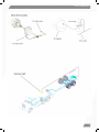
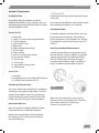
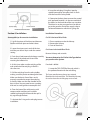
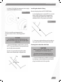
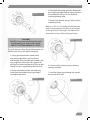
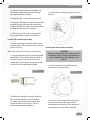
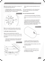
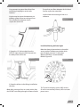
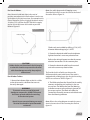
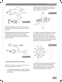
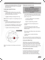
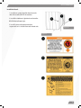
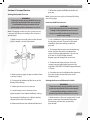
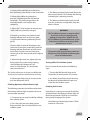
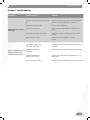
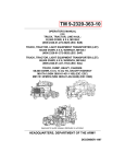
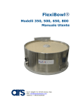
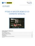
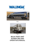
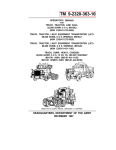
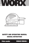
INSTALLATION MANUAL
1
INSTALLATION MANUAL
Section 1: General Information
Checking for Air Leaks...................................................... 18
OEM and Retrofit...................................................................3
System Description...............................................................3
Section 6: Troubleshooting
Section 2: System Components
Questions and Answer..................................................... 20
Pressure Protection Valve...................................................5
Control Unit Assembly.........................................................5
Red On/Off Ball Valve...........................................................5
Air Dryer and Filter................................................................5
Air Pressure Regulator.........................................................5
Pressure Differential Switch...............................................5
Axle Plug...................................................................................5
Rotary Union Assembly.......................................................5
Flex Hoses................................................................................5
Indicator Light........................................................................5
Section 3: Preparation
Installation Tools....................................................................6
Identifying Trailer Axle Type..............................................6
Section 4: Installation
Installation Procedures........................................................7
Installing the Axle Air Fitting.............................................8
Cleaning the Axle Tube Interior.......................................9
Installing the Axle Plug Assembly................................ 10
Installing the Rotary Union Assembly........................ 10
Installing the System Control Unit............................... 11
Pressure Protection Valve (PPV).................................... 11
Airlines.................................................................................... 11
Installing the Warning Indicator Light........................ 12
System Operation Check................................................. 14
Installing the System Flex Hoses................................... 15
Checking the System for Leaks...................................... 15
Lubricating the Wheel-Ends........................................... 15
Installing the Decals.......................................................... 16
Section 5: Use and Service
Setting the System Pressure........................................... 17
Incorrect Cold Tire Pressure............................................ 17
Setting the Pressure Differential Switch.................... 17
Checking operation of the Indicator Light................ 18
Turning Off the Tire Inflation System.......................... 18
2
INSTALLATION MANUAL
Section 1: General Information
About This Manual
The procedures detailed in this manual describe:
• Installing the automatic tire inflation system
on a new trailer at the Original Equipment
Manufacturer (OEM)
• Retrofitting the automatic tire inflation system
on an existing fleet trailer
Before You Begin
This manual provides installation and maintenance
procedures for the Automatic Tire Inflation
System. Use the procedures in the manual
to install the tire inflation system on either new
trailer axles at original equipment manufacturers
(OEM) or in-service trailer axles at fleets.
A low pressure warning indicator mounted on
the trailer informs the driver that a tire is losing
air and is being filled by the on-board system.
A series of filters and check valves isolate the tires
from each other so that each tire is monitored
and serviced individually.
A pressure protection valve (PPV) is located
downstream of the trailer reserve tank and
upstream of the control valve. The PPV provides
separate and independent isolation from the
trailer air brake system, if the reserve tank pressure
falls below the safe level. The PPV assures
the integrity of the braking performance of the
vehicle at all times by closing the PPV.
A pressure regulator in the system controls the
pre-set tire pressure as recommended by the
customer’s tire manufacturer.
Read and understand all instruction and procedures
before you begin to service components.
Read and observe all Caution and Warning safety
alerts that precede instructions or procedures
you will perform. These alerts help to avoid damage
to components, serious personal injury, or
both.
Follow your company’s maintenance and service,
installation, and diagnostics guidelines.
Access Product and Service Information on Our
Website visit www.tireinflation.com.
System Description
The Automatic Tire Inflation System is a commercial
tire monitoring, maintenance and inflation
system that is permanently mounted to the
trailer to fill, maintain and warn a truck operator
of the loss of trailer tire pressure.
The system delivers air to a leaking tire during
vehicle operation.
3
INSTALLATION MANUAL
Control Unit
4
INSTALLATION MANUAL
Section 2: System Components
Pressure Differential Switch
Pressure Protection Valve (PPV)
A flow-sensing Pressure Switch in the Control
Unit Assembly makes electrical contact through the
wiring harness and activates the warning indicator
light when pressure drops in the regulator.
The Pressure Protection Valve (PPV) is mounted
downstream of the trailer’s reserve air tank to
allow separation from other trailer functions. This
valve will open if the system is pressurized and
functioning properly. This valve also controls the
air supply to the regulator.
Control Unit Assembly
The Control Unit Assembly controls the operation,
pre-set tire pressure setting and warning sensitivity
of the tire inflation system.The Control Unit
Assembly contains a Shut-off Valve, Filter, Air
Pressure Regulator and Pressure Switch.
Red On/Off Ball Valve
The Shut-off Ball Valve controls the air supply from
the Trailers air tank to the regulator that controls the
tire inflation system.
In the OFF position, with the valve in perpendicular
position, airflow is disabled.
In the ON position, in line with the valve air line,
airflow is enabled.
Air Dryer and Filter
The regulator filter prevents moisture and
contaminants from entering the Control Unit
Assembly. However, we recommend using an
auxiliary truck-mounted air dryer in conjunction
with the 10-micron filter with a semi-automatic drain
valve. This filter should be serviced during scheduled
maintenance.
Axle Plug
An Axle Plug is installed in the spindle bore. A
Stator is threaded into the center of the axle
plug. The stator has a filter that filters the axle air
as it passes through the axle tube just before the
air enters the tire.
Rotary Union Assembly
The Rotary Union assembly is threaded directly
into the hubcap and provides an air distribution
point between the stationary axle and the rotating
hub. The rotary union then passes air through
flexible hoses to both tires to maintain the pre-set
tire inflation pressure.
Flex Hoses
The flexible wheel-end hoses distribute air from
the rotary union to each tire via the valve stem.
Each hose contains an internal check valve, and
senses the individual tires air pressure, in each
tire. This ensures that each tire is checked
independently of the others.
Indicator Light
The warning indicator includes a light mounted
on the driver side of the trailer and is visible by the
driver in the cab mirror. The warning indicator is
illuminated when the system senses a pressure drop
as air flows to the low tire on the trailer.
Air Pressure Regulator
The Pressure Regulator is preset at the factory to
the customer’s preferred cold tire pressure setting.
5
INSTALLATION MANUAL
Section 3: Preparation
Installation Tools
1.75 ID, or 2.75 ID
Determine the axle type from the placard located
on the axle.
No specialty tools are needed to install the
automatic tire inflation system. However there are
some tools to have handy that will allow for a faster
and more efficient install.
Once you have identified this measurement, follow
the installation procedures in this manual.
General Tool List
1. Power drill
2. 2 each 11/32-inch carbon-tipped drill bits
3. 7/16-inch drill bit
4. 1/8-inch NPT-27 tap
5. Teflon tape
6. 80 grit sandpaper flap wheel
7. 8-ft. PVC pipe
8. Torque wrench
9. 2mm or 5/64-inch Allen wrench
10. Screw driver (Phillips)
11. Oil catch pan
12. 1/4-inch tap
13. Spray bottle of soapy water
14. Slide hammer
Solid-Spindle Axles
In retrofit installations on older vehicles you may
encounter a solid spindle axle. The procedure
for this application is not included in this manual.
For information contact Technical Service at 877550-6111.
Axles Prepared by the Manufacturer
A trailer axle manufacturer may prepare an axle
for a tire inflation system installation. A prepared
axle has one or more of the following features;
The TOP CENTER of the axle beam is tapped
to accept the tire inflation system’s air fitting. A
plug is installed in the hole. Refer to Figure 1.
Special Tools
1. Hubspear
2. End Plug Remover -Dent Puller/Slide Hammer
3. End Plug Driver (order part #B-72)
Identifying Trailer Axle Type
Figure 1
The various trailer axle manufacturers use different
axle designs and spindle configurations. To fit the
automatic tire inflation system to your axle type,
match the axle plug size to the type of axle used.
Guidance for basic axle types is provided below.
Hollow-Spindle Axles
Note: Some axle manufacturers may select an
alternate location for the tapped hole. The picture
below shows Hendrickson location only,
all others are top dead center.
Most axle spindles installed by OEMs are hollow.
Determine the axle’s spindle bore diameter:
Measure the inner diameter of the borehole at
the spindle end. This measurement should be
one of the following:
6
INSTALLATION MANUAL
Figure 2
8. Insert the axle plug O-ring first, into the
spindle bore and tap into place until it is flush with the face of the axle spindle.
9. Determine the best place to mount the control unit (preferred location is in the rear roadside of the trailer) on the backside of the cross member. The driver or service personnel must be able to get to the panel to shut off the supply valve to isolate and determine which tire is going flat.
Section 4: Installation
Installation Procedures
Some quick tips for an easier installation:
For Oil-Lubricated Wheel-Ends:
1. Place a container under the hubcap.
2. Remove the Hubcap
3. Drain oil from hub
1. Lay all the pieces of the kit out and become
familiar with each piece and what it does.
2. Lower the air pressure in each of the tires
until they are about 10 psi under the control
setting.
For Grease-Lubricated Wheel-Ends:
3. Drain the oil and remove the hubcap assembly
from each of the wheel ends that will be
receiving the inflation kit.
You must determine the Trailer Axle Type before
you purchase the System.
4. At this time, make sure the end plug of the
axle spindle and the end plug in the kit is
the same size.
5. Pull the end plugs from the axle spindles,
making sure that you do not damage the bore. Make sure the bore is free of burrs and is
properly smoothed to accept the end plug assembly. Make sure that the shoulder in the bore is intact. You may need to use a sanding disk and /or small grinder to accomplish this.
6. Clean the bore of the axle housing with
compressed air and then pull a solvent
soaked rag through the bore and then pull a
dry rag through the bore.
Remove Hubcap and set aside.
If no hole is drilled.
1. Locate the TOP CENTER of the axle, which is
the preferred location for the axle fitting.
Tip: Some manufacturers place a top-centered
identifier hole in the axle tube. This identifier hole may
be used to locate the air fitting top center of axle.
Figure 3
7. Lubricate the O-ring on the axle plug to ease
installation.
7
INSTALLATION MANUAL
2. Drill a 11/32 (.344) inch diameter hole straight into the TOP CENTER of the axle.
Figure 4
Installing the Axle Air Fitting
Remove the plug from the TOP CENTER hole.
4. Hand-tighten the 1/8-inch NPT-27 x 1/4-inch
elbow tube air fitting into the tapped hole.
Once hand-tight; tighten the air fitting two
additional turns using a open-end wrench.
Figure 6
Tip: Use of a drilling and tapping fluid is
recommended as well as carbon-tipped drill
bits.
CAUTION!
Be EXTREMELY careful to drill the hole and
tap the thread into the axle tube at right angles
to the tube.
3. Tap the drilled hole straight with a 1/8-inch
NPT-27 tap (spiral fluted or interrupted thread tap is highly recommended).
Cleaning the Inside of the Axle Tube
CAUTION!
Make sure the axle is clear of debris before
installing the Tire Inflation System.
Do not run tap entirely through the hole.
Allow some thread taper in tapped hole.
Tap
5. Continue to tighten fitting until air tubing is
facing the left (Driver side) side of the trailer
A contaminated axle can damage the Tire
Inflation System and VOID THE WARRANTY!
Figure 5
1. Cover the wheel-end assemblies to protect
the bearings, and carefully remove the welsh
plugs from both ends of the spindle.
8
INSTALLATION MANUAL
Figure 7
4. Some hubs have cotter pin holes. Remove all burrs and sharp edges from all cotter pin holes in the spindle bore using a 1/2 inch diameter mounted grinding stone
5. Remove spindle end sponges / filters used in Hendrickson axles .
Note: An 8’ (5/8- to 1/2-inch diameter) PVC pipe with
a quick connect and an on/off valve on one end and
a tube cap with 45° exhaust ports 180° apart on the
other end works very well for cleaning axle tubes.
CAUTION!
Do NOT use any removal technique that could
possibly damage the surface of the spindle.
PROTECT THE SPINDLE BORE AT ALL TIMES!
Figure 9
Tip: A slide hammer with a sheet metal threaded screw
will effectively remove axle spindle welsh plugs.
2. Simply puncture the axle spindle/welsh
plug with the tip of the screw and thread
into the plug. Once threaded and secured in the plug, angle the screw to get a firm grip on the plug and use slide to remove plug. This may take several tries (an L shaped fitting will also work).
3. Remove all sealant residue and machining marks from the spindle bore using an 80grit sand-paper flap wheel.
Figure 8
6. Connect a high volume air line to the long
cleaning tool pipe.
7. Insert the cleaning tool through the spindle
on one side of the axle.
Figure 10
9
INSTALLATION MANUAL
8. Open the cleaning tool valve and blow out
the axle tube while moving the tool through
the length of the axle spindle.
9. Rotate the tool 1/4 turn and repeat step #7
10. Position a flashlight at one end of the spindle
and look through the other end to check the inside of the axle tube. Make sure all loose debris has been removed from the axle tube.
11. Repeat steps #7 through #9 until the axle tube is clean and the axle is clear of debris.
3. Install stator into axle plug, torque to 25 foot-
pounds
Figure 12
Installing the Axle Plug Assembly
1. Remove all foreign material and debris from
the inner bore of each spindle using a clean soft cloth or shop rag.
Installing the Rotary Union Assembly
CAUTION!
Some axle manufacturers specify the use of oil
in a hubcap. Always follow the manufacturer’s
recommended fill level when filling the hub
with oil.
Note: Clean spindle bores from any contamination.
2. Line up and place axle plug inside the spindle bore with the O-ring entering the spindle first until the Tolerance ring makes contact with spindle, then tap the plug in using a driver tool until flush with outside edge of spindle.
Figure 11
The End of the Axle Plug Assembly should be flush with the spindle face. If the axle Plug Assembly sticks outside of the spindle face, contact Technical Service at 877-550-6111, before continuing the installation.
1. Install the hubcap with the fill plug at or around the 12 o’clock position.
Figure 13
2. Insert the 1/4 inch tube of the rotary union into the center hole of the stator which is
threaded into the axle plug. Then thread and hand tighten the rotary union to hubcap.
10
INSTALLATION MANUAL
Note: Some resistance is normal when inserting the 1/4
inch tube into the Stator Plug seal.
Weld or bolt the mounting bracket to the sub frame.
3. Align the outlets on the rotary union to align Tip: The mounting bracket is multi-configured and
with the valve stems of the tires. The fill plug may reversible so the control unit can be mounted in
not end up in the 12 o’clock position.
various locations.
Figure 14
Pressure Protection Valve (PPV )
1. Open the dump valve located on the bottom of the reserve tank to drain all of the air from the tank.
2. Mount the Pressure Protection Valve ‘PPV’ in
a spare port on the Air System Service Tank, preferably on the TOP half of the air tank. The PPV has 3/8 inch nipple, use of a reducer may be required. Wrap threads with Teflon tape.
Figure 16
Note: Loosening the Rotary Union to align with the
valve stems is unacceptable and will create oil leaks.
Installing the System Control Unit
Note: It is recommended that the Control Unit
Assembly be mounted on a trailer sub frame preferably
facing the rear of the trailer. This helps to protect it from
flying debris.
1. Mount the Control Unit Assembly and mount-
ing bracket in a location that is accessible and free of hazards.
Figure 15
3. Tighten the PPV fitting hand tight. Then tighten the fitting three (3) additional turns.
4. Position the PPV with the slotted screw in the valve facing DOWN
AirLines
1. Route an airline from the PPV to the red
handled ball valve INPUT (left side) port of
the Control Unit Assembly.
11
INSTALLATION MANUAL
Use grommets to protect the airlines from
contacting sharp objects at thru hole
locations.
Use tie wraps to secure the automatic tire
inflation system airlines to existing air lines.
This will allow for adequate slack in
suspension movement.
Ensure that you allow adequate slack in the air line for suspension movement.
Use the slack in the existing air lines as a reference.
Figure 19
Figure 17
Install the Warning Indicator Light
2. Route the 1/4” airline tubing from the
OUTPUT (right side) port of the Control Unit
Assembly to the air line tee.
Figure 18
3. Route the airlines to the fittings installed on
the axles.
Note: When routing air lines on a trailer with a slider
box DO NOT route tubing through sub frame of trailer.
Make the electrical connections in the trailer’s
seven-way box.The fleet must decide which
pin will supply constant 12-volt power.
(Blue pin/Auxiliary is recommended).
Refer to Figure 20.
Figure 20
Tip: The anti-lock braking system (ABS) contacts,
as well as some auxiliary contacts, offer a constant
power source.
12
INSTALLATION MANUAL
For Vans & Refeers
Note: Mount the indicator light in the vertical
position somewhere on the trailer where it can be seen
by the driver in his rear view mirror. For example on the
front of the trailer, (in line of sight of the drivers mirror)
30 inches (76.2 cm) from the BOTTOM of the coupler,
and as close to the corner of the trailer as possible.
Refer to Figure 21.
Note: Use cable clamps and self-tapping screws
(furnished in the Kit) to secure the cable to the front of
the trailer. Refer to Figure 22.
Figure 22
Figure 21
Indicator Light
CAUTION!
Rubber choke seals (furnished in the kit) may be
used at hole locations to protect the electrical
cable from damage caused by sharp objects
and moisture.
For All other Trailers
1. Mount the indicator light so that it is visible
to the driver and in a location that can not
be easily damaged.
WARNING!
To prevent serious personal injury and
damage to components, ALWAYS disconnect
the battery ground cable before working
on an electrical system.
Sparks from a connected battery can cause
electrical shock and/or ignite flammable
substances.
Choke seals are installed by drilling a 7/16 (.437) diameter hole and tapping a 1/4 NPT.
2. Route the electrical cable from the indicator
light to the trailer’s seven-way electrical box.
Refer to the wiring diagram to make the correct electrical connections in the sevenway box.
3. Route the electrical cable from the control
unit to the seven-way electrical box.
Tip: Provide slack in all cable runs between the
subframe and the main trailer frame if the trailer is
equipped with a sliding bogey. Use the slack in existing
air lines as a reference. Refer to Figure 17.
4. The White wire from the Control Unit Assembly connects to the blue pin (auxiliary) in the sev
en-way box. The White wire from the Warning Indicator connects to the white pin (ground) of the seven-way box. The Black wire from the Control Unit Assembly connects to the black wire from the Warning Indicator.
Note: Refer to the wiring diagram to make the correct
electrical connections in the sevenway box. Refer to
figure 20.
13
INSTALLATION MANUAL
2. Make sure the shut-off valve on the Control Unit Assembly is in the ON position, and then apply supply air to the trailer.
Figure 25
Figure 23
Note: In some applications it may be more efficient
to use an electrical source in an alternative location on
the trailer.
Optional pigtail connection allows those mounting
the light on the back drivers side of the trailer
to hook up to the pressure switch and still get
current from the seven way via the existing harness.
Refer to Figure 24.
3. Once the system is pressured up and it no lon-
ger is filling tires. Depress both valve cores of each Rotary Union outlet to make sure air is flowing to the rotary union. This is a good time and place to check and see how much pressure is being put into the tire. A standard truck tire air gauge can be used. Refer to Figure 26.
Figure 26
Figure 24
System Operational Check Air Delivery
Note: Lower all tire pressures to approximately 10lbs
below regulated pressure setting.
1. Install an air pressure source, capable of deliv-
ering 120 psi, to the ‘Red’ (emergency) gladhand on the trailer.
4. Make sure the indicator light comes ON and remains ON when air flows from the Rotary Union valve (this may take several seconds). Secure the leak and let the system air back up until the indicator light turns itself off.
14
INSTALLATION MANUAL
5. Make sure the indicator light turns OFF when the air flow stops and system air has equalized the tire pressures
Checking the System for Leaks
CAUTION!
Air leaks in the Tire Inflation System can
damage components during operation.
Always test the entire Tire Inflation System
for air leaks before putting the vehicle
into service.
Installing the System Flex Hoses
Inside Tire
1. Connect the inside flex hose to each of the inside tire valve stems. Ensure that the tires are not over inflated before connecting.
2. Tighten the fittings hand tight until snug.
Note: Do not over tighten or o-ring damage may occur.
Outside Tire
1. Connect the outside flex hose with the 180°
curve to each of the outside tire valve stems.
1. Use soap and water in a spray bottle to check for leaks around all air fittings, hose connections, and the rotary union.
a. Listen for audible leaks or any bubbles.
b. If you detect a leak:
Tighten or replace fittings that leak.
2. Identify the source and replace parts as 2. Connect the knurled fittings on the inside and required.
outside flex hoses to the Rotary Union fittings.
3. If the relief valves on the rotary union 3. Tighten the knurled fittings hand tight.
(poppets) are bleeding air, there is an internal wheel-end leak.
Figure 27
If this occurs, check Rotory Union and axle plug stator for leaks.
4. Tighten/secure or replace the leaking component.
Tip: If a leak is found at the compression fitting, the nut
may not be fully torqued and may need to be tightened.
Lubricate the Wheel-Ends
Note: Do not tighten a hose fitting more than hand
tight.
Add lubricant using side fill or depressurize the
System, then remove Rotary Union and fill through
hubcap face. Wipe all excess oil from inside of ring
before replacing rotary union. When replacing rotary
union ensure o-ring is positioned correctly.
Oil Level Below Wheel Vents
Install wheel-end lubricant to the correct level in
accordance with the trailer axle manufacturers
recommendations. This level should be below
the Rotary Union when mounted on the hubcap.
15
INSTALLATION MANUAL
Install the Decals
1. Install one system identifier decal on each
side of the trailer ABOVE the tandem.
2. Install the Indicator Light decal on the trailer
BELOW the indicator light.
3. Install System Information decal on suspension so it is visible from each wheel side.
Figure 28
Figure 29
16
INSTALLATION MANUAL
Section 5: Use and Service
7. Allow the system to fill the tire to the set pressure.
Setting the System Pressure
WARNING!
To prevent serious injury, ALWAYS wear eye
protection and follow OSHA and company
recommended safety procedures when
performing vehicle maintenance or service.
Note: System pressure can be checked at RU fitting
with a tire gauge.
Incorrect Cold Tire Pressure
CAUTION!
If you change the pressure from the factory
setting on the regulator be sure to reset
the pressure differential switch to the new
air pressure setting.
Note: If changing tire pressure, the system pressure
is preset at the factory according to the customer’s
specifications.
1. Make sure the shut-off valve on the Control
Unit Assembly is in the ON position.
Figure 30
On
2. Make sure the supply air pressure from Truck
is at least 120 psi.
3. Disconnect all wheel-end flex hoses at the
Rotary Union fittings.
4. Select one tire to use as a test tire.
5. Lower the pressure in the test tire to approximately 10 psi below the fleet’s setting.
For example, if the fleet runs 100-psi, reduce
the pressure in the tire to 90-psi.
6. Reconnect the test tire wheel-end flex hose.
1. Use a reliable tire pressure gauge to check
the test tire pressure. Tire pressure should
read fleet’s pressure setting or cold tire
pressure.
2. To increase the tire pressure; locate the regulator and turn the pressure adjustment
screw clockwise approximately 1/8 turn use
a #2 mm or 5/64 inch Allen wrench.
Repeat steps #6 through #8 on test tire.
3. To decrease the tire pressure: Turn the
system pressure adjustment screw on the
regulator COUNTER CLOCKWISE approximately 1/8 turns.
4. Once the test tire is inflated to the correct air
pressure, reconnect the flex hoses to all
remaining tires.
Setting the Pressure Differential Switch
WARNING!
To prevent serious injury, ALWAYS wear eye
protection and follow OSHA and company
recommended safety procedures when
performing vehicle maintenance or service.
1. Make sure the 120 psi air supply and 12-volt
power source are connected to the trailer.
Ensure that you have the system fully pressurized.
17
INSTALLATION MANUAL
2. Remove all knurled fittings on flex hoses
from the Rotary Union fittings at the wheel-ends.
3. Remove the rubber plug located on
pressure switch between the two terminal
connectors. This rubber plug protects the
inner adjustment screw and prevents
tampering.
4. Adjust the 7/32nd setscrew on the pressure
switch with the system fully charged.
If increasing sensitivity, turn clockwise until
Warning Indicator turns on then turn back
1/8 turn and the Warning Indicator light will
go off.
Once the light is barely off then depress the valve cores at the rotary union fitting until the Warning Indicator illuminates or loosen hose until it leaks. Several hoses may have to be releasing air at the same time to get the light to come on.
5. When the light comes on, tighten the hose
fitting and let the system charge, making
sure the Warning Indicator turns off
when it is fully charged. This should only
take a minute or less.
3. The Warning Indicator light should illuminate
after several seconds. This indicates the Warning Indicator light is operating correctly.
4. The Warning Indicator light should turn off
once the system pressure equalizes. May take about a minute.
WARNING!
The Tire Inflation System uses compressed air!
To prevent serious personal injury and
damage to components, ALWAYS turn off
the Tire Inflation System and drain the system
at the wheel-end before performing vehicle
maintenance or service.
WARNING!
To prevent serious personal injury, make sure
ALL pressure is bled off before performing any
wheel-end maintenance.
Turning off the Tire Inflation System
Pressure should be removed by the following
steps:
Tip: Further adjustments to the pressure differential
switch may be required to attain desired sensitivity.
2. Any Rotary Union fitting check valve may
be depressed to bleed down the pressure
within the tire inflation system.
Checking for Air Leaks
6. Replace the rubber plug or setscrew to the
pressure differential switch.
Checking Operation of the Indicator Light
The following procedure should be used to check
the Warning Indicator light at regular intervals to
ensure proper operation.
1. Disconnect one or more knurled hose fittings from a Rotary Union.
2. Press the valve core in the Rotary Union
fitting and allow the air to bleed from the tire inflation system.
1. Turn the Red Ball shut-off valve on the
Control Unit Assembly to the OFF position.
Depending on system pressure and the vehicle’s
air requirements, the Warning Indicator light will
illuminate and remain ON for up to 10 minutes
during initial charging of the system.
If the Warning Indicator light remains ON for
more than 10 minutes:
18
INSTALLATION MANUAL
1. Inspect the tires and valve stem components
for leaks.
2. Repair as necessary.
19
INSTALLATION MANUAL
Section 6: Troubleshooting
Condition
Warning Indicator remains
illuminated.
Possible Cause
Solution
System has not fully charged from initial hook
up.
Make sure 120 psi is being supplied to the trailer and shut
off valve is in the on position on the control unit.
Defective tire causing loss of air.
Repair or replace defective tire.
System leak causing air loss
Inspect system for leaking fittings or components and
replace.
Pressure differential switch set incorrectly.
Adjust pressure differential switch (refer to sec. 5 in this
manual).
Electrical wiring is incorrect.
Refer to wire harness installation sec. 4 in this
manual.
12-volt power supply is not
connected to the trailer.
Ensure that there is 12-volt power being supplied to
the trailer.
The warning indicator is
Warning indicator does not
inoperative.
illuminate when air is exhausted from the system.
The pressure differential
switch is set incorrectly.
Electrical wiring is incorrect.
Check indicator connections and/or replace indicator.
Adjust pressure differential switch (refer to sec. 5 in
this manual).
Refer to wire harness installation sec. 4 in this manual.
20