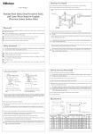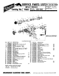
1
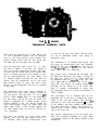
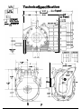
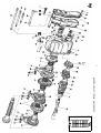
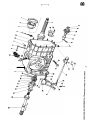
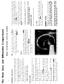
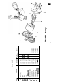
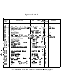
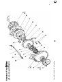
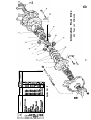
THE
SERIES
TRANSAXLE GEARBOX UNITS
These units are designed for use with 300 to 450
cu. inch competition engines, and are manufactured as two, four and five speed models. The
present manual deals with the four speed unit
(LG 500) and the five-speed unit (LG 600).
Only one final drive ratio is used (3.3 : 1). Since
the drive is indirect at all times, any change in
ratio can be made through the gearbox. The drive
is taken from the clutch shaft to the hypoid final
drive via straight cut gears. Gear change is effected by non-synchronised face dogs. Ratios can
be changed without removing the unit from the
chassis, and all requirements can be met from
OUT extensive range of gears. All ratios except
bottom are inter-changeable, and may be arranged
in any order.
The differential and crown wheel assembly is
mounted on two taper roller bearings, located in
the side plates and adjustable to correct
load by shims. Output shafts are also mounted in
the side plates, and lip oil seals are fitted. The
pinion is supported by a double angular contact
bearing clamped to the case directly behind the
gears. This bearing accepts the major radial and
thrust loads, while a roller bearing supports the
tail. Thus pinion mesh can never be affected by
case expansion.
The gears run directly on caged needle roller
bearings, and each gear and bearing revolves as
an assembly. Heat treated nickle-chrome steel
is used for all gears and shafts. Selector forks
are cast in aluminium bronze, and casings in
magnesium alloy.
The differential is of Limited Slip design, and
two types are manufactured. The unit normally
the cam and
type. The other is
supplied
type, operated by flat clutch
the
plates. Both units are illustrated.
The gearbox unit is lubricated by oil splash, and
the final drive by pump. The pump is located in
the main case, and is fed via a filter which can
be withdrawn from the
of the case. The
oil is piped out of the main case on the
hand side and returns via external piping, thus
providing for the fitting of an oil cooler. The
latter is strongly recommended to ensure that
oil temperature does not exceed its maximum of
110°C (250°F).
The gear-change rod is mounted high on the
right-hand side of the unit to facilitate the installation of the gear line linkage. The clutch
operated by steel fork and push-rod
accepted
as the simplest and most reliable system, especially with monocoque chassis. The push-rod is
actuated from a slave cylinder mounted on the
side of the main case.
The general configuration of the LG Series provides the maximum utilisation of power allied
to minimum weight for the power required to be
transmitted.
3
6, 7
.
. . . . . .
...
7
. . . . . . . . . . . . . . .
Hubs
16
6
6
12
. . . . . . . . . . . . . . .
Gearbox Unit . . . . . . . . . . . .
. . . . . .
Gear Ratios, changing
Gear Ratios, standard and special ...
Filter
End Case
6
. . . . . . . . . . . .
9
14
12, 14
6
9
12
...
...
...
. .
9, 14
6
6
9
14
PAGE
...
...
...
...
. .
. .
...
...
..
...
...
Pinion, setting up .
Differential Unit, removal . . .
Differential Unit, dismantling
Clutch Rings .
Clutch Shaft .
Crown Wheel .
Crown Wheel
Backlash,
adjusting
...
...
Bearing Carrier (Main)
...
Bearing Carrier (Clutch shaft)
B e a r i n g s
and pinion, front
and pinion, tail . . .
Index
. . . . . .
and type
. . . . . . . . .
....
9,
Technical
specification
...
...
Selector Finger
. . . . . .
Selector Forks, removal
Selector Forks, setting up . . . . . .
. . . . . . . . .
Selector Heads
Selector Rods . . . . . . . . . .
Setting up
Crown Wheel
Pinion ...
. . . . . . .
Selector Forks
.
.
.
.
. . . . .
Side Plates, removal
. . . . . .
Side Plates, dismantling
Reverse Idler Gear
. . . . . . . . .
Pinion . . .
...
Plungers
...
Pre-load, adjusting.
Oil,
Oil Pump
Oil
Filter
Main Case and Diff.
9
2
12
14
7
6, 7
6,
6
6, 7
9
14
6
14
4
10, 12
10, 12
9
PAGE
General notes on maintenance and overhaul
Only genuine
spares should be used as replacements. These are manufactured in our own workshops to the fine tolerances necessary, and rigorously
inspected and tested.
New nuts and gaskets should always be used on reassembly.
When warming the outside of the case, keep the
lamp moving. Do not overheat. Test with a spot of
moisture, which will bounce off when the case is hot
enough.
When refilling with oil, put half the quantity into each
one oil sump.
filler hole. Never put all the oil
NO.
___
Tail
Sleeve Oil Seal
Starter Sleeve
Hub First Second
Reverse
Steel Ball Selector Rod
Spring Selector Rod
Screw
Plungers
Stud
Stud
Washer
6”
Blanking Plug
Selector Finger Housing
PI unger
Spring
Plug
Bush
Alloy Spacer
Screw
..
End Cover
END Cover Rear Start
Oil Seal End Cover
Cover Starter Spline
Allen Cap Screws
Nyloc Nut
UNF
Filler Cap
Nyloc Nuts
Stud
Bearing Corrier
DESCRIPTION
T
2027
2028
203
2021
LG
LG
LG
LG
LG
LG
2261
227
228
2291
2292
H C
FT
2032
FT
2035
FT
2036
LG
20310
FT
20311
LG
204
LG 204R
LG
2041
LG4 2042
LG4 2043
LG4 2046
LG
2044
LG
2045
LG
20416
LG
20417
LGS 226
FT
FT
F
FT
FT
2013
LG
2025
LG 5 202
PART NUMBER
1
1
1
4
1
1
1
4
4
1
1
1
1
43
2
2
1
6
43
8
1
2
1
43
2
1
43
8
1
4
Not Illustrated
Not I I lustrated
Not Illustrated
Not Illustrated
Nat Illustrated
Not Illustrated
Not
Not Illustrated
Not lllustmted
5 Speed
4 Speed
5 Speed
REMARKS
NO.
Spares List A
Loyshaft Gears Other Ratios
Adjusting Spacer
Selector Finger
Gasket End Cover
Gasket Selector Finger Housing
Pinion Gears All Ratios
Layshoft Gear
Selector Fork
-
LG
LG
LG
252
260
261
1
3
1
LG5
251
-
1
1
3
1
1
1
2
1
1
!TY
LG5 250
Selector Fork
Selector Fork
LG5 249
2462
247
2341
LG 2342
LG 2343
LG 2345
LG 2346
LG5 246
LG5 234 Rs
LG4 234 Rs
FT
LG
Reverse
Rear
Front
231
2295
230
2301
2302
LG 232’
LG5 234
LG
LG
LG
LG
PART NUMBER
Nut
Selector
Selector Rod
Thrust Washer
Swcer Lovshaft
Selector Rod First
Bearing
Circlip
Clutch Ring
5 Speed
Thrust Washer
Pinion
Nut
Washer
Split Pin
Reverse
First Sliding Gear
DESCRIPTION
3
4
1
1
1
J-.
-l--
3
1
1
1
1
1
1
2
2
4
5 Speed
-4 Speed
5 Speed
4 Speed
Mode on Assemble
5 Speed
5 Speed
4 Speed
5 Speed
4 Speed
Rear Start 5 Speed
Rear Start 4 Speed
5 Speed
4 Speed
REMARKS
GEARBOX UNIT, SPARES LIST AND DIAGRAM
5
1
7
I
15
Remove the split pins from the castellated
nuts.
pinion and
be correctly paired
UNC
UNF nuts and washers,
cap screw.
RATIOS
When changing a gear ratio, take off the slackened
from the bearing carrier.
nut and remove the
one from the
Gears are exchanged in pairs
shaft and one from the pinion shaft. Each gear is
CHANGING
Replace in reverse order to above.
2. Using a plastic mallet, tap the bearing carrier
with
and remove it from the main case,
lay-shaft assembly and gear train. Support the
gears, hubs and clutch rings with the hand, as
they come off the pinion.
1. Remove the
and the
BEARING CARRIER
6
7. Take off the Selector Finger Housing by undoing
cap screw and two UNF nuts. Then
the
remove the two remaining forks.
(On the 4-speed gearbox, to remove selector
finger it is necessary to undo reverse selector
fork and push rod down until head is clear of
the others).
6. Remove
or
by sliding it into the
selector head, and pushing the rod
the head is clear of the others.
5. Remove bung, spring and plunger (13, 14, 15)
from the selector finger housing.
4. Knock back the tab and unscrew the nut from the
fork, (44). Remove the fork.
3. If forks are not to be stripped, check that nuts
are tight and properly tabbed. To continue
2. Examine forks for heavy or uneven wear, and
test for excessive play between forks and clutch
rings.
Now withdraw the two outside selector rods, to
disengage the gears.
5.
inspect for wear and cracks, giving particular
attention to the clutch rings.
1 . Remove hubs, clutch rings and gears. Wash and
STRIPPING THE GEAR TRAIN
It is essential that gears
according to these numbers.
etched with two numbers. The first is the number of
its own teeth. The second is the number of teeth on
its mating gear.
4. Remove the pinion nut and washer and slacken
off the
nut.
3. Push the heads of the two outside selector rods,
thus engaging the gears.
2.
nuts and washers
1. Remov the
from t e end cover. Take off cover and gasket.
END COVER
REMOVING THE UNIT
The Gearbox
Undo the three
cap screws (6) and take out
the top Selector Rod Springs and balls. Then
take out the three Selector Rods, followed by
the bottom balls and springs.
When replacing bottom balls and springs, set up
to correct height. About one-third of the ball
should be exposed. Continue by inserting locking
slugs and selector rods, then top balls and
springs.
Setting up the selector forks
12. Any hub renewed should be identical in length
with the original. If replacing all hubs, or main
bearing carrier, check that overall length of
pinion assembly has not been altered. Clearance
is essential to avoid overheating and seizure,
but too much clearance will cause excessive wear.
11.
Re-assemble in reverse order to above, subject to
the
tail bearings and
10. Inspect pinion
renew if necessary. To remove, warm up surrounding area.
cap screw (11) -and push
9. Undo the UNC
out the locking slugs.
8.
Then check for correct
to
Build up the hubs, gears and clutch rings, and
slide them back on to the setting jig.
5. Remove from jig. Fit selector forks to rods, with
nuts and washers.
4. Tighten the pinion
clearance on top gear.
3. Attach the bearing carrier to the jig, using temporary nuts.
2. Place the jig in a vice. Slide the hubs, with top
gear and thrust washer, on to the dummy pinion.
1 . Warm the case and drop in the pinion ta’l bearing
as described above.
Note that when two
gears run
together, their chamfered sides must face
each other. (See diagram A).
Extreme accuracy in setting up is imperative to
ensure that gears engage freely, and to avoid uneven
or excessive wear. The use of a Bewland
setting. Jig is strongly recommended. Designed
and 600 gearboxes, it will
specifically for
save costly setting-up time and vastly reduce the
possibility of error. (Fig. 1).
SETTING UP THE SELECTOR FORKS
THE GEARBOX UNIT (continued)
I.
The
fork-setting jig in
When
satisfied with the set-up, continue as
When fully engaged with either gear there
should still be clearance between the gear
and clutch-ring faces.
The clutch ring should engage fully with
either gear.
The clutch ring should be centered on its
hub, between the two gears.
Adjust the forks individually. Correct positioning
requires that:-
Fig.
Tighten up
and
selector rods.
*Correct torque is 115
and 80
for
nut.
for pinion nut,
14. As a final check, run on two or three nuts and
go through the gears. Then replace the
nuts and tighten up. Replace spacers and nuts
on pinion and layshaft, using a torque spanner.
*Put in split pins and replace end cover, using
a new gasket.
13. Put the complete set-up back into the jig. Recheck all clearances. Test all movements. When
satisfied, take it down and bolt it into the gear
box, using a jointing compound.
assembly with
12. Build up the complete
spacers and thrust washer. Replace in
bearing carrier.
11. Tighten up M/Reverse selector rod nuts. (Use
new nuts and tabs for all selector rods). At the
same time, make sure that the selector rod heads
and there is correct
are correctly aligned,
clearance between them.
selector rod. This
10. Slide back the
will enable you to replace the selector finger.
Now replace the selector finger housing, using
a new gasket.
9. Put in the
bearing, having warmed up
the surrounding area.
8.
NO.
I
Spacer Pinion Head
Pinion Bearing
Clomp
Bolt;
Tob Washers
Reverse Idler Gear
Bearing
Reverse Idler Spigot
Reverse Idler Washer
Circlip
Reverse
Retaining
Clutch Shoft Chevrolet
Clutch Shoft Ford J and B
Clutch Shoft
Clutch Shoft Oldsmobile
Blonk
Clutch
Clutch Shaft lndy Ford
Clutch Shoft
Clutch Shaft
Citclip Clutch Shaft
Circlip Clutch Shaft
Spigot Clutch Shaft
Main Case
Oil Filler Plugs
Stud Side Plote
Crown Wheel Pinion
DESCRIPTION
I
-
2252
2371
2372
2373
2374
2375
2376
239
2391
2392
2393
2394
2395
2396
LG 2390
LG 2390A
LG 244
2441
LG 2442
LG 2443
LG 2444
LG
LG
LG
LG
LG
LG
LG
LG
LG
LG
LG
LG
LG
LG
LG 2222
201
FT 2011
F T
LG 221B
PART NUMBER
-
QTY QTY
5
4
Machined
Stondord
Half
5 Speed
4 Speed
REMARKS
NO.
Spares List B
Spring
Dome
Split Pin
Oil Pump.
Screws Pump Mounting
Oil Filter
Plug
Union Complete
Clutch Fork
Fulcrum
Wosher
Swivel Bolt
Clevis Pin
Rod
Nut Adjusting
Slave Cylinder
Circlip Spigot
Oil Seol
Beoring
Screws
Thrust Bearing
Bearing Carrier
DESCRIPTION
254
24410
24411
24412
24413
24513
D G
LG 258’
F T 2581
DG
2582
2583
DG
2584
259
DG
LG
265
L G
LG
266
2661
LG
2662
LG
L G
DG
LG
LG
LG
L-G
PART NUMBER
4
1
1
4
QTY
4
Speed
REMARKS
Slacken off the top and bottom swivel pins (29)
and slide the thrust bearing and bearing carrier off
the end of the clutch shaft.
then the bearing
7. Fit a new oil seal. Replace any worn parts,
giving particular attention to the bearing.
Re-assemble in reverse order to above, and
6. Remove the large circlip
and the oil seal (22 and 21).
5. Remove small circlip and oil pump driver gear.
Remove second circlip and press clutch shaft
out of spigot housing.
cap countersunk set
4. Remove the four
screws. Slide out complete clutch shaft assembly.
3. Remove the clutch fork, after taking out the
split pin and clevis pin.
2.
1. Unhook the spring (35) from the clutch fork clevis
pin, enabling the fork to swing free.
CLUTCH SHAFT
Replace in reverse order to above.
4. Remove the right-hand side-plate.
3. Support the complete differential assembly on a
hammer shaft, and lift it out of the main case.
2. Take off the left-hand side plate, having removed
washers of plate and tie-bars.
the nuts
Loosen with light blows from a plastic mallet.
1. Take off slave cylinder (33) complete with clutch
push-rod, by removing the two bolts and washers.
DIFFERENTIAL AND DRIVE
9
Fig. 2. Easing the pinion through the side plate aperture
1. Remove the clamp plate, having first unscrewed
the five UNC bolts.
The pinion is withdrawn through one of the
plate ‘apertures by pulling it well forward into the
empty diff. compartment and tilting it. To do this, it
is first necessary to remove the bearing behind the
pinion head. Proceed as
PINION
9. When bolting the spigot to its housing, put a
cap
smear of locking fluid on the four
screws.
Check that the bearing carrier rotates
after tightening down the two swivel pins (9).
Wash and inspect all parts. Wash out main case to
remove sludge. Ensure that no small metallic objects
or particles have been left in the case.
should not be disturbed unless it has to be renewed.
The
bearing is removed by warming the
outside of the case, having first taken out the
clip. This bearing will be damaged by removal, and
BEARING
Remove the circlip that retains the driven gear.
cap screws and slide out pump
Undo the three
unit. You will now be able to lift off the gear and
woodruff key. To dismantle pump, see page! 12.
OIL PUMP
Remove the circlip and lift off the gear.
REVERSE IDLER GEAR
Replace, in reverse order to above. To fit a new
crown wheel and pinion, see page 14.
4. Tilt pinion and withdraw it through the aperture
(Fig. 2). Remove thrust washer.
3. Warm the outside of the case around the bearing,
which will now drop out provided the case is
Keep the flame moving and do not overheat.
2. Put a nut on the end of the pinion shaft for protection. Then strike with a plastic mallet and
ease the pinion forward in the empty diff. compartment.
the main case upright, with its
bolts supported on blocks.
Removal and replacement of units and assemblies
The Main Case and Differential Compartment
Pump Cover
Gear
Gear
Woodruff Key
Gear
Circlip
Geor
Allen Cap Screws
Banjo Union Complete
Adaptor J Block
Adaptor B Block
Adaptor Galaxie
Adaptor Oldsmobile
Adaptor Chevrolet
Adaptor lndy Ford
Adaptor Chevrolet
Adaptor
*
*
*
E9
El0
E5
E6
Pump Body
E2
DESCRIPTION
El
NO.
LG
LG
LG
LG
LG
LG
LG
LG
LG
LG
LG
LG
LG
LG
LG
LG
LG
LG
2078
2653
2654
2655
2656
2657
2658
2659
26510
2662
2071
2072
2073
2074
2075
2076
2077
2652
PART NUMBER
Spares List E
4
2
1
1
1
1
4
2
1
1
1
1
Speed Speed
Not
Not
Not
Not
Not
Not
Not
Not
Illustrated
Illustrated
Illustrated
Illustrated
Illustrated
Illustrated
Illustrated
Illustrated
REMARKS
10
The Oil Pump
8
E
Spares List C
QTY
DESCRIPTION
PART
Side Plate (L.H.)
Side
LG
- - - -LG
Track
DriveDriveDriveShaftShaftsShoftsDrive14004.4501400ShaftSeriesSeriesDetroitLGLGLGLG
2:
Drive Shaft 4.450 Detroit
Circlip
Drive Shaft Bolt
Nyloc Nut
Crown Wheel
Wheel
Bolts
Tab Washers
Tie
Rods
LG
Washer
Nyloc
Nut
FT
205
LG
REMARKS
1
2
2
1
2
2
1
Std
Lola C a r s
---
Std
1
a
LH1 1
RH
2
LG 2193
FT 2196
See Sheet
FT
2211
FT 2212
262
LG 2621
2196
QTY
4
1
L G 2051
LG
2053
2054
LG 206
.
2061
LG 213
LG 214
LG
215
LG 216
LG 217
2191
Plots
Outer
I n n e r Cam Track
NUMBER
a
a
10
For Alternative Drive with ‘Powr-lok’ Differential
a
a
10
See page 15
FINAL DRIVE, SPARES LIST AND DIAGRAM
with cam-and-pawl differential
Standard Final
21
11
from the
1.
shaft.
the drive shaft circlip and knock out the
Left-hand Side Plate
FINAL DRIVE
Re-assemble in reverse order to above.
Tighten with a torque spanner to
6. New bolts and tabs are used for the crown wheel
the drive shaft (11, diagram C).
5. The splines of the inner cam track are towards
4. Wash and examine for wear or damage, givin
particular attention to plungers, and profiles o
the cam tracks. Make certain
carrier.
3. Remove the eight plungers
2. Remove in turn the outer housing, outer cam track
and inner Cam’ track.
1. Bend back the tabs, remove the bolts and take
off the crown wheel.
following instructions apply to the Cam-and
type Differential in standard
and 600
Gearboxes.
alternative final drive with
Lok differential is illustrated overleaf, and clearly
shows the sequence of dismantling.
The
DIFFERENTIAL
Stripping the
above fitting
12
Snip the wire’. Unscrew the bung with an
Withdraw the filter, wash and replace.
OIL FILTER
key.
When te-assembling, make sure that the driving shaft
is nearest the flat side of the cap. (Diagram E).
This unit is extremely sturdy and simple in design.
It operates at far below its maximum rating and is
unlikely to suffer serious wear. To clean it and inspect gears and body for possible scoring, remove
cap screws and take off the pump cap.
the four
OIL PUMP
Re-assemble in reverse order
new oil seals if necessary.
Follow the same procedure as above.
Right-hand Side Plate
plate bearing and oil seal, so that both can be
withdrawn.
3. Remove the large circlip which retains the side
ing first covered the oil seals with a block of
outer track of the differmetal for
ential bearing and the shims should now drop out.
2. Support the plate on fire bricks and warm it, hav-
TO THE MAIN CASE
IMPORTANT: The bearing must be inserted with its
filler slots upwards. Clamp bolts must not be proud
clamp plate.
of
end with bell housing on the bench. Drop the adjusting spacer onto the pinion head and slide in
the pinion. Now warm up the case and drop the
bearing over the pinion and into its housing. Replace the clamp plate, using new bolts and tab
washers with a smear of locking fluid.
3. To replace the pinion, stand the casing on its
or
collapse the filter. It should be just
possible to turn the filter, using slight hand
pressure.
2. When replacing the filter bung, do not over-tighten
1. Slide the oil pump half way home, then push the
splined end of the shaft through the driven gear.
Take care to replace the woodruff key and circlip.
Slide the pump home and secure it from the back
with the three
cap screws, using a smear
of locking fluid.
Replace the units and sub-assemblies in the reverse
order to which they were dismantled, with special
attention to the
NOTES ON
Fig. 3. The
setting gauge in position
Fig. 4
How the dial recording micrometer is used to measure backlash
SETTING GUAGE
if necessary by substituting a thicker or
thinner spacer. When satisfied, remove setting
gauge. Renew clamp plate bolts and tab washers.
Assemble the differential unit and side plates
to the main case. Bolt up, including tie bars, to
normal tension.
Assemble differential unit, using the new crown
‘wheel and solid dummy bearingsin place of the
two inner differential bearings (2). The thickness
of the shims is critical. If they have to be renewed, make sure they are replaced with shims
of same thickness as the originals.
TO ADJUST THE PRE-LOAD
3.
Place a
parallel bar across the pinion, as
illustrated. Hold it flat and square with the pinion
face. Measure the clearance between the bar and
clearance is
the setting gauge (Fig.
etched on the pinion.
Assemble setting gauge to main case.
This operation is carried out with the hubs and
spacer on the pinion, and it is important that they
should be pulled up tight with the pinion nut.
USING THE
SETTING UP,
Setting up can be done in the usual way, using
faster and more positive method,
engineer’s blue.
however, is to use the new
Setting Gauge.
Procedure is as
The crown wheel and pinion are supplied as a pair,
precision matched and-lapped. Each-pair is individually tested and passed as perfect before leaving the
factory, and neither part should ever be replaced
without the other.
turn the pinion by hand to test the pre-load.
Adjust by means of shims until satisfactory.
With pinion in the setting gauge, a feeler
gauge is used to measure clearance.
14
For this operation you will require a post-mounted
dial indicator with an extended probe (Fig.
TO ADJUST THE BACKLASH
NOTE: Turn the pinion with hubs removed. Using
reasonable effort it should be possible to turn it by
gripping the splines, but more effort will be needed
with dummy bearings than with real ones. Make sure
there is some evidence of backlash. Absence of
backlash will give a false impression of pre-load.
3.
Fig.
a new Crown Wheel and
assemble one side plate to the main case. Complete the assembly of the differential and drive
unit as described above.
9. Repeat for the other side plate. After cooling,
Place a heavy weight on bearing to flatten out
shims.
8. Insert shim or shims, and outer bearing track.
retain with circlip.
7. Press the drive shaft into the side plate and
Warm up one side plate. Insert oil seal,
plate bearing and circlip.
5. Press inner bearings onto differential assembly.
RE-ASSEMBLE AS FOLLOWS:
bearings with real bearings.
4. Remove the side plates. Replace the dummy
from one side of the differential to the other.
remember that, once the pre-load has been set,
you can use only the shims that are already there.
Continue to test until satisfactory.
3. To increase or decrease backlash, change shims
through spigot
housing until it touches one of the teeth of the
crown wheel (Fig. 4). Note the reading on the
dial indicator. Turn pinion by hand to rotate
readings.
crown wheel, and take at least
readings are standard practice in our own
workshops). Minimum reading should be
2 . Insert probe of, dial
1 . Remove the solid dummy bearings from the differential unit and replace them with dummy roller
bearings. (Real bearings with increased tolerances for easy substitution).
D13
D14
D2
D3
D4
Drive
Drive
Clutch
Clutch
Tab Washer
Roll Pin
Pinion
Side
Rings Side
Metolastic
Housing
cross Shaft
DESCRIPTION
LH
SLG 2131
SLG 2 1 3 2
SLG 2 1 3 3
SLG 2 1 3 4
SLG 2 1 3 5
SLG 2 1 3 6
SLG 2 1 3 7
SLG 2 1 3 8
SLG 2 1 3 9
SLG 2 1 3 1 0
SLG 21311
SLG 2 1 3 1 2
LG 219LH
LG 219RH
Spares List D
LH
Type
PART NUMBER
1
1
2
6
1
1
1
6
4
2
1
1
4
1
10
with ‘Powr- Lok’ differential
Aiternatlve Final Drive
D