1
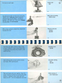
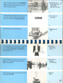
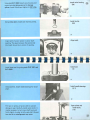
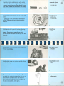
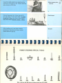
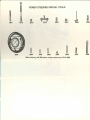
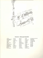
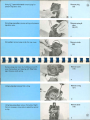
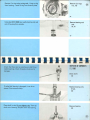
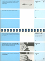
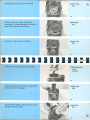
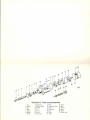
I
I
.
Produced By:
Volvo of America Corporation
NATIONAL SERVICE SCHOOL
Power I ndustrial Park
Rockleigh, N.J. 07647
For Additional Copies:
Volvo Dealership Persannel: Contact Service Representative or
Distributor Service Manager
Others:
Write address above. Cost $1.00 each prepaid . Must order 10 or more .
This book cannot be cited for warranty claims.
©Copy r ight Vo lvo of Amer ica Corporat ion , 19 73
MAINTENANCE & QUICK TESTS
Before rebuilding either power steering component, you
should always do the following:
A.
B.
Normal maintenance.
1. Check fluid level in reservoir. Fluid should be' y..
inch above full mark when engine has been brought
to normaloperating temperature and then shut off.
NOTE: Only use Type A or Dexron automatic transmission fluid.
2. Check belt tension with Kent-Moore Belt tension
gauge. New belt 100 Ibs.; Used belt 75 Ibs. Center
deflection should be 5mm (3/16 inch).
Quick Test for Proper Operation
1.
Road Test car.
Is power assist present?
a.
b. Is power assist smooth, not erratic?
Is power steering free from noise?
c.
2. Visual inspection for leaks:
a.
Check hoses and connections.
b. Check components.
3. Check front end components for damage and
alignment.
4. Check tires, rims and other related items.
5. Pressure test for proper operation. See pages IVand
V in this book. Also refer to 140 series Service
Manual, 1973 Section 6, Page 32.
Special Note: There are occasions where customers blame power steering when in fact the front-end is out or bent or, tires are soft, or
rims are damaged. Don't be fooled!
ii
TABLE OF CONTENTS
....
Do Maintenance and Quick Tests
ii
iv
Troubleshooting
v
In-Car Adjustments
vii
In-Car Pressure Testing
viii
1
Introduction to Rebuild Section
Box Disassembly (Steering Gear)
9
Box Inspection
12
Box Reassembly
Steering Gear Parts also special tools and
hand tools (Fold-out Sheet) after page 24
25
Pump Disassembly
Pump Inspection
Pump Reassembly
Pump-Parts (Fold-out Sheetl after
page 40
TROUBLESHOOTING STEERING PROBLEMS
numbers in ( ) refer to fold-out parts drawings
CARWANDERS
1. Check all steering components in QUICK TESTS.
2. Check oillevel and bleed. (Number 4 and 5 in IN-CAR
ADJUSTMENTS.)
and clean controi valve (27).
4. Rebuild or replace pump.
ENGINE STALLS AT IDLE IN LOCK POSITION
check pump and steering box. (Number 8 and 9 in IN-CAR
ADJUSTMENTS.)
PULLS TO ONE SIDE
1. Check front-end, tires, rims, brakes and frame.
2. Check all steering components in QUICK TESTS.
FRONT WHEEL SHIMMY
1. Check all steering components as in quick tests. Also check
wheel bearings.
2. Check oillevel, then bleed. (Number 4 and 5 in IN-CAR
ADJUSTMENTS.)
STEERING STIFF RIGHT AND LEFT
1. Caster out, ball joints jammed, check front end.
2. Check oil level and bleed. (Number 4 and 5 in IN-CAR
ADJUSTM ENTS.)
3. Check filter and clean channel of reservoir.
4. Check pump. (Number 8 in IN·CAR ADJUSTMENTS.)
Check and clean controi valve (27). (Number 8c in IN-CAR
AD JU STM ENTS.)
5. Rebuild or replace steering box.
SHOCKS AND JARRING IN STEERING WHEEL
1. Check oillevel, then bleed. (Number 4 and 5 in IN-CAR
ADJUSTMENTS.)
2. Adjust sector shaft pressure point. (Number 6 in IN·CAR
ADJUSTMENTS.)
3. Replace or rebuild steering box.
STEERING HEAVY ONE DIRECTlON ONLY
Rebuild or replace steering gear (the steering box).
STEERING CONTINUES TO TURN WITHOUT ASSISTANCE.
Steering valve needs adjustment (9). Rebuild or replace steering
box.
HEAVY WITH RAPID STEERING WHEEL TURNS
1. Check power steering belt.
2. Check oil, then bleed. (Number 4 and 5 in IN-CAR
ADJUSTMENTS.)
3. Check Pump. (Number 8 in IN·CAR ADJUSTMENTS.) Check
NOISE FROM PUMP
Check oillevel and bleed. (Number 4 and 5 in IN-CAR ADJUSTMENTS.)
iv
./
IN-eAR ADJUSTMENTS
numbers in ( ) refer to fold-out parts drawings
These are the only adjustments and repairs that can be done
with the unit in car. Any other corrective measures must be performed af ter removing components from vehicle.
6. ADJUST SECTOR SHAFT PRESSURE POINT. (shown in
photo 2) .
a. Jack up front end of car.
b. Remove pitman arm lock nut.
1. TIGHTEN ALL BOL TS ON STEER ING COMPONENTS.
c. Using 9992849, remove pitman arm.
2. CHECK HOSES AND REPLACE IF NECESSARY.
d. Place steering box in middle position by counting number
of turns lock to lock.
3. CHECK FLUID LEVE L AND BELT TENSION .
e. Using 17mm wrench, loosen adjusting screw lock nut.
4. CHECK OIL LEVEL, SHOULD BE 5·10mm (Y-,") ABOVE
LEVEL MARK.
f . Using 5mm allen wrench, turn adjusting screw clockwise
until slight resistance is felt when turning steering wheel
left or right of center.
5. BLEED SYSTEM.
a. Jack up front end. Check oil reservoir level. Should be
5-10mm (Y-,") ABOVE level mark.
b. Start engine. Oil level should go to level mark. Add oil if it
goes below mark.
c. Turn wheel, with engine running, lock to lock as long as air
bubbles appear in the reservoir. Add oil to keep at mark.
d. Stop engine. Oillevel should rise 5-10mm (Y-,"). If car is still
stiff or heavy rapid turns, check pump number below.
g. Tighten lock nut.
h. Check adjustment by turning steering wheel several times
from lock to lock. Slight resistance should be felt when
passing center position.
i. Set front wheels straight forward and steering wheel in
center position. Fit pitman arm and tighten nut to 17-20
kmp or 125-145 ft. Ibs.
j. Make sure alignment of pitman arm is correct.
v
7. REPlACEMENT OF CONTROl SPINDLE SEAT (54) ON
STEERING BOX. (shown in 1973 Service Manual 140 series
page 6:33 fig. 6-71, 6-72).
a. Dismantie steering shaft flange by removing two nuts and
bolts. Move steering shaft to one side.
b. Mark location of flange on spindie, remove clamping bolt
and r~move flange.
c. Remove rubber cover and circlip from shaft.
d. Carefully apply tool 9992860 to sealing ring. Tighten screw
and remove sealing ring. If ring sticks in circlip groove, carefully turn tool backwards and forwards.
e. Fill space in new seal ring lips with multipurpose grease. Fit
ring on to tool 9992863 with help of loose guide. Remove
Guide and fit ring into box.
f. Fit circlip and cover.
g. Refit flange according to marks. Distance between housing
and lower flange, 5-7mm or .20"-.28".
h. Assemble steering shaft.
i. Check oil level and bleed, number (4) above.
c. If pressure low, remove pump controi valve and clean. See
steps 76, 77, 96, 97, 98, 99, 115, 116 in this bookiet.
d. Pressure still low? Rebuild or replace pump.
9. STEERING BOX TEST FOR 140 SERIES ONlY.
a. With pressure gauge hooked up, do the pump test, number
5 above, a, b.
b. Put a 6mm (0.240") shim on each stop bolt limiting the full
steering lock. leave gauge operating valve open. Turn steering wheel to lock with force of about 100N (22 Ib) and
keep force on for 5 seconds while reading gauge. Do other
direction. If same pressures as pump test, steering gear is OK.
c. If pressure lower than pump test, check for externai leaks.
Do b. above again with 1 mm (0.040") shims. No power
steering should be present.
d. Adjust unioading valve (6) which should cancel power
steering about 3° before normal lock. Check this by test b
and c above. Only the left turn position can be adjusted. Release lock nut (5) at front of steering gear housing. Screw
out valve delays (6) the cancel of PS in makes cancel earlier.
e. Rebuild or replace box.
8. PUMP TEST - check belt condition and tension first.
a. Hook up pressure gauge SVO 2864 as shown below.
b. At engine id le, engine warm, close operating lever on pressure gauge briefly (10 seconds max). Pressure should read
67 Kp/Cm 2 (953 psi) for all modeis.
10. STEERING BOX TEST FOR 164 SERIES. Turn to lock for
5 seconds and read off pressure. If lower than pump, rebuild
or replace steering gear.
vi
In-ear Pressure Testing
(see items 8 and 9 on page vi)
164
140
test at pump
2865-2866 (5007)
unscrew
connection
box
Fi l. &-,41. POWl r , tu ring
1. Oil reurvol, Wltl> fiUer
2. Pu mp s uchon line
J . Pow., pump
., Oelivery nol line
ro. Return nil line
6. Sluring gur
vii
Install seal ring in valve housing, sealing lip
facing in. Use tool SVO 2863.
Install seal
(54)
~
Jack up car. Remove drain plug. Remove cover
from reservoir. Start and run engine for 10 sec.
Stop engine, turn wheels lock to lock until all oH
has run out. Wash component before removal.
Remove unit from vehicle and place in vise. Hold
adjusting screw with 5 mm allen wrench. Remove locknut using 17 mm box wrench.
f old-out
Refers tO
parts picture
DISASSEMBl y OF P.S. BOX.
Drain system
(6)
Put box in vise and
rem ove nut
(17)
2
Remove four bolts from top cover using
socket.
W'
Remove bolts
(19)
3
Turn adjusting screw clockwise with 5 mm allen
wrench. This will force top cover up and off. Do
not tum top cover since that will damage sealing
surface.
Remove cover by
tuming screw
(16)
4
Remove needle bearings from top cover. Also,
remove large o-ring.
Remove bearings and
o-ring.
5
Using circlip pliers, remove circlip from tension
adjusting screw. Remove screw and washer.
Remove circlip, screw
and washer.
(11, 12, 13)
6
Align sector shaft teeth in center of opening.
Using fiber hammer remove sector shaft from
housing by Iightly tapping end.
Remove sh aft
(10)
7
Use magnet on 6" handle to rem ove upper and
lower sector sh aft needle bearings.
Remove bearings
(3, 7)
8
Remove rubber cover from input shaft. With
%" box wrench remove four bolts from valve
housing.
Remove rubber cover
and bolts
(50, 51, 52)
9
Carefully rem ove valve housing. Be certain to
leave cover (30) in place as it is a ball bearing retainer.
Remove housing
(56)
10
Pull out valve assembly with cover and piston.
Do not screw assembly out.
Pull out piston and
worm.
(22,30,68)
11
Turn housing over. Remove seal retaining circlip
with circlip pliers. Remove seal using tool
SVO 2996. Take care not to damage sealing
surface.
Remove seal
(54)
12
Place piston and valve assembly in vise, splines
up. Be sure to use copper jaws. Remove caged
ball bearing.
Remove bearing.
Note: copper jaws
(59)
13
Using two medium screw drivers carefully pry up
sleeve. Do not score steering spindle or damage
roller bearing assembly under collar.
Remove sleeve
(60)
14
Remove caged needle bearings from controi
spindie.
Remove bearings
(61 )
®
15
Remove three plastic seals and three o-rings
from valve assembly.
Remove seals and
o-rings.
(62-67)
16
Screw out valve assembly. Hold cover in place
until worm gear is removed. Caution: Do not
remove torsion shaft or val ves. Complete assembly replaced if defective.
Screw out valve
assembly
(68)
17
Remove all sea I rings and o-rings from cover. Remove axial needle bearings, thrust washer, and
shims.
Disassemble cover
(32-36)
18
Using o-ring tool remove seal and o-ring from
piston.
Remove o-ring and
seal
(25,26)
19
Remove piston from vise and pour out ball bearings. Do not lose or damage any of the 23
bearings.
Remove ball bearings .
20
Drive out punch set in lock nut using punch and
4 mm chisel. Keyway must be totally clear.
Clear keyway
(27)
21
®
Using 2" spanner wrench, remove lock nut from
power piston assembly.
Remove nut
(27)
22
Slide off brass collar.
Remove collar
(24)
23
Pull out tube seal. Remove split tube by pushing
with finger from inside and prying with screwdriver.
Remove seal and
tube
(41,42)
24
Wash all components in solvent. All seal rings
and O-ring should be replaced. If you must reuse, wash in water soluble solution. Solvent
will damage seais.
INSPECTION.
Wash parts, replace
all seals
Should Be Replaced!
25
I nspect valve housing for indication of wear:
burrs, grooves, or severe scoring.
Inspect valve housing
(56)
26
Inspect gear housing for indication of wear:
burrs, grooves, or severe scoring.
Inspect housing
(4)
27
®
Check piston fit
Power piston brass cover must slide freely and
easily in housing bore and must be free of severe
scoring.
(24)
28
Check hose
connections
(56)
Check all sealing surfaces and threads for pressure and return lines.
29
A ~_
Check needle bearings. Replace if damaged. If
bearings are replaced, races must also be replaced. Remove races using tool SVD 1819.
Install using tools SVD 2995 and SVD 1801.
.
Check needle bearings
1819
30
Check parts for
damage
(22,68, 10)
Check piston, worm gear and sector sh aft for
eveness, severe scoring, sealing surface damage or
spline damage.
31
Check all threads
' (11,6,4)
Check threads and connections for damage on
gear housing, valve housing, and adjusting screw.
32
Check: caged ball bearing, caged needle bearing,
axial needle bearing, ball bearings and sleeve.
/
,, ~
.ri~--"
."
Check all bearings
(58, 60, 43, 59)
.0
@
y~
33
@
34
ASSEMBLY OF STEERING BOX.
Make certain all parts are absolutely clean.
Lightly coat parts with ATF, type A or dexron.
Replace all seals and gaskets.
Clean and oil parts;
replace seals
35
Install caged needle bearing and sleeve on control spindie. No clearance should be noted, but
sleeve should tum easily. Bearings available in
four sizes to adjust clearance.
Install bearing and
collar
(60,61 )
36
Put valve housing in vise large opening up. Place
caged ball bearing inside, seated on bearing race.
Install bearing
(59)
37
Assemble three o-rings and 3 plastic seals on
valve assembly. Install assembly in housing,
splined shaft first.
Assemble seals and
install worm gear
(68)
38
Put axial needle bearing and thrust washer on
worm .
Install bearing and
washer
(35,36)
39
Put cover on worm gear.
Install cover
(30)
40
Use appropriate bolts to hold cover to housing.
Tighten bolts to 25 ft. Ib. Adjust preload by
selecting proper thrust washer - 6 sizes are
available .. 075-.094 inch. (1.9-2.4 mm) Preload
3.7 to 6.4 Ibs. using spring gauge.
Bolt cover to housing.
Check·torque
41
When proper preload is established, disassemble
housing and cover.
Remove cover and
housing
(30, 56)
42
Assemble cover (30): 6 small o-rings; 2 large
o-rings; 1 medium o-ring; 2 small plastic seais;
1 large plastic seal; shims; thrust washer; axial
needle bearing.
Assemble cover
(28-38)
43
Coat mating surface of cover which contacts
worm gear. With marking paint.
Coat with marking
paint
(30,68)
44
Place worm gear and cover together. Check for
proper mating of surfaces by rotating with slight
pressure. If contact is poor replace seal with
larger siie .071" (1.8 mm) disassemble and clean.
Check contact, if
poor replace seal.
45
@
Assemble cover with thrust washer determined
by photo 41. Coat cover gask et with ATF. Put
cover on worm gear and bolt to valve housing
with 25 ft. Ibs. torque. Using spring gauge check
pre load 10-15Ibs. Adjust by installing additional shims. Disassemble.
Reassemble cover and
gear. Check torque.
(30, 56,68)
46
Put power piston in vise; bore to the side; ball
bearing feed hole facing up. Partially install brass
sleeve. Use copper jaws.
Put piston in vise;
copper jaws.
(22,24)
47
Insert worm gear in power piston until gear
appears in middle of first feed hole. Feed 16
balls while rotating sh af t counter clockwise.
Balls should appear in second ho le. Do not cock
worm.
Insert ball bearings
48
Put remaining 7 ball bearings in split tube using
vaseline. Put two halves of tube together and
place in gear.
Install ball bearings.
Put tube in gear
(22,42)
49
Check torque required to turn worm gear in
piston. 5-10 Ibs. using spring gauge. If reading is
incorrect replace all 23 balls. 5 sizes are available.
When reading is correct carefully disassemble
and store balls.
Check torque
50
Place o-ring and plastic sealon brass sleeve. Put
preassembled cover, locknut, and sleeve on
worm gear.
Assemble gear, cover,
nut and sleeve with
seal.
(68,30,27,24)
51
@
Put worm gear in piston and insert 23 ball bearings aeeording to previous method. Install seal
for split tube. Seat brass sleeve. Make sure all
teeth are exposed on gear.
Assemble gear and
power piston with
ball bearings.
(68,30,27,24,22)
52
Do not screw out worm gear as bearings will fall
into piston. Distanee from bottom of gear to
bottom of eover shou Id not exceed 6 inches.
WARNING
Do not screw out
worm gear
53
Seeure loeknut by setting with puneh.
Tighten lock nut
(27)
54
Put steering box in vise, positioned as it would be
in ear. Install spaeer on top of needle bearing
raee. Using tools SVD 2010 and SVD 1801. I nstall seal with lip up.
Install seal in
P.S. housing.
(8,9)
55
Install eomplete power piston, eover, and valve
assembly in P.S. housing. Teeth should be exposed in top opening.
Install piston in
housing.
(4,22,30,68)
56
Install seal ring in valve housing, sealing lip faeing
in. Use tool SVD 2863.
Install seal
(54)
57
@
Using tool SVO 2863 install valve housing over
controi spindle taking care not to damage
splines. Install 4 bolts and tighten to 25 ft.lbs.
Install valve housing
Using circlip pliers install seal retaining circlip.
Install circlip
(56)
(53)
59
Align teeth of power piston in sector shaft
opening. The space between the second and
third teeth should be in center of opening.
Align teeth
60
Installlower seal ring using tools SVO 1801 and
SVO 2995.
Install seal
(2)
61
Using vaseline, install needle bearings for sector
shaft.
Install needle bearings
(3, 7)
62
Put tape on splines of sector shaft to prevent
damage to seal. Carefully install sector shaft. It
maybe necessary to turn input shaft back and
forth slightly in order to fully seat shaft. Do not
turn too far or misalignment may occur.
Tape splines and
install shaft.
(10)
63
Assemble tension adjuster screw with washer
and circlip . Washer is available in different thicknesses to adjust clearance. There should be no
play when installed but should still turn freely.
Assemble adjuster
screw
(11,12,13)
64
I nstall needle bearings and o-ring in sector shaft
cover.
Install bearings
and o-ring.
(14, 15, 16)
CAUTION: Only sector shaft bearings can
be used. Do not exchange with other needle
bearings.
65
Install cover
(16)
Install sector sh aft cover by turning adjusting
screw counter clockwise using 5 mm allen
wrench. Do not turn cover because sealing
surfaces will be damaged and bearings may fall
into unit.
66
Bolt down cover
(19,20)
I nstall 4 bolts with washers in sector sh aft cover.
Tighten to 22 ft. Ibs.
67
Install rubber cover
(51 )
Install rubber cover over controi spindle splines
on valve housing.
68
Remove tape from sector shaft splines. Turn input shaft lock to lock to determine if % turn of
sector shaft is available either side of center.
Align marks according to figure. If neither of
the above is possible, realign gears.
d
Remove tape and
align marks.
69
f24\
Using 5 mm allen wrench turn adjusting screw
clockwise until pressure is felt. Tighten adjusting
screw locknut to 18 ft. Ibs.
Adjust pressure point ,
and lock
~
70
Using spring gauge check torque required to
turn input shaft. Torque when sh aft is in center
should be 9-13 Ibs. more than at either end of
sector shaft trave I. Maximum torque - 40 Ibs.
Check torque
71
Af ter installing unit in ear check function
according to instructions in factory service
manual section 6 page 32.
Test unit
72
POWER STEERING SPECIAL TOOLS
~
.:;
.,:.
1801
1819
2864
®
2010
~
2865
n
y
2279
c
2866
2481
a
2990
B
2995
@
2013
ij
2996
When ordering, add 999 before numbers shown here (SVO=999)
l
2860
B
2997
~
.
..;
2863
4028
-
- - - -
See over for illustration and list of
special tools and hand toois.
LIST OF SPECIAL TOOLS AND LIST OF HAND TOOLS .
SPECIAL TOOLS SVO=999
HAND TOOLS
1801 & 2010-lnner Sector Shaft
Seallnstaller
1801 & 2995-0uter Sector Shaft
Bearing Race Puller
1821-lnner Sector Shaft Bearing
Race Puller
2060-"ln Car" Power Steering
Box Seal Puller-Recommend
Dealer Purchase
2279-Power Steering Pump
Pulley Remover
2303-Drift For Removal Of
Power Steering Pump Plates
2481-Sleeve Installer
2863-Steering Box Input Shaft
Seallnstaller, Recommend
For Dealer Purchase
2864-Pressure Gauge
2865 & 2866-Gauge Adapting
Nipples (5007 For 164, 1973)
2996-Pump Housing Bearing And
Seal Installer And Remover
4028-0uter Sector Shaft Seal
Installer
5mm Allen
O-Ring Tool
2 Medium Screwdrivers
"4mm" Chisel (specially made)
Spring Gauge
Magnet On 6" Handle
Teflon Tape
Marking Paint
Vaseline
1/2" Open
7/ 8" Open
1 1/ 16" Open
17mm Open
Long Nose Pliers
Channel Lock
Circlip Pliers
Slip Joint Pliers
Copper Jaws
Automatic Trans Fluid A or Dextron
1 Vise Brass Jaws
1/2" Socket-3/ 8" Drive
Spanner
Punch
Foot Pound Torque Wrench
- -
-
.---------~-----------------------------------------------------------------------
.:.
---
POWER STEERING SPECIAL TOOLS
"---.
.·r
1801
1819
2864
®
2010
~
2865
Å
H
2481
2279
O
2866
a
2990
B
2995
@
2013
~
2996
When ordering, add 999 before numbers shown here (SVO=999)
l
2860
~
n
4028
2997
2863
"
,3~
. -
I
..
,-
; \ :
617 66 65
•
I i
6~ 6362
61
i
Illustration A. Steering gear disassembled
1.
2.
3.
4.
5.
6.
7.
8.
9.
10.
11.
12.
13.
14.
Circlip
lower seoling ring
Needle bearing
Housing
Packing
Plug
Needle bearing
Washer
Upper sealing ring
Steering shoft
Adjuster screw
Adjuster washer
Circlip
Needle bearing
15. O-ring
16. Cover
17. locknut
18. Bleeder screw
19. Balt
20. Washer
21. Plug
22. Piston
23. Pin
24 . Sleeve
25. Piston ri ng
26. O-ring
27. Ring nut
28. O-ring
29. O-ring
30. Cover
31. O-ring
32. Shims
33. O-ring
34. Packing
35. Bearing washer
36. Needle bearing
37. O-ring
38. Packing
39. O-ring
40. O-ring
41. Packing
42. Pipe halves
43. Ball
44. Balt
45. lock was her
46. Retainer
47. Washer
48. Spring
49. Washer
50. Balt
51. Rubber cover
52. Balt
53. Circlip
54. Sealing r ing
55. Washer
56_ Valve housing
57. Guide pin (only early prod.)
58. Bearing r ing
59. Ball bearing
60. Bearing sleeve
61. Needle bearing
62. Packing
63. O-ring
64. Packing
65. O-ring
66. Pocking
61. O-ring
68. Worm
Follow draining procedure and remove unit
from car. See service manual, section 6 page 31.
DlSASSEMBlY OF P.S. PUMP.
Drain and rem ove
system
73
Remove bracket and pulley from P.S. pump. Be
careful not to lose woodruff key. Use.2." box
8
wrench & puller SVO 2279.
Remove braeket &
pulley
74
Remove shaft bearing retaining circlip using
circlip pliers.
Remove circlip
(No. 5)
75
Using l T6 " open end wrench rem ove plug for
pressure regulator valve.
Remove plug
(23)
76
Using long nose pliers remove spring and pressure
regulator valve.
Remove spring &
valve
(26,27)
77
Using pliers remove large circlip for rear cover.
Remove circlip
(20)
78
Remove large rear cover by holding pump with
cover facing down and tapping with fiber hammer. Remove small spring.
Remove cover
(19)
79
Using o-ring tool remove first o-ring.
Remove o-ring
(21 )
80
Using long nose pliers remove first plate. Slight
force is necessary since plate is sealed by second
o-ring.
Remove plate
(18)
@
81
Remove o-ring
(17)
Using o-ring tool remove second o-ring.
82
Remove rotor
(25)
Using long nose pliers carefully lift rotor from
pump.
83
Remove blades
(15)
After removing rotor some blades may remain in
housing. Be certain to remove all 10.
84
Remove intermediate piece by pulling and using
slight rocking motion.
Remove plate
(16)
85
Using fiber hammer carefully tap shaft and bearing out of housing from inside.
I
Remove sh aft
(4,6)
86
Remove pump from vise; place on bench, large
opening down. Using too I SVO 2303 carefully
tap third plate down. Tool will fit thru hole in
bearing but not in plate.
Remove plate
(14)
87
,-
~--
Remove 2 o-rings using o-ring tool; 1 large o-ring
from housing; 1 small o-ring from bottom plate.
Remove 2 o-rings
(12, 13)
88
Using tool SVD 2996 tap needle bearing and seal
out of housing from outside.
Remove bearing and
seal.
(8,9)
89
Check that there are no scratches on shaft from
needle bearings. Check threads and splines for
damages.
INSPECTlON OF COMPONENTS
P.S. PUMP.
Check shaf t
(4)
90
If sealed ball bearing is damaged, it can be replaced. First remove circlip.
Replace bearing' only
if bad.
(6)
91
Place shaft in vise. Do not tighten vise. Then tap
shaft out of bearing. Replace with new bearing.
Remove bearing
(6)
92
Check needle bearing and seal. Replace if
necessary.
Check bearing and
seal
(8,9)
93
Inspect plates for wear and scoring.
Check plates
(14, 18)
94
Check rotor assembly for evidence of damage :
rotor, blades, and intermediate piece. Siades
should slide freely in rotor. Pieces are replaced
as a complete set.
Check rotor, plate
and blades
(15, 16,25)
95
Check that pressure regulator valve slides freely
in its bore.
Check valve
(27)
96
Check that valve has the same tolerance code as
housing. Number stamped on lip of housing (1
or 2) agrees with marking stamped into side of
valve (1 or 2 or II ).
Compare markings
97
If you suspect there is a problem with valve, then
disassemble it. Hold valve by side drilling. Do not
mar machined surfaces. Clean, and replace any
damaged part.
Take apart valve
if necessary.
(27)
98
Assemble valve immediately. Number of washers
regulates spring pressure and, therefore, max.
pump output.
Assemble valve
(27)
99
Thoroughly clean all parts. Replace all seais.
Clean parts
100
Make sure all parts are weil cleaned and lightly
coated with ATF. All sealing components should
be replaced.
ASSEMBly OF P.S. PUMP.
Coat parts with AT F
101
Press bearing into housing. Use tool SVD 2996.
Be certain bearing is fullV seated. Brg. should be
Install bearing.
(9)
37 mm or 1.45" from end of housing.
102
Apply grease to seal and install in housing using
tool SVD 2997.
Install seal.
(8)
103
-------
---- - -~~--~----~--l
I nstall bottom o-ring in groove in housing.
Install o-ring
(12)
104
I nstall shaft with preyiously fitted bearing into
housing by tapping with fiber hammer. Be certain bearing is fully seated. Next install brg.
retaining circlip.
Install sh aft & bearing
(4,6)
105
Place small o-ring in groove on inner plate .
Install o-ring
(13, 14)
106
Install plate over shaft in housing. Locating pin
should go in deeper indentation in plate. O-ring
faces down. Be sure plate is fully seated by
tapping with fiber hammer.
Install plate
(14)
107
Install intermediate piece with locating pin in
small hol e and arrow up.
Install plate
(16)
108
Install rotor with splines up and fine polishing
down. Insert 10 blades into rotor rounded
edges out.
Install rotor and
blades
(15,25)
109
@
Install second o-ring in groove in housing.
Install o-ring
(17)
110
I nstall last plate in housing, flange down
centering pin in larger indentation. Be certain
plate is fully sea ted and not cocked.
Install plate
(18)
111
I nstall top o-ring in groove in housing.
Install o-ring
(21 )
112
Install small spring and fit cover to housing.
Install spring and
cover.
(19,22)
113
I nstall large circlip by holding cover down with
c-clamp or hand le of hammer.
Install circlip
(20)
114
Install pressure regulator valve using care not to
damage machined surfaces.
Install valve
(27)
115
Install spring, gasket and plug. Use 11~ /I open
end wrench.
Install spring, gasket
and plug.
(23,24,26)
116
Install hose adaptor nipple, mounting braeket,
woodruff key and pu lIey.
Install nipple, braeket,
and pulley.
117
@
- -
-
13 14
12
4
Illustration B. Power pu
1.
2.
3.
4.
Nut
Wosher
Key
Shoft
5. Circlip
6. Beoring
7. Circlip
~. Seoling
ring
· Needle be .
10 Houslng
.
orlng
11.· Pin
12
g:~:~g
13:
14
g
· Inner ptote
.
mp dlsassembled
15. Blod
e
16.
Interm
17 O
. e d'late piece
. ·nng
~~.. ~uter
over
20. Circlip
21 . O·ring
plole
22. Spring
23. Plug
24. Pocking
25. Rotor
26. Spring
27. Controi vo lve
--- -
, :,:l.;,
I.
I
l'
I'
I
D
D
D
D
D
Box Inspection
Box Reassembly
Pump Disassembly
Pump Inspection
Pump Reassembly
Please send in this card when you complete a Power Steering Job .
.'
Datedone: ____~________________
Quick Tests
Troubleshooting
In-Car Adjustments
In-Car Pressure Testing
Box Disassembly
Check sections you used:
D
D
D
D
D
May we contact you?
Name
Company
Address
D Yes
Area Code
City
D No
Number
State
Zip
Zip
Circle any section above that gave you trouble or had errors.
Please Print
Phone:
ORDER BLANK
Number
Rear axle
Overdrive
Power steering
York A/C compressor rebuild
Name
Company
Address
City
Area Code
State
Do you want more books like this one?
Cost-$1.00 each. Check must come with order!
Ouantity
Please Print
Phone:
V.A.C. National Service School
Service Department
Rockleigh, New Jersey 07647
VOLVO OF AMERICA CORPORATION
Postage Will be Paid by -
Number
FIRST CLASS
PERMIT No . 25
PS
NORTHVALE,NEWJERSEY
BUSI NESS REPl y MAil
No Postage Stamp Necessary if Mailed in The U.S.
PS
Mail in your envelope to:
Fold on Line
VOLVO OF AMERICA CORPORATION
National Service School
V.A.C. Service
Rockleigh, N.J. 07647
Area
Your comments and questions are invited. If
you wish to be contacted, put your phone
number here _____________


![Lw 0 T6Ir T]Tffi - e](http://vs1.manualzilla.com/store/data/005854746_1-e09e412bc87fc94720bb0e0cc5d90107-150x150.png)