1
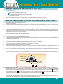
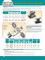
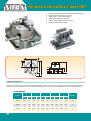
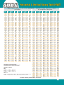
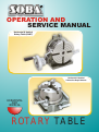
OPERATION AND
SERVICE MANUAL
Horizontal & Vertical
Rotary Table (HVRT)
Horizontal & Vertical
2 Direction Rapid Indexer
HORIZONTAL
AND
VERTICAL
ROTARY TABLE
Horizontal & Vertical Rotary Table (HVRT)
This Horizontal & vertical table is so designed as to permit machining operations at a higher dimension. The base can be used in a
vertical position to enabling to carry out center work.
Order No. & Dimensions
Table
Order No.
Height
Outer diameter
A1
D
H
Base
Width of
Bolt
dimension
T-slat
slot
Center
g
sleeve
H1
A
B
e
Type
Weight
Inch
mm
Inch
mm
Inch
mm Inch
mm
Inch
mm
Inch
mm
Inch
mm
Inch
mm
110239
2.56
65
4.33
110
3.00
76
2.83
72
5.67
144
5.12
130
0.47
12
0.75
19
110242
3.00
76
5.91
150
3.03
77
3.94
100
7.87
200
6.30
160
0.39
10
0.59
110243
3.94
100
7.87
200
4.13
105
5.31
135
10.43
265
8.66
220
0.47
12
110244
4.33
110
9.84
250
4.53
115
6.50
165
12.80
325
11.02
280
0.47
110245
5.32
130
11.81
300
5.32
135
7.68
195
15.27
388
12.99
330
0.55
Kg/lb
Worm
Gear
ratio
Kg
lb
MT-2
7
18.7
90:1
15
MT-2
12 26.4
90:1
0.67
17
MT-3
26 57.2
90:1
12
0.67
17
MT-3
48 105.8
90:1
14
0.71
18
MT-4
74 162.8
90:1
10
11
12
01
09
03
02
13
14
15
05
09
04
08
07
FREE POSITION
06
Part No. Parts Names
HVRT - 01
Main body
HVRT - 02
Table
HVRT - 03
Worm wheel
HVRT - 04
Worm Metal
HVRT - 05
Metal setting Screw
HVRT - 06
HVRT - 07
HVRT - 08
HVRT - 09
ALIGN WITH
X-Y- CO, ORDINATES
OF MACHINE TO
CENTRALIZE
IF GRUB SCREW
LOOSE THEN LOCK
ROD CAN BE
MOVED
IF GRUB SCREW
LOOSE THEN LOCK
ROD CAN BE MOVE
LOCK POSITION
UN LOCK POSITION
1
Vernier Ring
Micro Collar
Hand wheel
Clamp piece
Horizontal & Vertical Rotary Table (HVRT)
OPERATING INSTRUCTION AND FUNCTION OF EACH UNIT
1.
2.
3.
The worm gear is 1: 90.
One turn of the handle moves the table by 4"
Micro - collar is graduated in steps of 1 min.
Vernier scale makes settings down to 10 seconds possible
(20 seconds for 110242)
Dividing of 2 to 100 can be carried out quickly and accurately by attaching a Dividing Mechanism.
Center work can also be carried out by using the base in the vertical Position in conjunction with a tailstock.
THERE ARE THREE METHODS OF SETTING POSITIONS USING A ROTARY TABLE
1.
a
Use the degree scale on the outer edge of the table
(scale reading = 1 degree)
To use the degree scale on the table top, disengage the worm by unlocking the T screw and rotating the pin on the worm collar clockwise.
The table can be rotated by hand and can be locked in any position using the lock clamps.
2.
a
Use the degree handwheel (scale on handwheel = degrees and minutes)
To use the handwheel, unlock or loosen the T screw and rotate the pin on the worm collar anti-clockwise and when the worm has
engaged, lock or tighten the T screw. If the worm collar will not rotate easily, it may be necessary to rotate the handwheel while keeping
pressure on the pin so the worm will mesh or engage.
The hand wheel is divided into degrees and minutes eg: 4 degrees per revolution or ratio of 90:1. The minute divisions on the handwheel
can be further divided into 20 seconds using the vernier scale.
3.
a
Use the index method (use index plates and refer index table)
To use the index method first refer to the index table to select the index plate with the correct holes on the circle. (See Index table located
on the Page-6 back of this manual)
To use the index plates, the hand wheel must be removed by loosening the centre retaining screw and washer.
Mount the appropriate index plate with the correct number of holes to the collar with 3 screws.
Next fit the sector arms (the brass pieces) and adjust the sector arms for the correct number of holes. Holes are counted after the pin or
first hole. So for six holes, sector arms are actually set for seven holes ie; pin + 6 holes.
Fit the retaining washer in the groove in front of the sector arms.
Fit the crank with the spring loaded handle, adjusting so the plunger lines up with the correct circle of holes. Tighten with the screw and
washer that held the handwheel.
To index, rotate the handle the correct number of full turns anf then using the sector arms to measuer the number of holes. After the
handle is locked in, rotate the arms ready for the next cycle or index.
b
c
d
e
f
g
Eg: For 21 tooth gear or 21 divisions, Use the 21 hole plate. Set the sector arms for 6 holes then rotate the handle 4 full turns plus 6 holes.
If in doubt, have a practice run
WORM SHAFT
SCREW A
MAIN BODY
WORM METAL
STEEL BALL
SCREW B
SHOWING SECTION
A
B
1. Adjusting Mesh of worm Gear:- Loosen the metal clamp handle and turn the switch metal clockwise until it touches the stopper. The
worm gear has now been disengaged. Turn it counterclockwise until it touches the stopper, the worm and gear wheel will engage.
Tighten the metal clamp handle after engagement. An additional adjustment can be obtained by removing the screw A and steel ball
and turning the inner screw B counter clock-wise so bringing the worm in closer engagement with the gear wheel. Turning clock-wise
brings the worm away from the wheel. After adjustment insert the steel ball and tighten screw A
2. Axial Adjustment of Worm shaft:- When axial slack occurs gear adjustment is carried out by tightening the inside worm shaft nut after
the handle, vernier ring and switch metal have been removed. After adjustment, lock the nut on the shaft by means of the set screw. (The
ROTARY TABLE has an adjustment, nut, which can be used after removal of the handle.)
2
Horizontal & Vertical Rotary Table (HVRT)
SPECIAL ACCESSORIES
TAIL STOCK
The height can be varied when working with different index centers, while the angle of inclination can be changed for various machining
applications. In addition, the tip of the center is finely rotatable. Clamping is made by tighting of bolts
Order No. & Dimensions for Tail Stock Unit mm/in.
Center Height
Order No.R
Maximum
Suitable for
Minimum
Inch
mm
Inch
mm
111301
3.94
100
3.15
80
110247
6.53
200
4.05
135
110248
8.26
210
6.29
160
110245
111304
3.27
83
2.20
56
111300, 110240,
111305, 111310
110275
110239, 110242,
110280, 110285
110243
110244
111301
DIVIDING MECHANISM
111304
01-B
• Indexing plates sets
• (A plate, B plate
and C plate) each 1
• Sector 1
• Crank handle 1
• Sector spring 1
05
DIVIDING MECHANISM & INDEXING PLATES
Indexing Plates
02
03
01-A
Simple indexing consists of a series of preset holes in a
backing plate, these divisions are provided for the most
common angles (such as 90°, 45° and 30°). The
remaining divisions of a circle are provided by manually
rotating the dividing arm using index plates. Tables or
calculations are required to use this method.
04
01-C
Order No. & Dimensions
Major dimension of DM
Order No.
Dividing plate
set screw
110260
32
PCD.
1.26Ø
Inner diameter
of sector arm
Outer diameter
of spring clip
Grove width
Weight
Shipping
Measurement
in handle plate
ft
Inch
mm
Inch
mm
Inch
mm
0.83
21
0.71
18
0.03
Plates
Kg
lb
9
2.5
5.51
0.12
3
110265
(3holes) 46
PCD.
1.81
1.12
28.7
1.73
44
0.39
10
4
8.82
0.12
2
110270
(3holes) 46
PCD.
1.81
1.12
28.7
1.73
44
0.39
10
4
8.82
0.12
2
SOME POSSIBLE USES OF A ROTARY TABLE
Cutting gears
Machining hex or square on a shaft
Drilling holes equal distance around a circle eg holes in a flywheel
Used as an adjustable angle plate - eg machine one face then rotate 90° degrees and machine the next face
Milling a radius or an arc
Create wheels with spokes by using the rotary table to machine out the triangular shaped holes in a wheel
3
Indexing
Horizontal & Vertical Rotary Table (HVRT)
IN CASE OF AN OPTIONAL DM DEVICE ATTACHED
Indexing of 2 to 100 can be made accurately and quickly.
Equation of Indexing
Since the worm ratio is 1 : 90, when the handle is made to rotate a 360° revolution, the table therefore will rotate a 1/90 revolution. The
relationships between handle revolution 'N' and dividual number 'T" to be sought are shown in the following equation:
N=
90
T
Remarks: The index table on Page-6 is made on the basis of this
equation.
(Example)
In case where the operator wants to index the position divided into
29 equal parts. Hints on operation As for 29 dividual numbers, the
number of crank handle revolutions (N) is 9/87 as shown in the table on
Page-6 so that the handle should be rotated a full 360° revolution three
times plus an interval of nine holes. (in this time, it means hole intervals
not hole numbers). After setting this point as a start point, rotate the
handle a full 360° revolution three times plus an interval of nine holes.
When the procedure is repeated in turn as many as 29 times, the
indexing of dividing into 29 equal parts is thus achieved.
Worm Sharft
Sector
Worm Wheel
Crank Handle
OPERATIONS OF CRANK HANDLE AND SECTOR
In case of Example 'Division into 29 Equal Parts' aforesaid, it is natural that indexing operation should proceed with the intervals of nine
holes after setting the index plate (B plate) on which a row of 87 holes are provided. But in this method, the operator has to count nine holes'
intervals one by one. He must feel inefficient. In this viewpoint, it is necessary to use a device called 'sector' to avoid such troublesome
procedures. The following will describe some necessary procedures for operation of the sector.
a. Loosen the crank handle lock nut, adjust its length so as to cause the index, pin to fall in the
train of 87 holes, and retighten it.
b. Loosen the set-screws of the sector, open two arms in accordance with the interval of nine
holes (total numbers of holes are ten), and retighten with set-screws.
c. First, bring the left arm of the sector near to the index pin's left side.
d. Next, rotate the crank handle clock-wise to apply it to the right arm of the sector so that the
index pin will fall in the hole located at this right arm's left side surface.
e. Rotate the sector clockwise this time, and put the right side surface of the life arm to the
side surface of the left arm to the left side of the index pin. In this time, the relationships
between the index pin and the sector's left arm in their positions are the same as in Par. c).
The index plate hole that actually accommodates the index pin is located at the point where
goes across ten holes to the right away from the hole as in Par. c)
f. Repeat the same procedures as necessary.
Crank Handle
Index Pin
OPERATORS RESPONSIBILITY:Please take the time to read the users instructions.
Descriptive notations in our catalogue and discussions with staff are offered as a guide only. Purchasers must satisfy themselves as to
(a) The suitability of the product for their particular application and
(b) The process by which the product is used.
4
Horizontal & Vertical Rotary Table (HVRT)
1.
2.
3.
4.
5.
6.
3 Jaw chuck fitted Head The big range clamping capacity.
Dividual number 24-notch (15° each)
Table scale 1°, for angular indexing
Horizontal / Vertical & 2 direction
Suit for milling & drilling machine using
Optional: Tailstock Nr 110240
111301
C
14
D
B
E
A
20
62
14
14
14
41
CHARACTERISTIC
Useful for 2 Direction horizontal & Vertical milling and drilling operations. It has a 3 Jaw chuck fitted on the head for big range clamping.
The indexer has a simple rapid operation with Dividual number 24 - notch (15° each) and a Table scale of 1° for angular indexing.
RAPID INDEXER
A
B
C
D
E
Weight Kg.
Order Nr.
5
Inch
mm
Inch
mm
Inch
mm
Inch
mm
Inch
mm
110275
6-3/8
160
4-3/4
120
4-3/4
120
2-3/16
55
5
120
6.3
110280
7-3/8
185
5-3/4
145
5-3/4
145
2-5/8
66
5-3/8
135
9.3
110285
8
200
6-3/8
160
6-3/8
160
3-3/16
80
6-3/16
155
14
Horizontal & Vertical Rotary Table (HVRT)
INDEX TABLES FOR 6",8",10" & 12" HORIZONTAL / VERTICAL ROTARY TABLE 90:1 RATIO
DP - 2 for HV-8 DP - 3 for HV-10, 12
DP - 1 for HV-6
Number
Plate and
Circle
Complete
Turns
1
ANY
90
51
2
ANY
45
52
3
ANY
30
4
A20
22
5
ANY
6
ANY
7
B21
12
8
A20
11
9
ANY
10
59
N/A
10
ANY
9
60
A20
Part of
Turn
Number
Plate and
Circle
Number
Plate and
Circle
Complete
Turns
N/A
2
ANY
45
N/A
3
ANY
30
Complete
Turns
Part of
Turn
Part of
Turn
Plate and
Circle
Complete
Turns
48
A32
1
28/32
49
A49
1
41/49
Number
Part of
Turn
53
N/A
4
A26
22
13/26
50
A30
1
24/30
54
A18
1
12/18
4
A28
22
14/28
51
A34
1
26/34
18
55
B33
1
21/33
5
ANY
18
52
A26
1
19/26
15
56
N/A
6
ANY
15
53
A53
1
37/53
18/21
57
A19
1
11/19
7
A28
12
24/28
54
A30
1
20/30
5/20
58
B29
1
16/29
7
B77
12
66/77
54
B63
1
42/63
8
A28
11
7/28
55
A44
1
28/44
1
10/20
8
A44
11
11/44
55
B77
1
49/77
9
ANY
10
56
A28
1
17/28
10
ANY
9
57
A38
1
22/38
11
A44
8
8/44
58
B87
1
48/87
11
B77
8
14/77
59
A59
1
31/59
10/20
11
B33
8
6/33
61
N/A
12
A20
7
10/20
62
B31
1
14/31
13
C39
6
36/39
63
B21
1
9/21
14
B21
6
9/21
64
N/A
15
ANY
6
65
C39
1
15/39
12
A26
7
13/26
60
A34
1
17/34
16
A16
5
10/16
66
B33
1
12/33
12
A28
7
14/28
60
A32
1
16/32
17
A17
5
5/17
67
N/A
13
A26
6
24/26
61
B61
1
29/61
18
ANY
5
68
N/A
13
B91
6
84/91
62
B93
1
42/93
19
A19
4
14/19
69
B23
1
7/23
14
A28
6
12/28
63
A49
1
21/49
20
A20
4
10/20
70
B21
1
6/21
14
B77
6
33/77
63
B77
1
33/77
21
B21
4
6/21
71
N/A
15
ANY
6
64
A32
1
13/32
22
B33
4
3/33
72
A20
1
5/20
16
A32
5
20/32
65
A26
1
10/26
23
B23
3
21/23
73
N/A
17
A34
5
10/34
65
B91
1
35/91
24
A20
3
15/20
74
C37
1
8/37
18
ANY
5
66
A44
1
16/44
25
A20
3
12/20
75
A20
1
4/20
19
A38
4
28/38
66
B99
1
36/99
26
C39
3
18/39
76
N/A
20
A26
4
13/26
67
B67
1
23/67
27
A18
3
6/18
77
N/A
20
A28
4
14/28
68
A34
1
11/34
28
N/A
78
C39
21
A28
4
8/28
69
A46
1
14/46
21/69
29
B29
3
30
ANY
3
31
B31
2
32
A16
33
B33
34
1
6/39
79
N/A
21
B77
4
22/77
69
B69
1
80
A16
1
2/16
22
A44
4
4/44
70
A28
1
8/28
28/31
81
A18
1
2/18
22
B77
4
7/77
70
B63
1
18/63
2
13/16
82
C41
1
4/41
23
A46
3
42/46
71
B71
1
19/71
2
24/33
83
N/A
23
B69
3
63/69
72
A32
1
8/32
A17
2
11/17
84
N/A
24
A28
3
21/28
72
A44
1
11/44
35
B21
2
12/21
85
N/A
24
B44
3
33/44
73
B73
1
17/73
36
A20
2
10/20
86
C43
1
2/43
25
A30
3
18/30
74
A37
1
8/37
37
C37
2
16/37
87
B29
1
1/29
26
A26
3
12/26
75
A30
1
6/30
38
A19
2
7/19
88
N/A
26
B91
3
42/91
76
A38
1
7/38
39
C39
2
12/39
89
N/A
27
A30
3
10/30
77
B77
1
13/77
40
A20
2
5/20
90
ANY
27
B63
3
21/63
78
A39
1
6/39
41
C41
2
8/41
91
N/A
28
A28
3
6/28
78
B91
1
14/91
42
B21
2
3/21
92
N/A
29
B87
3
9/87
79
B79
1
11/79
43
C43
2
4/43
93
B31
30/31
30
ANY
3
80
A32
1
4/32
44
N/A
94
C47
45/47
31
B93
2
84/93
81
B63
1
7/63
45
ANY
2
95
A19
18/19
32
A32
2
26/32
81
B81
1
9/81
46
B23
1
22/23
96
A16
15/16
33
B99
2
72/99
82
A41
1
4/41
47
C47
1
43/47
97
N/A
34
A34
2
22/34
83
B83
1
7/83
48
A16
1
14/16
98
C49
45/49
35
A28
2
16/28
84
A28
1
2/28
49
C49
1
41/49
99
B33
30/33
35
B63
2
36/63
85
A34
1
2/34
50
A20
1
16/20
100
A20
18/20
36
A26
2
13/26
86
A43
1
2/43
36
A28
2
14/28
87
B87
1
3/87
37
A37
2
16/37
88
A44
1
1/44
38
A38
2
14/38
89
B89
1
1/89
39
A26
2
8/26
90
ANY
1
39
B91
2
28/91
91
B91
90/91
40
A28
2
7/28
92
A46
45/46
3/29
Description of In the index table.
This table is the one being calculated for the
index plate with hole number shown below.
NUMBER OF HOLES
40
A44
2
11/44
93
B93
90/93
DP-1
A Plate.....15, 16, 17, 18, 19, 20
B Plate.....21, 23, 27, 29, 31, 33
C Plate.....37, 39, 41, 43, 47, 49
41
A41
2
8/41
94
A47
45/47
42
A28
2
4/28
95
A38
36/38
42
B63
2
9/63
96
A32
30/32
43
A43
2
4/43
97
B97
90/97
DP-2 & 3
A Plate.....26, 28, 30, 32, 34, 37, 38, 39, 41, 43, 44, 46, 47, 49, 51, 53, 57, 59
B Plate.....61, 63, 67, 69, 71, 73, 77, 79, 81, 83, 87, 89, 91, 93, 97, 99
44
A44
2
2/44
98
A49
45/49
45
ANY
2
46
A46
1
46
B69
47
A47
99
A44
40/44
44/46
99
B99
90/99
1
66/69
100
A30
27/30
1
43/47
For index numbers greater then 10, use formula
6
Machine Tool Accessories
Horizontal / Vertical Rotary Tables
Precision Machine Vises
• Vises
• Engineering &
Cutting Tools
• Drill Sleeves & Sockets
• Boring Heads &
Tool Holders
• Tool Bits, Reamers &
Endmills
• Measuring Tools
• Plate Shears
• Punches & Chisels
• Woodworking Tools
• Boring Bars
• Micro Boring Tools
• Endmills
• Turning Tools
• E-Boring Bars