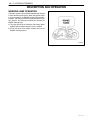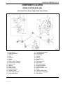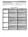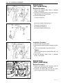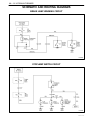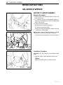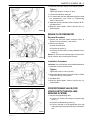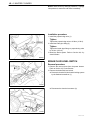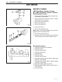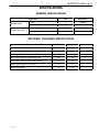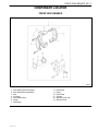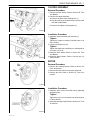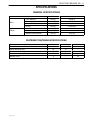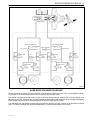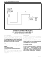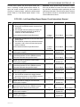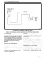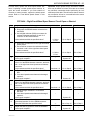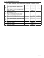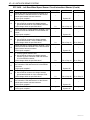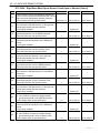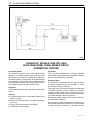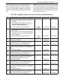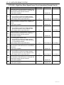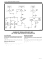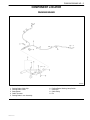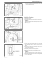
1
SECTION 4A
HYDRAULIC BRAKES
CAUTION: Disconnect the negative battery cable before removing or installing any electrical unit or when a
tool or equipment could easily come in contact with exposed electrical terminals. Disconnecting this cable
will help prevent personal injury and damage to the vehicle. The ignition must also be in B unless otherwise
noted.
TABLE OF CONTENTS
Description and Operation . . . . . . . . . . . . . . . . . .
Warning Lamp Operation . . . . . . . . . . . . . . . . . . .
Component Locator . . . . . . . . . . . . . . . . . . . . . . . .
Brake System (Non-ABS) . . . . . . . . . . . . . . . . . .
4A-2
4A-2
4A-3
4A-3
Repair Instructions . . . . . . . . . . . . . . . . . . . . . . . . .
On-Vehicle Service . . . . . . . . . . . . . . . . . . . . . . . . . .
Brake Hose (Front) . . . . . . . . . . . . . . . . . . . . . . . .
Brake Hose (Rear) . . . . . . . . . . . . . . . . . . . . . . . .
Diagnostic Information and Procedures . . . . .
Brake System Testing . . . . . . . . . . . . . . . . . . . . . .
Brake Hose Inspection . . . . . . . . . . . . . . . . . . . . .
Warning Lamp Operation . . . . . . . . . . . . . . . . . . .
4A-4
4A-4
4A-4
4A-5
Stoplamp Switch . . . . . . . . . . . . . . . . . . . . . . . . . . 4A-9
Brake Pedal . . . . . . . . . . . . . . . . . . . . . . . . . . . . . 4A-10
Specifications . . . . . . . . . . . . . . . . . . . . . . . . . . . . 4A-13
General Specifications . . . . . . . . . . . . . . . . . . . . 4A-13
Brake System Fault . . . . . . . . . . . . . . . . . . . . . . . . 4A-5
Manual Bleeding the Brakes . . . . . . . . . . . . . . . . 4A-6
Pedal Travel Check . . . . . . . . . . . . . . . . . . . . . . . . 4A-6
Fastener Tightening Specifications . . . . . . . . . . 4A-13
Schematic and Routing Diagrams . . . . . . . . . . 4A-14
Brake Lamp Warning Circuit . . . . . . . . . . . . . . . 4A-14
Brake Pedal Free Play Inspection . . . . . . . . . . . 4A-7
Stoplamp Switch Circuit . . . . . . . . . . . . . . . . . . . 4A-14
DAEWOO M-150 BL2
4A-8
4A-8
4A-8
4A-9
4A – 2 HYDRAULIC BRAKES
DESCRIPTION AND OPERATION
WARNING LAMP OPERATION
This brake system uses a BRAKE warning lamp located
in the instrument panel cluster. When the ignition switch
is in the III position, the BRAKE warning lamp should illuminate. It should go off when the ignition switch return
to II position. The following conditions will activate the
BRAKE warning lamp.
D The lamp should be on whenever the parking brake
applied and the ignition switch is in the II position.
D A low fluid level in the master cylinder will turn the
BRAKE warning lamp on.
D17A007A
DAEWOO M-150 BL2
HYDRAULIC BRAKES 4A – 3
COMPONENT LOCATOR
BRAKE SYSTEM (NON–ABS)
(Left–Hand Drive Shown, Right–Hand Drive Similar)
MAB4A001
1.
2.
3.
4.
5.
6.
7.
8.
9.
10.
11.
12.
13.
14.
15.
16.
17.
Power Booster
Power Booster Boot
Cotter Pin
Clevis
Clevis Pin
Packing
Spacer
Master Cylinder Assembly
Fluid Reservoir Assembly
Reservoir Cap
Reservoir
Grommet Seal
Master Cylinder
Proportioning Valve
Stoplamp Switch
Brake Pedal Assembly
Clutch Pedal Spring
DAEWOO M-150 BL2
18.
19.
20.
21.
22.
23.
24.
25.
26.
27.
28.
29.
30.
31.
32.
33.
34.
Pedal Bracket Assembly
Clutch Pedal Pad
Clutch Pedal
Cushion
Bushing
Retaining Ring
Spring
Brake Pedal Pad
Brake Pedal
Brake Pedal Spring
Accelator Pedal Pad
Accelator Pedal
Rear Drum Brake Hose
E Ring
Front Disc Brake Hose
Brake Hose Coupling Bolt
Plain Washer
4A – 4 HYDRAULIC BRAKES
DIAGNOSITIC INFORMATION AND PROCEDURES
BRAKE SYSTEM TESTING
(Left–Hand Drive Shown, Right–Hand
Drive Similar)
Brakes should be tested on a dry, clean, reasonably
smooth and level roadway. A true test of brake performance cannot be made if the roadway is wet, greasy, or
covered with loose dirt whereby all tires do not grip the
road equally. Testing will also be adversely affected if the
roadway is crowned so as to throw the weight so roughly
that the wheels tend to bounce.
Test the brakes at different vehicle speeds with both light
and heavy pedal pressure; however, avoid locking the
brakes and sliding the tires. Locked brakes and sliding
tires do not indicate brake efficiency since heavily
braked, but turning, wheels will stop the vehicle in less
distance than locked brakes. More tire-to-road friction is
present with a heavily braked, turning tire than with a
sliding tire.
Because of the high deceleration capability, a firmer
pedal may be felt at higher deceleration levels.
There are three major external conditions that affect
brake performance:
D Tires having unequal contact and grip of the road will
cause unequal braking. Tires must be equally inflated, and the tread pattern of the right and the left
tires must be approximately equal.
D Unequal loading of the vehicle can affect the brake
performance since the most heavily loaded wheels
require more braking power, and thus more braking
effort, than the others.
D Misalignment of the wheels, particularly conditions of
excessive camber and caster, will cause the brakes
to pull to one side.
To check for brake fluid leaks, hold constant foot pressure on the pedal with the engine running at idle and the
shift lever in NEUTRAL. If the pedal gradually falls away
with the constant pressure, the hydraulic system may be
leaking. Perform a visual check to confirm any suspected leaks.
Check the master cylinder fluid level. While a slight drop
in the reservoir level results from normal lining wear, an
abnormally low level indicates a leak in the system. The
hydraulic system may be leaking either internally or externally. Refer to the procedure below to check the master cylinder. Also, the system may appear to pass this
test while still having a slight leak. If the fluid level is normal, check the vacuum booster pushrod length. If an incorrect pushrod length is found, adjust or replace the
rod.
Check the master cylinder using the following procedure:
D Check for a cracked master cylinder casting or brake
fluid leaking around the master cylinder. Leaks are indicated only if there is at least one drop of fluid. A
damp condition is not abnormal.
D Check for a binding pedal linkage and for an incorrect
pushrod length. If both of these parts are in satisfactory condition, disassemble the master cylinder and
check for an elongated or swollen primary cylinder or
piston seals. If swollen seals are found, substandard
or contaminated brake fluid should be suspected. If
contaminated brake fluid is found, all the components
should be disassembled and cleaned, and all the rubber components should be replaced. All of the pipes
must also be flushed.
Improper brake fluid, or mineral oil or water in the fluid,
may cause the brake fluid to boil or cause deterioration
of the rubber components. If the primary piston cups in
the master cylinder are swollen, then the rubber parts
have deteriorated. This deterioration may also be evidenced by swollen wheel cylinder piston seals on the
drum brake wheels.
If rubber deterioration is evident, disassemble all the hydraulic parts and wash the parts with alcohol. Dry these
parts with compressed air before reassembly to keep alcohol out of the system. Replace all the rubber parts in
the system, including the hoses. Also, when working on
the brake mechanisms, check for fluid on the linings. If
excessive fluid is found, replace the linings.
If the master cylinder piston seals are in satisfactory
condition, check for leaks or excessive heat conditions.
If these conditions are not found, drain the fluid, flush the
master cylinder with brake fluid, refill the master cylinder, and bleed the system. Refer to “Manual Bleeding
the Brakes” in this section.
BRAKE HOSE INSPECTION
The hydraulic brake hoses should be inspected at least
twice a year. The brake hose assembly should be
checked for road hazard damage, cracks, chafing of the
outer cover, and for leaks or blisters. Inspect the hoses
for proper routing and mounting. A brake hose that rubs
on a suspension component will wear and eventually
fail. A light and a mirror may be needed for an adequate
inspection. If any of the above conditions are observed
on the brake hose, adjust or replace the hose as necessary.
DAEWOO M-150 BL2
HYDRAULIC BRAKES 4A – 5
WARNING LAMP OPERATION
This brake system uses a BRAKE warning lamp located
in the instrument panel cluster. When the ignition switch
is in the III position, the BRAKE warning lamp should
glow and then go OFF when the ignition switch returns
to the II position.
The following conditions will activate the BRAKE lamp:
D Parking brake applied. The light should be on whenever the parking brake is applied and the ignition
switch is II.
D Low fluid level. A low fluid level in the master cylinder
will turn the BRAKE lamp ON.
BRAKE SYSTEM FAULT
ÁÁÁÁÁÁÁÁÁÁ
ÁÁÁÁÁÁÁÁÁÁÁÁÁ
ÁÁÁÁÁÁÁÁÁÁÁÁÁÁ
ÁÁÁÁÁÁÁÁÁÁ
ÁÁÁÁÁÁÁÁÁÁÁÁÁ
ÁÁÁÁÁÁÁÁÁÁÁÁÁÁ
Condition
Brake Warning Lamp ON
Stoplamp ON
Poor Braking
Dragging Brake
Pedal Over Stroke
DAEWOO M-150 BL2
Probable cause
Correction
D Brake fluid leaks.
D Repair the leaks or add th fluid.
D Parking brake switch shorted to
ground.
D Repair the short ground.
D Faulty the fluid level sensor.
D Replace the sensor.
D Faulty the stoplamp switch.
D Replace the stoplamp switch.
D Push rod length is short.
D Adjust the push rod length of the
power booster.
D Stoplamp switch circuit shorted to
battery.
D Repair or Replace the wiring harness.
D Brake fluid lacks or leaks.
D Repair the leaks or add the fluid.
D Brake fluid contamination.
D Replace the fluid.
D Air in the brake system.
D Bleed the brake system.
D Damaged brake lines.
D Replace the brake lines.
D Damaged vacuum hose or faulty
check valve.
D Replace the vacuum hose or check
value.
D No free play at the brake pedal.
D Adjust the free play.
D Weakened the brake pedal return
spring.
D Replace the return spring.
D Faulty master cylinder.
D Replace the master cylinder.
D Air in the brake system.
D Bleed the brake system.
D Brake fluid lacks or leaks.
D Repair the leaks or add the fluid.
D Poor adjustment of the brake pedal
free play.
D Adjust the push rod length of the
power booster.
4A – 6 HYDRAULIC BRAKES
MANUAL BLEEDING THE BRAKES
Important: The bleeding sequence is as follows; right
rear, left rear, right front, and left front.
Important: Check the fluid level and add the fluid during
the bleeding operation.
1. Raise the vehicle.
2. Remove the bleeder screw and cap.
5. Tighten the bleeder screw after loosening the bleeder
screw and draining the fluid.
Caution: Hold the brake pedal until tightening the
bleeder screw.
6. Repeat the step 5, 6 until all the air is removed.
7. Check the leaks for the bleeder screw.
PEDAL TRAVEL CHECK
1. Start the engine.
2. Push the pedal three times.
3. With brake pedal depressed with a about 30Kg (66.15
lb) load, measure the clearance between the pedal
pad and the lower dash panel.
Unit : mm (in.)
ÁÁÁÁÁÁÁÁÁ
ÁÁÁÁÁÁÁÁÁ
ÁÁÁÁÁÁÁÁÁ
ÁÁÁÁÁÁÁÁÁ
ÁÁÁÁÁÁÁÁÁ
ÁÁÁÁÁÁÁÁÁ
Specification
60 (2.36)
D17B703B
3. Attach a transparent tube over the valve. Allow the
tube to hang submerged in brake fluid in a transparent container.
D107A304
4. If clearance is less than 60mm (2.36 in.), the most
possible cause is either rear drum brake shoes are
worn out beyond the specification value or air is in
lines. Clearance still remains less than 60mm (2.36
in.) even after replacement of brake shoes and bleeding of the brake system, other possible but infrequent
cause is malfunction of rear drum brake shoe adjusters or booster push rod length out of adjustment.
5. Automatic clearance adjuster check is performed after removing brake drums. If the faulty is found, repair
or replace it.
D107A303
4. Slowly push the brake pedal several times and hold
the brake pedal.
DAEWOO M-150 BL2
HYDRAULIC BRAKES 4A – 7
3. Brake pedal free play can not be adjusted.
BRAKE PEDAL FREE PLAY
INSPECTION
1. Push the brake pedal several times to discharge the
vacuum of the power booster.
2. Measure the pedal movement until the hardness is
felt when pushing the brake pedal by hand.
ÁÁÁÁÁÁÁÁÁ
ÁÁÁÁÁÁÁÁÁ
ÁÁÁÁÁÁÁÁÁ
ÁÁÁÁÁÁÁÁÁ
ÁÁÁÁÁÁÁÁÁ
ÁÁÁÁÁÁÁÁÁ
Unit : mm (in.)
Specification
6–10 (0.24–0.31)
D107A305
DAEWOO M-150 BL2
4A – 8 HYDRAULIC BRAKES
REPAIR INSTRUCTIONS
ON–VEHICLE SERVICE
BRAKE HOSE (FRONT)
Removal Procedure
D107A528
1. Remove the wheels. Refer to Section 2E, Tires and
Wheels.
2. Remove the brake hose.
D Remove the fitting (1).
D Remove the E–ring retainer (2).
D Disconnect the brake hose mounting from the strut
(3).
D Remove the coupling bolt (4).
D Plug the opening in the brake pipe and caliper to
prevent fluid loss or contamination.
Installation Procedure
1. Connect the brake lines to the brake hose (1).
Tighten
Tighten the brake pipe–to–hose fitting to 16 NSm (12
lb-ft).
2. Install the brake hose coupling bolt (2).
Tighten
Tighten the bolt to 25.5 NSm (19.1 lb-ft).
Important: Use only Daewoo recommended brake
fluid.
D17A529B
3. Bleed the brake system. Refer to “Manual Bleeding
the Brakes” in this section.
4. Check the brake system for leaks.
5. Install the wheels. Refer to Section 2E, Tires and
Wheels.
DAEWOO M-150 BL2
HYDRAULIC BRAKES 4A – 9
BRAKE HOSE (REAR)
Removal Procedure
1. Remove the wheels. Refer to Section 2E, Tires and
Wheels.
2. Remove the brake hose.
D Remove the fittings (1).
D Remove the E–rings (2).
D Plug the opening in the brake pipe to prevent fluid
loss or contamination.
D107A530
Installation Procedure
1. Connect the brake lines to the brake hose.
2. Install the fitting and E–rings.
Tighten
Tighten the fitting to 16 NSm (12 lb-ft).
Important: Use only Daewoo recommended brake fluid.
D17A531A
3. Bleed the brake system. Refer to “Manual Bleeding
the Brakes” in this section.
4. Check the brake system for leaks.
5. Install the wheels. Refer to Section 2E, Tires and
Wheels.
STOPLAMP SWITCH
(Left–Hand Drive Shown, Right–Hand
Drive Similar)
Removal Procedure
1. Disconnect the negative battery cable.
2. Remove the stoplamp switch.
D Disconnect the connector (1).
D Turn the stoplamp switch (2).
D107A523
Installation Procedure
1. Install the stoplamp switch.
2. Connect the electrical connector.
3. Connect the negative battery cable.
Important: After installing the stoplamp switch, pull the
lever completely.
D107A524
DAEWOO M-150 BL2
4A – 10 HYDRAULIC BRAKES
BRAKE PEDAL
(LEFT–HAND DRIVE)
Removal Procedure
1. Remove the stoplamp switch. Refer to “Stoplamp
Switch” in this section.
2. Disconnect the brake pedal from the power booster.
Refer to Section 4C, Power Booster.
3. Remove the brake pedal.
D Remove the bolt (1).
D107A525
D
D
D
D
Remove the brake pedal spring (2).
Remove the bushing (3).
Remove the cushion (4).
Remove the brake pedal pad (5).
D107A526
Installation Procedure
1. Install the pad to the brake pedal.
2. Install the brake pedal with spring, bushing, and cushion.
3. Connect the brake pedal to the power booster.
Tighten
Tighten the brake pedal–to–pedal bracket bolt to 18
NSm (13 lb-ft).
4. Install the stoplamp switch. Refer to “Stoplamp
Switch” in this section.
D17A527A
BRAKE PEDAL
(RIGHT–HAND DRIVE)
Removal Procedure
1. Remove the instrument panel assembly. Refer to
Section 9E, Instrument/Driver Information.
2. Disconnect the brake pedal rod from the power
booster. Refer to Section 4C, Power Booster.
D24C001A
DAEWOO M-150 BL2
HYDRAULIC BRAKES 4A – 11
3. Remove the stoplamp switch.
D Remove the stoplamp switch (1).
D Remove the bolts (2).
D Remove the stoplamp switch bracket (3).
D24D001
4. Remove the bolts mounting brake pedal bracket (1).
5. Remove the nuts mounting brake pedal bracket (2).
D24D002
6. Remove the canister. Refer to Section 1F, Engine
Controls.
7. Remove the bolt mounting brake pedal bracket in the
engine compartment (1).
D24D003
8. Remove the brake pedal.
D Remove the snap rings (1).
D Remove the bushings (2).
D Remove the brake pedal spring (3).
D Remove the cushion (4).
D Remove the brake pedal pad (5).
D24D004
DAEWOO M-150 BL2
4A – 12 HYDRAULIC BRAKES
Installation Procedure
1. Install the brake pedal with pad, spring, bushings, and
cushion.
2. Install the bolt mounting brake pedal bracket in the
engine compartment.
Tighten
Tighten the bolt to 18–26 NSm (13–20 lb-ft).
3. Install the canister. Refer to Section 1F, Engine Controls.
D24D005
4. Install the brake pedal with the snap rings.
5. Install the bolts and nuts mounting brake pedal bracket.
Tighten
D Tighten the bolts mounting brake pedal bracket to
18–26 NSm (13–20 lb-ft).
D Tighten the nuts mounting brake pedal bracket to
18–26 NSm (13–20 lb-ft).
D24D006
6. Install the stoplamp switch with the bracket and the
bolts.
Tighten
Tighten the mounting bolts to 9–12 NSm (80–106 lbin.)
7. Connect the brake pedal rod to the power booster.
Refer to Section 4C, Power Booster.
8. Install the instrument panel assembly. Refer to Section 9E, Instrument/Driver Information.
D24D007
DAEWOO M-150 BL2
HYDRAULIC BRAKES 4A – 13
SPECIFICATIONS
GENERAL SPECIFICATIONS
ÁÁÁÁÁÁÁÁÁÁÁÁÁÁÁÁÁÁÁÁ
ÁÁÁÁÁÁÁÁÁÁÁÁÁÁÁÁ
ÁÁÁÁÁÁÁÁÁÁÁÁÁÁÁÁÁÁÁÁ
ÁÁÁÁÁÁÁÁÁÁÁÁÁÁÁÁ
ÁÁÁÁÁÁÁÁ
ÁÁÁÁÁÁÁÁÁ
ÁÁÁÁÁÁÁÁÁÁÁÁÁÁÁÁÁÁÁÁ
ÁÁÁÁÁÁÁÁ
ÁÁÁÁÁÁÁÁÁ
ÁÁÁÁÁÁÁÁÁÁÁÁÁÁÁÁÁÁÁÁ
ÁÁÁÁÁÁÁÁ
ÁÁÁÁÁÁÁÁÁ
ÁÁÁÁÁÁÁÁÁÁÁÁÁÁÁÁÁÁÁÁ
ÁÁÁÁÁÁÁÁ
ÁÁÁÁÁÁÁÁÁ
ÁÁÁÁÁÁÁÁ
ÁÁÁÁÁÁÁÁÁÁÁÁÁÁÁÁÁÁÁÁ
ÁÁÁÁÁÁÁÁÁ
ÁÁÁÁÁÁÁÁÁÁÁÁÁÁÁÁÁÁÁÁ
ÁÁÁÁÁÁÁÁ
ÁÁÁÁÁÁÁÁÁ
ÁÁÁÁÁÁÁÁÁÁÁÁÁÁÁÁÁÁÁÁ
ÁÁÁÁÁÁÁÁ
ÁÁÁÁÁÁÁÁÁ
ÁÁÁÁÁÁÁÁÁÁÁÁÁÁÁÁÁÁÁÁ
ÁÁÁÁÁÁÁÁ
ÁÁÁÁÁÁÁÁÁ
ÁÁÁÁÁÁÁÁÁÁÁÁÁÁÁÁÁÁÁÁ
ÁÁÁÁÁÁÁÁ
ÁÁÁÁÁÁÁÁÁ
ÁÁÁÁÁÁÁÁÁÁÁÁÁÁÁÁÁÁÁÁ
ÁÁÁÁÁÁÁÁ
ÁÁÁÁÁÁÁÁÁ
ÁÁÁÁÁÁÁÁÁÁÁÁÁÁÁÁÁÁÁÁ
ÁÁÁÁÁÁÁÁ
ÁÁÁÁÁÁÁÁÁ
ÁÁÁÁÁÁÁÁ
ÁÁÁÁÁÁÁÁÁÁÁÁÁÁÁÁÁÁÁÁ
ÁÁÁÁÁÁÁÁÁ
ÁÁÁÁÁÁÁÁÁÁÁÁÁÁÁÁÁÁÁÁ
ÁÁÁÁÁÁÁÁ
ÁÁÁÁÁÁÁÁÁ
ÁÁÁÁÁÁÁÁÁÁÁÁÁÁÁÁÁÁÁÁ
ÁÁÁÁÁÁÁÁ
ÁÁÁÁÁÁÁÁÁ
ÁÁÁÁÁÁÁÁÁÁÁÁÁÁÁÁÁÁÁÁÁÁÁÁÁÁÁÁ
ÁÁÁÁÁÁÁÁÁ
ÁÁÁÁÁÁÁÁÁÁÁÁ
ÁÁÁÁÁÁÁÁÁ
ÁÁÁÁÁÁÁÁÁÁÁÁÁÁÁÁ
ÁÁÁÁÁÁÁÁÁÁÁÁÁÁÁÁÁÁÁÁ
ÁÁÁÁÁÁÁÁ
ÁÁÁÁÁÁÁÁÁ
ÁÁÁÁÁÁÁÁÁÁÁÁ
ÁÁÁÁÁÁÁÁÁ
ÁÁÁÁÁÁÁÁÁÁÁÁÁÁÁÁ
ÁÁÁÁÁÁÁÁÁÁÁÁ
ÁÁÁÁÁÁÁÁÁ
ÁÁÁÁÁÁÁÁÁÁÁÁÁÁÁÁ
0.8 SOHC Engine
Application
Millimeters
Inches
Brake Drums:
Inside Diameter
Maximum Rebore Diameter
Out-of-Round
180
182
0.04
7.09
7.17
0.0016
Brake Rotors:
Discard Thickness
Lateral Runout (Installed)
Rotor Diameter
Rotor Thickness (New)
10
0.05
236
12.7
0.4
0.002
9.3
0.5
Master Cylinder:
Bore Diameter
20.64
0.81
48
1.89
Wheel Cylinder Diameter:
17.46
0.69
Brake Pedal:
Free Play
Height
Stroke
6 – 10
200
30
0.24 – 0.31
7.87
1.18
Caliper:
Piston Diameter
Type
Brake Fluid
DOT–3 or DOT–4
Capacity
0.45 L (0.48 qt.)
FASTENER TIGHTENING SPECIFICATIONS
ÁÁÁÁÁÁÁÁÁÁÁÁÁÁÁÁÁÁ
ÁÁÁÁÁÁÁ
ÁÁÁÁÁÁ
ÁÁÁÁÁÁÁ
ÁÁÁÁÁÁÁÁÁÁÁÁÁÁÁÁÁÁ
ÁÁÁÁÁÁÁ
ÁÁÁÁÁÁ
ÁÁÁÁÁÁÁ
ÁÁÁÁÁÁÁÁÁÁÁÁÁÁÁÁÁÁ
ÁÁÁÁÁÁÁ
ÁÁÁÁÁÁÁ
ÁÁÁÁÁÁ
ÁÁÁÁÁÁÁÁÁÁÁÁÁÁÁÁÁÁ
ÁÁÁÁÁÁÁ
ÁÁÁÁÁÁ
ÁÁÁÁÁÁÁ
ÁÁÁÁÁÁÁÁÁÁÁÁÁÁÁÁÁÁ
ÁÁÁÁÁÁÁ
ÁÁÁÁÁÁ
ÁÁÁÁÁÁÁ
ÁÁÁÁÁÁÁÁÁÁÁÁÁÁÁÁÁÁ
ÁÁÁÁÁÁÁ
ÁÁÁÁÁÁ
ÁÁÁÁÁÁÁ
ÁÁÁÁÁÁ
ÁÁÁÁÁÁÁÁÁÁÁÁÁÁÁÁÁÁ
ÁÁÁÁÁÁÁ
ÁÁÁÁÁÁÁ
ÁÁÁÁÁÁÁÁÁÁÁÁÁÁÁÁÁÁ
ÁÁÁÁÁÁÁ
ÁÁÁÁÁÁ
ÁÁÁÁÁÁÁ
ÁÁÁÁÁÁÁÁÁÁÁÁÁÁÁÁÁÁ
ÁÁÁÁÁÁÁ
ÁÁÁÁÁÁ
ÁÁÁÁÁÁÁ
ÁÁÁÁÁÁÁÁÁÁÁÁÁÁÁÁÁÁ
ÁÁÁÁÁÁÁ
ÁÁÁÁÁÁ
ÁÁÁÁÁÁÁ
ÁÁÁÁÁÁÁÁÁÁÁÁÁÁÁÁÁÁ
ÁÁÁÁÁÁÁ
ÁÁÁÁÁÁ
ÁÁÁÁÁÁÁ
Application
NSm
Lb-Ft
Lb-In
16
12
–
25.5
19.1
–
18
13
–
Brake Pedal Bracket Mounting Bolts
18 – 26
13 – 20
–
Brake Pedal Bracket Mounting Nuts
18 – 26
13 – 20
–
Stoplamp Switch Mounting Bracket Bolts
9 – 12
–
80 – 106
Brake Pipe Fittings
Front Brake Hose-to-Caliper Bolt
Brake Pedal–to–Pedal Bracket Hex Bolt
DAEWOO M-150 BL2
4A – 14 HYDRAULIC BRAKES
SCHEMATIC AND ROUTING DIAGRAMS
BRAKE LAMP WARNING CIRCUIT
D17A201B
STOPLAMP SWITCH CIRCUIT
D17A202B
DAEWOO M-150 BL2
SECTION 4B
MASTER CYLINDER
TABLE OF CONTENTS
Description and Operation . . . . . . . . . . . . . . . . . .
Master Cylinder . . . . . . . . . . . . . . . . . . . . . . . . . . .
Proportioning Valve . . . . . . . . . . . . . . . . . . . . . . . .
Fluid Level Sensor . . . . . . . . . . . . . . . . . . . . . . . . .
4B-2
4B-2
4B-2
4B-2
Diagnostic Information and Procedures . . . . .
Checking the Brake Fluid Level . . . . . . . . . . . . . .
Repair Instructions . . . . . . . . . . . . . . . . . . . . . . . . .
On-Vehicle Service . . . . . . . . . . . . . . . . . . . . . . . . . .
4B-3
4B-3
4B-4
4B-4
Master Cylinder Assembly . . . . . . . . . . . . . . . . . . 4B-4
DAEWOO M-150 BL2
Brake Fluid Reservoir . . . . . . . . . . . . . . . . . . . . . .
Proportioning Valve (For Vehicle With the
Non–ABS Braking System) . . . . . . . . . . . . . . .
Brake Fluid Level Switch . . . . . . . . . . . . . . . . . . .
Unit Repair . . . . . . . . . . . . . . . . . . . . . . . . . . . . . . . . .
4B-5
4B-5
4B-6
4B-8
Master Cylinder . . . . . . . . . . . . . . . . . . . . . . . . . . . 4B-8
Specifications . . . . . . . . . . . . . . . . . . . . . . . . . . . . . 4B-9
Fastener Tightening Specifications . . . . . . . . . . . 4B-9
4B – 2 MASTER CYLINDER
DESCRIPTION AND OPERATION
MASTER CYLINDER
The master cylinder is designed for use in a direct–split
system. Front right brake and rear left brake are served
by the primary piston. Front left brake and rear right
brake are served by the secondary piston.
The master cylinder incorporates the functions of the
standard dual master cylinder, plus a low fluid level indicator and the proportioning valve in the non–antilock
braking system.
The proportioning valves limit the outlet pressure to the
rear brakes after a predetermined master cylinder has
been reached.
Important:
D Replace all the components included in the repair kits
used to service this master cylinder.
D Lubricate rubber parts with clean brake fluid to ease
assembly.
D Do not use lubricated shop air on brake parts, as this
may damage rubber components.
D If any hydraulic component is removed or disconnected, it may be necessary to bleed all or part of the
brake system.
D The torque values specified are for dry, unlubricated
fasteners.
D Perform all service operations on a clean bench, free
from all traces of mineral oil.
PROPORTIONING VALVE
The proportioning valve limits the outlet pressure to the
rear brakes on the non-ABS after a predetermined master cylinder pressure has been reached. This is used
when less rear apply force is needed to obtain optimum
braking and is usually found on disc/drum brake configurations. On ABS-equipped vehicles, refer to Section 4F,
Antilock Brake System.
FLUID LEVEL SENSOR
Fluid level sensor is attached at the brake fluid reservoir.
This sensor will activate the BRAKE light if a low fluid
level condition is detected. Once the fluid level is corrected, the BRAKE light will go out.
DAEWOO M-150 BL2
MASTER CYLINDER 4B – 3
DIAGNOSTIC INFORMATION AND PROCEDURES
CHECKING THE BRAKE FLUID
LEVEL
1. Check the fluid level.
2. If the fluid level is below MAX, refill the fluid to MAX.
D107A302
DAEWOO M-150 BL2
4B – 4 MASTER CYLINDER
REPAIR INSTRUCTIONS
ON–VEHICLE SERVICE
MASTER CYLINDER ASSEMBLY
Removal Procedure
1. Remove the air filter assembly. Refer to Section 1B,
Engine Mechanical.
2. For vehicles with the non–ABS braking system, remove the proportioning valve. Refer to “Proportioning
Valve” in this section.
3. Remove the master cylinder.
D Disconnect the electrical connector.
MAB4B001
D Loosen the brake pipe fittings.
D Plug the opening in the master cylinder to prevent
fluid loss or contamination.
Notice: Brake fluid may damage paintwork, if spillage
onto paintwork, wash with cold water immediately.
D Remove the nuts mounting the master cylinder (3).
D107A514
Installation Procedure
Important: Use only Daewoo recommended brake
fluid.
1. Install the master cylinder assembly with the nuts.
Tighten
Tighten the attaching nuts to 16 NSm (12 lb-ft).
D17A515A
DAEWOO M-150 BL2
MASTER CYLINDER 4B – 5
2. Install the brake pipe fittings to the master cylinder.
Tighten
3.
4.
5.
6.
Tighten the fittings to 16 NSm (12 lb-ft).
Connect the electrical connector.
For vehicles with the non–ABS braking system, install
the proportioning valve. Refer to “Proportioning
Valve” in this section.
Install the air filter assembly. Refer to Section 1B, Engine Mechanical.
Bleed the brake system. Refer to Section 4A, Hydraulic Brakes.
MAB4B002
BRAKE FLUID RESERVOIR
Removal Procedure
1. Remove the fluid level switch connector. Refer to
“Brake Fluid Level Switch” in this section.
2. Remove the reservoir.
D Drain the brake fluid.
D Remove the screw (1).
D Remove the fluid reservoir using a flathead screwdriver (2).
D17A517A
Notice: Do not force one side strongly to prevent damage of reservoir when removing the reservoir.
Installation Procedure
Important: Use only Daewoo recommended brake fluid.
1. Install the reservoir with the screw.
Tighten
Tighten the screw to 4 NSm (35 lb-ft).
2. Install the fluid level switch connector. Refer to “Brake
Fluid Level Switch” in this section.
3. Add brake fluid.
4. Bleed the brake system. Refer to Section 4A, Hydraulic Brakes.
D17A518A
PROPORTIONING VALVE (FOR
VEHICLE WITH THE NON–ABS
BRAKING SYSTEM)
1. Remove the proportioning valve.
D Loosen the brake pipe fittings–to–proportioning
valve (1).
D Remove the proportioning valve (2).
D Plug the opening in the proportioning valve and
brake pipe fitting to prevent fluid loss or contamination.
MAB4B003
DAEWOO M-150 BL2
4B – 6 MASTER CYLINDER
Notice: Brake fluid may damage paintwork, if spillage
onto paintwork, wash with cold water immediately.
Installation procedure
1. Install the proportioning valve (1).
Tighten
Tighten the proportioning valve to 22 NSm (16 lb-ft).
2. Install the brake pipe fitting (2).
Tighten
Tighten the brake pipe fitting–to–proportioning valve
to 16 NSm (12 lb-ft).
3. Bleed the brake system. Refer to Section 4A, Hydraulic Brakes.
MAB4B004
BRAKE FLUID LEVEL SWITCH
Removal procedure
1. Remove the vacuum hose from the power booster.
Refer to Section 4C, Power Booster.
2. Remove the brake fluid level switch.
D Remove the brake fluid level switch locking system
by the flathead screwdriver (1).
D107A504
D Disconnect the electrical connector (2).
D107A505
DAEWOO M-150 BL2
MASTER CYLINDER 4B – 7
Installation procedure
1. Install the brake fluid level switch.
2. Connect the electrical connector.
3. Install the vacuum hose to the power booster. Refer
to Section 4C, Power Booster.
D107A506
DAEWOO M-150 BL2
4B – 8 MASTER CYLINDER
UNIT REPAIR
MASTER CYLINDER
(ABS Type Master Cylinder is Shown,
Non–ABS Type Master Cylinder is Similar)
Disassembly Procedure
1. Remove the master cylinder. Refer to “Master Cylinder Assembly” in this section.
2. Remove the brake fluid reservoir. Refer to “Brake
Fluid Reservoir” in this section.
3. Remove the reservoir seals (1).
4. Remove the washer (2).
D24B001
5. Remove the stop pin (3).
6. Remove the boot (1).
7. Remove the retaining ring (2).
Notice: When removing the retaining ring, avoid damaging the piston or the cylinder wall.
8. Remove the primary piston (3).
9. Carefully remove the secondary piston assembly
and the spring from the master cylinder bore (4).
D24B002
Assembly Procedure
1. Install the secondary piston assembly .
2. Install the stop pin.
3.
4.
5.
6.
D24B003
Install the primary piston.
Install the retaining ring.
Install the boot.
Install the washer.
7. Install the reservoir seals.
8. Install the brake fluid reservoir. Refer to “Brake Fluid
Reservoir” in this section.
9. Install the master cylinder. Refer to “Master Cylinder
Assembly” in this section.
10. Raise and suitably support the vehicle.
11. Bleed the braking system. Refer to Section 4A, Hydraulic Brakes.
12. Lower the vehicle.
DAEWOO M-150 BL2
MASTER CYLINDER 4B – 9
SPECIFICATIONS
GENERAL SPECIFICATIONS
ÁÁÁÁÁÁÁÁÁÁÁÁÁÁÁÁÁÁÁÁÁ
ÁÁÁÁÁÁÁ
ÁÁÁÁÁÁÁÁÁ
ÁÁÁÁÁÁÁÁÁÁÁÁÁÁÁÁÁÁÁÁÁ
ÁÁÁÁÁÁÁ
ÁÁÁÁÁÁÁÁÁ
ÁÁÁÁÁÁÁÁÁÁÁÁÁÁÁÁÁÁÁÁÁ
ÁÁÁÁÁÁÁÁÁ
ÁÁÁÁÁÁÁÁÁ
ÁÁÁÁÁÁÁÁÁÁÁÁÁ
ÁÁÁÁÁÁÁ
ÁÁÁÁÁÁÁÁÁ
ÁÁÁÁÁÁÁÁÁÁÁÁÁ
ÁÁÁÁÁÁÁ
ÁÁÁÁÁÁÁÁÁ
ÁÁÁÁÁÁÁÁÁ
ÁÁÁÁÁÁÁÁÁÁÁÁÁ
ÁÁÁÁÁÁÁ
ÁÁÁÁÁÁÁÁÁ
ÁÁÁÁÁÁÁÁÁ
ÁÁÁÁÁÁÁÁÁÁÁÁÁ
ÁÁÁÁÁÁÁ
ÁÁÁÁÁÁÁÁÁ
ÁÁÁÁÁÁÁÁÁ
ÁÁÁÁÁÁÁÁÁÁÁÁÁ
ÁÁÁÁÁÁÁ
ÁÁÁÁÁÁÁÁÁ
ÁÁÁÁÁÁÁÁÁ
ÁÁÁÁÁÁÁÁÁÁÁÁÁ
ÁÁÁÁÁÁÁ
ÁÁÁÁÁÁÁÁÁ
Application
Unit
Description
–
Tandem
Bore Diameter
mm (in.)
20.64 (0.81)
Cut–In Pressure
kPa (psi)
3,000(435.1)
–
0.25 : 30
Type
Master Cylinder
Proportioning Valve
Pressure Ratio
FASTENER TIGHTENING SPECIFICATIONS
ÁÁÁÁÁÁÁÁÁÁÁÁÁÁÁÁÁÁ
ÁÁÁÁÁÁÁ
ÁÁÁÁÁÁ
ÁÁÁÁÁÁÁ
ÁÁÁÁÁÁÁÁÁÁÁÁÁÁÁÁÁÁ
ÁÁÁÁÁÁÁ
ÁÁÁÁÁÁ
ÁÁÁÁÁÁÁ
ÁÁÁÁÁÁÁÁÁÁÁÁÁÁÁÁÁÁ
ÁÁÁÁÁÁÁ
ÁÁÁÁÁÁ
ÁÁÁÁÁÁÁ
ÁÁÁÁÁÁÁÁÁÁÁÁÁÁÁÁÁÁ
ÁÁÁÁÁÁÁ
ÁÁÁÁÁÁ
ÁÁÁÁÁÁÁ
ÁÁÁÁÁÁÁÁÁÁÁÁÁÁÁÁÁÁ
ÁÁÁÁÁÁÁ
ÁÁÁÁÁÁ
ÁÁÁÁÁÁÁ
ÁÁÁÁÁÁÁ
ÁÁÁÁÁÁ
ÁÁÁÁÁÁÁÁÁÁÁÁÁÁÁÁÁÁ
ÁÁÁÁÁÁÁ
ÁÁÁÁÁÁÁÁÁÁÁÁÁÁÁÁÁÁ
ÁÁÁÁÁÁÁ
ÁÁÁÁÁÁ
ÁÁÁÁÁÁÁ
ÁÁÁÁÁÁÁÁÁÁÁÁÁÁÁÁÁÁ
ÁÁÁÁÁÁÁ
ÁÁÁÁÁÁ
ÁÁÁÁÁÁÁ
ÁÁÁÁÁÁÁÁÁÁÁÁÁÁÁÁÁÁ
ÁÁÁÁÁÁÁ
ÁÁÁÁÁÁ
ÁÁÁÁÁÁÁ
ÁÁÁÁÁÁÁÁÁÁÁÁÁÁÁÁÁÁ
ÁÁÁÁÁÁÁ
ÁÁÁÁÁÁ
ÁÁÁÁÁÁÁ
ÁÁÁÁÁÁÁÁÁÁÁÁÁÁÁÁÁÁ
ÁÁÁÁÁÁÁÁÁÁÁÁÁ
ÁÁÁÁÁÁÁ
Application
NSm
Lb-Ft
Lb-In
Fluid Reservoir Screw
4
–
35
Master Cylinder Attaching Nuts
16
12
–
Brake Pipe Fittings to Master Cylinder
16
12
–
Brake Pipe Fittings to Proportioning Valve
16
12
–
Brake Pipe Fittings to Rear Wheel Cylinder
16
12
–
Brake Pipe Fittings to Front Caliper
16
12
–
Proportioning Valve
22
16
–
DAEWOO M-150 BL2
SECTION 4C
POWER BOOSTER
TABLE OF CONTENTS
Description and Operation . . . . . . . . . . . . . . . . . .
Power Booster . . . . . . . . . . . . . . . . . . . . . . . . . . . .
Diagnostic Information and Procedures . . . . .
Power Booster Functional Check . . . . . . . . . . . .
4C-2
4C-2
4C-3
4C-3
Check Valve Functional Check . . . . . . . . . . . . . . 4C-3
Repair Instructions . . . . . . . . . . . . . . . . . . . . . . . . . 4C-4
DAEWOO M-150 BL2
On-Vehicle Service . . . . . . . . . . . . . . . . . . . . . . . . . .
Vacuum Hose and Check Valve . . . . . . . . . . . . .
Power Booster Assembly . . . . . . . . . . . . . . . . . . .
Specifications . . . . . . . . . . . . . . . . . . . . . . . . . . . . .
4C-4
4C-4
4C-5
4C-8
General Specifications . . . . . . . . . . . . . . . . . . . . . 4C-8
Fastener Tightening Specifications . . . . . . . . . . . 4C-8
4C – 2 POWER BOOSTER
DESCRIPTION AND OPERATION
POWER BOOSTER
This booster is a single diaphragm, vacuum-suspended
unit. In a normal operating mode, with the service brakes
in the release position, a vacuum-suspended booster
operates with a vacuum on both sides of its diaphragm.
When the brakes are applied, air at atmospheric pressure is admitted to one side of the diaphragm to pro-
vide the power assist. When the brakes are released, atmospheric air is shut off from that side of the diaphragm.
The air is then drawn from the booster through the vacuum check valve by the vacuum source.
Important: If any hydraulic component is removed or
disconnected, it may be necessary to bleed all or part of
the brake system.
DAEWOO M-150 BL2
POWER BOOSTER 4C – 3
DIAGNOSTIC INFORMATION AND PROCEDURES
POWER BOOSTER FUNCTIONAL
CHECK
only sucked, the check valve OK.
1. With the engine stopped, eliminate the vacuum in the
booster by pumping the brake pedal several times.
2. Push the pedal down and hold it in this position.
3. Start the engine.
4. The booster is OK if the pedal drops further because
of extra force produced.
If the brake pedal does not drop, the vacuum system
(vacuum hoses, check valve, etc.) is probably defective
and should be checked.
If no defect is revealed by checking the vacuum system,
the defect is in the booster itself.
CHECK VALVE FUNCTIONAL CHECK
1. Remove the vacuum hose.
2. Suck the vacuum hose to power booster. And also,
suck the vacuum hose to engine.
3. If the air pass through the check valve or not, replace
the check valve. And if the vacuum hose to engine is
DAEWOO M-150 BL2
D17A301B
4C – 4 POWER BOOSTER
REPAIR INSTRUCTIONS
ON–VEHICLE SERVICE
VACUUM HOSE AND CHECK VALVE
Removal Procedure
1. Remove the vacuum hose.
D Disconnect the vacuum hose from the intake manifold (1).
D107A501
D Disconnect the vacuum hose from the power
booster (2).
D17A502A
Installation Procedure
1. Connect the vacuum hose to the power booster.
2. Connect the vacuum hose to the intake manifold.
D107A503
DAEWOO M-150 BL2
POWER BOOSTER 4C – 5
POWER BOOSTER ASSEMBLY
(LEFT–HAND DRIVE)
Removal Procedure
1. Remove the master cylinder assembly. Refer to Section 4B, Master Cylinder.
2. Disconnect the vacuum hose from the power booster.
3. Remove the power booster.
D Straighten the cotter pin and remove it (1).
D Remove the clevis pin (2).
D107A519
D Remove the nuts (3).
D107A520
D Remove the power booster (4).
D107A521
Installation Procedure
1. Install the power booster with the new cotter pin, clevis pin and nuts.
Tighten
D17A522A
DAEWOO M-150 BL2
Tighten the nuts to 16 NSm (12 lb-ft).
Important: Make sure the distance from the booster
to the center of the clevis bore should be 100mm
(3.94 in.).
2. Install the master cylinder assembly. Refer to Section
4B, Master Cylinder.
3. Connect the vacuum hose to the power booster.
4. Bleed the brake system. Refer to Section 4A, Hydraulic Brakes.
4C – 6 POWER BOOSTER
POWER BOOSTER ASSEMBLY
(RIGHT–HAND DRIVE)
Removal Procedure
1. Remove the master cylinder assembly. Refer to Section 4B, Master Cylinder.
D24C001
2. Disconnect the vacuum hose from the power booster.
3. Remove the instrument panel assembly. Refer to
Section 9E, Instrument/Driver Information.
4. Remove the evaporator unit mounting screws and
take off the evaporator unit a little. Refer to Section
7B, Manual Control Heating, Ventilation, and Air Conditioning System.
5. Remove the power booster.
D Straighten the cotter pin and remove it (1).
D Remove the clevis pin (2).
D Remove the nuts (3).
D24C002
D Remove the power booster (4).
D107A521
DAEWOO M-150 BL2
POWER BOOSTER 4C – 7
Installation Procedure
1. Install the power booster with the new cotter pin, clevis pin and nuts.
Tighten
2.
D24C003
3.
4.
5.
DAEWOO M-150 BL2
Tighten the nuts to 16 NSm (12 lb-ft).
Important: Make sure the distance from the booster
to the center of the clevis bore should be 100mm
(3.94 in.).
Install the evaporator unit with the screws. Refer to
Section 7B, Manual Control Heating, Ventilation, and
Air Conditioning System.
Install the instrument panel assembly. Refer to Section 9E, Instrument/Driver Information.
Connect the vacuum hose to the power booster.
Install the master cylinder assembly. Refer to Section
4B, Master Cylinder.
4C – 8 POWER BOOSTER
SPECIFICATIONS
GENERAL SPECIFICATIONS
ÁÁÁÁÁÁÁÁÁÁÁÁÁÁÁÁÁÁ
ÁÁÁÁÁÁ
ÁÁÁÁÁÁÁÁÁÁÁÁÁ
ÁÁÁÁÁÁÁÁÁÁÁÁÁÁÁÁÁÁ
ÁÁÁÁÁÁÁÁÁ
ÁÁÁÁÁÁÁÁÁÁ
ÁÁÁÁÁÁ
ÁÁÁÁÁÁÁÁÁÁÁÁÁ
ÁÁÁÁÁÁÁÁÁ
ÁÁÁÁÁÁÁÁÁÁ
ÁÁÁÁÁÁÁÁÁÁÁÁÁ
ÁÁÁÁÁÁÁÁÁ
ÁÁÁÁÁÁÁÁÁÁ
ÁÁÁÁÁÁÁÁÁÁÁÁÁ
ÁÁÁÁÁÁÁÁÁ
ÁÁÁÁÁÁÁÁÁÁ
ÁÁÁÁÁÁÁÁÁÁÁÁÁ
ÁÁÁÁÁÁÁÁÁ
ÁÁÁÁÁÁÁÁÁ
Application
Type
Diameter
Power Booster
Servo Force Ratio
Distance from the booster to
the center of the clevis bore
Unit
Description
–
Vacuum–Suspended
mm (inch)
177.8 (7)
–
3.7 : 1
mm (inch)
96(3.78)
FASTENER TIGHTENING SPECIFICATIONS
ÁÁÁÁÁÁÁÁÁÁÁÁÁÁÁÁÁÁ
ÁÁÁÁÁÁÁ
ÁÁÁÁÁÁ
ÁÁÁÁÁÁÁ
ÁÁÁÁÁÁÁÁÁÁÁÁÁÁÁÁÁÁ
ÁÁÁÁÁÁÁ
ÁÁÁÁÁÁ
ÁÁÁÁÁÁÁ
ÁÁÁÁÁÁÁÁÁÁÁÁÁÁÁÁÁÁ
ÁÁÁÁÁÁÁ
ÁÁÁÁÁÁ
ÁÁÁÁÁÁÁ
ÁÁÁÁÁÁ
ÁÁÁÁÁÁÁÁÁÁÁÁÁÁÁÁÁÁ
ÁÁÁÁÁÁÁ
ÁÁÁÁÁÁÁ
ÁÁÁÁÁÁÁÁÁÁÁÁÁÁÁÁÁÁ
ÁÁÁÁÁÁÁ
ÁÁÁÁÁÁ
ÁÁÁÁÁÁÁ
Application
NSm
Lb-Ft
Lb-In
Booster–to-Dash Panel Nuts
16
12
–
Master Cylinder Attaching Nuts
16
12
–
DAEWOO M-150 BL2
SECTION 4D
FRONT DISC BRAKES
TABLE OF CONTENTS
Description and Operation . . . . . . . . . . . . . . . . . .
Disc Brake Caliper Assembly . . . . . . . . . . . . . . .
Clearance Calibration . . . . . . . . . . . . . . . . . . . . . .
Component Locator . . . . . . . . . . . . . . . . . . . . . . . .
4D-2
4D-2
4D-2
4D-3
On-Vehicle Service . . . . . . . . . . . . . . . . . . . . . . . . . .
Shoe and Lining . . . . . . . . . . . . . . . . . . . . . . . . . . .
Caliper Assembly . . . . . . . . . . . . . . . . . . . . . . . . . .
Rotor . . . . . . . . . . . . . . . . . . . . . . . . . . . . . . . . . . . .
Front Disc Brakes . . . . . . . . . . . . . . . . . . . . . . . . .
Diagnostic Information and Procedures . . . . .
Front Disc Brake . . . . . . . . . . . . . . . . . . . . . . . . . .
Lining Inspection . . . . . . . . . . . . . . . . . . . . . . . . . .
4D-3
4D-4
4D-4
4D-5
Unit Repair . . . . . . . . . . . . . . . . . . . . . . . . . . . . . . . . . 4D-8
Caliper Overhaul . . . . . . . . . . . . . . . . . . . . . . . . . . 4D-8
Specifications . . . . . . . . . . . . . . . . . . . . . . . . . . . . 4D-11
General Specifications . . . . . . . . . . . . . . . . . . . . 4D-11
Rotor Inspection . . . . . . . . . . . . . . . . . . . . . . . . . . . 4D-5
Repair Instructions . . . . . . . . . . . . . . . . . . . . . . . . 4D-6
Fastener Tightening Specifications . . . . . . . . . . 4D-11
DAEWOO M-150 BL2
4D-6
4D-6
4D-7
4D-7
4D – 2 FRONT DISC BRAKES
DESCRIPTION AND OPERATION
DISC BRAKE CALIPER ASSEMBLY
CLEARANCE CALIBRATION
This caliper has a single bore and is mounted to the
steering knuckle with two mounting bolts. Hydraulic
pressure, created by applying the brake pedal, is converted by the caliper to a stopping force. This force acts
equally against the piston and the bottom of the caliper
bore to move the piston outward and to slide the caliper
inward, resulting in a clamping action on the rotor. This
clamping action forces the linings against the rotor,
creating friction to stop the vehicle.
When the hydraulic pressure is applied to the piston, the
piston moves leftward. The piston seal, which extent
considerable pressure against the piston, moves with
cylinder.
However, as a part of the piston seal is fixed into a grove
in the cylinder shape of the seal is as shown in below
figure, distorted toward the piston moving direction.
When the pressure is taken off from the brake pedal and
the hydraulic pressure is released from the piston, a restoring elastic force is generated at the seal and pushes
the piston rightward and back it in original position.
As the pads wear away and the clearance between rotor
and pads becomes larger, the piston moves larger.
D17B001A
The seal then could change in shape further, but since
end of the seal is fixed into the groove in the cylinder, the
distortion is limited to the same amount as previously
described.
The piston moves further to cover the distance of clearance. As the piston returns by the same distance and
the rubber seal recovers its original shape, the clearance between the rotor and pads is maintained in original condition.
Important:
D Replace all components included in the repair kits
used to service this caliper.
D Lubricate the rubber parts with clean brake fluid to
ease assembly.
D Do not use lubricated shop air on brake parts, as
damage to the rubber components may result.
D If any hydraulic component is removed or disconnected, it may be necessary to bleed all or part of the
brake system.
D Replace the pads in axle sets only.
D The torque values specified are for dry, unlubricated
fasteners.
1.
2.
3.
a.
Piston
Piston Seal
Pads
Clearance
D107B002
D Perform the service operations on a clean bench, free
from all mineral oil materials.
DAEWOO M-150 BL2
FRONT DISC BRAKES 4D – 3
COMPONENT LOCATOR
FRONT DISC BRAKES
D17B401A
1.
2.
3.
4.
5.
6.
7.
Front Brake Caliper Assembly
Front Brake Boot Assemblies
Pins
Pin Boots
Front Brake Pads
Carrier
Pad Spring
DAEWOO M-150 BL2
8.
9.
10.
11.
12.
13.
Piston Boot
Piston
Piston Seal
Cylinder
Bleeder Screw Cap
Bleeder Screw
4D – 4 FRONT DISC BRAKES
DIAGNOSTIC INFORMATION AND PROCEDURES
FRONT DISC BRAKE
ÁÁÁÁÁÁÁÁÁÁ
ÁÁÁÁÁÁÁÁÁÁÁÁÁ
ÁÁÁÁÁÁÁÁÁÁÁÁÁÁ
ÁÁÁÁÁÁÁÁÁÁ
ÁÁÁÁÁÁÁÁÁÁÁÁÁ
ÁÁÁÁÁÁÁÁÁÁÁÁÁÁ
ÁÁÁÁÁÁÁÁÁÁ
ÁÁÁÁÁÁÁÁÁÁÁÁÁ
ÁÁÁÁÁÁÁÁÁÁÁÁÁÁ
Condition
Probable cause
Correction
D Inoperative carrier.
D Replace the carrier.
D Sticked caliper piston.
D Repair the caliper piston or replace
the caliper assembly, if needed.
Dragging Brake
D Sticked caliper piston.
D Repair the caliper piston or replace
the caliper assembly if needed.
Noise and Vibration
When Brake Applied
D Excessive rotor run out.
D Replace the rotor.
D Interference of the dust cover.
D Repair the dust cover.
D Loose caliper mounting bolts.
D Tighten the mounting bolts.
Uneven Braking
DAEWOO M-150 BL2
FRONT DISC BRAKES 4D – 5
LINING INSPECTION
1. Raise and suitably support the vehicle.
2. Remove the front wheels. Refer to Section 2E, Tires
and Wheels.
3. Visually check the linings for minimum thickness and
wear.
4. Measure the thickness.
Important: The minimum thickness of the shoe and lining together is 8 mm (0.31 in.).
D107B302
In addition to these tolerances, the surface finish must
be held to a specified range. The control of the braking
surface finish is necessary to avoid pulls and erratic performance and to extend lining life.
Using a commercially-available dial indicator, check lateral runout as follows:
D107B301
5. Install the shoe and linings in axle sets only.
6. Install the front wheels. Refer to Section 2E, Tires
and Wheels.
7. Lower the vehicle.
ROTOR INSPECTION
Thickness variation can be checked by measuring the
thickness of the rotor at four or more points around the
circumference of the rotor. All measurements must be
made at the same distance in from the edge of the rotor.
If the thickness of the rotor is below 10 mm (0.40 in.),
replace the brake rotor.
During manufacturing, the brake rotor and the tolerances of the braking surface regarding flatness and lateral runout are held very close. The maintenance of
close tolerances on the shape of the braking surfaces is
necessary to prevent brake roughness.
Notice: Permissible lateral runout is a maximum 0.05 mm
(0.002 in.). If lateral runout exceeds the specification,
ensure there is no dirt between the rotor and the hub and
that contact surfaces are smooth and free from burrs.
1. Position the transaxle in NEUTRAL.
2. Remove the rotor. Refer to “Rotor” in this section.
3. Fasten a dial indicator to the strut.
4. Set the gauge probe tip to approximately 10 mm
(0.4 in.) from the outer edge of the brake rotor, perpendicular to the disc and under slight preload.
5. Remove the dial indicator.
Important: Since accurate control of the rotor tolerances is necessary for proper performance of the disc
brakes, refinishing of the rotor should be done only with
precision equipment.
6. Refinish the rotor, if required, with precision equipment. Discard the rotor if it fails to meet the above
specifications after refinishing.
7. Install the rotor. Refer to “Rotor” in this section.
D107B303
DAEWOO M-150 BL2
4D – 6 FRONT DISC BRAKES
REPAIR INSTRUCTIONS
ON–VEHICLE SERVICE
SHOE AND LINING
Removal Procedure
1. Remove the front wheels. Refer to Section 2E, Tires
and Wheels.
2. Remove the brake pads.
D Remove the pin bolt (1).
D107B501
D Lift up the cylinder assembly (2).
D107B502
Installation Procedure
1. Install the brake pads and the cylinder assembly with
the pin bolt.
Tighten
Tighten the pin bolt to 26 NSm (19 lb-ft).
2. Install the front wheels. Refer to Section 2E, Tires
and Wheels.
D17B503A
DAEWOO M-150 BL2
FRONT DISC BRAKES 4D – 7
CALIPER ASSEMBLY
Removal Procedure
1. Remove the front wheels. Refer to Section 2E, Tires
and Wheels.
2. Remove the caliper assembly.
D Remove the brake hose coupling bolt (1).
D Plug the opening in the brake hose to prevent fluid
loss and contamination.
D Remove the caliper mounting bolts (2).
D107B504
Installation Procedure
1. Install the caliper assembly with the bolts (1).
Tighten
Tighten the caliper–to–steering knuckle bolts to 95
NSm (70 lb-ft).
2. Connect the brake hose (2).
Tighten
D17B505B
Tighten the brake hose inlet fitting–to–coupling bolt to
25.5 NSm (19.1 lb-ft).
3. Install the front wheels. Refer to Section 2E, Tires
and Wheels.
4. Bleed the brake system. Refer to Section 4A, Hydraulic Brakes.
ROTOR
Removal Procedure
1. Remove the steering knuckle. Refer to Section 2C,
Front Suspension.
2. Remove the rotor bolts from the front wheel hub.
3. Remove the rotor. Refer to Section 2C, Front Suspension.
D117B506
Installation Procedure
1. Install the rotor to the front wheel hub by tightening
the detent bolts.
Tighten
Tighten the rotor–to–front wheel hub detent bolts to
65 NSm (48 lb-ft).
2. Install the steering knuckle. Refer to Section 2C, Front
Suspension.
D17B507A
DAEWOO M-150 BL2
4D – 8 FRONT DISC BRAKES
UNIT REPAIR
CALIPER OVERHAUL
Disassembly Procedure
1. Remove the caliper assembly. Refer to “Caliper Assembly” in this section.
2. Separate the cylinder assembly and the carrier.
D Remove the pin bolts (1).
D Separate the cylinder assembly and the carrier (2).
D107B701
3. Disassemble the carrier.
D Remove the front brake pad set (1).
D Remove the springs (2).
D Remove the guide pins and boots (3).
Refer to “Shoe and Lining” in this section.
D107B702
D Remove the bleeder plug (1).
D Remove the bleeder plug cap (2).
D17B703C
DAEWOO M-150 BL2
FRONT DISC BRAKES 4D – 9
D Remove the piston boot (3).
Caution: Do not face in the direction of removing.
D107B704
D Using compressed air, blow out the piston from the
cylinder (4).
D Remove the piston (5).
D107B705
D Remove the piston seal (6).
D107B706
DAEWOO M-150 BL2
4D – 10 FRONT DISC BRAKES
Assembly Procedure
Important: Clean all parts in denatured alcohol. Dry the
parts with unlubricated compressed air.
Important: Lubricate the piston with brake fluid.
1. Assembly the cylinder assembly.
D Install the piston seal.
D Push the piston inward until it is properly seated.
D Install the piston boot.
D Install the bleeder plug.
Tighten
D17B708B
Tighten the bleeder plug to 6 NSm (53 lb-in).
D Install the bleeder plug cap.
2. Assemble the carrier.
D Install the guide pin and boot.
D Install the spring.
D Install the pads.
3. Install the pin bolt connecting the cylinder assembly
and carrier.
Tighten
26
Tighten the pin bolt to 26 NSm (19 lb-ft).
4. Install the caliper assembly. Refer to “Caliper Assembly” in this section.
D17B707A
DAEWOO M-150 BL2
FRONT DISC BRAKES 4D – 11
SPECIFICATIONS
GENERAL SPECIFICATIONS
ÁÁÁÁÁÁÁÁÁÁÁÁÁÁÁÁÁÁ
ÁÁÁÁÁÁÁ
ÁÁÁÁÁÁÁÁÁÁÁÁ
ÁÁÁÁÁÁÁÁÁÁÁÁÁÁÁÁÁÁ
ÁÁÁÁÁÁÁÁ
ÁÁÁÁÁÁÁÁÁÁÁ
ÁÁÁÁÁÁÁ
ÁÁÁÁÁÁÁÁÁÁÁÁ
ÁÁÁÁÁÁÁÁ
ÁÁÁÁÁÁÁÁÁÁÁ
ÁÁÁÁÁÁÁ
ÁÁÁÁÁÁÁÁÁÁÁÁ
ÁÁÁÁÁÁÁÁ
ÁÁÁÁÁÁÁÁÁÁÁ
ÁÁÁÁÁÁÁ
ÁÁÁÁÁÁÁÁÁÁÁÁ
ÁÁÁÁÁÁÁÁ
ÁÁÁÁÁÁÁÁÁÁÁ
ÁÁÁÁÁÁÁ
ÁÁÁÁÁÁÁÁÁÁÁÁ
ÁÁÁÁÁÁÁÁ
ÁÁÁÁÁÁÁÁÁÁÁ
ÁÁÁÁÁÁÁ
ÁÁÁÁÁÁÁÁÁÁÁÁ
ÁÁÁÁÁÁÁÁ
ÁÁÁÁÁÁÁÁÁÁÁ
ÁÁÁÁÁÁÁ
ÁÁÁÁÁÁÁÁÁÁÁÁ
ÁÁÁÁÁÁÁÁ
ÁÁÁÁÁÁÁÁÁÁÁ
ÁÁÁÁÁÁÁ
ÁÁÁÁÁÁÁÁÁÁÁÁ
ÁÁÁÁÁÁÁÁ
ÁÁÁÁÁÁÁÁÁÁÁ
ÁÁÁÁÁÁÁ
ÁÁÁÁÁÁÁÁÁÁÁÁ
Application
Rotor
Caliper
Unit
Description
Outer Diameter
mm (in.)
236 (9.3)
Thickness
mm (in.)
12.7 (0.5)
Discard Thickness
mm (in.)
10 (0.4)
Runout
mm (in.)
0.05 (0.002)
Pad Thickness
mm (in.)
10 (0.40)
Pad Discard Thickness
mm (in.)
8 (0.31)
Diameter of the Position
mm (in.)
48 (1.89)
FASTENER TIGHTENING SPECIFICATIONS
ÁÁÁÁÁÁÁÁÁÁÁÁÁÁÁÁÁÁ
ÁÁÁÁÁÁÁ
ÁÁÁÁÁÁ
ÁÁÁÁÁÁÁ
ÁÁÁÁÁÁÁÁÁÁÁÁÁÁÁÁÁÁ
ÁÁÁÁÁÁÁ
ÁÁÁÁÁÁ
ÁÁÁÁÁÁÁ
ÁÁÁÁÁÁÁÁÁÁÁÁÁÁÁÁÁÁ
ÁÁÁÁÁÁÁ
ÁÁÁÁÁÁ
ÁÁÁÁÁÁÁ
ÁÁÁÁÁÁÁÁÁÁÁÁÁÁÁÁÁÁ
ÁÁÁÁÁÁÁ
ÁÁÁÁÁÁ
ÁÁÁÁÁÁÁ
ÁÁÁÁÁÁÁÁÁÁÁÁÁÁÁÁÁÁ
ÁÁÁÁÁÁÁ
ÁÁÁÁÁÁ
ÁÁÁÁÁÁÁ
ÁÁÁÁÁÁÁÁÁÁÁÁÁÁÁÁÁÁ
ÁÁÁÁÁÁÁ
ÁÁÁÁÁÁ
ÁÁÁÁÁÁÁ
ÁÁÁÁÁÁÁÁÁÁÁÁÁÁÁÁÁÁ
ÁÁÁÁÁÁÁ
ÁÁÁÁÁÁ
ÁÁÁÁÁÁÁ
NSm
Lb-Ft
Lb-In
Rotor Bolts
Application
65
48
–
Caliper Mounting Bolts
95
70
–
Pin Bolts
26
19
–
25.5
19.1
–
6
–
53
Brake Hose Coupling Bolt
Bleeder Screw
DAEWOO M-150 BL2
SECTION 4E
REAR DRUM BRAKES
TABLE OF CONTENTS
Description and Operation . . . . . . . . . . . . . . . . . .
Drum Brakes . . . . . . . . . . . . . . . . . . . . . . . . . . . . .
Component Locator . . . . . . . . . . . . . . . . . . . . . . . .
Rear Drum Brakes . . . . . . . . . . . . . . . . . . . . . . . . .
4E-2
4E-2
4E-3
4E-3
Diagnostic Information and Procedures . . . . .
Rear Drum Brake . . . . . . . . . . . . . . . . . . . . . . . . . .
Drums . . . . . . . . . . . . . . . . . . . . . . . . . . . . . . . . . . .
Lining . . . . . . . . . . . . . . . . . . . . . . . . . . . . . . . . . . . .
4E-4
4E-4
4E-5
4E-5
Repair Instructions . . . . . . . . . . . . . . . . . . . . . . . . . 4E-6
On-Vehicle Service . . . . . . . . . . . . . . . . . . . . . . . . . . 4E-6
DAEWOO M-150 BL2
Rear Brake Drum . . . . . . . . . . . . . . . . . . . . . . . . . .
Brake Shoe . . . . . . . . . . . . . . . . . . . . . . . . . . . . . . .
Wheel Cylinder Assembly . . . . . . . . . . . . . . . . . .
Backing Plate . . . . . . . . . . . . . . . . . . . . . . . . . . . . .
Unit Repair . . . . . . . . . . . . . . . . . . . . . . . . . . . . . . . .
Wheel Cylinder . . . . . . . . . . . . . . . . . . . . . . . . . . .
Specifications . . . . . . . . . . . . . . . . . . . . . . . . . . . .
General Specifications . . . . . . . . . . . . . . . . . . . .
4E-6
4E-7
4E-8
4E-9
4E-10
4E-10
4E-11
4E-11
Fastener Tightening Specifications . . . . . . . . . . 4E-11
4E – 2 REAR DRUM BRAKES
DESCRIPTION AND OPERATION
DRUM BRAKES
Notice:
This drum brake assembly is a leading/trailing shoe design. Both brake shoes are held against the wheel cylinder pistons by the lower return spring and the fixed
anchor plate near the lower return spring. When the
brakes are applied, the wheel cylinder pistons move
both shoes out to contact the drum. With forward wheel
rotation, the forward brake shoe will wrap into the drum
and become self-energized. With reverse wheel rotation, the rear brake shoe is self-energized. Force from
the brake shoes is transferred to the anchor plate
through the backing plate to the axle flange. Adjustment
is automatic and occurs on any service brake application. Do not switch the position of shoes that have been
in service, as this may render the self-adjustment feature inoperative and result in increased pedal travel.
D Replace all the components included in the repair kits
used to service this drum brake.
D Do not use lubricated shop air on the brake parts, as
damage to the rubber components may result.
D If any hydraulic component is removed or disconnected, it may be necessary to bleed all or part of the
braking system.
D The torque values specified are for dry, unlubricated
fasteners.
D Perform service operations on a clean bench that is
free from all mineral oil materials.
DAEWOO M-150 BL2
REAR DRUM BRAKES 4E – 3
COMPONENT LOCATOR
REAR DRUM BRAKES
D107C401
1.
2.
3.
4.
5.
6.
7.
8.
Bleeder Screw
Bleeder Screw
Rear Brake Assembly
Rear Brake Plate
Wheel Cylinder
Strut Assembly
Brake Leading Shoe
Middle Return Spring
DAEWOO M-150 BL2
9.
10.
11.
12.
13.
14.
15.
16.
Upper Return Spring
Brake Shoe Retain Spring Pin
Trailing Shoe
Brake Shoe Retain Spring
Brake Shoe Retain Spring Cap
Lower Return Spring
Hub Bolt
Rear Brake Drum
4E – 4 REAR DRUM BRAKES
DIAGNOSTIC INFORMATION AND PROCEDURES
REAR DRUM BRAKE
ÁÁÁÁÁÁÁÁÁÁ
ÁÁÁÁÁÁÁÁÁÁÁÁÁ
ÁÁÁÁÁÁÁÁÁÁÁÁÁÁ
ÁÁÁÁÁÁÁÁÁÁ
ÁÁÁÁÁÁÁÁÁÁÁÁÁ
ÁÁÁÁÁÁÁÁÁÁÁÁÁÁ
ÁÁÁÁÁÁÁÁÁÁ
ÁÁÁÁÁÁÁÁÁÁÁÁÁ
ÁÁÁÁÁÁÁÁÁÁÁÁÁÁ
Condition
Not Enough Braking
Force
Uneven Braking
Dragging Brakes After
Pedal is Released
Excessive Pedal Travel
Braking Noise or
Vibration
Poor Braking Force of
Parking Brake
Probable cause
Correction
D Badly worn brake shoe lining.
D Replace the lining.
D Lining stained with oil.
D Check the wheel cylinder leaks and
then replace the wheel cylinder or the
lining, if needed.
D Wheel cylinder condition faulty.
D Replace the wheel cylinder.
D Malfunctioning self–adjustment
feature.
D Repair the self–adjustment feature.
D Lining stained with oil.
D Check the wheel cylinder leaks and
then replace the wheel cylinder or the
lining, if needed.
D Wheel cylinder condition faulty.
D Replace the wheel cylinder.
D Malfunctioning self–adjustment
feature.
D Repair the self–adjustment feature.
D Weakened brake shoe return spring.
D Replace the brake shoe return
spring.
D Wheel cylinder condition faulty.
D Replace the wheel cylinder.
D Excessively worn lining.
D Replace the lining.
D Malfunctioning self–adjustment
feature.
D Repair the self–adjustment feature.
D Foreign material stuck to drum.
D Clean the rear drum brake.
D Loosen brake plate bolt.
D Tighten the brake plate bolt.
D Damaged drum.
D Replace the drum.
D Lining stained with oil.
D Check the wheel cylinder leaks and
then replace the wheel cylinder or the
lining, if needed.
D Damaged self–adjustment feature.
D Repair the self–adjustment feature.
D Poor adjustment of parking brake
cable.
D Adjust the parking brake cable.
DAEWOO M-150 BL2
REAR DRUM BRAKES 4E – 5
DRUMS
LINING
Inspect the brake drum as follows ;
Inspect the brake drum as follows ;
1. Inspect the drum for crack or damage.
2. Measure the inside diameter.
Unit : mm (in.)
1. Inspect the lining for wear or stain with oil.
2. Measure the thickness.
Unit : mm (in.)
ÁÁÁÁÁÁÁÁÁÁÁÁ
ÁÁÁÁÁÁ
ÁÁÁÁÁÁÁÁÁÁÁÁ
ÁÁÁÁÁÁ
ÁÁÁÁÁÁÁÁÁÁÁÁ
ÁÁÁÁÁÁ ÁÁÁÁÁÁÁÁÁÁÁÁ
ÁÁÁÁÁÁ
ÁÁÁÁÁÁÁÁÁÁÁÁ
ÁÁÁÁÁÁ ÁÁÁÁÁÁÁÁÁÁÁÁ
ÁÁÁÁÁÁ
Inside Diameter Wear Limit Value
182 (7.165)
D107C301
3. If the measured value is over the limit value, or if the
defect is found, replace the drum.
DAEWOO M-150 BL2
Lining Wear Limit Value
1 (0.039)
D107C302
3. If the measured value is within the limit value, or if the
defect is found, replace the lining.
4E – 6 REAR DRUM BRAKES
REPAIR INSTRUCTIONS
ON–VEHICLE SERVICE
REAR BRAKE DRUM
Removal Procedure
1. Remove the rear wheels. Refer to Section 6E, Tires
and Wheels.
2. Release the parking brake.
3. Remove the brake drum.
D
D
D
D
D107C501
Remove the spindle cap (1).
Remove the cotter pin and do not reuse it (2).
Remove the castellated nut (3).
Remove the rear axle washer (4).
D Remove the bearing, race and oil seal. Refer to
Section 2D, Rear Suspension.
D Remove the hub bolts using a hammer (5).
Important: Do not reuse removed hub bolts.
D17C502A
Installation Procedure
1. Install the brake drum.
D Insert the new hub bolts using a hammer.
D Install the bearing, race, oil seal and rear axle
washer.
D107C503
DAEWOO M-150 BL2
REAR DRUM BRAKES 4E – 7
D
D
D
D
Tighten the castellated nut to 25 NSm (18 lb-ft).
Loosen the castellated nut to 180_.
Retighten the castellated nut to 2.5 NSm (22 lb-in).
Install the new cotter pin and spindle cap.
2. Adjust the parking brake.
3. Install the rear wheels. Refer to Section 6E, Tires and
Wheels.
D17C504A
BRAKE SHOE
Removal Procedure
1. Remove the brake drum. Refer to “Brake Drum” in
this section.
2. Remove the return spring.
D Remove the upper return spring (1).
D Remove the upper return spring bracket (2).
D Remove the lower return spring (3).
D107C505
D Remove the adjust lever (4).
D Remove the middle return spring (5).
D107C506
3. Remove the brake shoe.
D Remove the readjusting unit (1).
D Turn the brake shoe retaining spring pin rectangularly by the pliers (2).
D Remove the brake shoe retain spring cap (3).
D Remove the retaining spring (4).
D Remove the retaining spring pin (5).
D Remove the leading shoe (6).
D107C507
DAEWOO M-150 BL2
4E – 8 REAR DRUM BRAKES
4. Disconnect the parking brake cable from the trailing
shoe and remove the trailing shoe (7).
D107C508
Installation Procedure
D107C509
1. Install in the reverse of removal.
2. Clean the adjust assembly and apply grease.
3. Connect the parking brake cable from the trailing
shoe.
4. Install the brake shoe.
5. Install the return spring.
D Install the middle return spring and adjust lever.
D Install the lower return spring.
D Install the upper return spring bracket.
D Install the upper return spring.
6. Install the brake drum. Refer to “Brake Drum” in this
section.
WHEEL CYLINDER ASSEMBLY
Removal Procedure
1. Remove the brake drum. Refer to “Rear Brake Drum”
in this section.
2. Remove the wheel cylinder.
D Remove the brake shoe upper spring (1).
D Widen the leading shoe and trailing shoe (2).
D107C510
D Disconnect the brake line fitting (3).
D Plug the opening in the brake line to prevent fluid
loss or contamination.
D Remove the wheel cylinder–to–backing plate bolt
(4).
D107C511
DAEWOO M-150 BL2
REAR DRUM BRAKES 4E – 9
Installation Procedure
1. Install the wheel cylinder to the backing plate with the
wheel cylinder bolt (1).
Tighten
Tighten the wheel cylinder–to–backing plate bolt to 10
NSm (89 lb-in).
2. Connect the brake line fitting (2).
Tighten
Tighten the brake line fitting to 16 NSm (12 lb-ft).
D17C512A
3. Install the brake shoe. Refer to “Brake Shoe” in this
section.
4. Install the brake drum. Refer to “Rear Brake Drum” in
this section.
BACKING PLATE
Removal Procedure
1. Remove the brake drum. Refer to “Rear Brake Drum”
in this section.
2. Remove the brake shoe components. Refer to “Brake
Shoe” in this section.
3. Remove the wheel cylinder assembly. Refer to “Wheel
Cylinder Assembly” in this section.
4. Remove the bolts and the backing plate.
D107C513
Installation Procedure
1. Install the bolts and the backing plate.
Tighten
Tighten the backing plate–to–rear axle bolts to 24
NSm (18 lb-ft).
2. Install the wheel cylinder assembly. Refer to “Wheel
Cylinder Assembly” in this section.
3. Install the brake shoe components. Refer to “Brake
Shoe” in this section.
4. Install the brake drum.
D17C514A
DAEWOO M-150 BL2
4E – 10 REAR DRUM BRAKES
UNIT REPAIR
WHEEL CYLINDER
Disassembly Procedure
D107C701
1. Remove the wheel cylinder assembly. Refer to “Wheel
Cylinder Assembly” in this section.
2. Disassemble wheel cylinder assembly.
D Remove the dust boots and do not reuse them (1).
D Remove the piston (2).
D Remove the piston cup and do not reuse it (3).
D Remove the spring assembly (4).
D Remove the bleeder screw (5).
3. Clean all parts with denatured alcohol. Dry the parts
with unlubricated compressed air.
Assembly Procedure
Important: Lubricate the new seals, the piston, the piston cup and the wheel cylinder bore with clean brake
fluid before assembly.
1. Assemble wheel cylinder assembly.
D Insert the bleeder screw.
Tighten
Tighten the bleeder screw to 6 NSm (53 lb-in).
D Install the spring and the new piston cup.
D17C702A
D Install the piston and the new boots.
2. Inspect the piston for free movement.
3. Install the wheel cylinder assembly. Refer to “Wheel
Cylinder Assembly” in this section.
DAEWOO M-150 BL2
REAR DRUM BRAKES 4E – 11
SPECIFICATIONS
GENERAL SPECIFICATIONS
ÁÁÁÁÁÁÁÁÁÁÁÁÁÁÁÁÁÁÁ
ÁÁÁÁÁÁÁ
ÁÁÁÁÁÁÁÁÁÁÁ
ÁÁÁÁÁÁÁÁÁÁÁÁÁÁÁÁÁÁÁ
ÁÁÁÁÁÁÁÁ
ÁÁÁÁÁÁÁÁÁÁÁÁ
ÁÁÁÁÁÁÁ
ÁÁÁÁÁÁÁÁÁÁÁ
ÁÁÁÁÁÁÁÁ
ÁÁÁÁÁÁÁÁÁÁÁÁ
ÁÁÁÁÁÁÁ
ÁÁÁÁÁÁÁÁÁÁÁ
ÁÁÁÁÁÁÁÁ
ÁÁÁÁÁÁÁÁÁÁÁÁ
ÁÁÁÁÁÁÁ
ÁÁÁÁÁÁÁÁÁÁÁ
ÁÁÁÁÁÁÁÁ
ÁÁÁÁÁÁÁÁÁÁÁÁ
ÁÁÁÁÁÁÁ
ÁÁÁÁÁÁÁÁÁÁÁ
ÁÁÁÁÁÁÁÁ
ÁÁÁÁÁÁÁÁÁÁÁÁ
ÁÁÁÁÁÁÁ
ÁÁÁÁÁÁÁÁÁÁÁ
ÁÁÁÁÁÁÁÁ
ÁÁÁÁÁÁÁÁÁÁÁÁ
ÁÁÁÁÁÁÁ
ÁÁÁÁÁÁÁÁÁÁÁ
ÁÁÁÁÁÁÁÁ
ÁÁÁÁÁÁÁÁÁÁÁÁ
ÁÁÁÁÁÁÁ
ÁÁÁÁÁÁÁÁÁÁÁ
ÁÁÁÁÁÁÁÁ
ÁÁÁÁÁÁÁÁÁÁÁÁ
ÁÁÁÁÁÁÁ
ÁÁÁÁÁÁÁÁÁÁÁ
ÁÁÁÁÁÁÁÁ
ÁÁÁÁÁÁÁÁÁÁÁÁ
ÁÁÁÁÁÁÁ
ÁÁÁÁÁÁÁÁÁÁÁ
Application
Drum
Brake Lining
Wheel Cylinder
Unit
Description
Inside Diameter
mm (in.)
180 (7.086)
Wear Limit
mm (in.)
182 (7.165)
Out of Round
mm (in.)
0.04 (0.001)
Cylindricty
mm (in.)
0.02 (0.0008)
Thickness
mm (in.)
4 (0.157)
Wear Limit
mm (in.)
1 (0.039)
Distance Between Lining and Drum
mm (in.)
0.3 (0.011)
Inside Diameter
mm (in.)
17.46 (0.687)
FASTENER TIGHTENING SPECIFICATIONS
ÁÁÁÁÁÁÁÁÁÁÁÁÁÁÁÁÁÁ
ÁÁÁÁÁÁÁ
ÁÁÁÁÁÁ
ÁÁÁÁÁÁÁ
ÁÁÁÁÁÁÁÁÁÁÁÁÁÁÁÁÁÁ
ÁÁÁÁÁÁÁ
ÁÁÁÁÁÁ
ÁÁÁÁÁÁÁ
ÁÁÁÁÁÁÁÁÁÁÁÁÁÁÁÁÁÁ
ÁÁÁÁÁÁÁ
ÁÁÁÁÁÁ
ÁÁÁÁÁÁÁ
ÁÁÁÁÁÁÁÁÁÁÁÁÁÁÁÁÁÁ
ÁÁÁÁÁÁÁ
ÁÁÁÁÁÁ
ÁÁÁÁÁÁÁ
ÁÁÁÁÁÁÁÁÁÁÁÁÁÁÁÁÁÁ
ÁÁÁÁÁÁÁ
ÁÁÁÁÁÁ
ÁÁÁÁÁÁÁ
ÁÁÁÁÁÁÁÁÁÁÁÁÁÁÁÁÁÁ
ÁÁÁÁÁÁÁ
ÁÁÁÁÁÁ
ÁÁÁÁÁÁÁ
ÁÁÁÁÁÁÁÁÁÁÁÁÁÁÁÁÁÁ
ÁÁÁÁÁÁÁ
ÁÁÁÁÁÁ
ÁÁÁÁÁÁÁ
Application
NSm
Lb-Ft
Lb-In
Castellated Nut*
–
–
–
Wheel Cylinder Bolt
10
–
89
Brake Backing Plate Bolt
24
18
–
Brake Pipe Fitting
16
12
–
Bleeder Screw
6
–
53
Q Castellated Nut : 25 NSm – 180_ + 2.5 NSm (18 lb-ft – 180_ + 22 lb-in.)
DAEWOO M-150 BL2
SECTION 4F
ANTILOCK BRAKE SYSTEM
CAUTION: Disconnect the negative battery cable before removing or installing any electrical unit or when a
tool or equipment could easily come in contact with exposed electrical terminals. Disconnecting this cable
will help prevent personal injury and damage to the vehicle. The ignition must also be in B unless otherwise
noted.
CAUTION: Don’t diagnosis the Antilock Brake System (ABS) under the vehicle moving status. Because the
ABS function will be stopped.
TABLE OF CONTENTS
Description and Operation . . . . . . . . . . . . . . . . . .
ABS System Components . . . . . . . . . . . . . . . . . .
Hydraulic Unit . . . . . . . . . . . . . . . . . . . . . . . . . . . . .
EBCM (Electronic Brake Control Module) . . . . .
4F-3
4F-3
4F-3
4F-4
Wheel Speed Sensors and Rings . . . . . . . . . . . .
Electronic Brake Distribution . . . . . . . . . . . . . . . .
Indicator . . . . . . . . . . . . . . . . . . . . . . . . . . . . . . . . .
EBCM Connector . . . . . . . . . . . . . . . . . . . . . . . . . .
4F-5
4F-5
4F-5
4F-6
Hydraulic Fluid Flow Diagrams . . . . . . . . . . . . . . 4F-7
Normal Braking Mode . . . . . . . . . . . . . . . . . . . . 4F-7
Isolation Mode (Pressure Maintain) . . . . . . . . 4F-8
Dump Mode (Pressure Decrease) . . . . . . . . . 4F-9
Reapply Mode (Pressure Increase) . . . . . . . 4F-10
Proportioning Function . . . . . . . . . . . . . . . . . . 4F-11
Visual Identification . . . . . . . . . . . . . . . . . . . . . . . 4F-12
EBCM Connector Face View . . . . . . . . . . . . . . .
Component Locator . . . . . . . . . . . . . . . . . . . . . . .
ABS . . . . . . . . . . . . . . . . . . . . . . . . . . . . . . . . . . . .
Diagnostic Information and Procedures . . . .
DTC 0354 Left Front Wheel Speed Sensor
Circuit Open or Shorted . . . . . . . . . . . . . . . . .
DTC 0355 Left Front Wheel Speed Sensor
Poor Air Gap or Missing Tooth Ring . . . . . . .
DTC 0356 Left Front Wheel Speed Sensor
Circuit Intermittent Shorted . . . . . . . . . . . . . .
DTC 0404 Right Front Wheel Speed Sensor
Circuit Open or Shorted . . . . . . . . . . . . . . . . .
DTC 0405 Right Front Wheel Speed Sensor
Poor Air Gap or Missing Tooth Ring . . . . . . .
DTC 0406 Right Front Wheel Speed Sensor
Circuit Intermittent Shorted . . . . . . . . . . . . . .
DTC 0454 Left Rear Wheel Speed Sensor
Circuit Open or Shorted . . . . . . . . . . . . . . . . .
DTC 0455 Left Rear Wheel Speed Sensor
Poor Air Gap or Missing Tooth Ring . . . . . . .
DAEWOO M-150 BL2
4F-12
4F-13
4F-13
4F-16
DTC 0456 Left Rear Wheel Speed Sensor
Circuit Intermittent Shorted . . . . . . . . . . . . . . 4F-38
DTC 0504 Right Rear Wheel Speed Sensor
Circuit Open or Shorted . . . . . . . . . . . . . . . . .
DTC 0505 Right Rear Wheel Speed Sensor
Poor Air Gap or Missing Tooth Ring . . . . . . .
DTC 0506 Right Rear Wheel Speed Sensor
Circuit Intermittent Shorted . . . . . . . . . . . . . .
DTC 0601 Left Front Dump Shorted or
Driver Open . . . . . . . . . . . . . . . . . . . . . . . . . . .
DTC 0602 Left Front Dump Open or
Driver Shorted . . . . . . . . . . . . . . . . . . . . . . . . .
DTC 0651 Left Front Isolation Shorted or
Driver Open . . . . . . . . . . . . . . . . . . . . . . . . . . .
DTC 0652 Left Front Isolation Open or
Driver Shorted . . . . . . . . . . . . . . . . . . . . . . . . .
DTC 0701 Right Front Dump Shorted or
Driver Open . . . . . . . . . . . . . . . . . . . . . . . . . . .
DTC 0702 Right Front Dump Open or
Driver Shorted . . . . . . . . . . . . . . . . . . . . . . . . .
DTC 0751 Right Front Isolation Shorted or
Driver Open . . . . . . . . . . . . . . . . . . . . . . . . . . .
4F-42
4F-46
4F-48
4F-52
4F-54
4F-56
4F-58
4F-60
4F-62
4F-64
4F-16
DTC 0752 Right Front Isolation Open or
Driver Shorted . . . . . . . . . . . . . . . . . . . . . . . . . 4F-66
4F-20
DTC 0801 Left Rear Dump Shorted or
Driver Open . . . . . . . . . . . . . . . . . . . . . . . . . . . 4F-68
4F-22
DTC 0802 Left Rear Dump Open or
Driver Shorted . . . . . . . . . . . . . . . . . . . . . . . . . 4F-70
4F-24
DTC 0851 Left Rear Isolation Shorted or
Driver Open . . . . . . . . . . . . . . . . . . . . . . . . . . .
DTC 0852 Left Rear Isolation Open or
Driver Shorted . . . . . . . . . . . . . . . . . . . . . . . . .
DTC 0901 Right Rear Dump Shorted or
Driver Open . . . . . . . . . . . . . . . . . . . . . . . . . . .
DTC 0902 Right Rear Dump Open or
Driver Shorted . . . . . . . . . . . . . . . . . . . . . . . . .
4F-28
4F-30
4F-32
4F-36
4F-72
4F-74
4F-76
4F-78
4F – 2 ANTILOCK BRAKE SYSTEM
DTC 0951 Right Rear Isolation Shorted or
Driver Open . . . . . . . . . . . . . . . . . . . . . . . . . . . 4F-80
DTC 0952 Right Rear Isolation Open or
Driver Shorted . . . . . . . . . . . . . . . . . . . . . . . . .
DTC 1102 Return Pump Motor Circuit Open . .
DTC 1103 Return Pump Motor Relay Fault . . .
DTC 1104 Return Pump Motor Circuit
Shorted . . . . . . . . . . . . . . . . . . . . . . . . . . . . . . .
DTC 1211 EBCM Main Relay Shorted . . . . . . .
4F-82
4F-84
4F-86
4F-88
4F-90
DTC 1212 EBCM Main Relay Open . . . . . . . . . 4F-92
DTC 1213 EBCM Main Relay Fault . . . . . . . . . 4F-94
DTC 1610 Stoplamp Switch Circuit Open . . . . 4F-96
DTC 2321 ABS (Amber) Indicator Shorted
to Battery . . . . . . . . . . . . . . . . . . . . . . . . . . . . 4F-100
DTC 2322 ABS (Amber) Indicator Shorted
to Ground . . . . . . . . . . . . . . . . . . . . . . . . . . . . 4F-104
DTC 2458 Wheel Speed Sensor
Intermittent Error . . . . . . . . . . . . . . . . . . . . . . 4F-107
DTC 2459 Wheel Speed Sensor Excessive
Wheel Speed Variation . . . . . . . . . . . . . . . . .
DTC 2520 EBCM Internal Fault . . . . . . . . . . .
DTC 5501 Vehicle Inhibit Code . . . . . . . . . . . .
DTC 5502 Isolation Valve Time–Out . . . . . . .
4F-108
4F-110
4F-112
4F-114
DTC 5503 CPU Loop Time Error . . . . . . . . . .
DTC 5504 Excessive Dump Valve Time . . . .
DTC 5560 Inoperative External Watch–Dog .
DTC 5610 RAM/ROM Error 8 Bit . . . . . . . . . .
4F-115
4F-116
4F-117
4F-118
DTC 5640 RAM Error 16 Bit . . . . . . . . . . . . . .
DTC 8001 Battery High Voltage Fault
(More Than 16V) . . . . . . . . . . . . . . . . . . . . . .
DTC 8002 Battery Low Voltage Fault
(Less Than 9V) . . . . . . . . . . . . . . . . . . . . . . .
DTC 8003 Battery Low Voltage Fault
(Less Than 9.5V) . . . . . . . . . . . . . . . . . . . . . .
Repair Instructions . . . . . . . . . . . . . . . . . . . . . . .
On-Vehicle Service . . . . . . . . . . . . . . . . . . . . . . . .
4F-120
Service Precautions . . . . . . . . . . . . . . . . . . . . .
Bleeding System . . . . . . . . . . . . . . . . . . . . . . . .
Front Wheel Speed Sensor . . . . . . . . . . . . . . .
Rear Wheel Speed Sensor . . . . . . . . . . . . . . .
4F-128
4F-128
4F-129
4F-130
Front Wheel Speed Ring . . . . . . . . . . . . . . . . .
Rear Wheel Speed Ring . . . . . . . . . . . . . . . . . .
Hydraulic Modulator and Upper/Lower
Mounting Bracket . . . . . . . . . . . . . . . . . . . . . .
EBCM (Electronic Brake Control Module) . . .
4F-131
4F-131
Specifications . . . . . . . . . . . . . . . . . . . . . . . . . . .
General Specifications . . . . . . . . . . . . . . . . . . .
Fastener Tightening Specifications . . . . . . . . .
Special Tools and Equipment . . . . . . . . . . . . .
4F-136
4F-136
4F-136
4F-136
Special Tools Table . . . . . . . . . . . . . . . . . . . . . .
Schematic and Routing Diagrams . . . . . . . . .
ABS Circuit . . . . . . . . . . . . . . . . . . . . . . . . . . . . .
ABS Block Diagram . . . . . . . . . . . . . . . . . . . . . .
4F-136
4F-137
4F-137
4F-140
4F-122
4F-124
4F-126
4F-128
4F-128
4F-132
4F-134
DTC 5630 ROM Error 16 Bit . . . . . . . . . . . . . . 4F-119
DAEWOO M-150 BL2
ANTILOCK BRAKE SYSTEM 4F – 3
DESCRIPTION AND OPERATION
ABS SYSTEM COMPONENTS
Dump Valve
The Antilock Braking System (ABS) consists of a conventional hydraulic brake system plus antilock components. The conventional brake system includes a
vacuum booster, master cylinder, front disc brakes, rear
drum brakes, interconnecting hydraulic brake pipes and
hoses, brake fluid level sensor and the BRAKE indicator.
The dump valve creates a flow path from the isolation
cartridge (brake side) to the low pressure accumulator
(LPA). The valve keeps this path permanently closed except during the dump phase in the ABS mode. On activation (dump phase), the coil moves up the armature
which opens the normally closed dump orifice and allow
to drain the pressure in the brake line with the brake fluid
flowing into the LPA.
The lip seal provides a return path for residual brake
fluid in the LPA.
The ABS components include a hydraulic unit, an electronic brake control module (EBCM), two system fuses,
four wheel speed sensors (one at each wheel), interconnecting wiring, the ABS indicator, and the rear drum
brake. See “ABS Component Locator” in this section for
the general layout of this system.
HYDRAULIC UNIT
The hydraulic unit with the attached EBCM is located
between the surge tank and the fire wall on the right side
of the vehicle. The basic hydraulic unit configuration
consists of return pump motor, return pump, four isolation valves, four dump valves, two Low Pressure Accumulators (LPA), two High Pressure Attenuators (HPA).
The hydraulic unit controls hydraulic pressure to the
front calipers and rear wheel cylinders by modulating hydraulic pressure to prevent wheel lockup.
D107E003
Isolation valve
The isolation valve is placed in the brake fluid path from
the master cylinder to the relevant brake caliper and allows free flow as commanded by the driver during normal braking and reapply phases.
In the isolation phase the coil moves the armature down,
which closes the normally open isolation orifice and prevents any further increase of pressure in the brake. The
valve also remains closed during the dump phase.
The lip seal provides a one way return path for brake
fluid to flow through in:
1. Foot off pedal during isolation.
Low Pressure Accumulator (LPA)
LPA provides a variable chamber for brake fluid to be
quickly pushed in through the dump valve at the beginning of a departure. This chamber then acts as a reservoir which buffers the pump.
2. Residual LPA fluid.
D107E004
High Pressure Attenuator (HPA)
The HPA is in between the pump and the ISO valve
(master cylinder side) and uses the bulk mode of the
contained plastic damper and orifice size to dump out
the pressure oscillations from the pump to reduce the
D107E002
DAEWOO M-150 BL2
4F – 4 ANTILOCK BRAKE SYSTEM
feed back to the master cylinder and brake pedal.
(0.12~0.16 in.)
Return Pump
Return Pump
Motor
D17E006A
D107E005
Return Pump Motor
The motor drives two pump elements through the eccentric wheel on its shaft.
Return Pump
Description: Each pump element consists of a fixed
displacement piston driven by an eccentric on the end of
the eccentric motor. It has two check valves (inlet and
outlet) and is fed with fluid by the low pressure accumulator.
Operation:
Compression stroke: the pump is filled via the inlet ball
seat, then the motor eccentric rotates moving the piston
to displace the fluid. After the pressure build-up closes
the inlet valve the piston displacement increases the
pressure until the outlet ball opens. The outlet pressure
will continue to increase for the rest of the piston stroke.
Return Stroke: The piston retracts, forced by its spring,
as the motor eccentric returns to its low end position.
The pressure at the inlet side of the outlet ball then decreases due to the displaced volume and the pressure
difference across this ball holds it closed.
The pressure at the outlet side of the inlet ball seat,
which is set to open at a certain pressure level also decreases until this valve opens. With the outlet ball
closed, the pump is filled with additional fluid from the
low pressure accumulator.
The pressure will continue until a stall point is reached
and compression of the piston cannot generate enough
differential pressure anymore to open the outlet ball
seat.
EBCM (ELECTRONIC BRAKE
CONTROL MODULE)
Notice: There is no serviceable. The EBCM must be replaced as an assembly.
The EBCM is attached to the hydraulic unit in the engine
compartment. The controlling element of ABS is a microprocessor-based EBCM. Inputs to the system include the four wheel speed sensors, the stoplamp
switch, the ignition switch, and the unswitched battery
voltage. There is an output to a bi-directional serial data
link, located in pin M of the assembly line diagnostic link
(ALDL), for service diagnostic tools and assembly plat
testing.
The EBCM monitors the speed of each wheel. If any
wheel begins to approach lockup and the brake switch is
closed (brake pedal depressed), the EBCM controls the
dump valve to reduce brake pressure to the wheel approaching lockup. Once the wheel regains traction,
brake pressure is increased until the wheel again begins
to approach lockup. The cycle repeats until either the
vehicle comes to a stop, the brake pedal is released or
no wheels approach lockup.
Additionally, the EBCM monitors itself, each input (except the serial data link), and each output for proper operation. If it detects any system malfunction, the EBCM
will store a DTC in nonvolatile memory (DTCs will not
disappear if the battery is disconnected).
DAEWOO M-150 BL2
ANTILOCK BRAKE SYSTEM 4F – 5
ELECTRONIC BRAKE DISTRIBUTION
D107E001
ABS features an enhanced algorithm which includes
control of the brake force distribution between the front
and rear axles. This is called Electronic Brake Distribution or Dynamic Rear Proportioning valve. In an unladen
car condition the brake efficiency is comparable to the
conventional system but for a fully loaden vehicle the efficiency of the Dynamic Rear Proportioning System is
higher due to the better use of rear axle braking capability.
No indication is given to the driver when Dynamic Rear
Proportioning is activated. Also, DRP remains active
even in such cases where the anti-lock function of the
ABS is disabled.
WHEEL SPEED SENSORS AND
RINGS
Critical Brake Points
Ideal Distribution
Fully Laden Vehicle
Front wheel speed sensors are installed to the front
knuckle and rear wheel speed sensors are installed to
the backing plate.
Wheel speed sensors are no serviceable. And the air
cap is not adjusted. Front wheel speed sensor ring is
pressed onto the drive axle shaft. Each ring contains 40
equally spaced teeth. Exercise care during service procedures to avoid prying or contacting this ring. Excessive contact may cause damage to one or more teeth.
Rear wheel speed sensor rings are incorporated into the
hub drum.
Ideal Distribution
Lightly Loaded
Vehicle
Advanced Distribution with ABS
Regular Distribution without Dynamic
Rear Proportioning
Relative Front Brake Force
D17E009A
INDICATOR
It illuminates for four seconds immediately after the ignition has been turned on to show that the anti-lock system self-test is being carried out. If the light does not go
off after this time it means that there may be a problem
and ABS operation is not available.
If any malfunction or error, including an unplugged
EBCM connector, is detected during vehicle operation,
the light will come on, warning the driver that the ABS is
not operative and brake operation is in conventional,
non-ABS mode.
D107E007
D17E010A
D107E008
DAEWOO M-150 BL2
4F – 6 ANTILOCK BRAKE SYSTEM
EBCM CONNECTOR
A Connector has 31 pins which are shown below figure.
And a connector includes a warning switch which
grounds and lights the ABS warning lamp if there is No
EBCM unit plugged in, so that an indication is given that
ABS is not available.
Mechanical Switch
D17E011A
DAEWOO M-150 BL2
ANTILOCK BRAKE SYSTEM 4F – 7
HYDRAULIC FLUID FLOW DIAGRAMS
Master Cylinder
High Pressure Attenuator
High Pressure Attenuator
Return Pump Motor
Return Pump
RR
Isolation Valve
Return Pump
Low
Pressure
Accumulator
RR Dump Valve
RR
FL
Isolation Valve
FL
Dump
Valve
FL
RL
Isolation
Valve
FR
Isolation Valve
Low Pressure
Accumulator
FR Dump Valve
FR
RL
Dump
Valve
RL
D17E205A
NORMAL BRAKE MODE
During non-antilock braking, pressure is applied through the brake pedal and fluid comes from the master cylinder into
the hydraulic unit. The normally open isolation cartridge and normally closed dump cartridge would remain in these
positions to allow fluid pressure to the calipers and the wheel cylinders. And each wheel begins locking.
DAEWOO M-150 BL2
4F – 8 ANTILOCK BRAKE SYSTEM
Master Cylinder
High Pressure Attenuator
High Pressure Attenuator
Return Pump Motor
Return Pump
RR
Isolation Valve
Return Pump
Low
Pressure
Accumulator
FL
Isolation Valve
Low Pressure
Accumulator
RR Dump Valve
RR
FL
Dump
Valve
FL
RL
Isolation
Valve
FR
Isolation Valve
FR Dump Valve
FR
RL
Dump
Valve
RL
D17E206A
ISOLATION MODE (PRESSURE MAINTAIN)
If the information from the wheel speed sensors indicate excessive wheel deceleration (imminent lockup), the first step
in the antilock sequence is to isolate the brake pressure being applied by the driver. The EBCM sends a voltage to the
coil to energize and close the isolation valves by pulling down on the armature. This prevents any additional fluid pressure applied by the driver from reaching the wheel. Though each channel of the 4-channel system can operate independently, once any front channel (brake) sees excessive deceleration, both front isolation valves are energized and
close thus, with the isolation valves closed, further unnecessary increases in the brake pressure will be prohibited.
DAEWOO M-150 BL2
ANTILOCK BRAKE SYSTEM 4F – 9
Master Cylinder
High Pressure Attenuator
High Pressure Attenuator
Return Pump Motor
Return Pump
RR
Isolation Valve
Return Pump
Low
Pressure
Accumulator
RR Dump Valve
RR
FL
Dump
Valve
FL
FL
Isolation Valve
RL
Isolation
Valve
FR
Isolation Valve
Low Pressure
Accumulator
FR Dump Valve
FR
RL
Dump
Valve
RL
D17E207A
DUMP MODE (PRESSURE DECREASE)
Once the pressure is isolated, it must be reduced to get the wheels rolling once again. This is accomplished by dumping a portion of the brake fluid pressure into a low pressure accumulator (LPA).
The EBCM energizes the dump cartage coil(s) to open the dump cartridge, allowing fluid from the wheels to be
dumped into the LPA. This done with very short activation pulses opening and closing the dump cartridge passageway.
Brake pressure is lowered at the wheel and allows the wheel to begin spinning again.
The fluid taken from the wheels forces the spring back and is stored in the LPA. A portion of the fluid also primes the
pump. The dump cartridges are operated independently to control the deceleration of the wheel.
DAEWOO M-150 BL2
4F – 10 ANTILOCK BRAKE SYSTEM
Master Cylinder
High Pressure Attenuator
High Pressure Attenuator
Return Pump Motor
Return Pump
RR
Isolation Valve
Return Pump
Low
Pressure
Accumulator
RR Dump Valve
RR
FL
Dump
Valve
FL
FL
Isolation Valve
RL
Isolation
Valve
FR
Isolation Valve
Low Pressure
Accumulator
FR Dump Valve
FR
RL
Dump
Valve
RL
D17E208A
REAPPLY MODE (PRESSURE INCREASE)
This reapply sequence is initiated to obtain optimum braking. The isolation valve is momentarily pumped open to allow
master cylinder and pump pressure to reach the brakes. This controlled pressure rise continues unitl the wheel is at
optimum brake output or until the brake pressure is brough up to the master cylinder output pressure.
If more pressure is required, more fluid is drawn from the master cylinder and applied to the brakes. The driver may
feel slight pedal pulsations, or pedal drop, this is normal and expected.
As fluid is reapplied to the wheel, they begin to slow down. If they approach imminent lockup again, the EBCM will
isolate, dump and reapply again. The control cycle (isolation, dump, reapply) occurs in milli-second intervals, allowing
seveal cycles to occur each second.
It is a much faster and more controlled way of “pumping the pedal”.
DAEWOO M-150 BL2
ANTILOCK BRAKE SYSTEM 4F – 11
Master Cylinder
High Pressure Attenuator
High Pressure Attenuator
Return Pump Motor
Return Pump
RR
Isolation Valve
Return Pump
Low
Pressure
Accumulator
RR Dump Valve
RR
FL
Dump
Valve
FL
FL
Isolation Valve
RL
Isolation
Valve
FR
Isolation Valve
Low Pressure
Accumulator
FR Dump Valve
FR
RL
Dump
Valve
RL
D17E209A
PROPORTIONING FUNCTION
If the rear wheels lock formerly during braking, the vehicle may lose the stability. Therefore to prevent this, the ECM
processes the speed sensor signal and brake signal to determine when the rear wheels are tending to lock up. The
EBCM then actuates the rear wheel isolation valves to reduce the rear brake pressure and keep the wheels rolling.
DAEWOO M-150 BL2
4F – 12 ANTILOCK BRAKE SYSTEM
VISUAL IDENTIFICATION
EBCM CONNECTOR FACE VIEW
Terminal 9 is identified as they appear from the wire entry end of the harness connector.
EBCM Connector
ÑÑÑÑÑÑ
ÑÑÑÑÑÑÑÑ
ÑÑÑÑÑÑÑÑ
ÑÑÑÑÑÑÑÑÑÑÑÑÑÑÑÑ
ÑÑÑÑÑÑ
ÑÑÑÑÑÑÑÑ
ÑÑÑÑÑÑÑÑ
ÑÑÑÑÑÑÑÑÑÑÑÑÑÑÑÑ
ÑÑÑÑÑÑÑÑÑÑÑÑÑÑ
ÑÑÑÑÑÑÑÑ
ÑÑÑÑÑÑÑÑÑÑÑÑÑÑÑÑ
ÑÑÑÑÑÑ
ÑÑÑÑÑÑÑÑ
ÑÑÑÑÑÑÑÑ
ÑÑÑÑÑÑÑÑÑÑÑÑÑÑÑÑ
ÑÑÑÑÑÑ
ÑÑÑÑÑÑÑÑ
ÑÑÑÑÑÑÑÑ
ÑÑÑÑÑÑÑÑÑÑÑÑÑÑÑÑ
ÑÑÑÑÑÑ
ÑÑÑÑÑÑÑÑ
ÑÑÑÑÑÑÑÑ
ÑÑÑÑÑÑÑÑÑÑÑÑÑÑÑÑ
ÑÑÑÑÑÑÑÑ
ÑÑÑÑÑÑ
ÑÑÑÑÑÑÑÑ
ÑÑÑÑÑÑÑÑÑÑÑÑÑÑÑÑ
ÑÑÑÑÑÑ
ÑÑÑÑÑÑÑÑ
ÑÑÑÑÑÑÑÑ
ÑÑÑÑÑÑÑÑÑÑÑÑÑÑÑÑ
ÑÑÑÑÑÑ
ÑÑÑÑÑÑÑÑ
ÑÑÑÑÑÑÑÑ
ÑÑÑÑÑÑÑÑÑÑÑÑÑÑÑÑ
ÑÑÑÑÑÑ
ÑÑÑÑÑÑÑÑ
ÑÑÑÑÑÑÑÑ
ÑÑÑÑÑÑÑÑÑÑÑÑÑÑÑÑ
ÑÑÑÑÑÑ
ÑÑÑÑÑÑÑÑ
ÑÑÑÑÑÑÑÑ
ÑÑÑÑÑÑÑÑÑÑÑÑÑÑÑÑ
ÑÑÑÑÑÑ
ÑÑÑÑÑÑÑÑ
ÑÑÑÑÑÑÑÑ
ÑÑÑÑÑÑÑÑÑÑÑÑÑÑÑÑ
ÑÑÑÑÑÑ
ÑÑÑÑÑÑÑÑ
ÑÑÑÑÑÑÑÑ
ÑÑÑÑÑÑÑÑÑÑÑÑÑÑÑÑ
ÑÑÑÑÑÑ
ÑÑÑÑÑÑÑÑ
ÑÑÑÑÑÑÑÑ
ÑÑÑÑÑÑÑÑÑÑÑÑÑÑÑÑ
ÑÑÑÑÑÑ
ÑÑÑÑÑÑÑÑ
ÑÑÑÑÑÑÑÑ
ÑÑÑÑÑÑÑÑÑÑÑÑÑÑÑÑ
ÑÑÑÑÑÑ
ÑÑÑÑÑÑÑÑ
ÑÑÑÑÑÑÑÑ
ÑÑÑÑÑÑÑÑÑÑÑÑÑÑÑÑ
ÑÑÑÑÑÑ
ÑÑÑÑÑÑÑÑ
ÑÑÑÑÑÑÑÑ
ÑÑÑÑÑÑÑÑÑÑÑÑÑÑÑÑ
ÑÑÑÑÑÑ
ÑÑÑÑÑÑÑÑ
ÑÑÑÑÑÑÑÑ
ÑÑÑÑÑÑÑÑÑÑÑÑÑÑÑÑ
ÑÑÑÑÑÑ
ÑÑÑÑÑÑÑÑ
ÑÑÑÑÑÑÑÑ
ÑÑÑÑÑÑÑÑÑÑÑÑÑÑÑÑ
ÑÑÑÑÑÑ
ÑÑÑÑÑÑÑÑ
ÑÑÑÑÑÑÑÑ
ÑÑÑÑÑÑÑÑÑÑÑÑÑÑÑÑ
ÑÑÑÑÑÑ
ÑÑÑÑÑÑÑÑ
ÑÑÑÑÑÑÑÑ
ÑÑÑÑÑÑÑÑÑÑÑÑÑÑÑÑ
ÑÑÑÑÑÑ
ÑÑÑÑÑÑÑÑ
ÑÑÑÑÑÑÑÑ
ÑÑÑÑÑÑÑÑÑÑÑÑÑÑÑÑ
D107E204
Pin
Signal Name
Color
Circuit
2
ROUGH ROAD
GRY/YEL
9
RRWSHI
BRN
Right Rear Wheel Speed High
10
RRWSLO
WHT
Right Rear Wheel Speed Low
11
SDLUART
BRN/DK GRN
Serial Data Link
12
RFWSHI
DK GRN/BLK
Right Front Wheel Speed High
13
RFWSLO
BRN/DK GRN
Right Front Wheel Speed Low
14
LFWSHI
DK BLU
Left Front Wheel Speed High
15
IGN
RED/YEL
16
GND
BLK
Negative Battery Terminal
17
BATT
RED
Battery
18
BATT
RED
Battery
19
GND
BLK
Negative Battery Terminal
20
ABSWARN
DK GRN/GRY
22
LRWSHI
BLK
Left Rear Wheel Speed High
23
LRWSLO
RED
Left Rear Wheel Speed Low
24
BRAKESW
YEL
Brake Switch
25
LFWSLO
YEL
Left Front Wheel Speed Low
Buffered Wheel Speed Signal : to ECM–55
(Sirius D3)
Switched Ignition
ABS Warning Indicator
DAEWOO M-150 BL2
ANTILOCK BRAKE SYSTEM 4F – 13
COMPONENT LOCATOR
ABS
D17E401A
1.
2.
3.
4.
5.
Hydraulic Modulator Unit
Electronic Brake Control Module (EBCM)
Bolt
Upper Mounting Bracket
Grommet
DAEWOO M-150 BL2
6.
7.
8.
9.
Lower Mounting Bracket
Bracket Grommet
Rear Wheel Speed Sensor
Front Wheel Speed Sensor
4F – 14 ANTILOCK BRAKE SYSTEM
ABS (Cont’d)
D17E402A
DAEWOO M-150 BL2
ANTILOCK BRAKE SYSTEM 4F – 15
BLANK
DAEWOO M-150 BL2
4F – 16 ANTILOCK BRAKE SYSTEM
DIAGNOSTIC INFORMATION AND PROCEDURES
D17E301A
DIAGNOSTIC TROUBLE CODE (DTC) 0354
LEFT FRONT WHEEL SPEED SENSOR CIRCUIT OPEN OR SHORTED
Circuit Description
As a toothed ring passes by the wheel speed sensor,
changes in the electromagnetic field cause the wheel
speed sensor to produce a sinusoidal (AC) voltage signal whose frequency is proportional to the wheel speed.
The magnitude of this signal is directly related to wheel
speed and the proximity of the wheel speed sensor to
the toothed ring often referred to as the air gap.
Diagnosis
This test detects a short to battery, ground, or open in
the left front wheel speed sensor circuit.
Cause(s)
D The wheel speed circuit is open or shorted to the battery or ground.
D There is a loose connection in the wheel speed circuit.
D The wheel speed sensor resistance is very high.
D The EBCM is malfunctioning.
Fail Action
This is a critical operational fault. The ABS is disabled
and the ABS warning lamp is turned on. The proportioning is operation.
Diagnostic Aids
An ‘‘intermittent’’ malfunction may be caused by a poor
connection, rubbed through wire insulation, or a wire
that is broken inside the insulation.
Thoroughly check any circuitry suspected of causing the
intermittent complaint. Look for backed out terminals,
improper mating, broken locks, improperly formed or
damaged terminals, poor terminal to wiring connections,
or physical damage to the wiring harness.
Wheel speed sensor resistance will increase as the sensor temperature increases.
When replacing a wheel speed sensor, inspect the sensor terminals and harness connector for corrosion and/
or water intrusion. If evidence of corrosion or water
DAEWOO M-150 BL2
ANTILOCK BRAKE SYSTEM 4F – 17
intrusion exists, replace the wheel speed sensor harness. If replacing a wheel speed sensor harness, inspect the sensor terminals. If you find evidence of
corrosion or water intrusion, replace the wheel speed
sensor. Refer to “Front Wheel Speed Sensor” in this
section.
Important: Wheel speed sensor intermittent malfunctions may be difficult to locate. Take care not to disturb
any electrical connections before performing an indicated step of this table. That will ensure that an intermittent connection will not be corrected before the source
of the malfunction is found.
ÑÑÑÑ
ÑÑÑÑÑÑÑÑÑÑÑÑÑÑÑÑÑ
ÑÑÑÑÑ
ÑÑÑÑÑÑÑ
ÑÑÑÑÑÑ
ÑÑÑÑ
ÑÑÑÑÑ
ÑÑÑÑÑÑÑ
ÑÑÑÑÑÑ
ÑÑÑÑÑÑÑÑÑÑÑÑÑÑÑÑÑÑÑÑÑ
ÑÑÑÑÑÑÑÑÑÑÑÑÑÑÑÑÑ
ÑÑÑÑÑ
ÑÑÑÑÑÑÑ
ÑÑÑÑÑÑ
ÑÑÑÑ
ÑÑÑÑÑÑÑÑÑÑÑÑÑÑÑÑÑ
ÑÑÑÑÑ
ÑÑÑÑÑÑÑ
ÑÑÑÑÑÑ
ÑÑÑÑ
ÑÑÑÑÑÑÑÑÑÑÑÑÑÑÑÑÑ
ÑÑÑÑÑ
ÑÑÑÑÑÑÑ
ÑÑÑÑÑÑ
ÑÑÑÑ
ÑÑÑÑÑÑÑÑÑÑÑÑÑÑÑÑÑ
ÑÑÑÑÑ
ÑÑÑÑÑÑÑ
ÑÑÑÑÑÑ
ÑÑÑÑ
ÑÑÑÑÑÑÑÑÑÑÑÑÑÑÑÑÑÑÑÑÑÑÑÑÑÑÑÑÑ
ÑÑÑÑÑÑ
ÑÑÑÑ
ÑÑÑÑÑÑÑÑÑÑÑÑÑÑÑÑÑ
ÑÑÑÑÑ
ÑÑÑÑÑÑÑ
ÑÑÑÑÑÑ
ÑÑÑÑÑ
ÑÑÑÑÑÑÑ
ÑÑÑÑ
ÑÑÑÑÑÑÑÑÑÑÑÑÑÑÑÑÑ
ÑÑÑÑÑÑ
ÑÑÑÑ
ÑÑÑÑÑÑÑÑÑÑÑÑÑÑÑÑÑ
ÑÑÑÑÑ
ÑÑÑÑÑÑÑ
ÑÑÑÑÑÑ
ÑÑÑÑ
ÑÑÑÑÑÑÑÑÑÑÑÑÑÑÑÑÑ
ÑÑÑÑÑ
ÑÑÑÑÑÑÑ
ÑÑÑÑÑÑ
ÑÑÑÑ
ÑÑÑÑÑÑÑÑÑÑÑÑÑÑÑÑÑÑÑÑÑÑÑÑÑÑÑÑÑ
ÑÑÑÑÑÑ
ÑÑÑÑ
ÑÑÑÑÑÑÑÑÑÑÑÑÑÑÑÑÑ
ÑÑÑÑÑ
ÑÑÑÑÑÑÑ
ÑÑÑÑÑÑ
ÑÑÑÑÑ
ÑÑÑÑÑÑÑ
ÑÑÑÑ
ÑÑÑÑÑÑÑÑÑÑÑÑÑÑÑÑÑ
ÑÑÑÑÑÑ
ÑÑÑÑ
ÑÑÑÑÑÑÑÑÑÑÑÑÑÑÑÑÑ
ÑÑÑÑÑ
ÑÑÑÑÑÑÑ
ÑÑÑÑÑÑ
ÑÑÑÑÑ
ÑÑÑÑÑÑÑ
ÑÑÑÑ
ÑÑÑÑÑÑÑÑÑÑÑÑÑÑÑÑÑ
ÑÑÑÑÑÑ
ÑÑÑÑÑÑÑÑÑÑÑÑÑÑÑÑÑÑÑÑÑ
ÑÑÑÑÑ
ÑÑÑÑÑÑÑ
ÑÑÑÑÑÑ
ÑÑÑÑ
ÑÑÑÑÑÑÑÑÑÑÑÑÑÑÑÑÑ
ÑÑÑÑÑ
ÑÑÑÑÑÑÑ
ÑÑÑÑÑÑ
ÑÑÑÑ
ÑÑÑÑÑÑÑÑÑÑÑÑÑÑÑÑÑ
ÑÑÑÑÑ
ÑÑÑÑÑÑÑ
ÑÑÑÑÑÑ
ÑÑÑÑ
ÑÑÑÑÑÑÑÑÑÑÑÑÑÑÑÑÑ
ÑÑÑÑÑÑ
ÑÑÑÑÑ
ÑÑÑÑÑÑÑ
ÑÑÑÑ
ÑÑÑÑÑÑÑÑÑÑÑÑÑÑÑÑÑ
ÑÑÑÑÑ
ÑÑÑÑÑÑÑ
ÑÑÑÑÑÑ
ÑÑÑÑ
ÑÑÑÑÑÑÑÑÑÑÑÑÑÑÑÑÑ
ÑÑÑÑÑ
ÑÑÑÑÑÑÑ
ÑÑÑÑÑÑ
ÑÑÑÑ
ÑÑÑÑÑÑÑÑÑÑÑÑÑÑÑÑÑÑÑÑÑÑÑÑÑÑÑÑÑ
ÑÑÑÑÑÑ
ÑÑÑÑÑ
ÑÑÑÑÑÑÑ
ÑÑÑÑ
ÑÑÑÑÑÑÑÑÑÑÑÑÑÑÑÑÑ
ÑÑÑÑÑÑ
ÑÑÑÑÑÑÑÑÑÑÑÑÑÑÑÑÑÑÑÑÑ
ÑÑÑÑÑ
ÑÑÑÑÑÑÑ
ÑÑÑÑÑÑ
ÑÑÑÑ
ÑÑÑÑÑÑÑÑÑÑÑÑÑÑÑÑÑ
ÑÑÑÑÑ
ÑÑÑÑÑÑÑ
ÑÑÑÑÑÑ
ÑÑÑÑ
ÑÑÑÑÑÑÑÑÑÑÑÑÑÑÑÑÑ
ÑÑÑÑÑ
ÑÑÑÑÑÑÑ
ÑÑÑÑÑÑ
ÑÑÑÑÑ
ÑÑÑÑÑÑÑ
ÑÑÑÑ
ÑÑÑÑÑÑÑÑÑÑÑÑÑÑÑÑÑ
ÑÑÑÑÑÑ
ÑÑÑÑ
ÑÑÑÑÑÑÑÑÑÑÑÑÑÑÑÑÑ
ÑÑÑÑÑ
ÑÑÑÑÑÑÑ
ÑÑÑÑÑÑ
ÑÑÑÑ
ÑÑÑÑÑÑÑÑÑÑÑÑÑÑÑÑÑ
ÑÑÑÑÑ
ÑÑÑÑÑÑÑ
ÑÑÑÑÑÑ
ÑÑÑÑ
ÑÑÑÑÑÑÑÑÑÑÑÑÑÑÑÑÑ
ÑÑÑÑÑ
ÑÑÑÑÑÑÑ
ÑÑÑÑÑÑ
ÑÑÑÑ
ÑÑÑÑÑÑÑÑÑÑÑÑÑÑÑÑÑ
ÑÑÑÑÑ
ÑÑÑÑÑÑÑ
ÑÑÑÑÑÑ
ÑÑÑÑÑÑÑÑÑÑÑÑÑÑÑÑÑÑÑÑÑ
ÑÑÑÑÑ
ÑÑÑÑÑÑÑ
ÑÑÑÑÑÑ
ÑÑÑÑÑ
ÑÑÑÑÑÑÑ
ÑÑÑÑ
ÑÑÑÑÑÑÑÑÑÑÑÑÑÑÑÑÑ
ÑÑÑÑÑÑ
ÑÑÑÑÑÑÑÑÑÑÑÑÑÑÑÑÑÑÑÑÑ
ÑÑÑÑÑ
ÑÑÑÑÑÑÑ
ÑÑÑÑÑÑ
ÑÑÑÑ
ÑÑÑÑÑÑÑÑÑÑÑÑÑÑÑÑÑ
ÑÑÑÑÑÑÑÑÑÑÑÑ
ÑÑÑÑÑÑ
DTC 0354 – Left Front Wheel Speed Sensor Circuit Open or Shorted
Step
1
2
Action
1. Turn the ignition switch to OFF.
2. Disconnect the EBCM harness connector from
the EBCM.
3. Use a digital voltmeter (DVM) to measure the
resistance between terminals 14 and 25 of
connector on the EBCM harness.
Is the resistance within the specified value?
1. Disconnect the harness from the left front wheel
speed sensor.
2. Use a DVM to measure the resistance between
terminals 1 and 2 of the left front wheel speed
sensor connector.
Is the resistance within the specified value?
3
Replace the wheel speed sensor.
Is the repair complete?
4
Use a DVM to measure the resistance between terminal 14 of the EBCM harness connector, and terminal 1 of the left front wheel speed sensor harness
connector.
Is the resistance within the specified value?
5
1. Repair the high resistance in circuit DK BLU.
2. If the wheel speed sensor harness is damaged,
replace it.
Is the repair complete?
6
7
8
9
DAEWOO M-150 BL2
Use a DVM to measure the resistance between terminal 25 of the EBCM harness connector, and terminal 2 of the left front wheel speed sensor harness
connector.
Is the resistance within the specified value?
1. Repair the high resistance in circuit YEL.
2. If the wheel speed sensor harness is damaged,
replace it.
Is the repair complete?
Use a DVM to measure the resistance between
ground and terminal 14 of the EBCM connector.
Does the DVM show the specified value?
Repair the short to ground in circuit DK BLU.
Is the repair complete?
Value(s)
Yes
No
1.0 k to
1.5 k
Go to Step 4
Go to Step 2
1.0 k to
1.5 k
Go to Step 4
Go to Step 3
–
less than 1
System OK
Go to Step 6
–
–
Go to Step 5
–
System OK
less than 1
Go to Step 8
–
Go to Step 7
–
System OK
1
–
Go to Step 10
System OK
Go to Step 9
–
4F – 18 ANTILOCK BRAKE SYSTEM
DTC 0354 – Left Front Wheel Speed Sensor Circuit Open or Shorted (Cont’d)
ÑÑÑÑÑÑÑÑÑÑÑÑÑÑÑÑÑÑÑÑÑ
ÑÑÑÑÑ
ÑÑÑÑÑÑÑ
ÑÑÑÑÑÑ
ÑÑÑÑÑÑÑÑÑÑÑÑÑÑÑÑÑÑÑÑÑ
ÑÑÑÑÑ
ÑÑÑÑÑÑÑ
ÑÑÑÑÑÑ
ÑÑÑÑ
ÑÑÑÑÑÑÑÑÑÑÑÑÑÑÑÑÑ
ÑÑÑÑÑ
ÑÑÑÑÑÑÑ
ÑÑÑÑÑÑ
ÑÑÑÑ
ÑÑÑÑÑÑÑÑÑÑÑÑÑÑÑÑÑ
ÑÑÑÑÑ
ÑÑÑÑÑÑÑ
ÑÑÑÑÑÑ
ÑÑÑÑÑÑÑÑÑÑÑÑÑÑÑÑÑÑÑÑÑ
ÑÑÑÑÑ
ÑÑÑÑÑÑÑ
ÑÑÑÑÑÑ
ÑÑÑÑ
ÑÑÑÑÑÑÑÑÑÑÑÑÑÑÑÑÑ
ÑÑÑÑÑ
ÑÑÑÑÑÑÑ
ÑÑÑÑÑÑ
ÑÑÑÑ
ÑÑÑÑÑÑÑÑÑÑÑÑÑÑÑÑÑ
ÑÑÑÑÑ
ÑÑÑÑÑÑÑ
ÑÑÑÑÑÑ
ÑÑÑÑ
ÑÑÑÑÑÑÑÑÑÑÑÑÑÑÑÑÑ
ÑÑÑÑÑÑ
ÑÑÑÑ
ÑÑÑÑÑÑÑÑÑÑÑÑÑÑÑÑÑÑÑÑÑÑ
ÑÑÑÑÑÑÑÑÑÑÑÑ
ÑÑÑÑÑÑÑ
ÑÑÑÑÑÑ
ÑÑÑÑ
ÑÑÑÑÑÑÑÑÑÑÑÑÑÑÑÑÑ
ÑÑÑÑÑ
ÑÑÑÑÑÑÑ
ÑÑÑÑÑÑ
ÑÑÑÑÑ
ÑÑÑÑÑÑÑ
ÑÑÑÑ
ÑÑÑÑÑÑÑÑÑÑÑÑÑÑÑÑÑ
ÑÑÑÑÑÑ
ÑÑÑÑ
ÑÑÑÑÑÑÑÑÑÑÑÑÑÑÑÑÑ
ÑÑÑÑÑ
ÑÑÑÑÑÑÑ
ÑÑÑÑÑÑ
ÑÑÑÑ
ÑÑÑÑÑÑÑÑÑÑÑÑÑÑÑÑÑ
ÑÑÑÑÑÑ
ÑÑÑÑÑ
ÑÑÑÑÑÑÑ
ÑÑÑÑ
ÑÑÑÑÑÑÑÑÑÑÑÑÑÑÑÑÑ
ÑÑÑÑÑ
ÑÑÑÑÑÑÑ
ÑÑÑÑÑÑ
ÑÑÑÑÑ
ÑÑÑÑÑÑÑ
ÑÑÑÑ
ÑÑÑÑÑÑÑÑÑÑÑÑÑÑÑÑÑ
ÑÑÑÑÑÑ
ÑÑÑÑ
ÑÑÑÑÑÑÑÑÑÑÑÑÑÑÑÑÑ
ÑÑÑÑÑ
ÑÑÑÑÑÑÑ
ÑÑÑÑÑÑ
ÑÑÑÑ
ÑÑÑÑÑÑÑÑÑÑÑÑÑÑÑÑÑ
ÑÑÑÑÑ
ÑÑÑÑÑÑÑ
ÑÑÑÑÑÑ
ÑÑÑÑÑÑÑÑÑÑÑÑÑÑÑÑÑÑÑÑÑ
ÑÑÑÑÑ
ÑÑÑÑÑÑÑ
ÑÑÑÑÑÑ
ÑÑÑÑ
ÑÑÑÑÑÑÑÑÑÑÑÑÑÑÑÑÑ
ÑÑÑÑÑÑÑÑÑÑÑÑ
ÑÑÑÑÑÑ
Step
10
Action
Use a DVM to measure the resistance between
ground and terminal 25 of the EBCM connector.
Does the DVM show the specified value?
11
Repair the short to ground in circuit YEL.
Is the repair complete?
12
1. Reconnect all of the connectors.
2. Turn the ignition to ON.
3. Use a DVM to measure the voltage between
ground and terminal 14 of EBCM connector.
Is the voltage within the specified value?
13
Repair the short to voltage in circuit DK BLU.
Is the repair complete?
14
Use a DVM to measure the voltage between ground
and terminal 25 of EBCM connector.
Is the voltage within the specified value?
Value(s)
Yes
No
1
Go to Step 12
Go to Step 11
–
0v
–
0v
15
Repair the short to voltage in circuit YEL.
Is the repair complete?
–
16
Replace the EBCM.
Is the repair complete?
–
System OK
Go to Step 14
System OK
Go to Step 16
System OK
System OK
–
Go to Step 13
–
Go to Step 15
–
–
DAEWOO M-150 BL2
ANTILOCK BRAKE SYSTEM 4F – 19
BLANK
DAEWOO M-150 BL2
4F – 20 ANTILOCK BRAKE SYSTEM
D17E301A
DIAGNOSTIC TROUBLE CODE (DTC) 0355
LEFT FRONT WHEEL SPEED SENSOR POOR
AIR GAP OR MISSING TOOTH RING
Circuit Description
As a toothed ring passes by the wheel speed sensor,
changes in the electromagnetic field cause the wheel
speed sensor to produce a sinusoidal (AC) voltage signal whose frequency is proportional to the wheel speed.
The magnitude of this signal is directly related to wheel
speed and the proximity of the wheel speed sensor to
the toothed ring often referred to as the air gap.
Diagnosis
This test checks for the left front wheel speed equal to 0
km/h (0 mph) for greater than 6 km/h (3.8 mph).
Cause(s)
D The tooth ring is missing.
D The air gap exceeds the required specifications.
Fail Action
This is a critical operational fault. The ABS is disabled
and the ABS warning lamp is turned on. The proportioning is operation.
Diagnostic Aids
An ‘‘intermittent’’ malfunction may be caused by a poor
connection, rubbed through wire insulation, or a wire
that is broken inside the insulation.
Thoroughly check any circuitry suspected of causing the
intermittent complaint. Look for backed out terminals,
improper mating, broken locks, improperly formed or
damaged terminals, poor terminal to wiring connections,
or physical damage to the wiring harness.
Wheel speed sensor resistance will increase as the sensor temperature increases.
When replacing a wheel speed sensor, inspect the sensor terminals and harness connector for corrosion and/
or water intrusion. If evidence of corrosion or water
intrusion exists, replace the wheel speed sensor harness. If replacing a wheel speed sensor harness, inspect the sensor terminals. If you find evidence of
corrosion or water intrusion, replace the wheel speed
DAEWOO M-150 BL2
ANTILOCK BRAKE SYSTEM 4F – 21
sensor. Refer to “Front Wheel Speed Sensor” in this
section.
Important: Wheel speed sensor intermittent malfunctions may be difficult to locate. Take care not to disturb
any electrical connections before performing an indicated step of this table. That will ensure that an intermittent connection will not be corrected before the source
of the malfunction is found.
DTC 0355 – Left Front Wheel Speed Sensor poor air Gap or Missing Tooth Ring
ÑÑÑÑ
ÑÑÑÑÑÑÑÑÑÑÑÑÑÑÑÑÑ
ÑÑÑÑÑ
ÑÑÑÑÑÑÑ
ÑÑÑÑÑÑ
ÑÑÑÑ
ÑÑÑÑÑÑÑÑÑÑÑÑÑÑÑÑÑ
ÑÑÑÑÑ
ÑÑÑÑÑÑÑ
ÑÑÑÑÑÑ
ÑÑÑÑ
ÑÑÑÑÑÑÑÑÑÑÑÑÑÑÑÑÑ
ÑÑÑÑÑ
ÑÑÑÑÑÑÑ
ÑÑÑÑÑÑ
ÑÑÑÑ
ÑÑÑÑÑÑÑÑÑÑÑÑÑÑÑÑÑ
ÑÑÑÑÑ
ÑÑÑÑÑÑÑ
ÑÑÑÑÑÑ
ÑÑÑÑ
ÑÑÑÑÑÑÑÑÑÑÑÑÑÑÑÑÑ
ÑÑÑÑÑ
ÑÑÑÑÑÑÑ
ÑÑÑÑÑÑ
ÑÑÑÑ
ÑÑÑÑÑÑÑÑÑÑÑÑÑÑÑÑÑ
ÑÑÑÑÑ
ÑÑÑÑÑÑÑ
ÑÑÑÑÑÑ
ÑÑÑÑ
ÑÑÑÑÑÑÑÑÑÑÑÑÑÑÑÑÑ
ÑÑÑÑÑ
ÑÑÑÑÑÑÑ
ÑÑÑÑÑÑ
ÑÑÑÑ
ÑÑÑÑÑÑÑÑÑÑÑÑÑÑÑÑÑÑÑÑÑÑÑÑÑÑÑÑÑ
ÑÑÑÑÑÑ
ÑÑÑÑ
ÑÑÑÑÑÑÑÑÑÑÑÑÑÑÑÑÑ
ÑÑÑÑÑ
ÑÑÑÑÑÑÑ
ÑÑÑÑÑÑ
ÑÑÑÑÑ
ÑÑÑÑÑÑÑ
ÑÑÑÑ
ÑÑÑÑÑÑÑÑÑÑÑÑÑÑÑÑÑ
ÑÑÑÑÑÑ
ÑÑÑÑ
ÑÑÑÑÑÑÑÑÑÑÑÑÑÑÑÑÑ
ÑÑÑÑÑ
ÑÑÑÑÑÑÑ
ÑÑÑÑÑÑ
ÑÑÑÑ
ÑÑÑÑÑÑÑÑÑÑÑÑÑÑÑÑÑ
ÑÑÑÑÑÑÑÑÑÑÑÑ
ÑÑÑÑÑÑ
Step
1
2
DAEWOO M-150 BL2
Action
Value(s)
1. Turn the ignition switch to OFF.
2. Physically inspect the following components for
damage.
D Wheel speed sensor is loose.
D The air gap exceeds the required specifications.
D The speed ring is missing or damaged.
3. Repair or replace the damaged.
Is the repair complete?
–
Replace the EBCM.
Is the repair complete?
–
Yes
No
System OK
Go to Step 2
System OK
–
4F – 22 ANTILOCK BRAKE SYSTEM
D17E301A
DIAGNOSTIC TROUBLE CODE (DTC) 0356
LEFT FRONT WHEEL SPEED SENSOR CIRCUIT
INTERMITTENT SHORTED
Circuit Description
As a toothed ring passes by the wheel speed sensor,
changes in the electromagnetic field cause the wheel
speed sensor to produce a sinusoidal (AC) voltage signal whose frequency is proportional to the wheel speed.
The magnitude of this signal is directly related to wheel
speed and the proximity of the wheel speed sensor to
the toothed ring often referred to as the air gap.
Diagnosis
This test intermittent the left front wheel speed sensor
circuit.
Cause(s)
D The wheel speed sensor is intermittent shorted to the
battery or ground.
D There is a loose connection in the wheel speed sensor circuit.
D There is a loose connection in the EBCM.
D The EBCM is malfunctioning.
Fail Action
This is a critical operational fault. The ABS is disabled
and the ABS warning lamp repeat intermittent turned on,
and off. The proportioning is operation.
Diagnostic Aids
An ‘‘intermittent’’ malfunction may be caused by a poor
connection, rubbed through wire insulation, or a wire
that is broken inside the insulation.
Thoroughly check any circuitry suspected of causing the
intermittent complaint. Look for backed out terminals,
improper mating, broken locks, improperly formed or
damaged terminals, poor terminal to wiring connections,
or physical damage to the wiring harness.
Wheel speed sensor resistance will increase as the sensor temperature increases.
When replacing a wheel speed sensor, inspect the sensor terminals and harness connector for corrosion and/
or water intrusion. If evidence of corrosion or water
DAEWOO M-150 BL2
ANTILOCK BRAKE SYSTEM 4F – 23
intrusion exists, replace the wheel speed sensor harness. If replacing a wheel speed sensor harness, inspect the sensor terminals. If you find evidence of
corrosion or water intrusion, replace the wheel speed
sensor. Refer to “Front Wheel Speed Sensor” in this
section.
Important: Wheel speed sensor intermittent malfunctions may be difficult to locate. Take care not to disturb
any electrical connections before performing an indicated step of this table. That will ensure that an intermittent connection will not be corrected before the source
of the malfunction is found.
ÑÑÑÑ
ÑÑÑÑÑÑÑÑÑÑÑÑÑÑÑÑÑ
ÑÑÑÑÑ
ÑÑÑÑÑÑÑ
ÑÑÑÑÑÑ
ÑÑÑÑ
ÑÑÑÑÑ
ÑÑÑÑÑÑÑ
ÑÑÑÑÑÑ
ÑÑÑÑÑÑÑÑÑÑÑÑÑÑÑÑÑÑÑÑÑ
ÑÑÑÑÑÑÑÑÑÑÑÑÑÑÑÑÑ
ÑÑÑÑÑ
ÑÑÑÑÑÑÑ
ÑÑÑÑÑÑ
ÑÑÑÑ
ÑÑÑÑÑÑÑÑÑÑÑÑÑÑÑÑÑ
ÑÑÑÑÑ
ÑÑÑÑÑÑÑ
ÑÑÑÑÑÑ
ÑÑÑÑ
ÑÑÑÑÑÑÑÑÑÑÑÑÑÑÑÑÑ
ÑÑÑÑÑ
ÑÑÑÑÑÑÑ
ÑÑÑÑÑÑ
ÑÑÑÑ
ÑÑÑÑÑÑÑÑÑÑÑÑÑÑÑÑÑ
ÑÑÑÑÑ
ÑÑÑÑÑÑÑ
ÑÑÑÑÑÑ
ÑÑÑÑ
ÑÑÑÑÑÑÑÑÑÑÑÑÑÑÑÑÑÑÑÑÑÑÑÑÑÑÑÑÑ
ÑÑÑÑÑÑ
ÑÑÑÑ
ÑÑÑÑÑÑÑÑÑÑÑÑÑÑÑÑÑ
ÑÑÑÑÑ
ÑÑÑÑÑÑÑ
ÑÑÑÑÑÑ
ÑÑÑÑÑ
ÑÑÑÑÑÑÑ
ÑÑÑÑ
ÑÑÑÑÑÑÑÑÑÑÑÑÑÑÑÑÑ
ÑÑÑÑÑÑ
ÑÑÑÑ
ÑÑÑÑÑÑÑÑÑÑÑÑÑÑÑÑÑ
ÑÑÑÑÑ
ÑÑÑÑÑÑÑ
ÑÑÑÑÑÑ
ÑÑÑÑ
ÑÑÑÑÑÑÑÑÑÑÑÑÑÑÑÑÑ
ÑÑÑÑÑ
ÑÑÑÑÑÑÑ
ÑÑÑÑÑÑ
ÑÑÑÑ
ÑÑÑÑÑÑÑÑÑÑÑÑÑÑÑÑÑÑÑÑÑÑÑÑÑÑÑÑÑ
ÑÑÑÑÑÑ
ÑÑÑÑ
ÑÑÑÑÑÑÑÑÑÑÑÑÑÑÑÑÑ
ÑÑÑÑÑ
ÑÑÑÑÑÑÑ
ÑÑÑÑÑÑ
ÑÑÑÑÑ
ÑÑÑÑÑÑÑ
ÑÑÑÑ
ÑÑÑÑÑÑÑÑÑÑÑÑÑÑÑÑÑ
ÑÑÑÑÑÑ
ÑÑÑÑ
ÑÑÑÑÑÑÑÑÑÑÑÑÑÑÑÑÑ
ÑÑÑÑÑ
ÑÑÑÑÑÑÑ
ÑÑÑÑÑÑ
ÑÑÑÑÑ
ÑÑÑÑÑÑÑ
ÑÑÑÑ
ÑÑÑÑÑÑÑÑÑÑÑÑÑÑÑÑÑ
ÑÑÑÑÑÑ
ÑÑÑÑÑÑÑÑÑÑÑÑÑÑÑÑÑÑÑÑÑ
ÑÑÑÑÑ
ÑÑÑÑÑÑÑ
ÑÑÑÑÑÑ
ÑÑÑÑ
ÑÑÑÑÑÑÑÑÑÑÑÑÑÑÑÑÑ
ÑÑÑÑÑ
ÑÑÑÑÑÑÑ
ÑÑÑÑÑÑ
ÑÑÑÑÑ
ÑÑÑÑÑÑÑ
ÑÑÑÑ
ÑÑÑÑÑÑÑÑÑÑÑÑÑÑÑÑÑ
ÑÑÑÑÑÑ
ÑÑÑÑÑÑÑÑÑÑÑÑÑÑÑÑÑÑÑÑÑ
ÑÑÑÑÑ
ÑÑÑÑÑÑÑ
ÑÑÑÑÑÑ
ÑÑÑÑÑ
ÑÑÑÑÑÑÑ
ÑÑÑÑ
ÑÑÑÑÑÑÑÑÑÑÑÑÑÑÑÑÑ
ÑÑÑÑÑÑ
ÑÑÑÑ
ÑÑÑÑÑÑÑÑÑÑÑÑÑÑÑÑÑ
ÑÑÑÑÑ
ÑÑÑÑÑÑÑ
ÑÑÑÑÑÑ
ÑÑÑÑ
ÑÑÑÑÑÑÑÑÑÑÑÑÑÑÑÑÑ
ÑÑÑÑÑÑ
ÑÑÑÑÑ
ÑÑÑÑÑÑÑ
ÑÑÑÑ
ÑÑÑÑÑÑÑÑÑÑÑÑÑÑÑÑÑ
ÑÑÑÑÑ
ÑÑÑÑÑÑÑ
ÑÑÑÑÑÑ
ÑÑÑÑ
ÑÑÑÑÑÑÑÑÑÑÑÑÑÑÑÑÑ
ÑÑÑÑÑÑ
ÑÑÑÑÑ
ÑÑÑÑÑÑÑ
ÑÑÑÑ
ÑÑÑÑÑÑÑÑÑÑÑÑÑÑÑÑÑ
ÑÑÑÑÑ
ÑÑÑÑÑÑÑ
ÑÑÑÑÑÑ
ÑÑÑÑ
ÑÑÑÑÑÑÑÑÑÑÑÑÑÑÑÑÑ
ÑÑÑÑÑ
ÑÑÑÑÑÑÑ
ÑÑÑÑÑÑ
ÑÑÑÑ
ÑÑÑÑÑÑÑÑÑÑÑÑÑÑÑÑÑ
ÑÑÑÑÑ
ÑÑÑÑÑÑÑ
ÑÑÑÑÑÑ
ÑÑÑÑ
ÑÑÑÑÑÑÑÑÑÑÑÑÑÑÑÑÑ
ÑÑÑÑÑ
ÑÑÑÑÑÑÑ
ÑÑÑÑÑÑ
ÑÑÑÑ
ÑÑÑÑÑÑÑÑÑÑÑÑÑÑÑÑÑ
ÑÑÑÑÑ
ÑÑÑÑÑÑÑ
ÑÑÑÑÑÑ
ÑÑÑÑ
ÑÑÑÑÑÑÑÑÑÑÑÑÑÑÑÑÑ
ÑÑÑÑÑ
ÑÑÑÑÑÑÑ
ÑÑÑÑÑÑ
ÑÑÑÑ
ÑÑÑÑÑÑÑÑÑÑÑÑÑÑÑÑÑ
ÑÑÑÑÑ
ÑÑÑÑÑÑÑ
ÑÑÑÑÑÑ
ÑÑÑÑ
ÑÑÑÑÑÑÑÑÑÑÑÑÑÑÑÑÑ
ÑÑÑÑÑ
ÑÑÑÑÑÑÑ
ÑÑÑÑÑÑ
ÑÑÑÑ
ÑÑÑÑÑÑÑÑÑÑÑÑÑÑÑÑÑ
ÑÑÑÑÑ
ÑÑÑÑÑÑÑ
ÑÑÑÑÑÑ
ÑÑÑÑ
ÑÑÑÑÑÑÑÑÑÑÑÑÑÑÑÑÑ
ÑÑÑÑÑÑ
ÑÑÑÑÑ
ÑÑÑÑÑÑÑ
ÑÑÑÑ
ÑÑÑÑÑÑÑÑÑÑÑÑÑÑÑÑÑ
ÑÑÑÑÑ
ÑÑÑÑÑÑÑ
ÑÑÑÑÑÑ
ÑÑÑÑ
ÑÑÑÑÑÑÑÑÑÑÑÑÑÑÑÑÑ
ÑÑÑÑÑÑÑÑÑÑÑÑ
ÑÑÑÑÑÑ
DTC 0356 – Left Front Wheel Speed Sensor Circuit Intermittent Shorted
Step
1
2
Action
1. Turn the ignition switch to OFF.
2. Disconnect the EBCM harness connector from
the EBCM.
3. Use a digital voltmeter (DVM) to measure the
resistance between terminals 14 and 25 of
connector on the EBCM harness.
Is the resistance within the specified value?
1. Disconnect the harness from the left front wheel
speed sensor.
2. Use a DVM to measure the resistance between
terminals 1 and 2 of the left front wheel speed
sensor connector.
Is the resistance within the specified value?
3
Replace the wheel speed sensor.
Is the repair complete?
4
Use a DVM to measure the resistance between
ground and terminal 14 of the EBCM connector.
Does the DVM show the specified value?
5
Repair the short to ground in circuit DK BLU.
Is the repair complete?
6
Use a DVM to measure the resistance between
ground and terminal 25 of the EBCM connector.
Does the DVM show the specified value?
7
Repair the short to ground in circuit YEL.
Is the repair complete?
8
1. Turn the ignition switch to ON.
2. Use a DVM to measure the voltage between
ground and terminal 14 of the EBCM connector.
Is the voltage within the specified value?
9
Repair the short to voltage in circuit DK BLU.
Is the repair complete?
10
Use a DVM to measure the resistance between
ground and terminal 25 of the EBCM connector.
Does the voltage within the specified value?
Value(s)
Yes
No
1.0 k to
1.5 k
Go to Step 4
Go to Step 2
1.0 k to
1.5 k
Go to Step 4
Go to Step 3
–
1
–
1
–
0v
–
Go to Step 6
System OK
Go to Step 8
System OK
Go to Step 10
System OK
–
Go to Step 5
–
Go to Step 7
–
Go to Step 9
–
0v
Go to Step 12
Go to Step 11
System OK
–
11
Repair the short to voltage in circuit YEL.
Is the repair complete?
–
12
Replace the EBCM.
Is the repair complete?
–
DAEWOO M-150 BL2
System OK
System OK
–
4F – 24 ANTILOCK BRAKE SYSTEM
D17E302A
DIAGNOSTIC TROUBLE CODE (DTC) 0404
RIGHT FRONT WHEEL SPEED SENSOR CIRCUIT OPEN OR SHORTED
Circuit Description
As a toothed ring passes by the wheel speed sensor,
changes in the electromagnetic field cause the wheel
speed sensor to produce a sinusoidal (AC) voltage signal whose frequency is proportional to the wheel speed.
The magnitude of this signal is directly related to wheel
speed and the proximity of the wheel speed sensor to
the toothed ring often referred to as the air gap.
Diagnosis
This test detects a short to battery, ground, or open in
the right front wheel speed sensor circuit.
Cause(s)
D The wheel speed circuit is open or shorted to the battery or ground.
D There is a loose connection in the wheel speed circuit.
D The wheel speed sensor resistance is very high.
D The EBCM is malfunctioning.
Fail Action
This is a critical operational fault. The ABS is disabled
and the ABS warning lamp is turned on. The proportioning is operation.
Diagnostic Aids
An ‘‘intermittent’’ malfunction may be caused by a poor
connection, rubbed through wire insulation, or a wire
that is broken inside the insulation.
Thoroughly check any circuitry suspected of causing the
intermittent complaint. Look for backed out terminals,
improper mating, broken locks, improperly formed or
damaged terminals, poor terminal to wiring connections,
or physical damage to the wiring harness.
Wheel speed sensor resistance will increase as the sensor temperature increases.
When replacing a wheel speed sensor, inspect the sensor terminals and harness connector for corrosion and/
or water intrusion. If evidence of corrosion or water
DAEWOO M-150 BL2
ANTILOCK BRAKE SYSTEM 4F – 25
intrusion exists, replace the wheel speed sensor harness. If replacing a wheel speed sensor harness, inspect the sensor terminals. If you find evidence of
corrosion or water intrusion, replace the wheel speed
sensor. Refer to “Front Wheel Speed Sensor” in this
section.
Important: Wheel speed sensor intermittent malfunctions may be difficult to locate. Take care not to disturb
any electrical connections before performing an indicated step of this table. That will ensure that an intermittent connection will not be corrected before the source
of the malfunction is found.
ÑÑÑÑ
ÑÑÑÑÑÑÑÑÑÑÑÑÑÑÑÑÑ
ÑÑÑÑÑ
ÑÑÑÑÑÑÑ
ÑÑÑÑÑÑ
ÑÑÑÑ
ÑÑÑÑÑ
ÑÑÑÑÑÑÑ
ÑÑÑÑÑÑ
ÑÑÑÑÑÑÑÑÑÑÑÑÑÑÑÑÑÑÑÑÑ
ÑÑÑÑÑÑÑÑÑÑÑÑÑÑÑÑÑ
ÑÑÑÑÑ
ÑÑÑÑÑÑÑ
ÑÑÑÑÑÑ
ÑÑÑÑ
ÑÑÑÑÑÑÑÑÑÑÑÑÑÑÑÑÑ
ÑÑÑÑÑ
ÑÑÑÑÑÑÑ
ÑÑÑÑÑÑ
ÑÑÑÑ
ÑÑÑÑÑÑÑÑÑÑÑÑÑÑÑÑÑ
ÑÑÑÑÑ
ÑÑÑÑÑÑÑ
ÑÑÑÑÑÑ
ÑÑÑÑ
ÑÑÑÑÑÑÑÑÑÑÑÑÑÑÑÑÑ
ÑÑÑÑÑ
ÑÑÑÑÑÑÑ
ÑÑÑÑÑÑ
ÑÑÑÑ
ÑÑÑÑÑÑÑÑÑÑÑÑÑÑÑÑÑÑÑÑÑÑÑÑÑÑÑÑÑ
ÑÑÑÑÑÑ
ÑÑÑÑ
ÑÑÑÑÑÑÑÑÑÑÑÑÑÑÑÑÑ
ÑÑÑÑÑ
ÑÑÑÑÑÑÑ
ÑÑÑÑÑÑ
ÑÑÑÑÑ
ÑÑÑÑÑÑÑ
ÑÑÑÑ
ÑÑÑÑÑÑÑÑÑÑÑÑÑÑÑÑÑ
ÑÑÑÑÑÑ
ÑÑÑÑ
ÑÑÑÑÑÑÑÑÑÑÑÑÑÑÑÑÑ
ÑÑÑÑÑ
ÑÑÑÑÑÑÑ
ÑÑÑÑÑÑ
ÑÑÑÑ
ÑÑÑÑÑÑÑÑÑÑÑÑÑÑÑÑÑ
ÑÑÑÑÑ
ÑÑÑÑÑÑÑ
ÑÑÑÑÑÑ
ÑÑÑÑ
ÑÑÑÑÑÑÑÑÑÑÑÑÑÑÑÑÑÑÑÑÑÑÑÑÑÑÑÑÑ
ÑÑÑÑÑÑ
ÑÑÑÑ
ÑÑÑÑÑÑÑÑÑÑÑÑÑÑÑÑÑ
ÑÑÑÑÑ
ÑÑÑÑÑÑÑ
ÑÑÑÑÑÑ
ÑÑÑÑÑ
ÑÑÑÑÑÑÑ
ÑÑÑÑ
ÑÑÑÑÑÑÑÑÑÑÑÑÑÑÑÑÑ
ÑÑÑÑÑÑ
ÑÑÑÑ
ÑÑÑÑÑÑÑÑÑÑÑÑÑÑÑÑÑ
ÑÑÑÑÑ
ÑÑÑÑÑÑÑ
ÑÑÑÑÑÑ
ÑÑÑÑÑ
ÑÑÑÑÑÑÑ
ÑÑÑÑ
ÑÑÑÑÑÑÑÑÑÑÑÑÑÑÑÑÑ
ÑÑÑÑÑÑ
ÑÑÑÑÑÑÑÑÑÑÑÑÑÑÑÑÑÑÑÑÑ
ÑÑÑÑÑ
ÑÑÑÑÑÑÑ
ÑÑÑÑÑÑ
ÑÑÑÑ
ÑÑÑÑÑÑÑÑÑÑÑÑÑÑÑÑÑ
ÑÑÑÑÑ
ÑÑÑÑÑÑÑ
ÑÑÑÑÑÑ
ÑÑÑÑ
ÑÑÑÑÑÑÑÑÑÑÑÑÑÑÑÑÑ
ÑÑÑÑÑ
ÑÑÑÑÑÑÑ
ÑÑÑÑÑÑ
ÑÑÑÑ
ÑÑÑÑÑÑÑÑÑÑÑÑÑÑÑÑÑ
ÑÑÑÑÑÑ
ÑÑÑÑÑ
ÑÑÑÑÑÑÑ
ÑÑÑÑ
ÑÑÑÑÑÑÑÑÑÑÑÑÑÑÑÑÑ
ÑÑÑÑÑ
ÑÑÑÑÑÑÑ
ÑÑÑÑÑÑ
ÑÑÑÑ
ÑÑÑÑÑÑÑÑÑÑÑÑÑÑÑÑÑ
ÑÑÑÑÑ
ÑÑÑÑÑÑÑ
ÑÑÑÑÑÑ
ÑÑÑÑ
ÑÑÑÑÑÑÑÑÑÑÑÑÑÑÑÑÑÑÑÑÑÑÑÑÑÑÑÑÑ
ÑÑÑÑÑÑ
ÑÑÑÑ
ÑÑÑÑÑÑÑÑÑÑÑÑÑÑÑÑÑ
ÑÑÑÑÑ
ÑÑÑÑÑÑÑ
ÑÑÑÑÑÑ
ÑÑÑÑ
ÑÑÑÑÑÑÑÑÑÑÑÑÑÑÑÑÑ
ÑÑÑÑÑÑ
ÑÑÑÑÑ
ÑÑÑÑÑÑÑ
ÑÑÑÑ
ÑÑÑÑÑÑÑÑÑÑÑÑÑÑÑÑÑ
ÑÑÑÑÑ
ÑÑÑÑÑÑÑ
ÑÑÑÑÑÑ
ÑÑÑÑ
ÑÑÑÑÑÑÑÑÑÑÑÑÑÑÑÑÑ
ÑÑÑÑÑ
ÑÑÑÑÑÑÑ
ÑÑÑÑÑÑ
ÑÑÑÑ
ÑÑÑÑÑÑÑÑÑÑÑÑÑÑÑÑÑ
ÑÑÑÑÑ
ÑÑÑÑÑÑÑ
ÑÑÑÑÑÑ
ÑÑÑÑ
ÑÑÑÑÑÑÑÑÑÑÑÑÑÑÑÑÑ
ÑÑÑÑÑ
ÑÑÑÑÑÑÑ
ÑÑÑÑÑÑ
ÑÑÑÑ
ÑÑÑÑÑÑÑÑÑÑÑÑÑÑÑÑÑ
ÑÑÑÑÑ
ÑÑÑÑÑÑÑ
ÑÑÑÑÑÑ
ÑÑÑÑ
ÑÑÑÑÑÑÑÑÑÑÑÑÑÑÑÑÑ
ÑÑÑÑÑ
ÑÑÑÑÑÑÑ
ÑÑÑÑÑÑ
ÑÑÑÑ
ÑÑÑÑÑÑÑÑÑÑÑÑÑÑÑÑÑ
ÑÑÑÑÑ
ÑÑÑÑÑÑÑ
ÑÑÑÑÑÑ
ÑÑÑÑ
ÑÑÑÑÑÑÑÑÑÑÑÑÑÑÑÑÑ
ÑÑÑÑÑ
ÑÑÑÑÑÑÑ
ÑÑÑÑÑÑ
ÑÑÑÑ
ÑÑÑÑÑÑÑÑÑÑÑÑÑÑÑÑÑ
ÑÑÑÑÑ
ÑÑÑÑÑÑÑ
ÑÑÑÑÑÑ
ÑÑÑÑ
ÑÑÑÑÑÑÑÑÑÑÑÑÑÑÑÑÑÑÑÑÑÑÑÑÑÑÑÑÑ
ÑÑÑÑÑÑ
ÑÑÑÑÑ
ÑÑÑÑÑÑÑ
ÑÑÑÑ
ÑÑÑÑÑÑÑÑÑÑÑÑÑÑÑÑÑ
ÑÑÑÑÑÑ
ÑÑÑÑÑÑÑÑÑÑÑÑÑÑÑÑÑÑÑÑÑ
ÑÑÑÑÑ
ÑÑÑÑÑÑÑ
ÑÑÑÑÑÑ
ÑÑÑÑ
ÑÑÑÑÑÑÑÑÑÑÑÑÑÑÑÑÑ
ÑÑÑÑÑÑÑÑÑÑÑÑ
ÑÑÑÑÑÑ
DTC 0404 – Right Front Wheel Speed Sensor Circuit Open or Shorted
Step
1
2
Action
1. Turn the ignition switch to OFF.
2. Disconnect the EBCM harness connector from
the EBCM.
3. Use a digital voltmeter (DVM) to measure the
resistance between terminals 12 and 13 of
connector on the EBCM harness.
Is the resistance within the specified value?
1. Disconnect the harness from the right front wheel
speed sensor.
2. Use a DVM to measure the resistance between
terminals 1 and 2 of the right front wheel speed
sensor connector.
Is the resistance within the specified value?
3
Replace the wheel speed sensor.
Is the repair complete?
4
Use a DVM to measure the resistance between terminal 12 of the EBCM harness connector, and terminal 1 of the right front wheel speed sensor harness
connector.
Is the resistance within the specified value?
5
1. Repair the high resistance in circuit DK GRN/
BLK.
2. If the wheel speed sensor harness is damaged,
replace it.
Is the repair complete?
6
7
8
9
DAEWOO M-150 BL2
Use a DVM to measure the resistance between terminal 13 of the EBCM harness connector, and terminal 2 of the right front wheel speed sensor harness
connector.
Is the resistance within the specified value?
1. Repair the high resistance in circuit BRN/
DK GRN.
2. If the wheel speed sensor harness is damaged,
replace it.
Is the repair complete?
Use a DVM to measure the resistance between
ground and terminal 12 of the EBCM connector.
Does the DVM show the specified value?
Repair the short to ground in circuit DK GRN/BLK.
Is the repair complete?
Value(s)
Yes
No
1.0 k to
1.5 k
Go to Step 4
Go to Step 2
1.0 k to
1.5 k
Go to Step 4
Go to Step 3
–
less than 1 System OK
Go to Step 6
–
–
Go to Step 5
–
System OK
less than 1 Go to Step 8
–
Go to Step 7
–
System OK
1
–
Go to Step 10
System OK
Go to Step 9
–
4F – 26 ANTILOCK BRAKE SYSTEM
DTC 0404 – Right Front Wheel Speed Sensor Circuit Open or Shorted (Cont’d)
ÑÑÑÑÑÑÑÑÑÑÑÑÑÑÑÑÑÑÑÑÑ
ÑÑÑÑÑ
ÑÑÑÑÑÑÑ
ÑÑÑÑÑÑ
ÑÑÑÑÑÑÑÑÑÑÑÑÑÑÑÑÑÑÑÑÑ
ÑÑÑÑÑ
ÑÑÑÑÑÑÑ
ÑÑÑÑÑÑ
ÑÑÑÑ
ÑÑÑÑÑÑÑÑÑÑÑÑÑÑÑÑÑ
ÑÑÑÑÑ
ÑÑÑÑÑÑÑ
ÑÑÑÑÑÑ
ÑÑÑÑ
ÑÑÑÑÑÑÑÑÑÑÑÑÑÑÑÑÑ
ÑÑÑÑÑ
ÑÑÑÑÑÑÑ
ÑÑÑÑÑÑ
ÑÑÑÑÑÑÑÑÑÑÑÑÑÑÑÑÑÑÑÑÑ
ÑÑÑÑÑ
ÑÑÑÑÑÑÑ
ÑÑÑÑÑÑ
ÑÑÑÑ
ÑÑÑÑÑÑÑÑÑÑÑÑÑÑÑÑÑ
ÑÑÑÑÑ
ÑÑÑÑÑÑÑ
ÑÑÑÑÑÑ
ÑÑÑÑ
ÑÑÑÑÑÑÑÑÑÑÑÑÑÑÑÑÑ
ÑÑÑÑÑ
ÑÑÑÑÑÑÑ
ÑÑÑÑÑÑ
ÑÑÑÑ
ÑÑÑÑÑÑÑÑÑÑÑÑÑÑÑÑÑ
ÑÑÑÑÑÑ
ÑÑÑÑ
ÑÑÑÑÑÑÑÑÑÑÑÑÑÑÑÑÑÑÑÑÑÑ
ÑÑÑÑÑÑÑÑÑÑÑÑ
ÑÑÑÑÑÑÑ
ÑÑÑÑÑÑ
ÑÑÑÑ
ÑÑÑÑÑÑÑÑÑÑÑÑÑÑÑÑÑ
ÑÑÑÑÑ
ÑÑÑÑÑÑÑ
ÑÑÑÑÑÑ
ÑÑÑÑÑ
ÑÑÑÑÑÑÑ
ÑÑÑÑ
ÑÑÑÑÑÑÑÑÑÑÑÑÑÑÑÑÑ
ÑÑÑÑÑÑ
ÑÑÑÑ
ÑÑÑÑÑÑÑÑÑÑÑÑÑÑÑÑÑ
ÑÑÑÑÑ
ÑÑÑÑÑÑÑ
ÑÑÑÑÑÑ
ÑÑÑÑ
ÑÑÑÑÑÑÑÑÑÑÑÑÑÑÑÑÑ
ÑÑÑÑÑÑ
ÑÑÑÑÑ
ÑÑÑÑÑÑÑ
ÑÑÑÑ
ÑÑÑÑÑÑÑÑÑÑÑÑÑÑÑÑÑ
ÑÑÑÑÑ
ÑÑÑÑÑÑÑ
ÑÑÑÑÑÑ
ÑÑÑÑÑ
ÑÑÑÑÑÑÑ
ÑÑÑÑ
ÑÑÑÑÑÑÑÑÑÑÑÑÑÑÑÑÑ
ÑÑÑÑÑÑ
ÑÑÑÑ
ÑÑÑÑÑÑÑÑÑÑÑÑÑÑÑÑÑ
ÑÑÑÑÑ
ÑÑÑÑÑÑÑ
ÑÑÑÑÑÑ
ÑÑÑÑ
ÑÑÑÑÑÑÑÑÑÑÑÑÑÑÑÑÑ
ÑÑÑÑÑ
ÑÑÑÑÑÑÑ
ÑÑÑÑÑÑ
ÑÑÑÑÑÑÑÑÑÑÑÑÑÑÑÑÑÑÑÑÑ
ÑÑÑÑÑ
ÑÑÑÑÑÑÑ
ÑÑÑÑÑÑ
ÑÑÑÑ
ÑÑÑÑÑÑÑÑÑÑÑÑÑÑÑÑÑ
ÑÑÑÑÑÑÑÑÑÑÑÑ
ÑÑÑÑÑÑ
Step
10
Action
Use a DVM to measure the resistance between
ground and terminal 13 of the EBCM connector.
Does the DVM show the specified value?
11
Repair the short to ground in circuit BRN/DK GRN.
Is the repair complete?
12
1. Reconnect all of the connectors.
2. Turn the ignition to ON.
3. Use a DVM to measure the voltage between
ground and terminal 12 of EBCM connector.
Is the voltage within the specified value?
13
Repair the short to voltage in circuit DK GRN/BLK.
Is the repair complete?
14
Use a DVM to measure the voltage between ground
and terminal 13 of EBCM connector.
Is the voltage within the specified value?
Value(s)
Yes
No
1
Go to Step 12
Go to Step 11
–
0v
–
0v
15
Repair the short to voltage in circuit BRN/DK GRN.
Is the repair complete?
–
16
Replace the EBCM.
Is the repair complete?
–
System OK
Go to Step 14
System OK
Go to Step 16
System OK
System OK
–
Go to Step 13
–
Go to Step 15
–
–
DAEWOO M-150 BL2
ANTILOCK BRAKE SYSTEM 4F – 27
BLANK
DAEWOO M-150 BL2
4F – 28 ANTILOCK BRAKE SYSTEM
D17E302A
DIAGNOSTIC TROUBLE CODE (DTC) 0405
RIGHT FRONT WHEEL SPEED SENSOR POOR
AIR GAP OR MISSING TOOTH RING
Circuit Description
As a toothed ring passes by the wheel speed sensor,
changes in the electromagnetic field cause the wheel
speed sensor to produce a sinusoidal (AC) voltage signal whose frequency is proportional to the wheel speed.
The magnitude of this signal is directly related to wheel
speed and the proximity of the wheel speed sensor to
the toothed ring often referred to as the air gap.
Diagnosis
This test checks for the right front wheel speed equal to
0 km/h (0 mph) for greater than 6 km/h (3.8 mph).
Cause(s)
D The tooth ring is missing.
D The air gap exceeds the required specifications.
Fail Action
This is a critical operational fault. The ABS is disabled
and the ABS warning lamp is turned on. The proportioning is operation.
Diagnostic Aids
An ‘‘intermittent’’ malfunction may be caused by a poor
connection, rubbed through wire insulation, or a wire
that is broken inside the insulation.
Thoroughly check any circuitry suspected of causing the
intermittent complaint. Look for backed out terminals,
improper mating, broken locks, improperly formed or
damaged terminals, poor terminal to wiring connections,
or physical damage to the wiring harness.
Wheel speed sensor resistance will increase as the sensor temperature increases.
When replacing a wheel speed sensor, inspect the sensor terminals and harness connector for corrosion and/
or water intrusion. If evidence of corrosion or water
intrusion exists, replace the wheel speed sensor harness. If replacing a wheel speed sensor harness, inspect the sensor terminals. If you find evidence of
corrosion or water intrusion, replace the wheel speed
DAEWOO M-150 BL2
ANTILOCK BRAKE SYSTEM 4F – 29
sensor. Refer to “Front Wheel Speed Sensor” in this
section.
Important: Wheel speed sensor intermittent malfunctions may be difficult to locate. Take care not to disturb
any electrical connections before performing an indicated step of this table. That will ensure that an intermittent connection will not be corrected before the source
of the malfunction is found.
DTC 0405 – Right Front Wheel Speed Sensor poor air Gap or Missing Tooth Ring
ÑÑÑÑ
ÑÑÑÑÑÑÑÑÑÑÑÑÑÑÑÑÑ
ÑÑÑÑÑ
ÑÑÑÑÑÑÑ
ÑÑÑÑÑÑ
ÑÑÑÑ
ÑÑÑÑÑÑÑÑÑÑÑÑÑÑÑÑÑ
ÑÑÑÑÑ
ÑÑÑÑÑÑÑ
ÑÑÑÑÑÑ
ÑÑÑÑ
ÑÑÑÑÑÑÑÑÑÑÑÑÑÑÑÑÑ
ÑÑÑÑÑ
ÑÑÑÑÑÑÑ
ÑÑÑÑÑÑ
ÑÑÑÑ
ÑÑÑÑÑÑÑÑÑÑÑÑÑÑÑÑÑ
ÑÑÑÑÑ
ÑÑÑÑÑÑÑ
ÑÑÑÑÑÑ
ÑÑÑÑ
ÑÑÑÑÑÑÑÑÑÑÑÑÑÑÑÑÑ
ÑÑÑÑÑ
ÑÑÑÑÑÑÑ
ÑÑÑÑÑÑ
ÑÑÑÑ
ÑÑÑÑÑÑÑÑÑÑÑÑÑÑÑÑÑ
ÑÑÑÑÑ
ÑÑÑÑÑÑÑ
ÑÑÑÑÑÑ
ÑÑÑÑ
ÑÑÑÑÑÑÑÑÑÑÑÑÑÑÑÑÑ
ÑÑÑÑÑ
ÑÑÑÑÑÑÑ
ÑÑÑÑÑÑ
ÑÑÑÑ
ÑÑÑÑÑÑÑÑÑÑÑÑÑÑÑÑÑÑÑÑÑÑÑÑÑÑÑÑÑ
ÑÑÑÑÑÑ
ÑÑÑÑ
ÑÑÑÑÑÑÑÑÑÑÑÑÑÑÑÑÑ
ÑÑÑÑÑ
ÑÑÑÑÑÑÑ
ÑÑÑÑÑÑ
ÑÑÑÑÑ
ÑÑÑÑÑÑÑ
ÑÑÑÑ
ÑÑÑÑÑÑÑÑÑÑÑÑÑÑÑÑÑ
ÑÑÑÑÑÑ
ÑÑÑÑ
ÑÑÑÑÑÑÑÑÑÑÑÑÑÑÑÑÑ
ÑÑÑÑÑ
ÑÑÑÑÑÑÑ
ÑÑÑÑÑÑ
ÑÑÑÑ
ÑÑÑÑÑÑÑÑÑÑÑÑÑÑÑÑÑ
ÑÑÑÑÑÑÑÑÑÑÑÑ
ÑÑÑÑÑÑ
Step
1
2
DAEWOO M-150 BL2
Action
Value(s)
1. Turn the ignition switch to OFF.
2. Physically inspect the following components for
damage.
D Wheel speed sensor is loose.
D The air gap exceeds the required specifications.
D The speed ring is missing or damaged.
3. Repair or replace the damaged.
Is the repair complete?
Replace the EBCM.
Is the repair complete?
–
Yes
No
System OK
Go to Step 2
System OK
–
4F – 30 ANTILOCK BRAKE SYSTEM
D17E302A
DIAGNOSTIC TROUBLE CODE (DTC) 0406
RIGHT FRONT WHEEL SPEED SENSOR CIRCUIT
INTERMITTENT SHORTED
Circuit Description
As a toothed ring passes by the wheel speed sensor,
changes in the electromagnetic field cause the wheel
speed sensor to produce a sinusoidal (AC) voltage signal whose frequency is proportional to the wheel speed.
The magnitude of this signal is directly related to wheel
speed and the proximity of the wheel speed sensor to
the toothed ring often referred to as the air gap.
Diagnosis
This test intermittent the right front wheel speed sensor
circuit.
Cause(s)
D The wheel speed sensor is intermittent shorted to the
battery or ground.
D There is a loose connection in the wheel speed sensor circuit.
D There is a loose connection in the EBCM.
D The EBCM is malfunctioning.
Fail Action
This is a critical operational fault. The ABS is disabled
and the ABS warning lamp repeat intermittent turned on,
and off. The proportioning is operation.
Diagnostic Aids
An ‘‘intermittent’’ malfunction may be caused by a poor
connection, rubbed through wire insulation, or a wire
that is broken inside the insulation.
Thoroughly check any circuitry suspected of causing the
intermittent complaint. Look for backed out terminals,
improper mating, broken locks, improperly formed or
damaged terminals, poor terminal to wiring connections,
or physical damage to the wiring harness.
Wheel speed sensor resistance will increase as the sensor temperature increases.
When replacing a wheel speed sensor, inspect the sensor terminals and harness connector for corrosion and/
or water intrusion. If evidence of corrosion or water
DAEWOO M-150 BL2
ANTILOCK BRAKE SYSTEM 4F – 31
intrusion exists, replace the wheel speed sensor harness. If replacing a wheel speed sensor harness, inspect the sensor terminals. If you find evidence of
corrosion or water intrusion, replace the wheel speed
sensor. Refer to “Front Wheel Speed Sensor” in this
section.
Important: Wheel speed sensor intermittent malfunctions may be difficult to locate. Take care not to disturb
any electrical connections before performing an indicated step of this table. That will ensure that an intermittent connection will not be corrected before the source
of the malfunction is found.
ÑÑÑÑ
ÑÑÑÑÑÑÑÑÑÑÑÑÑÑÑÑÑ
ÑÑÑÑÑ
ÑÑÑÑÑÑÑ
ÑÑÑÑÑÑ
ÑÑÑÑ
ÑÑÑÑÑ
ÑÑÑÑÑÑÑ
ÑÑÑÑÑÑ
ÑÑÑÑÑÑÑÑÑÑÑÑÑÑÑÑÑÑÑÑÑ
ÑÑÑÑÑÑÑÑÑÑÑÑÑÑÑÑÑ
ÑÑÑÑÑ
ÑÑÑÑÑÑÑ
ÑÑÑÑÑÑ
ÑÑÑÑ
ÑÑÑÑÑÑÑÑÑÑÑÑÑÑÑÑÑ
ÑÑÑÑÑ
ÑÑÑÑÑÑÑ
ÑÑÑÑÑÑ
ÑÑÑÑ
ÑÑÑÑÑÑÑÑÑÑÑÑÑÑÑÑÑ
ÑÑÑÑÑ
ÑÑÑÑÑÑÑ
ÑÑÑÑÑÑ
ÑÑÑÑ
ÑÑÑÑÑÑÑÑÑÑÑÑÑÑÑÑÑ
ÑÑÑÑÑ
ÑÑÑÑÑÑÑ
ÑÑÑÑÑÑ
ÑÑÑÑ
ÑÑÑÑÑÑÑÑÑÑÑÑÑÑÑÑÑÑÑÑÑÑÑÑÑÑÑÑÑ
ÑÑÑÑÑÑ
ÑÑÑÑ
ÑÑÑÑÑÑÑÑÑÑÑÑÑÑÑÑÑ
ÑÑÑÑÑ
ÑÑÑÑÑÑÑ
ÑÑÑÑÑÑ
ÑÑÑÑÑ
ÑÑÑÑÑÑÑ
ÑÑÑÑ
ÑÑÑÑÑÑÑÑÑÑÑÑÑÑÑÑÑ
ÑÑÑÑÑÑ
ÑÑÑÑ
ÑÑÑÑÑÑÑÑÑÑÑÑÑÑÑÑÑ
ÑÑÑÑÑ
ÑÑÑÑÑÑÑ
ÑÑÑÑÑÑ
ÑÑÑÑ
ÑÑÑÑÑÑÑÑÑÑÑÑÑÑÑÑÑ
ÑÑÑÑÑ
ÑÑÑÑÑÑÑ
ÑÑÑÑÑÑ
ÑÑÑÑ
ÑÑÑÑÑÑÑÑÑÑÑÑÑÑÑÑÑÑÑÑÑÑÑÑÑÑÑÑÑ
ÑÑÑÑÑÑ
ÑÑÑÑ
ÑÑÑÑÑÑÑÑÑÑÑÑÑÑÑÑÑ
ÑÑÑÑÑ
ÑÑÑÑÑÑÑ
ÑÑÑÑÑÑ
ÑÑÑÑÑ
ÑÑÑÑÑÑÑ
ÑÑÑÑ
ÑÑÑÑÑÑÑÑÑÑÑÑÑÑÑÑÑ
ÑÑÑÑÑÑ
ÑÑÑÑ
ÑÑÑÑÑÑÑÑÑÑÑÑÑÑÑÑÑ
ÑÑÑÑÑ
ÑÑÑÑÑÑÑ
ÑÑÑÑÑÑ
ÑÑÑÑÑ
ÑÑÑÑÑÑÑ
ÑÑÑÑ
ÑÑÑÑÑÑÑÑÑÑÑÑÑÑÑÑÑ
ÑÑÑÑÑÑ
ÑÑÑÑÑÑÑÑÑÑÑÑÑÑÑÑÑÑÑÑÑ
ÑÑÑÑÑ
ÑÑÑÑÑÑÑ
ÑÑÑÑÑÑ
ÑÑÑÑ
ÑÑÑÑÑÑÑÑÑÑÑÑÑÑÑÑÑ
ÑÑÑÑÑ
ÑÑÑÑÑÑÑ
ÑÑÑÑÑÑ
ÑÑÑÑÑ
ÑÑÑÑÑÑÑ
ÑÑÑÑ
ÑÑÑÑÑÑÑÑÑÑÑÑÑÑÑÑÑ
ÑÑÑÑÑÑ
ÑÑÑÑÑÑÑÑÑÑÑÑÑÑÑÑÑÑÑÑÑ
ÑÑÑÑÑ
ÑÑÑÑÑÑÑ
ÑÑÑÑÑÑ
ÑÑÑÑÑ
ÑÑÑÑÑÑÑ
ÑÑÑÑ
ÑÑÑÑÑÑÑÑÑÑÑÑÑÑÑÑÑ
ÑÑÑÑÑÑ
ÑÑÑÑ
ÑÑÑÑÑÑÑÑÑÑÑÑÑÑÑÑÑ
ÑÑÑÑÑ
ÑÑÑÑÑÑÑ
ÑÑÑÑÑÑ
ÑÑÑÑ
ÑÑÑÑÑÑÑÑÑÑÑÑÑÑÑÑÑ
ÑÑÑÑÑÑ
ÑÑÑÑÑ
ÑÑÑÑÑÑÑ
ÑÑÑÑ
ÑÑÑÑÑÑÑÑÑÑÑÑÑÑÑÑÑ
ÑÑÑÑÑ
ÑÑÑÑÑÑÑ
ÑÑÑÑÑÑ
ÑÑÑÑ
ÑÑÑÑÑÑÑÑÑÑÑÑÑÑÑÑÑ
ÑÑÑÑÑÑ
ÑÑÑÑÑ
ÑÑÑÑÑÑÑ
ÑÑÑÑ
ÑÑÑÑÑÑÑÑÑÑÑÑÑÑÑÑÑ
ÑÑÑÑÑ
ÑÑÑÑÑÑÑ
ÑÑÑÑÑÑ
ÑÑÑÑ
ÑÑÑÑÑÑÑÑÑÑÑÑÑÑÑÑÑ
ÑÑÑÑÑ
ÑÑÑÑÑÑÑ
ÑÑÑÑÑÑ
ÑÑÑÑ
ÑÑÑÑÑÑÑÑÑÑÑÑÑÑÑÑÑ
ÑÑÑÑÑ
ÑÑÑÑÑÑÑ
ÑÑÑÑÑÑ
ÑÑÑÑ
ÑÑÑÑÑÑÑÑÑÑÑÑÑÑÑÑÑ
ÑÑÑÑÑ
ÑÑÑÑÑÑÑ
ÑÑÑÑÑÑ
ÑÑÑÑ
ÑÑÑÑÑÑÑÑÑÑÑÑÑÑÑÑÑ
ÑÑÑÑÑ
ÑÑÑÑÑÑÑ
ÑÑÑÑÑÑ
ÑÑÑÑ
ÑÑÑÑÑÑÑÑÑÑÑÑÑÑÑÑÑ
ÑÑÑÑÑ
ÑÑÑÑÑÑÑ
ÑÑÑÑÑÑ
ÑÑÑÑ
ÑÑÑÑÑÑÑÑÑÑÑÑÑÑÑÑÑ
ÑÑÑÑÑ
ÑÑÑÑÑÑÑ
ÑÑÑÑÑÑ
ÑÑÑÑ
ÑÑÑÑÑÑÑÑÑÑÑÑÑÑÑÑÑ
ÑÑÑÑÑ
ÑÑÑÑÑÑÑ
ÑÑÑÑÑÑ
ÑÑÑÑ
ÑÑÑÑÑÑÑÑÑÑÑÑÑÑÑÑÑ
ÑÑÑÑÑ
ÑÑÑÑÑÑÑ
ÑÑÑÑÑÑ
ÑÑÑÑ
ÑÑÑÑÑÑÑÑÑÑÑÑÑÑÑÑÑ
ÑÑÑÑÑÑ
ÑÑÑÑÑ
ÑÑÑÑÑÑÑ
ÑÑÑÑ
ÑÑÑÑÑÑÑÑÑÑÑÑÑÑÑÑÑ
ÑÑÑÑÑ
ÑÑÑÑÑÑÑ
ÑÑÑÑÑÑ
ÑÑÑÑ
ÑÑÑÑÑÑÑÑÑÑÑÑÑÑÑÑÑ
ÑÑÑÑÑÑÑÑÑÑÑÑ
ÑÑÑÑÑÑ
DTC 0406 – Right Front Wheel Speed Sensor Circuit Intermittent Shorted
Step
1
2
Action
1. Turn the ignition switch to OFF.
2. Disconnect the EBCM harness connector from
the EBCM.
3. Use a digital voltmeter (DVM) to measure the
resistance between terminals 12 and 13 of
connector on the EBCM harness.
Is the resistance within the specified value?
1. Disconnect the harness from the right front wheel
speed sensor.
2. Use a DVM to measure the resistance between
terminals 1 and 2 of the right front wheel speed
sensor connector.
Is the resistance within the specified value?
3
Replace the wheel speed sensor.
Is the repair complete?
4
Use a DVM to measure the resistance between
ground and terminal 12 of the EBCM connector.
Does the DVM show the specified value?
5
Repair the short to ground in circuit DK GRN/BLK.
Is the repair complete?
6
Use a DVM to measure the resistance between
ground and terminal 13 of the EBCM connector.
Does the DVM show the specified value?
7
Repair the short to ground in circuit BRN/DK GRN.
Is the repair complete?
8
1. Turn the ignition switch to ON.
2. Use a DVM to measure the voltage between
ground and terminal 12 of the EBCM connector.
Is the voltage within the specified value?
9
Repair the short to voltage in circuit DK GRN/BLK.
Is the repair complete?
10
Use a DVM to measure the resistance between
ground and terminal 13 of the EBCM connector.
Does the voltage within the specified value?
Value(s)
Yes
No
1.0 k to
1.5 k
Go to Step 4
Go to Step 2
1.0 k to
1.5 k
Go to Step 4
Go to Step 3
–
1
–
1
–
0v
–
0v
11
Repair the short to voltage in circuit BRN/DK GRN.
Is the repair complete?
–
12
Replace the EBCM.
Is the repair complete?
–
DAEWOO M-150 BL2
System OK
Go to Step 6
System OK
Go to Step 8
System OK
Go to Step 10
System OK
Go to Step 12
System OK
System OK
–
Go to Step 5
–
Go to Step 7
–
Go to Step 9
–
Go to Step 11
–
–
4F – 32 ANTILOCK BRAKE SYSTEM
D17E303B
DIAGNOSTIC TROUBLE CODE (DTC) 0454
LEFT REAR WHEEL SPEED SENSOR CIRCUIT OPEN OR SHORTED
Circuit Description
As a toothed ring passes by the wheel speed sensor,
changes in the electromagnetic field cause the wheel
speed sensor to produce a sinusoidal (AC) voltage signal whose frequency is proportional to the wheel speed.
The magnitude of this signal is directly related to wheel
speed and the proximity of the wheel speed sensor to
the toothed ring often referred to as the air gap.
Diagnosis
This test detects a short to battery, ground, or open in
the left rear wheel speed sensor circuit.
Cause(s)
D The wheel speed circuit is open or shorted to the battery or ground.
D There is a loose connection in the wheel speed circuit.
D The wheel speed sensor resistance is very high.
D The EBCM is malfunctioning.
Fail Action
This is a critical operational fault. The ABS is disabled
and the ABS warning lamp is turned on. The proportioning is operation.
Diagnostic Aids
An ‘‘intermittent’’ malfunction may be caused by a poor
connection, rubbed through wire insulation, or a wire
that is broken inside the insulation.
Thoroughly check any circuitry suspected of causing the
intermittent complaint. Look for backed out terminals,
improper mating, broken locks, improperly formed or
damaged terminals, poor terminal to wiring connections,
or physical damage to the wiring harness.
Wheel speed sensor resistance will increase as the sensor temperature increases.
When replacing a wheel speed sensor, inspect the sensor terminals and harness connector for corrosion and/
or water intrusion. If evidence of corrosion or water
DAEWOO M-150 BL2
ANTILOCK BRAKE SYSTEM 4F – 33
intrusion exists, replace the wheel speed sensor harness. If replacing a wheel speed sensor harness, inspect the sensor terminals. If you find evidence of
corrosion or water intrusion, replace the wheel speed
sensor. Refer to “Rear Wheel Speed Sensor” in this section.
Important: Wheel speed sensor intermittent malfunctions may be difficult to locate. Take care not to disturb
any electrical connections before performing an indicated step of this table. That will ensure that an intermittent connection will not be corrected before the source
of the malfunction is found.
ÑÑÑÑ
ÑÑÑÑÑÑÑÑÑÑÑÑÑÑÑÑÑ
ÑÑÑÑÑ
ÑÑÑÑÑÑÑ
ÑÑÑÑÑÑ
ÑÑÑÑ
ÑÑÑÑÑ
ÑÑÑÑÑÑÑ
ÑÑÑÑÑÑ
ÑÑÑÑÑÑÑÑÑÑÑÑÑÑÑÑÑÑÑÑÑ
ÑÑÑÑÑÑÑÑÑÑÑÑÑÑÑÑÑ
ÑÑÑÑÑ
ÑÑÑÑÑÑÑ
ÑÑÑÑÑÑ
ÑÑÑÑ
ÑÑÑÑÑÑÑÑÑÑÑÑÑÑÑÑÑ
ÑÑÑÑÑ
ÑÑÑÑÑÑÑ
ÑÑÑÑÑÑ
ÑÑÑÑ
ÑÑÑÑÑÑÑÑÑÑÑÑÑÑÑÑÑ
ÑÑÑÑÑ
ÑÑÑÑÑÑÑ
ÑÑÑÑÑÑ
ÑÑÑÑ
ÑÑÑÑÑÑÑÑÑÑÑÑÑÑÑÑÑ
ÑÑÑÑÑ
ÑÑÑÑÑÑÑ
ÑÑÑÑÑÑ
ÑÑÑÑ
ÑÑÑÑÑÑÑÑÑÑÑÑÑÑÑÑÑÑÑÑÑÑÑÑÑÑÑÑÑ
ÑÑÑÑÑÑ
ÑÑÑÑ
ÑÑÑÑÑÑÑÑÑÑÑÑÑÑÑÑÑ
ÑÑÑÑÑ
ÑÑÑÑÑÑÑ
ÑÑÑÑÑÑ
ÑÑÑÑÑ
ÑÑÑÑÑÑÑ
ÑÑÑÑ
ÑÑÑÑÑÑÑÑÑÑÑÑÑÑÑÑÑ
ÑÑÑÑÑÑ
ÑÑÑÑ
ÑÑÑÑÑÑÑÑÑÑÑÑÑÑÑÑÑ
ÑÑÑÑÑ
ÑÑÑÑÑÑÑ
ÑÑÑÑÑÑ
ÑÑÑÑ
ÑÑÑÑÑÑÑÑÑÑÑÑÑÑÑÑÑ
ÑÑÑÑÑ
ÑÑÑÑÑÑÑ
ÑÑÑÑÑÑ
ÑÑÑÑ
ÑÑÑÑÑÑÑÑÑÑÑÑÑÑÑÑÑÑÑÑÑÑÑÑÑÑÑÑÑ
ÑÑÑÑÑÑ
ÑÑÑÑ
ÑÑÑÑÑÑÑÑÑÑÑÑÑÑÑÑÑ
ÑÑÑÑÑ
ÑÑÑÑÑÑÑ
ÑÑÑÑÑÑ
ÑÑÑÑÑ
ÑÑÑÑÑÑÑ
ÑÑÑÑ
ÑÑÑÑÑÑÑÑÑÑÑÑÑÑÑÑÑ
ÑÑÑÑÑÑ
ÑÑÑÑ
ÑÑÑÑÑÑÑÑÑÑÑÑÑÑÑÑÑ
ÑÑÑÑÑ
ÑÑÑÑÑÑÑ
ÑÑÑÑÑÑ
ÑÑÑÑÑ
ÑÑÑÑÑÑÑ
ÑÑÑÑ
ÑÑÑÑÑÑÑÑÑÑÑÑÑÑÑÑÑ
ÑÑÑÑÑÑ
ÑÑÑÑÑÑÑÑÑÑÑÑÑÑÑÑÑÑÑÑÑ
ÑÑÑÑÑ
ÑÑÑÑÑÑÑ
ÑÑÑÑÑÑ
ÑÑÑÑ
ÑÑÑÑÑÑÑÑÑÑÑÑÑÑÑÑÑ
ÑÑÑÑÑ
ÑÑÑÑÑÑÑ
ÑÑÑÑÑÑ
ÑÑÑÑ
ÑÑÑÑÑÑÑÑÑÑÑÑÑÑÑÑÑ
ÑÑÑÑÑ
ÑÑÑÑÑÑÑ
ÑÑÑÑÑÑ
ÑÑÑÑ
ÑÑÑÑÑÑÑÑÑÑÑÑÑÑÑÑÑÑÑÑÑÑÑÑÑÑÑÑÑ
ÑÑÑÑÑÑ
ÑÑÑÑÑ
ÑÑÑÑÑÑÑ
ÑÑÑÑ
ÑÑÑÑÑÑÑÑÑÑÑÑÑÑÑÑÑ
ÑÑÑÑÑÑ
ÑÑÑÑ
ÑÑÑÑÑÑÑÑÑÑÑÑÑÑÑÑÑ
ÑÑÑÑÑ
ÑÑÑÑÑÑÑ
ÑÑÑÑÑÑ
ÑÑÑÑ
ÑÑÑÑÑÑÑÑÑÑÑÑÑÑÑÑÑÑÑÑÑÑÑÑÑÑÑÑÑ
ÑÑÑÑÑÑ
ÑÑÑÑÑ
ÑÑÑÑÑÑÑ
ÑÑÑÑ
ÑÑÑÑÑÑÑÑÑÑÑÑÑÑÑÑÑ
ÑÑÑÑÑÑ
ÑÑÑÑÑÑÑÑÑÑÑÑÑÑÑÑÑÑÑÑÑ
ÑÑÑÑÑ
ÑÑÑÑÑÑÑ
ÑÑÑÑÑÑ
ÑÑÑÑ
ÑÑÑÑÑÑÑÑÑÑÑÑÑÑÑÑÑ
ÑÑÑÑÑ
ÑÑÑÑÑÑÑ
ÑÑÑÑÑÑ
ÑÑÑÑÑ
ÑÑÑÑÑÑÑ
ÑÑÑÑ
ÑÑÑÑÑÑÑÑÑÑÑÑÑÑÑÑÑ
ÑÑÑÑÑÑ
ÑÑÑÑ
ÑÑÑÑÑÑÑÑÑÑÑÑÑÑÑÑÑ
ÑÑÑÑÑ
ÑÑÑÑÑÑÑ
ÑÑÑÑÑÑ
ÑÑÑÑ
ÑÑÑÑÑÑÑÑÑÑÑÑÑÑÑÑÑ
ÑÑÑÑÑ
ÑÑÑÑÑÑÑ
ÑÑÑÑÑÑ
ÑÑÑÑ
ÑÑÑÑÑÑÑÑÑÑÑÑÑÑÑÑÑ
ÑÑÑÑÑ
ÑÑÑÑÑÑÑ
ÑÑÑÑÑÑ
ÑÑÑÑ
ÑÑÑÑÑÑÑÑÑÑÑÑÑÑÑÑÑ
ÑÑÑÑÑ
ÑÑÑÑÑÑÑ
ÑÑÑÑÑÑ
ÑÑÑÑ
ÑÑÑÑÑÑÑÑÑÑÑÑÑÑÑÑÑ
ÑÑÑÑÑ
ÑÑÑÑÑÑÑ
ÑÑÑÑÑÑ
ÑÑÑÑ
ÑÑÑÑÑÑÑÑÑÑÑÑÑÑÑÑÑ
ÑÑÑÑÑ
ÑÑÑÑÑÑÑ
ÑÑÑÑÑÑ
ÑÑÑÑÑ
ÑÑÑÑÑÑÑ
ÑÑÑÑ
ÑÑÑÑÑÑÑÑÑÑÑÑÑÑÑÑÑ
ÑÑÑÑÑÑ
ÑÑÑÑÑÑÑÑÑÑÑÑÑÑÑÑÑÑÑÑÑ
ÑÑÑÑÑ
ÑÑÑÑÑÑÑ
ÑÑÑÑÑÑ
ÑÑÑÑ
ÑÑÑÑÑÑÑÑÑÑÑÑÑÑÑÑÑ
ÑÑÑÑÑ
ÑÑÑÑÑÑÑ
ÑÑÑÑÑÑ
ÑÑÑÑ
ÑÑÑÑÑÑÑÑÑÑÑÑÑÑÑÑÑ
ÑÑÑÑÑÑÑÑÑÑÑÑ
ÑÑÑÑÑÑ
DTC 0454 – Left Rear Wheel Speed Sensor Circuit Open or Shorted
Step
1
2
Action
1. Turn the ignition switch to OFF.
2. Disconnect the EBCM harness connector from
the EBCM.
3. Use a digital voltmeter (DVM) to measure the
resistance between terminals 22 and 23 of
connector on the EBCM harness.
Is the resistance within the specified value?
1. Disconnect the harness from the left rear wheel
speed sensor.
2. Use a DVM to measure the resistance between
terminals 1 and 2 of the left rear wheel speed
sensor connector.
Is the resistance within the specified value?
3
Replace the wheel speed sensor.
Is the repair complete?
4
1. Disconnect the connector C202.
2. Use a DVM to measure the resistance between
terminal 7 of the connector C202 and terminal 22
of the EBCM connector.
Does the DVM show the specified value?
5
6
7
8
9
DAEWOO M-150 BL2
Repair the high resistance between terminal 7 of the
connector C202 and terminal 22 of the EBCM connector.
Is the repair complete?
Use a DVM to measure the resistance between terminal 7 of the connector C202 and terminal 2 of the
left rear wheel speed sensor harness connector.
Is the resistance within the specified value?
Repair the high resistance between terminal 7 of the
connector C202 and terminal 2 of the left rear wheel
speed sensor harness connector.
Is the repair complete?
Use a DVM to measure the resistance between terminal 14 of the connector C202 and terminal 23 of
the EBCM connector.
Does the DVM show the specified value?
Repair the high resistance between terminal 14 of
the connector C202 and terminal 23 of the EBCM
connector.
Is the repair complete?
Value(s)
Yes
No
1.0 k to
1.5 k
Go to Step 4
Go to Step 2
1.0 k to
1.5 k
Go to Step 4
Go to Step 3
–
less than 1 System OK
Go to Step 6
–
–
Go to Step 5
–
System OK
less than 1 Go to Step 8
–
Go to Step 7
–
System OK
less than 1 Go to Step 10
Go to Step 9
–
System OK
–
4F – 34 ANTILOCK BRAKE SYSTEM
DTC 0454 – Left Rear Wheel Speed Sensor Circuit Open or Shorted (Cont’d)
ÑÑÑÑÑÑÑÑÑÑÑÑÑÑÑÑÑÑÑÑÑ
ÑÑÑÑÑ
ÑÑÑÑÑÑÑ
ÑÑÑÑÑÑ
ÑÑÑÑÑÑÑÑÑÑÑÑÑÑÑÑÑÑÑÑÑ
ÑÑÑÑÑ
ÑÑÑÑÑÑÑ
ÑÑÑÑÑÑ
ÑÑÑÑ
ÑÑÑÑÑÑÑÑÑÑÑÑÑÑÑÑÑ
ÑÑÑÑÑ
ÑÑÑÑÑÑÑ
ÑÑÑÑÑÑ
ÑÑÑÑ
ÑÑÑÑÑÑÑÑÑÑÑÑÑÑÑÑÑ
ÑÑÑÑÑ
ÑÑÑÑÑÑÑ
ÑÑÑÑÑÑ
ÑÑÑÑ
ÑÑÑÑÑÑÑÑÑÑÑÑÑÑÑÑÑ
ÑÑÑÑÑÑ
ÑÑÑÑÑ
ÑÑÑÑÑÑÑ
ÑÑÑÑÑÑÑÑÑÑÑÑÑÑÑÑÑÑÑÑÑ
ÑÑÑÑÑ
ÑÑÑÑÑÑÑ
ÑÑÑÑÑÑ
ÑÑÑÑ
ÑÑÑÑÑÑÑÑÑÑÑÑÑÑÑÑÑ
ÑÑÑÑÑ
ÑÑÑÑÑÑÑ
ÑÑÑÑÑÑ
ÑÑÑÑ
ÑÑÑÑÑÑÑÑÑÑÑÑÑÑÑÑÑ
ÑÑÑÑÑ
ÑÑÑÑÑÑÑ
ÑÑÑÑÑÑ
ÑÑÑÑ
ÑÑÑÑÑÑÑÑÑÑÑÑÑÑÑÑÑ
ÑÑÑÑÑÑ
ÑÑÑÑÑ
ÑÑÑÑÑÑÑ
ÑÑÑÑ
ÑÑÑÑÑÑÑÑÑÑÑÑÑÑÑÑÑ
ÑÑÑÑÑ
ÑÑÑÑÑÑÑ
ÑÑÑÑÑÑ
ÑÑÑÑÑ
ÑÑÑÑÑÑÑ
ÑÑÑÑ
ÑÑÑÑÑÑÑÑÑÑÑÑÑÑÑÑÑ
ÑÑÑÑÑÑ
ÑÑÑÑ
ÑÑÑÑÑÑÑÑÑÑÑÑÑÑÑÑÑ
ÑÑÑÑÑ
ÑÑÑÑÑÑÑ
ÑÑÑÑÑÑ
ÑÑÑÑ
ÑÑÑÑÑÑÑÑÑÑÑÑÑÑÑÑÑÑÑÑÑÑÑÑÑÑÑÑÑ
ÑÑÑÑÑÑ
ÑÑÑÑ
ÑÑÑÑÑÑÑÑÑÑÑÑÑÑÑÑÑ
ÑÑÑÑÑ
ÑÑÑÑÑÑÑ
ÑÑÑÑÑÑ
ÑÑÑÑÑ
ÑÑÑÑÑÑÑ
ÑÑÑÑ
ÑÑÑÑÑÑÑÑÑÑÑÑÑÑÑÑÑ
ÑÑÑÑÑÑ
ÑÑÑÑ
ÑÑÑÑÑÑÑÑÑÑÑÑÑÑÑÑÑ
ÑÑÑÑÑ
ÑÑÑÑÑÑÑ
ÑÑÑÑÑÑ
ÑÑÑÑ
ÑÑÑÑÑÑÑÑÑÑÑÑÑÑÑÑÑ
ÑÑÑÑÑ
ÑÑÑÑÑÑÑ
ÑÑÑÑÑÑ
ÑÑÑÑÑÑÑÑÑÑÑÑÑÑÑÑÑÑÑÑÑ
ÑÑÑÑÑ
ÑÑÑÑÑÑÑ
ÑÑÑÑÑÑ
ÑÑÑÑ
ÑÑÑÑÑÑÑÑÑÑÑÑÑÑÑÑÑ
ÑÑÑÑÑ
ÑÑÑÑÑÑÑ
ÑÑÑÑÑÑ
ÑÑÑÑ
ÑÑÑÑÑÑÑÑÑÑÑÑÑÑÑÑÑ
ÑÑÑÑÑ
ÑÑÑÑÑÑÑ
ÑÑÑÑÑÑ
ÑÑÑÑ
ÑÑÑÑÑÑÑÑÑÑÑÑÑÑÑÑÑ
ÑÑÑÑÑ
ÑÑÑÑÑÑÑ
ÑÑÑÑÑÑ
ÑÑÑÑ
ÑÑÑÑÑÑÑÑÑÑÑÑÑÑÑÑÑ
ÑÑÑÑÑ
ÑÑÑÑÑÑÑ
ÑÑÑÑÑÑ
ÑÑÑÑ
ÑÑÑÑÑÑÑÑÑÑÑÑÑÑÑÑÑ
ÑÑÑÑÑÑ
ÑÑÑÑÑ
ÑÑÑÑÑÑÑ
ÑÑÑÑ
ÑÑÑÑÑÑÑÑÑÑÑÑÑÑÑÑÑ
ÑÑÑÑÑ
ÑÑÑÑÑÑÑ
ÑÑÑÑÑÑ
ÑÑÑÑ
ÑÑÑÑÑÑÑÑÑÑÑÑÑÑÑÑÑ
ÑÑÑÑÑ
ÑÑÑÑÑÑÑ
ÑÑÑÑÑÑ
ÑÑÑÑ
ÑÑÑÑÑÑÑÑÑÑÑÑÑÑÑÑÑÑÑÑÑÑÑÑÑÑÑÑÑ
ÑÑÑÑÑÑ
ÑÑÑÑÑ
ÑÑÑÑÑÑÑ
ÑÑÑÑ
ÑÑÑÑÑÑÑÑÑÑÑÑÑÑÑÑÑ
ÑÑÑÑÑÑ
ÑÑÑÑ
ÑÑÑÑÑÑÑÑÑÑÑÑÑÑÑÑÑ
ÑÑÑÑÑ
ÑÑÑÑÑÑÑ
ÑÑÑÑÑÑ
ÑÑÑÑ
ÑÑÑÑÑÑÑÑÑÑÑÑÑÑÑÑÑ
ÑÑÑÑÑÑ
ÑÑÑÑÑ
ÑÑÑÑÑÑÑ
ÑÑÑÑ
ÑÑÑÑÑÑÑÑÑÑÑÑÑÑÑÑÑ
ÑÑÑÑÑ
ÑÑÑÑÑÑÑ
ÑÑÑÑÑÑ
ÑÑÑÑ
ÑÑÑÑÑÑÑÑÑÑÑÑÑÑÑÑÑÑÑÑÑÑÑÑÑÑÑÑÑ
ÑÑÑÑÑÑ
ÑÑÑÑ
ÑÑÑÑÑÑÑÑÑÑÑÑÑÑÑÑÑ
ÑÑÑÑÑ
ÑÑÑÑÑÑÑ
ÑÑÑÑÑÑ
ÑÑÑÑÑ
ÑÑÑÑÑÑÑ
ÑÑÑÑ
ÑÑÑÑÑÑÑÑÑÑÑÑÑÑÑÑÑ
ÑÑÑÑÑÑ
ÑÑÑÑ
ÑÑÑÑÑÑÑÑÑÑÑÑÑÑÑÑÑ
ÑÑÑÑÑ
ÑÑÑÑÑÑÑ
ÑÑÑÑÑÑ
ÑÑÑÑ
ÑÑÑÑÑÑÑÑÑÑÑÑÑÑÑÑÑ
ÑÑÑÑÑ
ÑÑÑÑÑÑÑ
ÑÑÑÑÑÑ
ÑÑÑÑ
ÑÑÑÑÑÑÑÑÑÑÑÑÑÑÑÑÑ
ÑÑÑÑÑ
ÑÑÑÑÑÑÑ
ÑÑÑÑÑÑ
ÑÑÑÑ
ÑÑÑÑÑÑÑÑÑÑÑÑÑÑÑÑÑ
ÑÑÑÑÑ
ÑÑÑÑÑÑÑ
ÑÑÑÑÑÑ
ÑÑÑÑ
ÑÑÑÑÑÑÑÑÑÑÑÑÑÑÑÑÑ
ÑÑÑÑÑ
ÑÑÑÑÑÑÑ
ÑÑÑÑÑÑ
ÑÑÑÑ
ÑÑÑÑÑÑÑÑÑÑÑÑÑÑÑÑÑ
ÑÑÑÑÑ
ÑÑÑÑÑÑÑ
ÑÑÑÑÑÑ
ÑÑÑÑÑ
ÑÑÑÑÑÑÑ
ÑÑÑÑ
ÑÑÑÑÑÑÑÑÑÑÑÑÑÑÑÑÑ
ÑÑÑÑÑÑ
ÑÑÑÑÑÑÑÑÑÑÑÑÑÑÑÑÑÑÑÑÑ
ÑÑÑÑÑ
ÑÑÑÑÑÑÑ
ÑÑÑÑÑÑ
ÑÑÑÑ
ÑÑÑÑÑÑÑÑÑÑÑÑÑÑÑÑÑ
ÑÑÑÑÑ
ÑÑÑÑÑÑÑ
ÑÑÑÑÑÑ
ÑÑÑÑ
ÑÑÑÑÑÑÑÑÑÑÑÑÑÑÑÑÑ
ÑÑÑÑÑÑÑÑÑÑÑÑ
ÑÑÑÑÑÑ
Step
Action
Value(s)
Yes
No
10
Use a DVM to measure the resistance between terminal 14 of the connector C202 and terminal 1 of the
left rear wheel speed sensor harness connector.
Is the resistance within specified value?
less than 1 Go to Step 12
Go to Step 11
11
12
13
14
15
16
17
18
19
20
21
22
Repair the high resistance between terminal 14 of
the connector C202 and terminal 1 of the left rear
wheel speed sensor harness connector.
Is the repair complete?
Use a DVM to measure the resistance between
ground and terminal 22 of the EBCM connector.
Does the DVM show the specified value?
Repair the short to ground between terminal 7 of the
connector C202 and terminal 22 of the EBCM connector.
Is the repair complete?
Use a DVM to measure the resistance between
ground and terminal 7 of the connector C202.
Does the DVM show the specified value?
Repair the short to ground between terminal 7 of the
connector C202 and terminal 2 of the left rear wheel
speed sensor harness connector.
Is the repair complete?
Use a DVM to measure the resistance between
ground and terminal 23 of the EBCM connector.
Does the DVM show the specified value?
Repair the short to ground between terminal 14 of
the connector C202 and terminal 23 of the EBCM
connector.
Is the repair complete?
Use a DVM to measure the resistance between
ground and terminal 14 of the connector C202.
Does the DVM show the specified value?
Repair the short to ground between terminal 14 of
the connector C202 and terminal 1 of the left rear
wheel speed sensor harness connector.
Is the repair complete?
1. Turn the ignition switch to ON.
2. Use a DVM to measure the voltage between
ground and terminal 22 of the EBCM connector.
Is the voltage within the specified value?
Repair the short to voltage between terminal 7 of the
connector C202 and terminal 22 of the EBCM connector.
Is the repair complete?
1. Turn the ignition switch to ON.
2. Use a DVM to measure the voltage between
ground and terminal 7 of the connector C202.
Is the voltage within the specified value?
–
–
System OK
1
Go to Step 14
–
Go to Step 13
–
System OK
1
Go to Step 16
–
Go to Step 15
–
System OK
1
Go to Step 18
–
Go to Step 17
–
System OK
1
Go to Step 20
–
Go to Step 19
–
System OK
0v
Go to Step 22
–
Go to Step 21
–
System OK
0v
Go to Step 24
Go to Step 23
DAEWOO M-150 BL2
ANTILOCK BRAKE SYSTEM 4F – 35
DTC 0454 – Left Rear Wheel Speed Sensor Circuit Open or Shorted (Cont’d)
ÑÑÑÑÑÑÑÑÑÑÑÑÑÑÑÑÑÑÑÑÑ
ÑÑÑÑÑ
ÑÑÑÑÑÑÑ
ÑÑÑÑÑÑ
ÑÑÑÑÑÑÑÑÑÑÑÑÑÑÑÑÑÑÑÑÑ
ÑÑÑÑÑ
ÑÑÑÑÑÑÑ
ÑÑÑÑÑÑ
ÑÑÑÑ
ÑÑÑÑÑÑÑÑÑÑÑÑÑÑÑÑÑ
ÑÑÑÑÑ
ÑÑÑÑÑÑÑ
ÑÑÑÑÑÑ
ÑÑÑÑ
ÑÑÑÑÑÑÑÑÑÑÑÑÑÑÑÑÑ
ÑÑÑÑÑ
ÑÑÑÑÑÑÑ
ÑÑÑÑÑÑ
ÑÑÑÑ
ÑÑÑÑÑÑÑÑÑÑÑÑÑÑÑÑÑ
ÑÑÑÑÑÑ
ÑÑÑÑÑ
ÑÑÑÑÑÑÑ
ÑÑÑÑÑÑÑÑÑÑÑÑÑÑÑÑÑÑÑÑÑ
ÑÑÑÑÑ
ÑÑÑÑÑÑÑ
ÑÑÑÑÑÑ
ÑÑÑÑ
ÑÑÑÑÑÑÑÑÑÑÑÑÑÑÑÑÑ
ÑÑÑÑÑ
ÑÑÑÑÑÑÑ
ÑÑÑÑÑÑ
ÑÑÑÑ
ÑÑÑÑÑÑÑÑÑÑÑÑÑÑÑÑÑ
ÑÑÑÑÑ
ÑÑÑÑÑÑÑ
ÑÑÑÑÑÑ
ÑÑÑÑ
ÑÑÑÑÑÑÑÑÑÑÑÑÑÑÑÑÑ
ÑÑÑÑÑÑ
ÑÑÑÑÑ
ÑÑÑÑÑÑÑ
ÑÑÑÑ
ÑÑÑÑÑÑÑÑÑÑÑÑÑÑÑÑÑ
ÑÑÑÑÑ
ÑÑÑÑÑÑÑ
ÑÑÑÑÑÑ
ÑÑÑÑ
ÑÑÑÑÑÑÑÑÑÑÑÑÑÑÑÑÑ
ÑÑÑÑÑ
ÑÑÑÑÑÑÑ
ÑÑÑÑÑÑ
ÑÑÑÑ
ÑÑÑÑÑÑÑÑÑÑÑÑÑÑÑÑÑ
ÑÑÑÑÑ
ÑÑÑÑÑÑÑ
ÑÑÑÑÑÑ
ÑÑÑÑ
ÑÑÑÑÑÑÑÑÑÑÑÑÑÑÑÑÑ
ÑÑÑÑÑÑ
ÑÑÑÑÑ
ÑÑÑÑÑÑÑ
ÑÑÑÑ
ÑÑÑÑÑÑÑÑÑÑÑÑÑÑÑÑÑ
ÑÑÑÑÑ
ÑÑÑÑÑÑÑ
ÑÑÑÑÑÑ
ÑÑÑÑ
ÑÑÑÑÑÑÑÑÑÑÑÑÑÑÑÑÑ
ÑÑÑÑÑ
ÑÑÑÑÑÑÑ
ÑÑÑÑÑÑ
ÑÑÑÑÑ
ÑÑÑÑÑÑÑ
ÑÑÑÑ
ÑÑÑÑÑÑÑÑÑÑÑÑÑÑÑÑÑ
ÑÑÑÑÑÑ
ÑÑÑÑ
ÑÑÑÑÑÑÑÑÑÑÑÑÑÑÑÑÑ
ÑÑÑÑÑ
ÑÑÑÑÑÑÑ
ÑÑÑÑÑÑ
ÑÑÑÑ
ÑÑÑÑÑÑÑÑÑÑÑÑÑÑÑÑÑÑÑÑÑÑÑÑÑÑÑÑÑ
ÑÑÑÑÑÑ
ÑÑÑÑ
ÑÑÑÑÑÑÑÑÑÑÑÑÑÑÑÑÑ
ÑÑÑÑÑ
ÑÑÑÑÑÑÑ
ÑÑÑÑÑÑ
ÑÑÑÑÑ
ÑÑÑÑÑÑÑ
ÑÑÑÑ
ÑÑÑÑÑÑÑÑÑÑÑÑÑÑÑÑÑ
ÑÑÑÑÑÑ
ÑÑÑÑ
ÑÑÑÑÑÑÑÑÑÑÑÑÑÑÑÑÑ
ÑÑÑÑÑ
ÑÑÑÑÑÑÑ
ÑÑÑÑÑÑ
ÑÑÑÑ
ÑÑÑÑÑÑÑÑÑÑÑÑÑÑÑÑÑ
ÑÑÑÑÑ
ÑÑÑÑÑÑÑ
ÑÑÑÑÑÑ
Step
Action
Value(s)
23
Repair the short to voltage between terminal 7 of the
connector C202 and terminal 2 of the left rear wheel
speed sensor harness connector.
Is the repair complete?
–
24
25
26
27
28
DAEWOO M-150 BL2
1. Turn the ignition switch to ON.
2. Use a DVM to measure the voltage between
terminal 14 of the connector C202 and terminal
23 of the EBCM connector.
Is the voltage within the specified value?
Repair the short to voltage between terminal 14 of
the connector C202 and terminal 23 of the EBCM
connector.
Is the repair complete?
1. Turn the ignition switch to ON.
2. Use a DVM to measure the voltage between
ground and terminal 14 of the connector C202.
Is the voltage within the specified value?
Yes
No
–
System OK
0v
Go to Step 26
–
Go to Step 25
–
System OK
0v
Repair the short to voltage between terminal 14 of
the connector C202 and terminal 1 of the left rear
wheel speed sensor harness connector.
Is the repair complete?
–
Replace the EBCM.
Is the repair complete?
–
Go to Step 28
Go to Step 27
–
System OK
System OK
–
4F – 36 ANTILOCK BRAKE SYSTEM
D17E303B
DIAGNOSTIC TROUBLE CODE (DTC) 0455
LEFT REAR WHEEL SPEED SENSOR POOR
AIR GAP OR MISSING TOOTH RING
Circuit Description
As a toothed ring passes by the wheel speed sensor,
changes in the electromagnetic field cause the wheel
speed sensor to produce a sinusoidal (AC) voltage signal whose frequency is proportional to the wheel speed.
The magnitude of this signal is directly related to wheel
speed and the proximity of the wheel speed sensor to
the toothed ring often referred to as the air gap.
Diagnosis
This test checks for the left rear wheel speed equal to 0
km/h (0 mph) for greater than 6 km/h (3.8 mph).
Cause(s)
D The tooth ring is missing.
D The air gap exceeds the required specifications.
Fail Action
This is a critical operational fault. The ABS is disabled
and the ABS warning lamp is turned on. The proportioning is operation.
Diagnostic Aids
An ‘‘intermittent’’ malfunction may be caused by a poor
connection, rubbed through wire insulation, or a wire
that is broken inside the insulation.
Thoroughly check any circuitry suspected of causing the
intermittent complaint. Look for backed out terminals,
improper mating, broken locks, improperly formed or
damaged terminals, poor terminal to wiring connections,
or physical damage to the wiring harness.
Wheel speed sensor resistance will increase as the sensor temperature increases.
When replacing a wheel speed sensor, inspect the sensor terminals and harness connector for corrosion and/
or water intrusion. If evidence of corrosion or water
intrusion exists, replace the wheel speed sensor harness. If replacing a wheel speed sensor harness, inspect the sensor terminals. If you find evidence of
corrosion or water intrusion, replace the wheel speed
DAEWOO M-150 BL2
ANTILOCK BRAKE SYSTEM 4F – 37
sensor. Refer to “Rear Wheel Speed Sensor” in this section.
Important: Wheel speed sensor intermittent malfunctions may be difficult to locate. Take care not to disturb
any electrical connections before performing an indicated step of this table. That will ensure that an intermittent connection will not be corrected before the source
of the malfunction is found.
DTC 0455 – Left Rear Wheel Speed Sensor poor air Gap or Missing Tooth Ring
ÑÑÑÑ
ÑÑÑÑÑÑÑÑÑÑÑÑÑÑÑÑÑ
ÑÑÑÑÑ
ÑÑÑÑÑÑÑ
ÑÑÑÑÑÑ
ÑÑÑÑ
ÑÑÑÑÑÑÑÑÑÑÑÑÑÑÑÑÑ
ÑÑÑÑÑ
ÑÑÑÑÑÑÑ
ÑÑÑÑÑÑ
ÑÑÑÑ
ÑÑÑÑÑÑÑÑÑÑÑÑÑÑÑÑÑ
ÑÑÑÑÑ
ÑÑÑÑÑÑÑ
ÑÑÑÑÑÑ
ÑÑÑÑ
ÑÑÑÑÑÑÑÑÑÑÑÑÑÑÑÑÑ
ÑÑÑÑÑ
ÑÑÑÑÑÑÑ
ÑÑÑÑÑÑ
ÑÑÑÑ
ÑÑÑÑÑÑÑÑÑÑÑÑÑÑÑÑÑ
ÑÑÑÑÑ
ÑÑÑÑÑÑÑ
ÑÑÑÑÑÑ
ÑÑÑÑ
ÑÑÑÑÑÑÑÑÑÑÑÑÑÑÑÑÑ
ÑÑÑÑÑ
ÑÑÑÑÑÑÑ
ÑÑÑÑÑÑ
ÑÑÑÑ
ÑÑÑÑÑÑÑÑÑÑÑÑÑÑÑÑÑ
ÑÑÑÑÑ
ÑÑÑÑÑÑÑ
ÑÑÑÑÑÑ
ÑÑÑÑ
ÑÑÑÑÑÑÑÑÑÑÑÑÑÑÑÑÑÑÑÑÑÑÑÑÑÑÑÑÑ
ÑÑÑÑÑÑ
ÑÑÑÑ
ÑÑÑÑÑÑÑÑÑÑÑÑÑÑÑÑÑ
ÑÑÑÑÑ
ÑÑÑÑÑÑÑ
ÑÑÑÑÑÑ
ÑÑÑÑÑ
ÑÑÑÑÑÑÑ
ÑÑÑÑ
ÑÑÑÑÑÑÑÑÑÑÑÑÑÑÑÑÑ
ÑÑÑÑÑÑ
ÑÑÑÑ
ÑÑÑÑÑÑÑÑÑÑÑÑÑÑÑÑÑ
ÑÑÑÑÑ
ÑÑÑÑÑÑÑ
ÑÑÑÑÑÑ
ÑÑÑÑ
ÑÑÑÑÑÑÑÑÑÑÑÑÑÑÑÑÑ
ÑÑÑÑÑÑÑÑÑÑÑÑ
ÑÑÑÑÑÑ
Step
1
2
DAEWOO M-150 BL2
Action
Value(s)
1. Turn the ignition switch to OFF.
2. Physically inspect the following components for
damage.
D Wheel speed sensor is loose.
D The air gap exceeds the required specifications.
D The speed ring is missing or damaged.
3. Repair or replace the damaged.
Is the repair complete?
Replace the EBCM.
Is the repair complete?
–
Yes
No
System OK
Go to Step 2
System OK
–
4F – 38 ANTILOCK BRAKE SYSTEM
D17E303B
DIAGNOSTIC TROUBLE CODE (DTC) 0456
LEFT REAR WHEEL SPEED SENSOR CIRCUIT
INTERMITTENT SHORTED
Circuit Description
As a toothed ring passes by the wheel speed sensor,
changes in the electromagnetic field cause the wheel
speed sensor to produce a sinusoidal (AC) voltage signal whose frequency is proportional to the wheel speed.
The magnitude of this signal is directly related to wheel
speed and the proximity of the wheel speed sensor to
the toothed ring often referred to as the air gap.
Diagnosis
This test intermittent the left rear wheel speed sensor
circuit.
Cause(s)
D The wheel speed sensor is intermittent shorted to the
battery or ground.
D There is a loose connection in the wheel speed sensor circuit.
D There is a loose connection in the EBCM.
D The EBCM is malfunctioning.
Fail Action
This is a critical operational fault. The ABS is disabled
and the ABS warning lamp repeat intermittent turned on,
and off. The proportioning is operation.
Diagnostic Aids
An ‘‘intermittent’’ malfunction may be caused by a poor
connection, rubbed through wire insulation, or a wire
that is broken inside the insulation.
Thoroughly check any circuitry suspected of causing the
intermittent complaint. Look for backed out terminals,
improper mating, broken locks, improperly formed or
damaged terminals, poor terminal to wiring connections,
or physical damage to the wiring harness.
Wheel speed sensor resistance will increase as the sensor temperature increases.
When replacing a wheel speed sensor, inspect the sensor terminals and harness connector for corrosion and/
or water intrusion. If evidence of corrosion or water
DAEWOO M-150 BL2
ANTILOCK BRAKE SYSTEM 4F – 39
intrusion exists, replace the wheel speed sensor harness. If replacing a wheel speed sensor harness, inspect the sensor terminals. If you find evidence of
corrosion or water intrusion, replace the wheel speed
sensor. Refer to “Rear Wheel Speed Sensor” in this section.
Important: Wheel speed sensor intermittent malfunctions may be difficult to locate. Take care not to disturb
any electrical connections before performing an indicated step of this table. That will ensure that an intermittent connection will not be corrected before the source
of the malfunction is found.
ÑÑÑÑ
ÑÑÑÑÑÑÑÑÑÑÑÑÑÑÑÑÑ
ÑÑÑÑÑ
ÑÑÑÑÑÑÑ
ÑÑÑÑÑÑ
ÑÑÑÑ
ÑÑÑÑÑ
ÑÑÑÑÑÑÑ
ÑÑÑÑÑÑ
ÑÑÑÑÑÑÑÑÑÑÑÑÑÑÑÑÑÑÑÑÑ
ÑÑÑÑÑÑÑÑÑÑÑÑÑÑÑÑÑ
ÑÑÑÑÑ
ÑÑÑÑÑÑÑ
ÑÑÑÑÑÑ
ÑÑÑÑ
ÑÑÑÑÑÑÑÑÑÑÑÑÑÑÑÑÑ
ÑÑÑÑÑ
ÑÑÑÑÑÑÑ
ÑÑÑÑÑÑ
ÑÑÑÑ
ÑÑÑÑÑÑÑÑÑÑÑÑÑÑÑÑÑ
ÑÑÑÑÑ
ÑÑÑÑÑÑÑ
ÑÑÑÑÑÑ
ÑÑÑÑ
ÑÑÑÑÑÑÑÑÑÑÑÑÑÑÑÑÑ
ÑÑÑÑÑ
ÑÑÑÑÑÑÑ
ÑÑÑÑÑÑ
ÑÑÑÑ
ÑÑÑÑÑÑÑÑÑÑÑÑÑÑÑÑÑÑÑÑÑÑÑÑÑÑÑÑÑ
ÑÑÑÑÑÑ
ÑÑÑÑ
ÑÑÑÑÑÑÑÑÑÑÑÑÑÑÑÑÑ
ÑÑÑÑÑ
ÑÑÑÑÑÑÑ
ÑÑÑÑÑÑ
ÑÑÑÑÑ
ÑÑÑÑÑÑÑ
ÑÑÑÑ
ÑÑÑÑÑÑÑÑÑÑÑÑÑÑÑÑÑ
ÑÑÑÑÑÑ
ÑÑÑÑ
ÑÑÑÑÑÑÑÑÑÑÑÑÑÑÑÑÑ
ÑÑÑÑÑ
ÑÑÑÑÑÑÑ
ÑÑÑÑÑÑ
ÑÑÑÑ
ÑÑÑÑÑÑÑÑÑÑÑÑÑÑÑÑÑ
ÑÑÑÑÑ
ÑÑÑÑÑÑÑ
ÑÑÑÑÑÑ
ÑÑÑÑ
ÑÑÑÑÑÑÑÑÑÑÑÑÑÑÑÑÑÑÑÑÑÑÑÑÑÑÑÑÑ
ÑÑÑÑÑÑ
ÑÑÑÑ
ÑÑÑÑÑÑÑÑÑÑÑÑÑÑÑÑÑ
ÑÑÑÑÑ
ÑÑÑÑÑÑÑ
ÑÑÑÑÑÑ
ÑÑÑÑÑ
ÑÑÑÑÑÑÑ
ÑÑÑÑ
ÑÑÑÑÑÑÑÑÑÑÑÑÑÑÑÑÑ
ÑÑÑÑÑÑ
ÑÑÑÑ
ÑÑÑÑÑÑÑÑÑÑÑÑÑÑÑÑÑ
ÑÑÑÑÑ
ÑÑÑÑÑÑÑ
ÑÑÑÑÑÑ
ÑÑÑÑÑ
ÑÑÑÑÑÑÑ
ÑÑÑÑ
ÑÑÑÑÑÑÑÑÑÑÑÑÑÑÑÑÑ
ÑÑÑÑÑÑ
ÑÑÑÑÑÑÑÑÑÑÑÑÑÑÑÑÑÑÑÑÑ
ÑÑÑÑÑ
ÑÑÑÑÑÑÑ
ÑÑÑÑÑÑ
ÑÑÑÑ
ÑÑÑÑÑÑÑÑÑÑÑÑÑÑÑÑÑ
ÑÑÑÑÑ
ÑÑÑÑÑÑÑ
ÑÑÑÑÑÑ
ÑÑÑÑÑ
ÑÑÑÑÑÑÑ
ÑÑÑÑ
ÑÑÑÑÑÑÑÑÑÑÑÑÑÑÑÑÑ
ÑÑÑÑÑÑ
ÑÑÑÑÑÑÑÑÑÑÑÑÑÑÑÑÑÑÑÑÑ
ÑÑÑÑÑ
ÑÑÑÑÑÑÑ
ÑÑÑÑÑÑ
ÑÑÑÑ
ÑÑÑÑÑÑÑÑÑÑÑÑÑÑÑÑÑ
ÑÑÑÑÑ
ÑÑÑÑÑÑÑ
ÑÑÑÑÑÑ
ÑÑÑÑ
ÑÑÑÑÑÑÑÑÑÑÑÑÑÑÑÑÑ
ÑÑÑÑÑÑ
ÑÑÑÑÑ
ÑÑÑÑÑÑÑ
ÑÑÑÑÑÑÑÑÑÑÑÑÑÑÑÑÑÑÑÑÑ
ÑÑÑÑÑ
ÑÑÑÑÑÑÑ
ÑÑÑÑÑÑ
ÑÑÑÑ
ÑÑÑÑÑÑÑÑÑÑÑÑÑÑÑÑÑ
ÑÑÑÑÑ
ÑÑÑÑÑÑÑ
ÑÑÑÑÑÑ
ÑÑÑÑ
ÑÑÑÑÑÑÑÑÑÑÑÑÑÑÑÑÑ
ÑÑÑÑÑÑ
ÑÑÑÑÑ
ÑÑÑÑÑÑÑ
ÑÑÑÑ
ÑÑÑÑÑÑÑÑÑÑÑÑÑÑÑÑÑ
ÑÑÑÑÑ
ÑÑÑÑÑÑÑ
ÑÑÑÑÑÑ
ÑÑÑÑ
ÑÑÑÑÑÑÑÑÑÑÑÑÑÑÑÑÑ
ÑÑÑÑÑ
ÑÑÑÑÑÑÑ
ÑÑÑÑÑÑ
ÑÑÑÑÑ
ÑÑÑÑÑÑÑ
ÑÑÑÑ
ÑÑÑÑÑÑÑÑÑÑÑÑÑÑÑÑÑ
ÑÑÑÑÑÑ
ÑÑÑÑ
ÑÑÑÑÑÑÑÑÑÑÑÑÑÑÑÑÑ
ÑÑÑÑÑ
ÑÑÑÑÑÑÑ
ÑÑÑÑÑÑ
ÑÑÑÑ
ÑÑÑÑÑÑÑÑÑÑÑÑÑÑÑÑÑ
ÑÑÑÑÑ
ÑÑÑÑÑÑÑ
ÑÑÑÑÑÑ
ÑÑÑÑ
ÑÑÑÑÑÑÑÑÑÑÑÑÑÑÑÑÑ
ÑÑÑÑÑ
ÑÑÑÑÑÑÑ
ÑÑÑÑÑÑ
ÑÑÑÑ
ÑÑÑÑÑÑÑÑÑÑÑÑÑÑÑÑÑ
ÑÑÑÑÑ
ÑÑÑÑÑÑÑ
ÑÑÑÑÑÑ
ÑÑÑÑ
ÑÑÑÑÑÑÑÑÑÑÑÑÑÑÑÑÑ
ÑÑÑÑÑ
ÑÑÑÑÑÑÑ
ÑÑÑÑÑÑ
ÑÑÑÑÑ
ÑÑÑÑÑÑÑ
ÑÑÑÑ
ÑÑÑÑÑÑÑÑÑÑÑÑÑÑÑÑÑ
ÑÑÑÑÑÑ
ÑÑÑÑÑÑÑÑÑÑÑÑÑÑÑÑÑÑÑÑÑ
ÑÑÑÑÑ
ÑÑÑÑÑÑÑ
ÑÑÑÑÑÑ
ÑÑÑÑ
ÑÑÑÑÑÑÑÑÑÑÑÑÑÑÑÑÑ
ÑÑÑÑÑ
ÑÑÑÑÑÑÑ
ÑÑÑÑÑÑ
ÑÑÑÑ
ÑÑÑÑÑÑÑÑÑÑÑÑÑÑÑÑÑ
ÑÑÑÑÑÑÑÑÑÑÑÑ
ÑÑÑÑÑÑ
DTC 0456 – Left Rear Wheel Speed Sensor Circuit Intermittent Shorted
Step
1
2
Action
1. Turn the ignition switch to OFF.
2. Disconnect the EBCM harness connector from
the EBCM.
3. Use a digital voltmeter (DVM) to measure the
resistance between terminals 22 and 23 of
connector on the EBCM harness.
Is the resistance within the specified value?
1. Disconnect the harness from the left rear wheel
speed sensor.
2. Use a DVM to measure the resistance between
terminals 1 and 2 of the left rear wheel speed
sensor connector.
Is the resistance within the specified value?
3
Replace the wheel speed sensor.
Is the repair complete?
4
Use a DVM to measure the resistance between
ground and terminal 22 of the EBCM connector.
Does the DVM show the specified value?
5
6
7
8
9
10
DAEWOO M-150 BL2
Repair the short to ground between terminal 7 of the
connector C202 and terminal 22 of the EBCM connector.
Is the repair complete?
Use a DVM to measure the resistance between
ground and terminal 7 of the connector C202.
Does the DVM show the specified value?
Repair the short to ground between terminal 7 of the
connector C202 and terminal 2 of the left rear wheel
speed sensor harness connector.
Is the repair complete?
Use a DVM to measure the resistance between
ground and terminal 23 of the EBCM connector.
Does the DVM show the specified value?
Repair the short to ground between terminal 14 of
the connector C202 and terminal 23 of the EBCM
connector.
Is the repair complete?
Use a DVM to measure the resistance between
ground and terminal 14 of the connector C202.
Does the DVM show the specified value?
Value(s)
Yes
No
1.0 k to
1.5 k
Go to Step 4
Go to Step 2
1.0 k to
1.5 k
Go to Step 4
Go to Step 3
–
1
System OK
Go to Step 6
–
–
Go to Step 5
–
System OK
1
Go to Step 8
–
Go to Step 7
–
System OK
1
Go to Step 10
–
Go to Step 9
–
System OK
1
Go to Step 12
Go to Step 11
4F – 40 ANTILOCK BRAKE SYSTEM
DTC 0456 – Left Rear Wheel Speed Sensor Circuit Intermittent Shorted (Cont’d)
ÑÑÑÑÑÑÑÑÑÑÑÑÑÑÑÑÑÑÑÑÑ
ÑÑÑÑÑ
ÑÑÑÑÑÑÑ
ÑÑÑÑÑÑ
ÑÑÑÑÑÑÑÑÑÑÑÑÑÑÑÑÑÑÑÑÑ
ÑÑÑÑÑ
ÑÑÑÑÑÑÑ
ÑÑÑÑÑÑ
ÑÑÑÑ
ÑÑÑÑÑÑÑÑÑÑÑÑÑÑÑÑÑ
ÑÑÑÑÑ
ÑÑÑÑÑÑÑ
ÑÑÑÑÑÑ
ÑÑÑÑ
ÑÑÑÑÑÑÑÑÑÑÑÑÑÑÑÑÑ
ÑÑÑÑÑ
ÑÑÑÑÑÑÑ
ÑÑÑÑÑÑ
ÑÑÑÑ
ÑÑÑÑÑÑÑÑÑÑÑÑÑÑÑÑÑ
ÑÑÑÑÑÑ
ÑÑÑÑÑ
ÑÑÑÑÑÑÑ
ÑÑÑÑÑÑÑÑÑÑÑÑÑÑÑÑÑÑÑÑÑ
ÑÑÑÑÑ
ÑÑÑÑÑÑÑ
ÑÑÑÑÑÑ
ÑÑÑÑ
ÑÑÑÑÑÑÑÑÑÑÑÑÑÑÑÑÑ
ÑÑÑÑÑ
ÑÑÑÑÑÑÑ
ÑÑÑÑÑÑ
ÑÑÑÑ
ÑÑÑÑÑÑÑÑÑÑÑÑÑÑÑÑÑ
ÑÑÑÑÑ
ÑÑÑÑÑÑÑ
ÑÑÑÑÑÑ
ÑÑÑÑ
ÑÑÑÑÑÑÑÑÑÑÑÑÑÑÑÑÑ
ÑÑÑÑÑÑ
ÑÑÑÑÑ
ÑÑÑÑÑÑÑ
ÑÑÑÑ
ÑÑÑÑÑÑÑÑÑÑÑÑÑÑÑÑÑ
ÑÑÑÑÑ
ÑÑÑÑÑÑÑ
ÑÑÑÑÑÑ
ÑÑÑÑ
ÑÑÑÑÑÑÑÑÑÑÑÑÑÑÑÑÑ
ÑÑÑÑÑ
ÑÑÑÑÑÑÑ
ÑÑÑÑÑÑ
ÑÑÑÑ
ÑÑÑÑÑÑÑÑÑÑÑÑÑÑÑÑÑ
ÑÑÑÑÑ
ÑÑÑÑÑÑÑ
ÑÑÑÑÑÑ
ÑÑÑÑÑÑÑÑÑÑÑÑÑÑÑÑÑÑÑÑÑ
ÑÑÑÑÑ
ÑÑÑÑÑÑÑ
ÑÑÑÑÑÑ
ÑÑÑÑ
ÑÑÑÑÑÑÑÑÑÑÑÑÑÑÑÑÑ
ÑÑÑÑÑ
ÑÑÑÑÑÑÑ
ÑÑÑÑÑÑ
ÑÑÑÑ
ÑÑÑÑÑÑÑÑÑÑÑÑÑÑÑÑÑ
ÑÑÑÑÑ
ÑÑÑÑÑÑÑ
ÑÑÑÑÑÑ
ÑÑÑÑÑ
ÑÑÑÑÑÑÑ
ÑÑÑÑ
ÑÑÑÑÑÑÑÑÑÑÑÑÑÑÑÑÑ
ÑÑÑÑÑÑ
ÑÑÑÑ
ÑÑÑÑÑÑÑÑÑÑÑÑÑÑÑÑÑ
ÑÑÑÑÑ
ÑÑÑÑÑÑÑ
ÑÑÑÑÑÑ
ÑÑÑÑ
ÑÑÑÑÑÑÑÑÑÑÑÑÑÑÑÑÑÑÑÑÑÑÑÑÑÑÑÑÑ
ÑÑÑÑÑÑ
ÑÑÑÑÑ
ÑÑÑÑÑÑÑ
ÑÑÑÑ
ÑÑÑÑÑÑÑÑÑÑÑÑÑÑÑÑÑ
ÑÑÑÑÑÑ
ÑÑÑÑ
ÑÑÑÑÑÑÑÑÑÑÑÑÑÑÑÑÑ
ÑÑÑÑÑ
ÑÑÑÑÑÑÑ
ÑÑÑÑÑÑ
ÑÑÑÑ
ÑÑÑÑÑÑÑÑÑÑÑÑÑÑÑÑÑ
ÑÑÑÑÑ
ÑÑÑÑÑÑÑ
ÑÑÑÑÑÑ
ÑÑÑÑ
ÑÑÑÑÑÑÑÑÑÑÑÑÑÑÑÑÑ
ÑÑÑÑÑ
ÑÑÑÑÑÑÑ
ÑÑÑÑÑÑ
ÑÑÑÑ
ÑÑÑÑÑÑÑÑÑÑÑÑÑÑÑÑÑ
ÑÑÑÑÑÑ
ÑÑÑÑÑ
ÑÑÑÑÑÑÑ
ÑÑÑÑ
ÑÑÑÑÑÑÑÑÑÑÑÑÑÑÑÑÑ
ÑÑÑÑÑ
ÑÑÑÑÑÑÑ
ÑÑÑÑÑÑ
ÑÑÑÑ
ÑÑÑÑÑÑÑÑÑÑÑÑÑÑÑÑÑ
ÑÑÑÑÑ
ÑÑÑÑÑÑÑ
ÑÑÑÑÑÑ
ÑÑÑÑ
ÑÑÑÑÑÑÑÑÑÑÑÑÑÑÑÑÑÑÑÑÑÑÑÑÑÑÑÑÑ
ÑÑÑÑÑÑ
ÑÑÑÑÑ
ÑÑÑÑÑÑÑ
ÑÑÑÑ
ÑÑÑÑÑÑÑÑÑÑÑÑÑÑÑÑÑ
ÑÑÑÑÑÑ
ÑÑÑÑ
ÑÑÑÑÑÑÑÑÑÑÑÑÑÑÑÑÑ
ÑÑÑÑÑ
ÑÑÑÑÑÑÑ
ÑÑÑÑÑÑ
ÑÑÑÑ
ÑÑÑÑÑÑÑÑÑÑÑÑÑÑÑÑÑÑÑÑÑÑÑÑÑÑÑÑÑ
ÑÑÑÑÑÑ
ÑÑÑÑÑ
ÑÑÑÑÑÑÑ
ÑÑÑÑ
ÑÑÑÑÑÑÑÑÑÑÑÑÑÑÑÑÑ
ÑÑÑÑÑÑ
ÑÑÑÑÑÑÑÑÑÑÑÑÑÑÑÑÑÑÑÑÑ
ÑÑÑÑÑ
ÑÑÑÑÑÑÑ
ÑÑÑÑÑÑ
ÑÑÑÑ
ÑÑÑÑÑÑÑÑÑÑÑÑÑÑÑÑÑ
ÑÑÑÑÑ
ÑÑÑÑÑÑÑ
ÑÑÑÑÑÑ
ÑÑÑÑÑ
ÑÑÑÑÑÑÑ
ÑÑÑÑ
ÑÑÑÑÑÑÑÑÑÑÑÑÑÑÑÑÑ
ÑÑÑÑÑÑ
ÑÑÑÑ
ÑÑÑÑÑÑÑÑÑÑÑÑÑÑÑÑÑ
ÑÑÑÑÑ
ÑÑÑÑÑÑÑ
ÑÑÑÑÑÑ
ÑÑÑÑ
ÑÑÑÑÑÑÑÑÑÑÑÑÑÑÑÑÑ
ÑÑÑÑÑÑÑÑÑÑÑÑ
ÑÑÑÑÑÑ
Step
11
12
13
14
15
16
17
Action
Repair the short to ground between terminal 14 of
the connector C202 and terminal 1 of the left rear
wheel speed sensor harness connector.
Is the repair complete?
1. Turn the ignition switch to ON.
2. Use a DVM to measure the voltage between
ground and terminal 22 of the EBCM connector.
Is the voltage within the specified value?
Repair the short to voltage between terminal 7 of the
connector C202 and terminal 22 of the EBCM connector.
Is the repair complete?
1. Turn the ignition switch to ON.
2. Use a DVM to measure the voltage between
ground and terminal 7 of the connector C202.
Is the voltage within the specified value?
Repair the short to voltage between terminal 7 of the
connector C202 and terminal 2 of the left rear wheel
speed sensor harness connector.
Is the repair complete?
1. Turn the ignition switch to ON.
2. Use a DVM to measure the voltage between
terminal 14 of the connector C202 and terminal
23 of the EBCM connector.
Is the voltage within the specified value?
Repair the short to voltage between terminal 14 of
the connector C202 and terminal 23 of the EBCM
connector.
Is the repair complete?
Value(s)
Yes
–
No
–
System OK
0v
Go to Step 14
–
Go to Step 13
–
System OK
0v
Go to Step 16
–
Go to Step 15
–
System OK
0v
Go to Step 18
–
Go to Step 17
–
System OK
18
1. Turn the ignition switch to ON.
2. Use a DVM to measure the voltage between
ground and terminal 14 of the connector C202.
Is the voltage within the specified value?
19
Repair the short to voltage between terminal 14 of
the connector C202 and terminal 1 of the left rear
wheel speed sensor harness connector.
Is the repair complete?
–
20
Replace the EBCM.
Is the repair complete?
–
0v
Go to Step 20
Go to Step 19
–
System OK
System OK
–
DAEWOO M-150 BL2
ANTILOCK BRAKE SYSTEM 4F – 41
BLANK
DAEWOO M-150 BL2
4F – 42 ANTILOCK BRAKE SYSTEM
D17E304B
DIAGNOSTIC TROUBLE CODE (DTC) 0504
RIGHT REAR WHEEL SPEED SENSOR CIRCUIT OPEN OR SHORTED
Circuit Description
As a toothed ring passes by the wheel speed sensor,
changes in the electromagnetic field cause the wheel
speed sensor to produce a sinusoidal (AC) voltage signal whose frequency is proportional to the wheel speed.
The magnitude of this signal is directly related to wheel
speed and the proximity of the wheel speed sensor to
the toothed ring often referred to as the air gap.
Diagnosis
This test detects a short to battery, ground, or open in
the right rear wheel speed sensor circuit.
Cause(s)
D The wheel speed circuit is open or shorted to the battery or ground.
D There is a loose connection in the wheel speed circuit.
D The wheel speed sensor resistance is very high.
D The EBCM is malfunctioning.
Fail Action
This is a critical operational fault. The ABS is disabled
and the ABS warning lamp is turned on. The proportioning is operation.
Diagnostic Aids
An ‘‘intermittent’’ malfunction may be caused by a poor
connection, rubbed through wire insulation, or a wire
that is broken inside the insulation.
Thoroughly check any circuitry suspected of causing the
intermittent complaint. Look for backed out terminals,
improper mating, broken locks, improperly formed or
damaged terminals, poor terminal to wiring connections,
or physical damage to the wiring harness.
Wheel speed sensor resistance will increase as the sensor temperature increases.
When replacing a wheel speed sensor, inspect the sensor terminals and harness connector for corrosion and/
or water intrusion. If evidence of corrosion or water
DAEWOO M-150 BL2
ANTILOCK BRAKE SYSTEM 4F – 43
intrusion exists, replace the wheel speed sensor harness. If replacing a wheel speed sensor harness, inspect the sensor terminals. If you find evidence of
corrosion or water intrusion, replace the wheel speed
sensor. Refer to “Rear Wheel Speed Sensor” in this section.
Important: Wheel speed sensor intermittent malfunctions may be difficult to locate. Take care not to disturb
any electrical connections before performing an indicated step of this table. That will ensure that an intermittent connection will not be corrected before the source
of the malfunction is found.
ÑÑÑÑ
ÑÑÑÑÑÑÑÑÑÑÑÑÑÑÑÑÑ
ÑÑÑÑÑ
ÑÑÑÑÑÑÑ
ÑÑÑÑÑÑ
ÑÑÑÑ
ÑÑÑÑÑ
ÑÑÑÑÑÑÑ
ÑÑÑÑÑÑ
ÑÑÑÑÑÑÑÑÑÑÑÑÑÑÑÑÑÑÑÑÑ
ÑÑÑÑÑÑÑÑÑÑÑÑÑÑÑÑÑ
ÑÑÑÑÑ
ÑÑÑÑÑÑÑ
ÑÑÑÑÑÑ
ÑÑÑÑ
ÑÑÑÑÑÑÑÑÑÑÑÑÑÑÑÑÑ
ÑÑÑÑÑ
ÑÑÑÑÑÑÑ
ÑÑÑÑÑÑ
ÑÑÑÑ
ÑÑÑÑÑÑÑÑÑÑÑÑÑÑÑÑÑ
ÑÑÑÑÑ
ÑÑÑÑÑÑÑ
ÑÑÑÑÑÑ
ÑÑÑÑ
ÑÑÑÑÑÑÑÑÑÑÑÑÑÑÑÑÑ
ÑÑÑÑÑ
ÑÑÑÑÑÑÑ
ÑÑÑÑÑÑ
ÑÑÑÑ
ÑÑÑÑÑÑÑÑÑÑÑÑÑÑÑÑÑÑÑÑÑÑÑÑÑÑÑÑÑ
ÑÑÑÑÑÑ
ÑÑÑÑ
ÑÑÑÑÑÑÑÑÑÑÑÑÑÑÑÑÑ
ÑÑÑÑÑ
ÑÑÑÑÑÑÑ
ÑÑÑÑÑÑ
ÑÑÑÑÑ
ÑÑÑÑÑÑÑ
ÑÑÑÑ
ÑÑÑÑÑÑÑÑÑÑÑÑÑÑÑÑÑ
ÑÑÑÑÑÑ
ÑÑÑÑ
ÑÑÑÑÑÑÑÑÑÑÑÑÑÑÑÑÑ
ÑÑÑÑÑ
ÑÑÑÑÑÑÑ
ÑÑÑÑÑÑ
ÑÑÑÑ
ÑÑÑÑÑÑÑÑÑÑÑÑÑÑÑÑÑ
ÑÑÑÑÑ
ÑÑÑÑÑÑÑ
ÑÑÑÑÑÑ
ÑÑÑÑ
ÑÑÑÑÑÑÑÑÑÑÑÑÑÑÑÑÑÑÑÑÑÑÑÑÑÑÑÑÑ
ÑÑÑÑÑÑ
ÑÑÑÑ
ÑÑÑÑÑÑÑÑÑÑÑÑÑÑÑÑÑ
ÑÑÑÑÑ
ÑÑÑÑÑÑÑ
ÑÑÑÑÑÑ
ÑÑÑÑÑ
ÑÑÑÑÑÑÑ
ÑÑÑÑ
ÑÑÑÑÑÑÑÑÑÑÑÑÑÑÑÑÑ
ÑÑÑÑÑÑ
ÑÑÑÑ
ÑÑÑÑÑÑÑÑÑÑÑÑÑÑÑÑÑ
ÑÑÑÑÑ
ÑÑÑÑÑÑÑ
ÑÑÑÑÑÑ
ÑÑÑÑÑ
ÑÑÑÑÑÑÑ
ÑÑÑÑ
ÑÑÑÑÑÑÑÑÑÑÑÑÑÑÑÑÑ
ÑÑÑÑÑÑ
ÑÑÑÑÑÑÑÑÑÑÑÑÑÑÑÑÑÑÑÑÑ
ÑÑÑÑÑ
ÑÑÑÑÑÑÑ
ÑÑÑÑÑÑ
ÑÑÑÑ
ÑÑÑÑÑÑÑÑÑÑÑÑÑÑÑÑÑ
ÑÑÑÑÑ
ÑÑÑÑÑÑÑ
ÑÑÑÑÑÑ
ÑÑÑÑ
ÑÑÑÑÑÑÑÑÑÑÑÑÑÑÑÑÑ
ÑÑÑÑÑ
ÑÑÑÑÑÑÑ
ÑÑÑÑÑÑ
ÑÑÑÑ
ÑÑÑÑÑÑÑÑÑÑÑÑÑÑÑÑÑÑÑÑÑÑÑÑÑÑÑÑÑ
ÑÑÑÑÑÑ
ÑÑÑÑÑ
ÑÑÑÑÑÑÑ
ÑÑÑÑ
ÑÑÑÑÑÑÑÑÑÑÑÑÑÑÑÑÑ
ÑÑÑÑÑÑ
ÑÑÑÑ
ÑÑÑÑÑÑÑÑÑÑÑÑÑÑÑÑÑ
ÑÑÑÑÑ
ÑÑÑÑÑÑÑ
ÑÑÑÑÑÑ
ÑÑÑÑ
ÑÑÑÑÑÑÑÑÑÑÑÑÑÑÑÑÑÑÑÑÑÑÑÑÑÑÑÑÑ
ÑÑÑÑÑÑ
ÑÑÑÑÑ
ÑÑÑÑÑÑÑ
ÑÑÑÑ
ÑÑÑÑÑÑÑÑÑÑÑÑÑÑÑÑÑ
ÑÑÑÑÑÑ
ÑÑÑÑÑÑÑÑÑÑÑÑÑÑÑÑÑÑÑÑÑ
ÑÑÑÑÑ
ÑÑÑÑÑÑÑ
ÑÑÑÑÑÑ
ÑÑÑÑ
ÑÑÑÑÑÑÑÑÑÑÑÑÑÑÑÑÑ
ÑÑÑÑÑ
ÑÑÑÑÑÑÑ
ÑÑÑÑÑÑ
ÑÑÑÑÑ
ÑÑÑÑÑÑÑ
ÑÑÑÑ
ÑÑÑÑÑÑÑÑÑÑÑÑÑÑÑÑÑ
ÑÑÑÑÑÑ
ÑÑÑÑ
ÑÑÑÑÑÑÑÑÑÑÑÑÑÑÑÑÑ
ÑÑÑÑÑ
ÑÑÑÑÑÑÑ
ÑÑÑÑÑÑ
ÑÑÑÑ
ÑÑÑÑÑÑÑÑÑÑÑÑÑÑÑÑÑ
ÑÑÑÑÑ
ÑÑÑÑÑÑÑ
ÑÑÑÑÑÑ
ÑÑÑÑ
ÑÑÑÑÑÑÑÑÑÑÑÑÑÑÑÑÑ
ÑÑÑÑÑ
ÑÑÑÑÑÑÑ
ÑÑÑÑÑÑ
ÑÑÑÑ
ÑÑÑÑÑÑÑÑÑÑÑÑÑÑÑÑÑ
ÑÑÑÑÑ
ÑÑÑÑÑÑÑ
ÑÑÑÑÑÑ
ÑÑÑÑ
ÑÑÑÑÑÑÑÑÑÑÑÑÑÑÑÑÑ
ÑÑÑÑÑ
ÑÑÑÑÑÑÑ
ÑÑÑÑÑÑ
ÑÑÑÑ
ÑÑÑÑÑÑÑÑÑÑÑÑÑÑÑÑÑ
ÑÑÑÑÑ
ÑÑÑÑÑÑÑ
ÑÑÑÑÑÑ
ÑÑÑÑÑ
ÑÑÑÑÑÑÑ
ÑÑÑÑ
ÑÑÑÑÑÑÑÑÑÑÑÑÑÑÑÑÑ
ÑÑÑÑÑÑ
ÑÑÑÑÑÑÑÑÑÑÑÑÑÑÑÑÑÑÑÑÑ
ÑÑÑÑÑ
ÑÑÑÑÑÑÑ
ÑÑÑÑÑÑ
ÑÑÑÑ
ÑÑÑÑÑÑÑÑÑÑÑÑÑÑÑÑÑ
ÑÑÑÑÑ
ÑÑÑÑÑÑÑ
ÑÑÑÑÑÑ
ÑÑÑÑ
ÑÑÑÑÑÑÑÑÑÑÑÑÑÑÑÑÑÑÑÑÑÑÑÑÑÑÑÑÑ
ÑÑÑÑÑÑ
ÑÑÑÑ
ÑÑÑÑÑÑÑÑÑÑÑÑÑÑÑÑÑ
ÑÑÑÑÑÑÑÑÑÑÑÑ
ÑÑÑÑÑÑ
DTC 0504 – Right Rear Wheel Speed Sensor Circuit Open or Shorted
Step
1
2
Action
1. Turn the ignition switch to OFF.
2. Disconnect the EBCM harness connector from
the EBCM.
3. Use a digital voltmeter (DVM) to measure the
resistance between terminals 9 and 10 of
connector on the EBCM harness.
Is the resistance within the specified value?
1. Disconnect the harness from the right rear wheel
speed sensor.
2. Use a DVM to measure the resistance between
terminals 1 and 2 of the right rear wheel speed
sensor connector.
Is the resistance within the specified value?
3
Replace the wheel speed sensor.
Is the repair complete?
4
1. Disconnect the connector C202.
2. Use a DVM to measure the resistance between
terminal 2 of the connector C202 and terminal 9
of the EBCM connector.
Does the DVM show the specified value?
5
Repair the high resistance between terminal 2 of the
connector C202 and terminal 9 of the EBCM connector.
Is the repair complete?
6
Use a DVM to measure the resistance between terminal 2 of the connector C202 and terminal 2 of the
right rear wheel speed sensor harness connector.
Is the resistance within the specified value?
7
Repair the high resistance between terminal 2 of the
connector C202 and terminal 2 of the right rear
wheel speed sensor harness connector.
Is the repair complete?
8
Use a DVM to measure the resistance between terminal 10 of the connector C202 and terminal 10 of
the EBCM connector.
Does the DVM show the specified value?
9
DAEWOO M-150 BL2
Repair the high resistance between terminal 10 of
the connector C202 and terminal 10 of the EBCM
connector.
Is the repair complete?
Value(s)
Yes
No
1.0 k to
1.5 k
Go to Step 4
Go to Step 2
1.0 k to
1.5 k
Go to Step 4
Go to Step 3
–
less than 1 System OK
Go to Step 6
–
–
Go to Step 5
–
System OK
less than 1 Go to Step 8
–
Go to Step 7
–
System OK
less than 1 Go to Step 10
Go to Step 9
–
System OK
–
4F – 44 ANTILOCK BRAKE SYSTEM
DTC 0504 – Right Rear Wheel Speed Sensor Circuit Open or Shorted (Cont’d)
ÑÑÑÑÑÑÑÑÑÑÑÑÑÑÑÑÑÑÑÑÑ
ÑÑÑÑÑ
ÑÑÑÑÑÑÑ
ÑÑÑÑÑÑ
ÑÑÑÑÑÑÑÑÑÑÑÑÑÑÑÑÑÑÑÑÑ
ÑÑÑÑÑ
ÑÑÑÑÑÑÑ
ÑÑÑÑÑÑ
ÑÑÑÑ
ÑÑÑÑÑÑÑÑÑÑÑÑÑÑÑÑÑ
ÑÑÑÑÑ
ÑÑÑÑÑÑÑ
ÑÑÑÑÑÑ
ÑÑÑÑ
ÑÑÑÑÑÑÑÑÑÑÑÑÑÑÑÑÑ
ÑÑÑÑÑ
ÑÑÑÑÑÑÑ
ÑÑÑÑÑÑ
ÑÑÑÑ
ÑÑÑÑÑÑÑÑÑÑÑÑÑÑÑÑÑ
ÑÑÑÑÑÑ
ÑÑÑÑÑ
ÑÑÑÑÑÑÑ
ÑÑÑÑÑÑÑÑÑÑÑÑÑÑÑÑÑÑÑÑÑ
ÑÑÑÑÑ
ÑÑÑÑÑÑÑ
ÑÑÑÑÑÑ
ÑÑÑÑ
ÑÑÑÑÑÑÑÑÑÑÑÑÑÑÑÑÑ
ÑÑÑÑÑ
ÑÑÑÑÑÑÑ
ÑÑÑÑÑÑ
ÑÑÑÑ
ÑÑÑÑÑÑÑÑÑÑÑÑÑÑÑÑÑ
ÑÑÑÑÑ
ÑÑÑÑÑÑÑ
ÑÑÑÑÑÑ
ÑÑÑÑ
ÑÑÑÑÑÑÑÑÑÑÑÑÑÑÑÑÑ
ÑÑÑÑÑÑ
ÑÑÑÑÑ
ÑÑÑÑÑÑÑ
ÑÑÑÑ
ÑÑÑÑÑÑÑÑÑÑÑÑÑÑÑÑÑ
ÑÑÑÑÑ
ÑÑÑÑÑÑÑ
ÑÑÑÑÑÑ
ÑÑÑÑÑ
ÑÑÑÑÑÑÑ
ÑÑÑÑ
ÑÑÑÑÑÑÑÑÑÑÑÑÑÑÑÑÑ
ÑÑÑÑÑÑ
ÑÑÑÑ
ÑÑÑÑÑÑÑÑÑÑÑÑÑÑÑÑÑ
ÑÑÑÑÑ
ÑÑÑÑÑÑÑ
ÑÑÑÑÑÑ
ÑÑÑÑ
ÑÑÑÑÑÑÑÑÑÑÑÑÑÑÑÑÑÑÑÑÑÑÑÑÑÑÑÑÑ
ÑÑÑÑÑÑ
ÑÑÑÑ
ÑÑÑÑÑÑÑÑÑÑÑÑÑÑÑÑÑ
ÑÑÑÑÑ
ÑÑÑÑÑÑÑ
ÑÑÑÑÑÑ
ÑÑÑÑÑ
ÑÑÑÑÑÑÑ
ÑÑÑÑ
ÑÑÑÑÑÑÑÑÑÑÑÑÑÑÑÑÑ
ÑÑÑÑÑÑ
ÑÑÑÑ
ÑÑÑÑÑÑÑÑÑÑÑÑÑÑÑÑÑ
ÑÑÑÑÑ
ÑÑÑÑÑÑÑ
ÑÑÑÑÑÑ
ÑÑÑÑ
ÑÑÑÑÑÑÑÑÑÑÑÑÑÑÑÑÑ
ÑÑÑÑÑ
ÑÑÑÑÑÑÑ
ÑÑÑÑÑÑ
ÑÑÑÑÑÑÑÑÑÑÑÑÑÑÑÑÑÑÑÑÑ
ÑÑÑÑÑ
ÑÑÑÑÑÑÑ
ÑÑÑÑÑÑ
ÑÑÑÑ
ÑÑÑÑÑÑÑÑÑÑÑÑÑÑÑÑÑ
ÑÑÑÑÑ
ÑÑÑÑÑÑÑ
ÑÑÑÑÑÑ
ÑÑÑÑ
ÑÑÑÑÑÑÑÑÑÑÑÑÑÑÑÑÑ
ÑÑÑÑÑ
ÑÑÑÑÑÑÑ
ÑÑÑÑÑÑ
ÑÑÑÑ
ÑÑÑÑÑÑÑÑÑÑÑÑÑÑÑÑÑ
ÑÑÑÑÑ
ÑÑÑÑÑÑÑ
ÑÑÑÑÑÑ
ÑÑÑÑ
ÑÑÑÑÑÑÑÑÑÑÑÑÑÑÑÑÑ
ÑÑÑÑÑ
ÑÑÑÑÑÑÑ
ÑÑÑÑÑÑ
ÑÑÑÑ
ÑÑÑÑÑÑÑÑÑÑÑÑÑÑÑÑÑ
ÑÑÑÑÑÑ
ÑÑÑÑÑ
ÑÑÑÑÑÑÑ
ÑÑÑÑ
ÑÑÑÑÑÑÑÑÑÑÑÑÑÑÑÑÑ
ÑÑÑÑÑ
ÑÑÑÑÑÑÑ
ÑÑÑÑÑÑ
ÑÑÑÑ
ÑÑÑÑÑÑÑÑÑÑÑÑÑÑÑÑÑ
ÑÑÑÑÑ
ÑÑÑÑÑÑÑ
ÑÑÑÑÑÑ
ÑÑÑÑ
ÑÑÑÑÑÑÑÑÑÑÑÑÑÑÑÑÑÑÑÑÑÑÑÑÑÑÑÑÑ
ÑÑÑÑÑÑ
ÑÑÑÑÑ
ÑÑÑÑÑÑÑ
ÑÑÑÑ
ÑÑÑÑÑÑÑÑÑÑÑÑÑÑÑÑÑ
ÑÑÑÑÑÑ
ÑÑÑÑ
ÑÑÑÑÑÑÑÑÑÑÑÑÑÑÑÑÑ
ÑÑÑÑÑ
ÑÑÑÑÑÑÑ
ÑÑÑÑÑÑ
ÑÑÑÑ
ÑÑÑÑÑÑÑÑÑÑÑÑÑÑÑÑÑ
ÑÑÑÑÑÑ
ÑÑÑÑÑ
ÑÑÑÑÑÑÑ
ÑÑÑÑ
ÑÑÑÑÑÑÑÑÑÑÑÑÑÑÑÑÑ
ÑÑÑÑÑ
ÑÑÑÑÑÑÑ
ÑÑÑÑÑÑ
ÑÑÑÑ
ÑÑÑÑÑÑÑÑÑÑÑÑÑÑÑÑÑÑÑÑÑÑÑÑÑÑÑÑÑ
ÑÑÑÑÑÑ
ÑÑÑÑ
ÑÑÑÑÑÑÑÑÑÑÑÑÑÑÑÑÑ
ÑÑÑÑÑ
ÑÑÑÑÑÑÑ
ÑÑÑÑÑÑ
ÑÑÑÑÑ
ÑÑÑÑÑÑÑ
ÑÑÑÑ
ÑÑÑÑÑÑÑÑÑÑÑÑÑÑÑÑÑ
ÑÑÑÑÑÑ
ÑÑÑÑ
ÑÑÑÑÑÑÑÑÑÑÑÑÑÑÑÑÑ
ÑÑÑÑÑ
ÑÑÑÑÑÑÑ
ÑÑÑÑÑÑ
ÑÑÑÑ
ÑÑÑÑÑÑÑÑÑÑÑÑÑÑÑÑÑ
ÑÑÑÑÑ
ÑÑÑÑÑÑÑ
ÑÑÑÑÑÑ
ÑÑÑÑ
ÑÑÑÑÑÑÑÑÑÑÑÑÑÑÑÑÑ
ÑÑÑÑÑ
ÑÑÑÑÑÑÑ
ÑÑÑÑÑÑ
ÑÑÑÑ
ÑÑÑÑÑÑÑÑÑÑÑÑÑÑÑÑÑ
ÑÑÑÑÑ
ÑÑÑÑÑÑÑ
ÑÑÑÑÑÑ
ÑÑÑÑ
ÑÑÑÑÑÑÑÑÑÑÑÑÑÑÑÑÑ
ÑÑÑÑÑ
ÑÑÑÑÑÑÑ
ÑÑÑÑÑÑ
ÑÑÑÑ
ÑÑÑÑÑÑÑÑÑÑÑÑÑÑÑÑÑ
ÑÑÑÑÑ
ÑÑÑÑÑÑÑ
ÑÑÑÑÑÑ
ÑÑÑÑÑ
ÑÑÑÑÑÑÑ
ÑÑÑÑ
ÑÑÑÑÑÑÑÑÑÑÑÑÑÑÑÑÑ
ÑÑÑÑÑÑ
ÑÑÑÑÑÑÑÑÑÑÑÑÑÑÑÑÑÑÑÑÑ
ÑÑÑÑÑ
ÑÑÑÑÑÑÑ
ÑÑÑÑÑÑ
ÑÑÑÑ
ÑÑÑÑÑÑÑÑÑÑÑÑÑÑÑÑÑ
ÑÑÑÑÑ
ÑÑÑÑÑÑÑ
ÑÑÑÑÑÑ
ÑÑÑÑ
ÑÑÑÑÑÑÑÑÑÑÑÑÑÑÑÑÑ
ÑÑÑÑÑÑÑÑÑÑÑÑ
ÑÑÑÑÑÑ
Step
Action
Value(s)
Yes
No
10
Use a DVM to measure the resistance between terminal 10 of the connector C202 and terminal 1 of the
right rear wheel speed sensor harness connector.
Is the resistance within specified value?
less than 1 Go to Step 12
Go to Step 11
11
12
13
14
15
16
17
18
19
20
21
22
Repair the high resistance between terminal 10 of
the connector C202 and terminal 1 of the right rear
wheel speed sensor harness connector.
Is the repair complete?
Use a DVM to measure the resistance between
ground and terminal 9 of the EBCM connector.
Does the DVM show the specified value?
Repair the short to ground between terminal 2 of the
connector C202 and terminal 9 of the EBCM connector.
Is the repair complete?
Use a DVM to measure the resistance between
ground and terminal 2 of the connector C202.
Does the DVM show the specified value?
Repair the short to ground between terminal 2 of the
connector C202 and terminal 2 of the right rear
wheel speed sensor harness connector.
Is the repair complete?
Use a DVM to measure the resistance between
ground and terminal 10 of the EBCM connector.
Does the DVM show the specified value?
Repair the short to ground between terminal 10 of
the connector C202 and terminal 10 of the EBCM
connector.
Is the repair complete?
Use a DVM to measure the resistance between
ground and terminal 10 of the connector C202.
Does the DVM show the specified value?
Repair the short to ground between terminal 10 of
the connector C202 and terminal 1 of the right rear
wheel speed sensor harness connector.
Is the repair complete?
1. Turn the ignition switch to ON.
2. Use a DVM to measure the voltage between
ground and terminal 9 of the EBCM connector.
Is the voltage within the specified value?
Repair the short to voltage between terminal 2 of the
connector C202 and terminal 9 of the EBCM connector.
Is the repair complete?
1. Turn the ignition switch to ON.
2. Use a DVM to measure the voltage between
ground and terminal 2 of the connector C202.
Is the voltage within the specified value?
–
–
System OK
1
Go to Step 14
–
Go to Step 13
–
System OK
1
Go to Step 16
–
Go to Step 15
–
System OK
1
Go to Step 18
–
Go to Step 17
–
System OK
1
Go to Step 20
–
Go to Step 19
–
System OK
0v
Go to Step 22
–
Go to Step 21
–
System OK
0v
Go to Step 24
Go to Step 23
DAEWOO M-150 BL2
ANTILOCK BRAKE SYSTEM 4F – 45
DTC 0504 – Right Rear Wheel Speed Sensor Circuit Open or Shorted (Cont’d)
ÑÑÑÑÑÑÑÑÑÑÑÑÑÑÑÑÑÑÑÑÑ
ÑÑÑÑÑ
ÑÑÑÑÑÑÑ
ÑÑÑÑÑÑ
ÑÑÑÑÑÑÑÑÑÑÑÑÑÑÑÑÑÑÑÑÑ
ÑÑÑÑÑ
ÑÑÑÑÑÑÑ
ÑÑÑÑÑÑ
ÑÑÑÑ
ÑÑÑÑÑÑÑÑÑÑÑÑÑÑÑÑÑ
ÑÑÑÑÑ
ÑÑÑÑÑÑÑ
ÑÑÑÑÑÑ
ÑÑÑÑ
ÑÑÑÑÑÑÑÑÑÑÑÑÑÑÑÑÑ
ÑÑÑÑÑ
ÑÑÑÑÑÑÑ
ÑÑÑÑÑÑ
ÑÑÑÑ
ÑÑÑÑÑÑÑÑÑÑÑÑÑÑÑÑÑ
ÑÑÑÑÑÑ
ÑÑÑÑÑ
ÑÑÑÑÑÑÑ
ÑÑÑÑÑÑÑÑÑÑÑÑÑÑÑÑÑÑÑÑÑ
ÑÑÑÑÑ
ÑÑÑÑÑÑÑ
ÑÑÑÑÑÑ
ÑÑÑÑ
ÑÑÑÑÑÑÑÑÑÑÑÑÑÑÑÑÑ
ÑÑÑÑÑ
ÑÑÑÑÑÑÑ
ÑÑÑÑÑÑ
ÑÑÑÑ
ÑÑÑÑÑÑÑÑÑÑÑÑÑÑÑÑÑ
ÑÑÑÑÑ
ÑÑÑÑÑÑÑ
ÑÑÑÑÑÑ
ÑÑÑÑ
ÑÑÑÑÑÑÑÑÑÑÑÑÑÑÑÑÑ
ÑÑÑÑÑÑ
ÑÑÑÑÑ
ÑÑÑÑÑÑÑ
ÑÑÑÑ
ÑÑÑÑÑÑÑÑÑÑÑÑÑÑÑÑÑ
ÑÑÑÑÑ
ÑÑÑÑÑÑÑ
ÑÑÑÑÑÑ
ÑÑÑÑ
ÑÑÑÑÑÑÑÑÑÑÑÑÑÑÑÑÑ
ÑÑÑÑÑ
ÑÑÑÑÑÑÑ
ÑÑÑÑÑÑ
ÑÑÑÑ
ÑÑÑÑÑÑÑÑÑÑÑÑÑÑÑÑÑ
ÑÑÑÑÑ
ÑÑÑÑÑÑÑ
ÑÑÑÑÑÑ
ÑÑÑÑ
ÑÑÑÑÑÑÑÑÑÑÑÑÑÑÑÑÑ
ÑÑÑÑÑÑ
ÑÑÑÑÑ
ÑÑÑÑÑÑÑ
ÑÑÑÑ
ÑÑÑÑÑÑÑÑÑÑÑÑÑÑÑÑÑ
ÑÑÑÑÑ
ÑÑÑÑÑÑÑ
ÑÑÑÑÑÑ
ÑÑÑÑ
ÑÑÑÑÑÑÑÑÑÑÑÑÑÑÑÑÑ
ÑÑÑÑÑ
ÑÑÑÑÑÑÑ
ÑÑÑÑÑÑ
ÑÑÑÑÑ
ÑÑÑÑÑÑÑ
ÑÑÑÑ
ÑÑÑÑÑÑÑÑÑÑÑÑÑÑÑÑÑ
ÑÑÑÑÑÑ
ÑÑÑÑ
ÑÑÑÑÑÑÑÑÑÑÑÑÑÑÑÑÑ
ÑÑÑÑÑ
ÑÑÑÑÑÑÑ
ÑÑÑÑÑÑ
ÑÑÑÑ
ÑÑÑÑÑÑÑÑÑÑÑÑÑÑÑÑÑÑÑÑÑÑÑÑÑÑÑÑÑ
ÑÑÑÑÑÑ
ÑÑÑÑ
ÑÑÑÑÑÑÑÑÑÑÑÑÑÑÑÑÑ
ÑÑÑÑÑ
ÑÑÑÑÑÑÑ
ÑÑÑÑÑÑ
ÑÑÑÑÑ
ÑÑÑÑÑÑÑ
ÑÑÑÑ
ÑÑÑÑÑÑÑÑÑÑÑÑÑÑÑÑÑ
ÑÑÑÑÑÑ
ÑÑÑÑ
ÑÑÑÑÑÑÑÑÑÑÑÑÑÑÑÑÑ
ÑÑÑÑÑ
ÑÑÑÑÑÑÑ
ÑÑÑÑÑÑ
ÑÑÑÑ
ÑÑÑÑÑÑÑÑÑÑÑÑÑÑÑÑÑ
ÑÑÑÑÑ
ÑÑÑÑÑÑÑ
ÑÑÑÑÑÑ
Step
Action
Value(s)
23
Repair the short to voltage between terminal 2 of the
connector C202 and terminal 2 of the right rear
wheel speed sensor harness connector.
Is the repair complete?
–
24
25
26
27
28
DAEWOO M-150 BL2
1. Turn the ignition switch to ON.
2. Use a DVM to measure the voltage between
terminal 2 of the connector C202 and terminal 9
of the EBCM connector.
Is the voltage within the specified value?
Repair the short to voltage between terminal 2 of the
connector C202 and terminal 9 of the EBCM connector.
Is the repair complete?
1. Turn the ignition switch to ON.
2. Use a DVM to measure the voltage between
ground and terminal 10 of the connector C202.
Is the voltage within the specified value?
Yes
No
–
System OK
0v
Go to Step 26
–
Go to Step 25
–
System OK
0v
Repair the short to voltage between terminal 10 of
the connector C202 and terminal 1 of the right rear
wheel speed sensor harness connector.
Is the repair complete?
–
Replace the EBCM.
Is the repair complete?
–
Go to Step 28
Go to Step 27
–
System OK
System OK
–
4F – 46 ANTILOCK BRAKE SYSTEM
D17E304B
DIAGNOSTIC TROUBLE CODE (DTC) 0505
RIGHT REAR WHEEL SPEED SENSOR POOR
AIR GAP OR MISSING TOOTH RING
Circuit Description
As a toothed ring passes by the wheel speed sensor,
changes in the electromagnetic field cause the wheel
speed sensor to produce a sinusoidal (AC) voltage signal whose frequency is proportional to the wheel speed.
The magnitude of this signal is directly related to wheel
speed and the proximity of the wheel speed sensor to
the toothed ring often referred to as the air gap.
Diagnosis
This test checks for the right rear wheel speed equal to 0
km/h (0 mph) for greater than 6 km/h (3.8 mph).
Cause(s)
D The tooth ring is missing.
D The air gap exceeds the required specifications.
Fail Action
This is a critical operational fault. The ABS is disabled
and the ABS warning lamp is turned on. The proportioning is operation.
Diagnostic Aids
An ‘‘intermittent’’ malfunction may be caused by a poor
connection, rubbed through wire insulation, or a wire
that is broken inside the insulation.
Thoroughly check any circuitry suspected of causing the
intermittent complaint. Look for backed out terminals,
improper mating, broken locks, improperly formed or
damaged terminals, poor terminal to wiring connections,
or physical damage to the wiring harness.
Wheel speed sensor resistance will increase as the sensor temperature increases.
When replacing a wheel speed sensor, inspect the sensor terminals and harness connector for corrosion and/
or water intrusion. If evidence of corrosion or water
intrusion exists, replace the wheel speed sensor harness. If replacing a wheel speed sensor harness, inspect the sensor terminals. If you find evidence of
corrosion or water intrusion, replace the wheel speed
DAEWOO M-150 BL2
ANTILOCK BRAKE SYSTEM 4F – 47
sensor. Refer to “Rear Wheel Speed Sensor” in this section.
Important: Wheel speed sensor intermittent malfunctions may be difficult to locate. Take care not to disturb
any electrical connections before performing an indicated step of this table. That will ensure that an intermittent connection will not be corrected before the source
of the malfunction is found.
DTC 0505 – Right Rear Wheel Speed Sensor poor air Gap or Missing Tooth Ring
ÑÑÑÑ
ÑÑÑÑÑÑÑÑÑÑÑÑÑÑÑÑÑ
ÑÑÑÑÑ
ÑÑÑÑÑÑÑ
ÑÑÑÑÑÑ
ÑÑÑÑ
ÑÑÑÑÑÑÑÑÑÑÑÑÑÑÑÑÑ
ÑÑÑÑÑ
ÑÑÑÑÑÑÑ
ÑÑÑÑÑÑ
ÑÑÑÑ
ÑÑÑÑÑÑÑÑÑÑÑÑÑÑÑÑÑ
ÑÑÑÑÑ
ÑÑÑÑÑÑÑ
ÑÑÑÑÑÑ
ÑÑÑÑ
ÑÑÑÑÑÑÑÑÑÑÑÑÑÑÑÑÑ
ÑÑÑÑÑ
ÑÑÑÑÑÑÑ
ÑÑÑÑÑÑ
ÑÑÑÑ
ÑÑÑÑÑÑÑÑÑÑÑÑÑÑÑÑÑ
ÑÑÑÑÑ
ÑÑÑÑÑÑÑ
ÑÑÑÑÑÑ
ÑÑÑÑ
ÑÑÑÑÑÑÑÑÑÑÑÑÑÑÑÑÑ
ÑÑÑÑÑ
ÑÑÑÑÑÑÑ
ÑÑÑÑÑÑ
ÑÑÑÑ
ÑÑÑÑÑÑÑÑÑÑÑÑÑÑÑÑÑ
ÑÑÑÑÑ
ÑÑÑÑÑÑÑ
ÑÑÑÑÑÑ
ÑÑÑÑ
ÑÑÑÑÑÑÑÑÑÑÑÑÑÑÑÑÑÑÑÑÑÑÑÑÑÑÑÑÑ
ÑÑÑÑÑÑ
ÑÑÑÑ
ÑÑÑÑÑÑÑÑÑÑÑÑÑÑÑÑÑ
ÑÑÑÑÑ
ÑÑÑÑÑÑÑ
ÑÑÑÑÑÑ
ÑÑÑÑÑ
ÑÑÑÑÑÑÑ
ÑÑÑÑ
ÑÑÑÑÑÑÑÑÑÑÑÑÑÑÑÑÑ
ÑÑÑÑÑÑ
ÑÑÑÑ
ÑÑÑÑÑÑÑÑÑÑÑÑÑÑÑÑÑ
ÑÑÑÑÑ
ÑÑÑÑÑÑÑ
ÑÑÑÑÑÑ
ÑÑÑÑ
ÑÑÑÑÑÑÑÑÑÑÑÑÑÑÑÑÑ
ÑÑÑÑÑÑÑÑÑÑÑÑ
ÑÑÑÑÑÑ
Step
1
2
DAEWOO M-150 BL2
Action
1. Turn the ignition switch to OFF.
2. Physically inspect the following components for
damage.
D Wheel speed sensor is loose.
D The air gap exceeds the required specifications.
D The speed ring is missing or damaged.
3. Repair or replace the damaged.
Is the repair complete?
Replace the EBCM.
Is the repair complete?
Value(s)
Yes
No
System OK
Go to Step 2
–
System OK
–
4F – 48 ANTILOCK BRAKE SYSTEM
D17E304B
DIAGNOSTIC TROUBLE CODE (DTC) 0506
RIGHT REAR WHEEL SPEED SENSOR CIRCUIT
INTERMITTENT SHORTED
Circuit Description
As a toothed ring passes by the wheel speed sensor,
changes in the electromagnetic field cause the wheel
speed sensor to produce a sinusoidal (AC) voltage signal whose frequency is proportional to the wheel speed.
The magnitude of this signal is directly related to wheel
speed and the proximity of the wheel speed sensor to
the toothed ring often referred to as the air gap.
Diagnosis
This test intermittent the right rear wheel speed sensor
circuit.
Cause(s)
D The wheel speed sensor is intermittent shorted to the
battery or ground.
D There is a loose connection in the wheel speed sensor circuit.
D There is a loose connection in the EBCM.
D The EBCM is malfunctioning.
Fail Action
This is a critical operational fault. The ABS is disabled
and the ABS warning lamp repeat intermittent turned on,
and off. The proportioning is operation.
Diagnostic Aids
An ‘‘intermittent’’ malfunction may be caused by a poor
connection, rubbed through wire insulation, or a wire
that is broken inside the insulation.
Thoroughly check any circuitry suspected of causing the
intermittent complaint. Look for backed out terminals,
improper mating, broken locks, improperly formed or
damaged terminals, poor terminal to wiring connections,
or physical damage to the wiring harness.
Wheel speed sensor resistance will increase as the sensor temperature increases.
When replacing a wheel speed sensor, inspect the sensor terminals and harness connector for corrosion and/
or water intrusion. If evidence of corrosion or water
DAEWOO M-150 BL2
ANTILOCK BRAKE SYSTEM 4F – 49
intrusion exists, replace the wheel speed sensor harness. If replacing a wheel speed sensor harness, inspect the sensor terminals. If you find evidence of
corrosion or water intrusion, replace the wheel speed
sensor. Refer to “Rear Wheel Speed Sensor” in this section.
Important: Wheel speed sensor intermittent malfunctions may be difficult to locate. Take care not to disturb
any electrical connections before performing an indicated step of this table. That will ensure that an intermittent connection will not be corrected before the source
of the malfunction is found.
ÑÑÑÑ
ÑÑÑÑÑÑÑÑÑÑÑÑÑÑÑÑÑ
ÑÑÑÑÑ
ÑÑÑÑÑÑÑ
ÑÑÑÑÑÑ
ÑÑÑÑ
ÑÑÑÑÑ
ÑÑÑÑÑÑÑ
ÑÑÑÑÑÑ
ÑÑÑÑÑÑÑÑÑÑÑÑÑÑÑÑÑÑÑÑÑ
ÑÑÑÑÑÑÑÑÑÑÑÑÑÑÑÑÑ
ÑÑÑÑÑ
ÑÑÑÑÑÑÑ
ÑÑÑÑÑÑ
ÑÑÑÑ
ÑÑÑÑÑÑÑÑÑÑÑÑÑÑÑÑÑ
ÑÑÑÑÑ
ÑÑÑÑÑÑÑ
ÑÑÑÑÑÑ
ÑÑÑÑ
ÑÑÑÑÑÑÑÑÑÑÑÑÑÑÑÑÑ
ÑÑÑÑÑ
ÑÑÑÑÑÑÑ
ÑÑÑÑÑÑ
ÑÑÑÑ
ÑÑÑÑÑÑÑÑÑÑÑÑÑÑÑÑÑ
ÑÑÑÑÑ
ÑÑÑÑÑÑÑ
ÑÑÑÑÑÑ
ÑÑÑÑ
ÑÑÑÑÑÑÑÑÑÑÑÑÑÑÑÑÑÑÑÑÑÑÑÑÑÑÑÑÑ
ÑÑÑÑÑÑ
ÑÑÑÑ
ÑÑÑÑÑÑÑÑÑÑÑÑÑÑÑÑÑ
ÑÑÑÑÑ
ÑÑÑÑÑÑÑ
ÑÑÑÑÑÑ
ÑÑÑÑÑ
ÑÑÑÑÑÑÑ
ÑÑÑÑ
ÑÑÑÑÑÑÑÑÑÑÑÑÑÑÑÑÑ
ÑÑÑÑÑÑ
ÑÑÑÑ
ÑÑÑÑÑÑÑÑÑÑÑÑÑÑÑÑÑ
ÑÑÑÑÑ
ÑÑÑÑÑÑÑ
ÑÑÑÑÑÑ
ÑÑÑÑ
ÑÑÑÑÑÑÑÑÑÑÑÑÑÑÑÑÑ
ÑÑÑÑÑ
ÑÑÑÑÑÑÑ
ÑÑÑÑÑÑ
ÑÑÑÑ
ÑÑÑÑÑÑÑÑÑÑÑÑÑÑÑÑÑÑÑÑÑÑÑÑÑÑÑÑÑ
ÑÑÑÑÑÑ
ÑÑÑÑ
ÑÑÑÑÑÑÑÑÑÑÑÑÑÑÑÑÑ
ÑÑÑÑÑ
ÑÑÑÑÑÑÑ
ÑÑÑÑÑÑ
ÑÑÑÑÑ
ÑÑÑÑÑÑÑ
ÑÑÑÑ
ÑÑÑÑÑÑÑÑÑÑÑÑÑÑÑÑÑ
ÑÑÑÑÑÑ
ÑÑÑÑ
ÑÑÑÑÑÑÑÑÑÑÑÑÑÑÑÑÑ
ÑÑÑÑÑ
ÑÑÑÑÑÑÑ
ÑÑÑÑÑÑ
ÑÑÑÑÑ
ÑÑÑÑÑÑÑ
ÑÑÑÑ
ÑÑÑÑÑÑÑÑÑÑÑÑÑÑÑÑÑ
ÑÑÑÑÑÑ
ÑÑÑÑÑÑÑÑÑÑÑÑÑÑÑÑÑÑÑÑÑ
ÑÑÑÑÑ
ÑÑÑÑÑÑÑ
ÑÑÑÑÑÑ
ÑÑÑÑ
ÑÑÑÑÑÑÑÑÑÑÑÑÑÑÑÑÑ
ÑÑÑÑÑ
ÑÑÑÑÑÑÑ
ÑÑÑÑÑÑ
ÑÑÑÑÑ
ÑÑÑÑÑÑÑ
ÑÑÑÑ
ÑÑÑÑÑÑÑÑÑÑÑÑÑÑÑÑÑ
ÑÑÑÑÑÑ
ÑÑÑÑÑÑÑÑÑÑÑÑÑÑÑÑÑÑÑÑÑ
ÑÑÑÑÑ
ÑÑÑÑÑÑÑ
ÑÑÑÑÑÑ
ÑÑÑÑ
ÑÑÑÑÑÑÑÑÑÑÑÑÑÑÑÑÑ
ÑÑÑÑÑ
ÑÑÑÑÑÑÑ
ÑÑÑÑÑÑ
ÑÑÑÑ
ÑÑÑÑÑÑÑÑÑÑÑÑÑÑÑÑÑ
ÑÑÑÑÑÑ
ÑÑÑÑÑ
ÑÑÑÑÑÑÑ
ÑÑÑÑÑÑÑÑÑÑÑÑÑÑÑÑÑÑÑÑÑ
ÑÑÑÑÑ
ÑÑÑÑÑÑÑ
ÑÑÑÑÑÑ
ÑÑÑÑ
ÑÑÑÑÑÑÑÑÑÑÑÑÑÑÑÑÑ
ÑÑÑÑÑ
ÑÑÑÑÑÑÑ
ÑÑÑÑÑÑ
ÑÑÑÑ
ÑÑÑÑÑÑÑÑÑÑÑÑÑÑÑÑÑ
ÑÑÑÑÑÑ
ÑÑÑÑÑ
ÑÑÑÑÑÑÑ
ÑÑÑÑ
ÑÑÑÑÑÑÑÑÑÑÑÑÑÑÑÑÑ
ÑÑÑÑÑ
ÑÑÑÑÑÑÑ
ÑÑÑÑÑÑ
ÑÑÑÑ
ÑÑÑÑÑÑÑÑÑÑÑÑÑÑÑÑÑ
ÑÑÑÑÑ
ÑÑÑÑÑÑÑ
ÑÑÑÑÑÑ
ÑÑÑÑÑ
ÑÑÑÑÑÑÑ
ÑÑÑÑ
ÑÑÑÑÑÑÑÑÑÑÑÑÑÑÑÑÑ
ÑÑÑÑÑÑ
ÑÑÑÑ
ÑÑÑÑÑÑÑÑÑÑÑÑÑÑÑÑÑ
ÑÑÑÑÑ
ÑÑÑÑÑÑÑ
ÑÑÑÑÑÑ
ÑÑÑÑ
ÑÑÑÑÑÑÑÑÑÑÑÑÑÑÑÑÑ
ÑÑÑÑÑ
ÑÑÑÑÑÑÑ
ÑÑÑÑÑÑ
ÑÑÑÑ
ÑÑÑÑÑÑÑÑÑÑÑÑÑÑÑÑÑ
ÑÑÑÑÑ
ÑÑÑÑÑÑÑ
ÑÑÑÑÑÑ
ÑÑÑÑ
ÑÑÑÑÑÑÑÑÑÑÑÑÑÑÑÑÑ
ÑÑÑÑÑ
ÑÑÑÑÑÑÑ
ÑÑÑÑÑÑ
ÑÑÑÑ
ÑÑÑÑÑÑÑÑÑÑÑÑÑÑÑÑÑ
ÑÑÑÑÑ
ÑÑÑÑÑÑÑ
ÑÑÑÑÑÑ
ÑÑÑÑÑ
ÑÑÑÑÑÑÑ
ÑÑÑÑ
ÑÑÑÑÑÑÑÑÑÑÑÑÑÑÑÑÑ
ÑÑÑÑÑÑ
ÑÑÑÑÑÑÑÑÑÑÑÑÑÑÑÑÑÑÑÑÑ
ÑÑÑÑÑ
ÑÑÑÑÑÑÑ
ÑÑÑÑÑÑ
ÑÑÑÑ
ÑÑÑÑÑÑÑÑÑÑÑÑÑÑÑÑÑ
ÑÑÑÑÑ
ÑÑÑÑÑÑÑ
ÑÑÑÑÑÑ
ÑÑÑÑ
ÑÑÑÑÑÑÑÑÑÑÑÑÑÑÑÑÑ
ÑÑÑÑÑÑÑÑÑÑÑÑ
ÑÑÑÑÑÑ
DTC 0506 – Right Rear Wheel Speed Sensor Circuit Intermittent Shorted
Step
1
2
Action
1. Turn the ignition switch to OFF.
2. Disconnect the EBCM harness connector from
the EBCM.
3. Use a digital voltmeter (DVM) to measure the
resistance between terminals 9 and 10 of
connector on the EBCM harness.
Is the resistance within the specified value?
1. Disconnect the harness from the right rear wheel
speed sensor.
2. Use a DVM to measure the resistance between
terminals 1 and 2 of the right rear wheel speed
sensor connector.
Is the resistance within the specified value?
3
Replace the wheel speed sensor.
Is the repair complete?
4
Use a DVM to measure the resistance between
ground and terminal 9 of the EBCM connector.
Does the DVM show the specified value?
5
6
7
8
9
10
DAEWOO M-150 BL2
Repair the short to ground between terminal 2 of the
connector C202 and terminal 9 of the EBCM connector.
Is the repair complete?
Use a DVM to measure the resistance between
ground and terminal 2 of the connector C202.
Does the DVM show the specified value?
Repair the short to ground between terminal 2 of the
connector C202 and terminal 2 of the right rear
wheel speed sensor harness connector.
Is the repair complete?
Use a DVM to measure the resistance between
ground and terminal 10 of the EBCM connector.
Does the DVM show the specified value?
Repair the short to ground between terminal 10 of
the connector C202 and terminal 10 of the EBCM
connector.
Is the repair complete?
Use a DVM to measure the resistance between
ground and terminal 10 of the connector C202.
Does the DVM show the specified value?
Value(s)
Yes
No
1.0 k to
1.5 k
Go to Step 4
Go to Step 2
1.0 k to
1.5 k
Go to Step 4
Go to Step 3
–
1
System OK
Go to Step 6
–
–
Go to Step 5
–
System OK
1
Go to Step 8
–
Go to Step 7
–
System OK
1
Go to Step 10
–
Go to Step 9
–
System OK
1
Go to Step 12
Go to Step 11
4F – 50 ANTILOCK BRAKE SYSTEM
DTC 0506 – Right Rear Wheel Speed Sensor Circuit Intermittent Shorted (Cont’d)
ÑÑÑÑÑÑÑÑÑÑÑÑÑÑÑÑÑÑÑÑÑ
ÑÑÑÑÑ
ÑÑÑÑÑÑÑ
ÑÑÑÑÑÑ
ÑÑÑÑÑÑÑÑÑÑÑÑÑÑÑÑÑÑÑÑÑ
ÑÑÑÑÑ
ÑÑÑÑÑÑÑ
ÑÑÑÑÑÑ
ÑÑÑÑ
ÑÑÑÑÑÑÑÑÑÑÑÑÑÑÑÑÑ
ÑÑÑÑÑ
ÑÑÑÑÑÑÑ
ÑÑÑÑÑÑ
ÑÑÑÑ
ÑÑÑÑÑÑÑÑÑÑÑÑÑÑÑÑÑ
ÑÑÑÑÑ
ÑÑÑÑÑÑÑ
ÑÑÑÑÑÑ
ÑÑÑÑ
ÑÑÑÑÑÑÑÑÑÑÑÑÑÑÑÑÑ
ÑÑÑÑÑÑ
ÑÑÑÑÑ
ÑÑÑÑÑÑÑ
ÑÑÑÑÑÑÑÑÑÑÑÑÑÑÑÑÑÑÑÑÑ
ÑÑÑÑÑ
ÑÑÑÑÑÑÑ
ÑÑÑÑÑÑ
ÑÑÑÑ
ÑÑÑÑÑÑÑÑÑÑÑÑÑÑÑÑÑ
ÑÑÑÑÑ
ÑÑÑÑÑÑÑ
ÑÑÑÑÑÑ
ÑÑÑÑ
ÑÑÑÑÑÑÑÑÑÑÑÑÑÑÑÑÑ
ÑÑÑÑÑ
ÑÑÑÑÑÑÑ
ÑÑÑÑÑÑ
ÑÑÑÑ
ÑÑÑÑÑÑÑÑÑÑÑÑÑÑÑÑÑ
ÑÑÑÑÑÑ
ÑÑÑÑÑ
ÑÑÑÑÑÑÑ
ÑÑÑÑ
ÑÑÑÑÑÑÑÑÑÑÑÑÑÑÑÑÑ
ÑÑÑÑÑ
ÑÑÑÑÑÑÑ
ÑÑÑÑÑÑ
ÑÑÑÑ
ÑÑÑÑÑÑÑÑÑÑÑÑÑÑÑÑÑ
ÑÑÑÑÑ
ÑÑÑÑÑÑÑ
ÑÑÑÑÑÑ
ÑÑÑÑ
ÑÑÑÑÑÑÑÑÑÑÑÑÑÑÑÑÑ
ÑÑÑÑÑ
ÑÑÑÑÑÑÑ
ÑÑÑÑÑÑ
ÑÑÑÑÑÑÑÑÑÑÑÑÑÑÑÑÑÑÑÑÑ
ÑÑÑÑÑ
ÑÑÑÑÑÑÑ
ÑÑÑÑÑÑ
ÑÑÑÑ
ÑÑÑÑÑÑÑÑÑÑÑÑÑÑÑÑÑ
ÑÑÑÑÑ
ÑÑÑÑÑÑÑ
ÑÑÑÑÑÑ
ÑÑÑÑ
ÑÑÑÑÑÑÑÑÑÑÑÑÑÑÑÑÑ
ÑÑÑÑÑ
ÑÑÑÑÑÑÑ
ÑÑÑÑÑÑ
ÑÑÑÑÑ
ÑÑÑÑÑÑÑ
ÑÑÑÑ
ÑÑÑÑÑÑÑÑÑÑÑÑÑÑÑÑÑ
ÑÑÑÑÑÑ
ÑÑÑÑ
ÑÑÑÑÑÑÑÑÑÑÑÑÑÑÑÑÑ
ÑÑÑÑÑ
ÑÑÑÑÑÑÑ
ÑÑÑÑÑÑ
ÑÑÑÑ
ÑÑÑÑÑÑÑÑÑÑÑÑÑÑÑÑÑÑÑÑÑÑÑÑÑÑÑÑÑ
ÑÑÑÑÑÑ
ÑÑÑÑÑ
ÑÑÑÑÑÑÑ
ÑÑÑÑ
ÑÑÑÑÑÑÑÑÑÑÑÑÑÑÑÑÑ
ÑÑÑÑÑÑ
ÑÑÑÑ
ÑÑÑÑÑÑÑÑÑÑÑÑÑÑÑÑÑ
ÑÑÑÑÑ
ÑÑÑÑÑÑÑ
ÑÑÑÑÑÑ
ÑÑÑÑ
ÑÑÑÑÑÑÑÑÑÑÑÑÑÑÑÑÑ
ÑÑÑÑÑ
ÑÑÑÑÑÑÑ
ÑÑÑÑÑÑ
ÑÑÑÑ
ÑÑÑÑÑÑÑÑÑÑÑÑÑÑÑÑÑ
ÑÑÑÑÑ
ÑÑÑÑÑÑÑ
ÑÑÑÑÑÑ
ÑÑÑÑ
ÑÑÑÑÑÑÑÑÑÑÑÑÑÑÑÑÑ
ÑÑÑÑÑÑ
ÑÑÑÑÑ
ÑÑÑÑÑÑÑ
ÑÑÑÑ
ÑÑÑÑÑÑÑÑÑÑÑÑÑÑÑÑÑ
ÑÑÑÑÑ
ÑÑÑÑÑÑÑ
ÑÑÑÑÑÑ
ÑÑÑÑ
ÑÑÑÑÑÑÑÑÑÑÑÑÑÑÑÑÑ
ÑÑÑÑÑ
ÑÑÑÑÑÑÑ
ÑÑÑÑÑÑ
ÑÑÑÑ
ÑÑÑÑÑÑÑÑÑÑÑÑÑÑÑÑÑÑÑÑÑÑÑÑÑÑÑÑÑ
ÑÑÑÑÑÑ
ÑÑÑÑÑ
ÑÑÑÑÑÑÑ
ÑÑÑÑ
ÑÑÑÑÑÑÑÑÑÑÑÑÑÑÑÑÑ
ÑÑÑÑÑÑ
ÑÑÑÑ
ÑÑÑÑÑÑÑÑÑÑÑÑÑÑÑÑÑ
ÑÑÑÑÑ
ÑÑÑÑÑÑÑ
ÑÑÑÑÑÑ
ÑÑÑÑ
ÑÑÑÑÑÑÑÑÑÑÑÑÑÑÑÑÑÑÑÑÑÑÑÑÑÑÑÑÑ
ÑÑÑÑÑÑ
ÑÑÑÑÑ
ÑÑÑÑÑÑÑ
ÑÑÑÑ
ÑÑÑÑÑÑÑÑÑÑÑÑÑÑÑÑÑ
ÑÑÑÑÑÑ
ÑÑÑÑÑÑÑÑÑÑÑÑÑÑÑÑÑÑÑÑÑ
ÑÑÑÑÑ
ÑÑÑÑÑÑÑ
ÑÑÑÑÑÑ
ÑÑÑÑ
ÑÑÑÑÑÑÑÑÑÑÑÑÑÑÑÑÑ
ÑÑÑÑÑ
ÑÑÑÑÑÑÑ
ÑÑÑÑÑÑ
ÑÑÑÑÑ
ÑÑÑÑÑÑÑ
ÑÑÑÑ
ÑÑÑÑÑÑÑÑÑÑÑÑÑÑÑÑÑ
ÑÑÑÑÑÑ
ÑÑÑÑ
ÑÑÑÑÑÑÑÑÑÑÑÑÑÑÑÑÑ
ÑÑÑÑÑ
ÑÑÑÑÑÑÑ
ÑÑÑÑÑÑ
ÑÑÑÑ
ÑÑÑÑÑÑÑÑÑÑÑÑÑÑÑÑÑ
ÑÑÑÑÑÑÑÑÑÑÑÑ
ÑÑÑÑÑÑ
Step
Action
Value(s)
11
Repair the short to ground between terminal 10 of
the connector C202 and terminal 1 of the right rear
wheel speed sensor harness connector.
Is the repair complete?
–
12
13
14
15
16
17
1. Turn the ignition switch to ON.
2. Use a DVM to measure the voltage between
ground and terminal 9 of the EBCM connector.
Is the voltage within the specified value?
Repair the short to voltage between terminal 2 of the
connector C202 and terminal 9 of the EBCM connector.
Is the repair complete?
1. Turn the ignition switch to ON.
2. Use a DVM to measure the voltage between
ground and terminal 2 of the connector C202.
Is the voltage within the specified value?
Repair the short to voltage between terminal 2 of the
connector C202 and terminal 2 of the right rear
wheel speed sensor harness connector.
Is the repair complete?
1. Turn the ignition switch to ON.
2. Use a DVM to measure the voltage between
terminal 10 of the connector C202 and terminal
10 of the EBCM connector.
Is the voltage within the specified value?
Repair the short to voltage between terminal 10 of
the connector C202 and terminal 10 of the EBCM
connector.
Is the repair complete?
Yes
No
–
System OK
0v
Go to Step 14
–
Go to Step 13
–
System OK
0v
Go to Step 16
–
Go to Step 15
–
System OK
0v
Go to Step 18
–
Go to Step 17
–
System OK
18
1. Turn the ignition switch to ON.
2. Use a DVM to measure the voltage between
ground and terminal 10 of the connector C202.
Is the voltage within the specified value?
19
Repair the short to voltage between terminal 10 of
the connector C202 and terminal 1 of the right rear
wheel speed sensor harness connector.
Is the repair complete?
–
20
Replace the EBCM.
Is the repair complete?
–
0v
Go to Step 20
Go to Step 19
–
System OK
System OK
–
DAEWOO M-150 BL2
ANTILOCK BRAKE SYSTEM 4F – 51
BLANK
DAEWOO M-150 BL2
4F – 52 ANTILOCK BRAKE SYSTEM
D17E305B
DIAGNOSTIC TROUBLE CODE (DTC) 0601
LEFT FRONT DUMP SHORTED OR DRIVER OPEN
Circuit Description
EBCM proceeds the self–test about the dump valve or
the motor driver, if the EBCM senses the brake signal.
Warning Lamp Operation
D ABS warning lamp ON.
D ABS warning lamp OFF if the ignition switch ON/OFF.
Diagnosis
Fail Action
This is a critical operational fault. The ABS is disabled
and the ABS warning lamp is turned on. The proportioning is operation.
If the EBCM proceeds the self–test about the dump
valve or the motor driver and senses the fault, the
EBCM may make the fault code.
Cause(s)
D EBCM internal fault (Left front dump voltage shorted
or ground open).
DAEWOO M-150 BL2
ANTILOCK BRAKE SYSTEM 4F – 53
DTC 0601 – Left Front Dump Shorted or Drive Open
ÑÑÑÑÑÑÑÑÑÑÑÑÑÑÑÑÑÑÑÑÑ
ÑÑÑÑÑ
ÑÑÑÑÑÑÑ
ÑÑÑÑÑÑ
ÑÑÑÑÑÑÑÑÑÑÑÑÑÑÑÑÑÑÑÑÑ
ÑÑÑÑÑ
ÑÑÑÑÑÑÑ
ÑÑÑÑÑÑ
ÑÑÑÑ
ÑÑÑÑÑÑÑÑÑÑÑÑÑÑÑÑÑ
ÑÑÑÑÑ
ÑÑÑÑÑÑÑ
ÑÑÑÑÑÑ
ÑÑÑÑ
ÑÑÑÑÑÑÑÑÑÑÑÑÑÑÑÑÑ
ÑÑÑÑÑ
ÑÑÑÑÑÑÑ
ÑÑÑÑÑÑ
ÑÑÑÑ
ÑÑÑÑÑÑÑÑÑÑÑÑÑÑÑÑÑ
ÑÑÑÑÑÑ
ÑÑÑÑÑ
ÑÑÑÑÑÑÑ
ÑÑÑÑÑÑÑÑÑÑÑÑÑÑÑÑÑÑÑÑÑ
ÑÑÑÑÑ
ÑÑÑÑÑÑÑ
ÑÑÑÑÑÑ
ÑÑÑÑÑ
ÑÑÑÑÑÑÑ
ÑÑÑÑ
ÑÑÑÑÑÑÑÑÑÑÑÑÑÑÑÑÑ
ÑÑÑÑÑÑ
ÑÑÑÑ
ÑÑÑÑÑÑÑÑÑÑÑÑÑÑÑÑÑ
ÑÑÑÑÑ
ÑÑÑÑÑÑÑ
ÑÑÑÑÑÑ
ÑÑÑÑ
ÑÑÑÑÑÑÑÑÑÑÑÑÑÑÑÑÑ
ÑÑÑÑÑ
ÑÑÑÑÑÑÑ
ÑÑÑÑÑÑ
ÑÑÑÑ
ÑÑÑÑÑÑÑÑÑÑÑÑÑÑÑÑÑ
ÑÑÑÑÑ
ÑÑÑÑÑÑÑ
ÑÑÑÑÑÑ
ÑÑÑÑ
ÑÑÑÑÑÑÑÑÑÑÑÑÑÑÑÑÑ
ÑÑÑÑÑ
ÑÑÑÑÑÑÑ
ÑÑÑÑÑÑ
ÑÑÑÑ
ÑÑÑÑÑÑÑÑÑÑÑÑÑÑÑÑÑ
ÑÑÑÑÑ
ÑÑÑÑÑÑÑ
ÑÑÑÑÑÑ
ÑÑÑÑ
ÑÑÑÑÑÑÑÑÑÑÑÑÑÑÑÑÑ
ÑÑÑÑÑÑ
ÑÑÑÑÑ
ÑÑÑÑÑÑÑ
ÑÑÑÑ
ÑÑÑÑÑÑÑÑÑÑÑÑÑÑÑÑÑ
ÑÑÑÑÑ
ÑÑÑÑÑÑÑ
ÑÑÑÑÑÑ
ÑÑÑÑ
ÑÑÑÑÑÑÑÑÑÑÑÑÑÑÑÑÑ
ÑÑÑÑÑ
ÑÑÑÑÑÑÑ
ÑÑÑÑÑÑ
ÑÑÑÑ
ÑÑÑÑÑÑÑÑÑÑÑÑÑÑÑÑÑ
ÑÑÑÑÑ
ÑÑÑÑÑÑÑ
ÑÑÑÑÑÑ
ÑÑÑÑ
ÑÑÑÑÑÑÑÑÑÑÑÑÑÑÑÑÑ
ÑÑÑÑÑ
ÑÑÑÑÑÑÑ
ÑÑÑÑÑÑ
ÑÑÑÑÑÑÑÑÑÑÑÑÑÑÑÑÑÑÑÑÑ
ÑÑÑÑÑ
ÑÑÑÑÑÑÑ
ÑÑÑÑÑÑ
ÑÑÑÑ
ÑÑÑÑÑÑÑÑÑÑÑÑÑÑÑÑÑ
ÑÑÑÑÑ
ÑÑÑÑÑÑÑ
ÑÑÑÑÑÑ
ÑÑÑÑÑ
ÑÑÑÑÑÑÑ
ÑÑÑÑ
ÑÑÑÑÑÑÑÑÑÑÑÑÑÑÑÑÑ
ÑÑÑÑÑÑ
ÑÑÑÑ
ÑÑÑÑÑÑÑÑÑÑÑÑÑÑÑÑÑ
ÑÑÑÑÑ
ÑÑÑÑÑÑÑ
ÑÑÑÑÑÑ
ÑÑÑÑ
ÑÑÑÑÑÑÑÑÑÑÑÑÑÑÑÑÑ
ÑÑÑÑÑ
ÑÑÑÑÑÑÑ
ÑÑÑÑÑÑ
ÑÑÑÑ
ÑÑÑÑÑÑÑÑÑÑÑÑÑÑÑÑÑ
ÑÑÑÑÑÑ
ÑÑÑÑÑ
ÑÑÑÑÑÑÑ
ÑÑÑÑÑÑÑÑÑÑÑÑÑÑÑÑÑÑÑÑÑ
ÑÑÑÑÑ
ÑÑÑÑÑÑÑ
ÑÑÑÑÑÑ
Step
1
2
3
4
5
6
7
DAEWOO M-150 BL2
Action
Value(s)
1. Turn the ignition switch to OFF.
2. Remove the fuse Ef1 in the engine fuse block.
3. Check for an open in fuse Ef1.
Is the fuse open?
–
Replace the fuse Ef1.
Is the repair complete?
–
1. Disconnect the EBCM harness connector.
2. Turn the ignition switch to ON.
3. Use a digital voltmeter (DVM) to measure the
voltage between ground and terminal 18 of the
EBCM connector.
Is the voltage within the specified value?
Repair the short to voltage between terminal 18 of
the EBCM connector and engine fuse block Ef1 output.
Is the repair complete?
Use a DVM to measure the voltage between terminal 18 and terminal 19 of the EBCM connector.
Is the voltage within the specified value?
10.5 v to
13.5 v
Yes
No
Go to Step 3
Go to Step 2
System OK
Go to Step 5
–
–
Go to Step 4
–
System OK
10.5 v to
13.5 v
Repair the open between terminal 19 of the EBCM
connector and ground G101.
Is the repair complete?
–
Replace the EBCM.
Is the repair complete?
–
Go to Step 7
Go to Step 6
–
System OK
System OK
–
4F – 54 ANTILOCK BRAKE SYSTEM
D17E305B
DIAGNOSTIC TROUBLE CODE (DTC) 0602
LEFT FRONT DUMP OPEN OR DRIVER SHORTED
Circuit Description
EBCM proceeds the self–test about the dump valve or
the motor driver, if the EBCM senses the brake signal.
Warning Lamp Operation
D ABS warning lamp ON.
D ABS warning lamp OFF if the ignition switch ON/OFF.
Diagnosis
Fail Action
This is a critical operational fault. The ABS is disabled
and the ABS warning lamp is turned on. The proportioning is operation.
If the EBCM proceeds the self–test about the dump
valve or the motor driver and senses the fault, the
EBCM may make the fault code.
Cause(s)
D EBCM internal fault (Left front dump voltage open or
ground shorted).
DAEWOO M-150 BL2
ANTILOCK BRAKE SYSTEM 4F – 55
DTC 0602 – Left Front Dump Open or Driver Shorted
ÑÑÑÑÑÑÑÑÑÑÑÑÑÑÑÑÑÑÑÑÑ
ÑÑÑÑÑ
ÑÑÑÑÑÑÑ
ÑÑÑÑÑÑ
ÑÑÑÑÑÑÑÑÑÑÑÑÑÑÑÑÑÑÑÑÑ
ÑÑÑÑÑ
ÑÑÑÑÑÑÑ
ÑÑÑÑÑÑ
ÑÑÑÑ
ÑÑÑÑÑÑÑÑÑÑÑÑÑÑÑÑÑ
ÑÑÑÑÑ
ÑÑÑÑÑÑÑ
ÑÑÑÑÑÑ
ÑÑÑÑ
ÑÑÑÑÑÑÑÑÑÑÑÑÑÑÑÑÑ
ÑÑÑÑÑ
ÑÑÑÑÑÑÑ
ÑÑÑÑÑÑ
ÑÑÑÑ
ÑÑÑÑÑÑÑÑÑÑÑÑÑÑÑÑÑ
ÑÑÑÑÑÑ
ÑÑÑÑÑ
ÑÑÑÑÑÑÑ
ÑÑÑÑÑÑÑÑÑÑÑÑÑÑÑÑÑÑÑÑÑ
ÑÑÑÑÑ
ÑÑÑÑÑÑÑ
ÑÑÑÑÑÑ
ÑÑÑÑÑ
ÑÑÑÑÑÑÑ
ÑÑÑÑ
ÑÑÑÑÑÑÑÑÑÑÑÑÑÑÑÑÑ
ÑÑÑÑÑÑ
ÑÑÑÑ
ÑÑÑÑÑÑÑÑÑÑÑÑÑÑÑÑÑ
ÑÑÑÑÑ
ÑÑÑÑÑÑÑ
ÑÑÑÑÑÑ
ÑÑÑÑ
ÑÑÑÑÑÑÑÑÑÑÑÑÑÑÑÑÑ
ÑÑÑÑÑ
ÑÑÑÑÑÑÑ
ÑÑÑÑÑÑ
ÑÑÑÑ
ÑÑÑÑÑÑÑÑÑÑÑÑÑÑÑÑÑ
ÑÑÑÑÑ
ÑÑÑÑÑÑÑ
ÑÑÑÑÑÑ
ÑÑÑÑ
ÑÑÑÑÑÑÑÑÑÑÑÑÑÑÑÑÑ
ÑÑÑÑÑ
ÑÑÑÑÑÑÑ
ÑÑÑÑÑÑ
ÑÑÑÑ
ÑÑÑÑÑÑÑÑÑÑÑÑÑÑÑÑÑ
ÑÑÑÑÑ
ÑÑÑÑÑÑÑ
ÑÑÑÑÑÑ
ÑÑÑÑ
ÑÑÑÑÑÑÑÑÑÑÑÑÑÑÑÑÑ
ÑÑÑÑÑÑ
ÑÑÑÑÑ
ÑÑÑÑÑÑÑ
ÑÑÑÑ
ÑÑÑÑÑÑÑÑÑÑÑÑÑÑÑÑÑ
ÑÑÑÑÑ
ÑÑÑÑÑÑÑ
ÑÑÑÑÑÑ
ÑÑÑÑ
ÑÑÑÑÑÑÑÑÑÑÑÑÑÑÑÑÑ
ÑÑÑÑÑ
ÑÑÑÑÑÑÑ
ÑÑÑÑÑÑ
ÑÑÑÑ
ÑÑÑÑÑÑÑÑÑÑÑÑÑÑÑÑÑ
ÑÑÑÑÑ
ÑÑÑÑÑÑÑ
ÑÑÑÑÑÑ
ÑÑÑÑ
ÑÑÑÑÑÑÑÑÑÑÑÑÑÑÑÑÑ
ÑÑÑÑÑ
ÑÑÑÑÑÑÑ
ÑÑÑÑÑÑ
ÑÑÑÑÑÑÑÑÑÑÑÑÑÑÑÑÑÑÑÑÑ
ÑÑÑÑÑ
ÑÑÑÑÑÑÑ
ÑÑÑÑÑÑ
ÑÑÑÑ
ÑÑÑÑÑÑÑÑÑÑÑÑÑÑÑÑÑ
ÑÑÑÑÑ
ÑÑÑÑÑÑÑ
ÑÑÑÑÑÑ
ÑÑÑÑÑ
ÑÑÑÑÑÑÑ
ÑÑÑÑ
ÑÑÑÑÑÑÑÑÑÑÑÑÑÑÑÑÑ
ÑÑÑÑÑÑ
ÑÑÑÑ
ÑÑÑÑÑÑÑÑÑÑÑÑÑÑÑÑÑ
ÑÑÑÑÑ
ÑÑÑÑÑÑÑ
ÑÑÑÑÑÑ
ÑÑÑÑ
ÑÑÑÑÑÑÑÑÑÑÑÑÑÑÑÑÑ
ÑÑÑÑÑ
ÑÑÑÑÑÑÑ
ÑÑÑÑÑÑ
ÑÑÑÑ
ÑÑÑÑÑÑÑÑÑÑÑÑÑÑÑÑÑ
ÑÑÑÑÑÑ
ÑÑÑÑÑ
ÑÑÑÑÑÑÑ
ÑÑÑÑÑÑÑÑÑÑÑÑÑÑÑÑÑÑÑÑÑ
ÑÑÑÑÑ
ÑÑÑÑÑÑÑ
ÑÑÑÑÑÑ
Step
1
2
3
4
5
6
7
DAEWOO M-150 BL2
Action
Value(s)
1. Turn the ignition switch to OFF.
2. Remove the fuse Ef1 in the engine fuse block.
3. Check for an open in fuse Ef1.
Is the fuse open?
–
Replace the fuse Ef1.
Is the repair complete?
–
1. Disconnect the EBCM harness connector.
2. Turn the ignition switch to ON.
3. Use a digital voltmeter (DVM) to measure the
voltage between ground and terminal 18 of the
EBCM connector.
Is the voltage within the specified value?
Repair the short to voltage between terminal 18 of
the EBCM connector and engine fuse block Ef1 output.
Is the repair complete?
Use a DVM to measure the voltage between terminal 18 and terminal 19 of the EBCM connector.
Is the voltage within the specified value?
10.5 v to
13.5 v
Yes
No
Go to Step 3
Go to Step 2
System OK
Go to Step 5
–
–
Go to Step 4
–
System OK
10.5 v to
13.5 v
Repair the open between terminal 19 of the EBCM
connector and ground G101.
Is the repair complete?
–
Replace the EBCM.
Is the repair complete?
–
Go to Step 7
Go to Step 6
–
System OK
System OK
–
4F – 56 ANTILOCK BRAKE SYSTEM
D17E305B
DIAGNOSTIC TROUBLE CODE (DTC) 0651
LEFT FRONT ISOLATION SHORTED OR DRIVER OPEN
Circuit Description
EBCM proceeds the self–test about the dump valve or
the motor driver, if the EBCM senses the brake signal.
Warning Lamp Operation
D ABS warning lamp ON.
D ABS warning lamp OFF if the ignition switch ON/OFF.
Diagnosis
Fail Action
This is a critical operational fault. The ABS is disabled
and the ABS warning lamp is turned on. The proportioning is operation.
If the EBCM proceeds the self–test about the dump
valve or the motor driver and senses the fault, the
EBCM may make the fault code.
Cause(s)
D EBCM internal fault (Left front isolation voltage
shorted or ground open).
DAEWOO M-150 BL2
ANTILOCK BRAKE SYSTEM 4F – 57
DTC 0651 – Left Front Isolation Shorted or Driver Open
ÑÑÑÑÑÑÑÑÑÑÑÑÑÑÑÑÑÑÑÑÑ
ÑÑÑÑÑ
ÑÑÑÑÑÑÑ
ÑÑÑÑÑÑ
ÑÑÑÑÑÑÑÑÑÑÑÑÑÑÑÑÑÑÑÑÑ
ÑÑÑÑÑ
ÑÑÑÑÑÑÑ
ÑÑÑÑÑÑ
ÑÑÑÑ
ÑÑÑÑÑÑÑÑÑÑÑÑÑÑÑÑÑ
ÑÑÑÑÑ
ÑÑÑÑÑÑÑ
ÑÑÑÑÑÑ
ÑÑÑÑ
ÑÑÑÑÑÑÑÑÑÑÑÑÑÑÑÑÑ
ÑÑÑÑÑ
ÑÑÑÑÑÑÑ
ÑÑÑÑÑÑ
ÑÑÑÑ
ÑÑÑÑÑÑÑÑÑÑÑÑÑÑÑÑÑ
ÑÑÑÑÑÑ
ÑÑÑÑÑ
ÑÑÑÑÑÑÑ
ÑÑÑÑÑÑÑÑÑÑÑÑÑÑÑÑÑÑÑÑÑ
ÑÑÑÑÑ
ÑÑÑÑÑÑÑ
ÑÑÑÑÑÑ
ÑÑÑÑÑ
ÑÑÑÑÑÑÑ
ÑÑÑÑ
ÑÑÑÑÑÑÑÑÑÑÑÑÑÑÑÑÑ
ÑÑÑÑÑÑ
ÑÑÑÑ
ÑÑÑÑÑÑÑÑÑÑÑÑÑÑÑÑÑ
ÑÑÑÑÑ
ÑÑÑÑÑÑÑ
ÑÑÑÑÑÑ
ÑÑÑÑ
ÑÑÑÑÑÑÑÑÑÑÑÑÑÑÑÑÑ
ÑÑÑÑÑ
ÑÑÑÑÑÑÑ
ÑÑÑÑÑÑ
ÑÑÑÑ
ÑÑÑÑÑÑÑÑÑÑÑÑÑÑÑÑÑ
ÑÑÑÑÑ
ÑÑÑÑÑÑÑ
ÑÑÑÑÑÑ
ÑÑÑÑ
ÑÑÑÑÑÑÑÑÑÑÑÑÑÑÑÑÑ
ÑÑÑÑÑ
ÑÑÑÑÑÑÑ
ÑÑÑÑÑÑ
ÑÑÑÑ
ÑÑÑÑÑÑÑÑÑÑÑÑÑÑÑÑÑ
ÑÑÑÑÑ
ÑÑÑÑÑÑÑ
ÑÑÑÑÑÑ
ÑÑÑÑ
ÑÑÑÑÑÑÑÑÑÑÑÑÑÑÑÑÑ
ÑÑÑÑÑÑ
ÑÑÑÑÑ
ÑÑÑÑÑÑÑ
ÑÑÑÑ
ÑÑÑÑÑÑÑÑÑÑÑÑÑÑÑÑÑ
ÑÑÑÑÑ
ÑÑÑÑÑÑÑ
ÑÑÑÑÑÑ
ÑÑÑÑ
ÑÑÑÑÑÑÑÑÑÑÑÑÑÑÑÑÑ
ÑÑÑÑÑ
ÑÑÑÑÑÑÑ
ÑÑÑÑÑÑ
ÑÑÑÑ
ÑÑÑÑÑÑÑÑÑÑÑÑÑÑÑÑÑ
ÑÑÑÑÑ
ÑÑÑÑÑÑÑ
ÑÑÑÑÑÑ
ÑÑÑÑ
ÑÑÑÑÑÑÑÑÑÑÑÑÑÑÑÑÑ
ÑÑÑÑÑ
ÑÑÑÑÑÑÑ
ÑÑÑÑÑÑ
ÑÑÑÑÑÑÑÑÑÑÑÑÑÑÑÑÑÑÑÑÑ
ÑÑÑÑÑ
ÑÑÑÑÑÑÑ
ÑÑÑÑÑÑ
ÑÑÑÑ
ÑÑÑÑÑÑÑÑÑÑÑÑÑÑÑÑÑ
ÑÑÑÑÑ
ÑÑÑÑÑÑÑ
ÑÑÑÑÑÑ
ÑÑÑÑÑ
ÑÑÑÑÑÑÑ
ÑÑÑÑ
ÑÑÑÑÑÑÑÑÑÑÑÑÑÑÑÑÑ
ÑÑÑÑÑÑ
ÑÑÑÑ
ÑÑÑÑÑÑÑÑÑÑÑÑÑÑÑÑÑ
ÑÑÑÑÑ
ÑÑÑÑÑÑÑ
ÑÑÑÑÑÑ
ÑÑÑÑ
ÑÑÑÑÑÑÑÑÑÑÑÑÑÑÑÑÑ
ÑÑÑÑÑ
ÑÑÑÑÑÑÑ
ÑÑÑÑÑÑ
ÑÑÑÑ
ÑÑÑÑÑÑÑÑÑÑÑÑÑÑÑÑÑ
ÑÑÑÑÑÑ
ÑÑÑÑÑ
ÑÑÑÑÑÑÑ
ÑÑÑÑÑÑÑÑÑÑÑÑÑÑÑÑÑÑÑÑÑ
ÑÑÑÑÑ
ÑÑÑÑÑÑÑ
ÑÑÑÑÑÑ
Step
1
2
3
4
5
6
7
DAEWOO M-150 BL2
Action
Value(s)
1. Turn the ignition switch to OFF.
2. Remove the fuse Ef1 in the engine fuse block.
3. Check for an open in fuse Ef1.
Is the fuse open?
–
Replace the fuse Ef1.
Is the repair complete?
–
1. Disconnect the EBCM harness connector.
2. Turn the ignition switch to ON.
3. Use a digital voltmeter (DVM) to measure the
voltage between ground and terminal 18 of the
EBCM connector.
Is the voltage within the specified value?
Repair the short to voltage between terminal 18 of
the EBCM connector and engine fuse block Ef1 output.
Is the repair complete?
Use a DVM to measure the voltage between terminal 18 and terminal 19 of the EBCM connector.
Is the voltage within the specified value?
10.5 v to
13.5 v
Yes
No
Go to Step 3
Go to Step 2
System OK
Go to Step 5
–
–
Go to Step 4
–
System OK
10.5 v to
13.5 v
Repair the open between terminal 19 of the EBCM
connector and ground G101.
Is the repair complete?
–
Replace the EBCM.
Is the repair complete?
–
Go to Step 7
Go to Step 6
–
System OK
System OK
–
SECTION 4G
PARKING BRAKE
TABLE OF CONTENTS
Description and Operation . . . . . . . . . . . . . . . . . .
Parking Brake . . . . . . . . . . . . . . . . . . . . . . . . . . . . .
Component Locator . . . . . . . . . . . . . . . . . . . . . . . .
Parking Brake . . . . . . . . . . . . . . . . . . . . . . . . . . . . .
4G-2
4G-2
4G-3
4G-3
Repair Instructions . . . . . . . . . . . . . . . . . . . . . . . . . 4G-4
On-Vehicle Service . . . . . . . . . . . . . . . . . . . . . . . . . . 4G-4
Parking Brake Lever . . . . . . . . . . . . . . . . . . . . . . . 4G-4
DAEWOO M-150 BL2
Parking Brake Warning Lamp Switch . . . . . . . . .
Parking Brake Cable . . . . . . . . . . . . . . . . . . . . . . .
Specifications . . . . . . . . . . . . . . . . . . . . . . . . . . . . .
General Specifications . . . . . . . . . . . . . . . . . . . . .
4G-5
4G-6
4G-8
4G-8
Fastener Tightening Specifications . . . . . . . . . . . 4G-8
Schematic and Routing Diagrams . . . . . . . . . . . 4G-9
Parking Brake System . . . . . . . . . . . . . . . . . . . . . 4G-9
4G – 2 PARKING BRAKE
DESCRIPTION AND OPERATION
PARKING BRAKE
This braking system uses a BRAKE warning light located in the instrument panel cluster. When the ignition
switch is in the III position, the BRAKE warning light
should glow and go OFF when the parking brake lever is
released. Whenever the parking brake is applied and the
ignition switch is II, the BRAKE warning light should
glow.
When the brake is firmly applied, the parking brake
should securely hold the vehicle with ample pedal travel
remaining. Check for frayed cables, rust, etc., or any
condition that may inhibit present (or future) free movement of the parking brake lever assembly.
DAEWOO M-150 BL2
PARKING BRAKE 4G – 3
COMPONENT LOCATOR
PARKING BRAKE
D107D401
1.
2.
3.
4.
5.
Parking Brake Cable Clip
Parking Brake Cable
Strengthener
Cable Grommet
Parking Brake Lever Assembly
DAEWOO M-150 BL2
6.
7.
8.
9.
Parking Brake Warning Lamp Switch
Cotter Pin
Cable Pulley
Pin
4G – 4 PARKING BRAKE
REPAIR INSTRUCTIONS
ON-VEHICLE SERVICE
PARKING BRAKE LEVER
Removal Procedure
1. Remove the parking brake lever cover. Refer to Section 9G, Interior Trim.
2. Remove the parking brake cable cover. Refer to Section 9G, Interior Trim.
3. Remove the parking brake lever.
D Disconnect the brake warning lamp switch (1).
D Remove the brake warning switch lamp screw (2).
D107D501
Important: The brake warning lamp switch screw should
be removed with the lever fixed.
D Remove the bolts (3).
D Remove the nut (4).
D107D502
D Remove the cotter pin (5).
D Remove the pin (6).
D107D503
DAEWOO M-150 BL2
PARKING BRAKE 4G – 5
Installation Procedure
1. Install the parking brake lever with the cotter pin, pin,
bolts, and nut.
Tighten
2.
3.
4.
D17D504A
5.
D Tighten the parking brake nut to 10 NSm (89 lb-in)
(1).
D Tighten the parking brake bolts to 10 NSm (89 lb-in)
(2).
Connect the brake warning lamp switch.
Install the brake warning lamp switch screw.
Install the parking brake cable cover. Refer to Section
9G, Interior Trim.
Install the parking brake lever cover. Refer to Section
9G, Interior Trim.
PARKING BRAKE WARNING LAMP
SWITCH
Removal Procedure
1. Remove the gear shift lever cover. Refer to Section
5B, Five–Speed Manual Transaxle.
2. Remove the parking brake warning lamp switch.
D Disconnect the parking brake warning lamp switch
(1).
D107D505
D Apply the parking brake (2).
D Remove the parking brake warning lamp switch
carefully (3).
D107D506
Installation Procedure
1. Install the parking brake warning lamp switch.
2. Release the parking brake.
3. Connect the parking brake warning lamp switch.
4. Install the gear shift lever cover. Refer to Section 5B,
Five–Speed Manual Transaxle.
D107D507
DAEWOO M-150 BL2
4G – 6 PARKING BRAKE
PARKING BRAKE CABLE
Removal Procedure
1. Remove the parking brake lever. Refer to “Parking
Brake Lever” in this section.
2. Remove the parking brake cable.
D Remove the cable pulley (1).
D Loosen the adjustment nuts (2).
D Remove the strengthener (3).
D107D508
D Remove the grommet (4).
D107D509
3. Remove the rear brake drum assembly. Refer to Section 2D, Rear Suspension.
4. Disconnect the parking brake cable from the rear
brake drum assembly.
D Remove the clip from the brake plate (1).
D Disconnect the parking brake cable from the trailing
shoe (2). Refer to Section 4E, Rear Drum Brake.
D107D510
5. Remove the parking brake cable.
D Remove the clamp bolts fastening the brake cable
(RH Rear Brake Side) (1).
D Remove the fuel filter. Refer to Section 1F, Engine
Controls.
D107D511
DAEWOO M-150 BL2
PARKING BRAKE 4G – 7
D Remove the clamp bolts fastening the brake cable
(LH Rear Brake Side) (2).
D107D512
Installation Procedure
1. Install the fuel filter.
2. Install the parking brake cable with the clamp bolts.
Tighten
Tighten the parking brake cable clamp bolts to 10 NSm
(89 lb-in) (1, 2).
D17D513A
D17D514A
3. Connect the parking brake cable to the rear brake
drum assembly. Refer to Section 4E, Rear Drum
Brake.
4. Install the rear brake drum assembly. Refer to Section 2D, Rear Suspension.
5. Install the grommet and the strengthener.
6. Install the cable pulley with the adjustment nuts.
Tighten
Tighten the adjustment nuts to 10 NSm (89 lb-in) (3).
7. Install the parking brake lever. Refer to “Parking Brake
Lever” in this section.
D17D515A
DAEWOO M-150 BL2
4G – 8 PARKING BRAKE
SPECIFICATIONS
GENERAL SPECIFICATIONS
ÁÁÁÁÁÁÁÁÁÁÁÁÁÁÁÁÁÁ
ÁÁÁÁÁÁÁÁÁÁÁÁÁÁÁÁÁÁ
ÁÁÁÁÁÁÁÁÁÁÁÁÁÁÁÁÁÁ
ÁÁÁÁÁÁÁÁÁÁÁÁÁÁÁÁÁÁ
ÁÁÁÁÁÁÁÁÁÁÁÁÁÁÁÁÁÁ
ÁÁÁÁÁÁÁÁÁÁÁÁÁÁÁÁÁÁ
Application
Description
Parking Brake Lever Notch Number
5–7 (Loaded 44.1 lb)
FASTENER TIGHTENING SPECIFICATIONS
ÁÁÁÁÁÁÁÁÁÁÁÁÁÁÁÁÁÁ
ÁÁÁÁÁÁÁ
ÁÁÁÁÁÁ
ÁÁÁÁÁÁÁ
ÁÁÁÁÁÁÁÁÁÁÁÁÁÁÁÁÁÁ
ÁÁÁÁÁÁÁ
ÁÁÁÁÁÁ
ÁÁÁÁÁÁÁ
ÁÁÁÁÁÁÁÁÁÁÁÁÁÁÁÁÁÁ
ÁÁÁÁÁÁÁ
ÁÁÁÁÁÁ
ÁÁÁÁÁÁÁ
ÁÁÁÁÁÁÁÁÁÁÁÁÁÁÁÁÁÁ
ÁÁÁÁÁÁÁ
ÁÁÁÁÁÁ
ÁÁÁÁÁÁÁ
ÁÁÁÁÁÁÁÁÁÁÁÁÁÁÁÁÁÁ
ÁÁÁÁÁÁÁ
ÁÁÁÁÁÁ
ÁÁÁÁÁÁÁ
ÁÁÁÁÁÁÁÁÁÁÁÁÁÁÁÁÁÁ
ÁÁÁÁÁÁÁ
ÁÁÁÁÁÁ
ÁÁÁÁÁÁÁ
Application
NSm
Lb-Ft
Lb-In
Parking Brake Cable Clamp Bolts
10
–
89
Parking Brake Lever Bolts
10
–
89
Parking Brake Lever Nut
10
–
89
Parking Brake Cable Adjusting Nuts
10
–
89
DAEWOO M-150 BL2
PARKING BRAKE 4G – 9
SCHEMATIC AND ROUTING DIAGRAMS
PARKING BRAKE SYSTEM
D17A201B
DAEWOO M-150 BL2