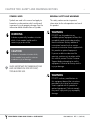
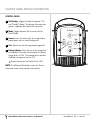
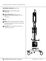
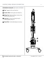
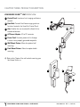
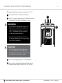
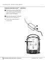
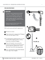
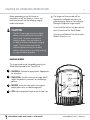
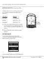
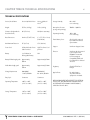
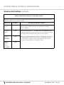
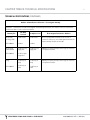
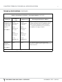
1
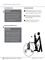
USER GUIDE VeinViewer® Vision VeinViewer® VisionXTND 020-300036-03 Rev. 1 (2012-09) Quick Reference Tips for: VeinViewer® Vision VeinViewer® VisionXTND Use Vision’s exclusive ASSESSTM Imaging Suite to find the optimal vessel while keeping your Eyes On Patient.TM Powering (Chapter 5, Page 20) • Vision: Press Projector Power Switch located on the Battery Cover. Press the On/Standby button located on the Control Panel.. • VisionXTND: Focusing (Chapter 6, Page 24) •The proper focal distance from the Head Unit to the assessment area is 13 inches (33cm). There is a 1 inch (2.54 cm) window in either direction where the image will remain in focus. • Position the Head Unit as close to perpendicular (90°) as possible with the assessment area. • Placing the Head Unit close to the patient skin, move away until the border text becomes legible. Imaging (Chapter 6, Page 25) •Once in focus, choose the desired imaging mode by pressing the Mode button: -Universal - baseline imaging mode for all patients. -Fine Detail - enhances small details to bring out finer vessels. Helpful for pediatrics, neonates or sclerotherapy patients • Size - adjusts the image window to three different sizes. •Inverse - inverts the colors within the image field to project green veins on a dark background. For further assistance with VeinViewer®, refer to the Troubleshooting section (Chapter 11) of this User Guide. Or call Christie Medical Holdings, Inc. Customer Service at 1-877-SEE-VEIN (1-877-733-8346) toll-free (+01-901-721-0330 international), or e-mail [email protected]. VE IN V IEWER VI SI ON AND V IS IO N X T N D US ER GUIDE 020-300036-03 rEV. 1 (2012-09) TABLE OF CONTENTS 1 CHAPTER ONE: INTRODUCTION ................................................................................................................ 3 Intended Use......................................................................................................................................................... 3 Conventions Used.............................................................................................................................................. 3 CHAPTER TWO: SAFETY AND WARNINGS ................................................................................................. 4 SYMBOLS USED........................................................................................................................................................ 4 GENERAL SAFETY and warnings....................................................................................................................... 4 Symbol Definitions............................................................................................................................................. 7 CHAPTER THREE: PRODUCT DESCRIPTION ............................................................................................... 8 Detachable Parts................................................................................................................................................ 8 Control Panel..................................................................................................................................................... 9 VeinViewer Unit: Front view........................................................................................................................... 10 VeinViewer Unit: back view............................................................................................................................. 11 VeinVieweR VISIONXTND Unit: Front view........................................................................................................ 13 CHAPTER FOUR: PRODUCT SET-UP .......................................................................................................... 14 MOVING PROCEDURE: VEINVIEWER.................................................................................................................... 14 PRODUCT SET-UP: VeinVieweR VISIONXTND......................................................................................................... 15 INSTALLING VeinVieweR VISIONXTND OPTIONAL DESK MOUNT........................................................................ 15 INSTALLING VeinVieweR VISIONXTND................................................................................................................... 17 CHAPTER FIVE: START-UP PROCEDURE ................................................................................................... 19 POWERING VeinViewer....................................................................................................................................... 19 POWERING VeinVieweR VISIONXTND..................................................................................................................... 21 CHAPTER SIX: OPERATING INSTRUCTIONS ............................................................................................. 23 FOCUSING procedure........................................................................................................................................ 23 IMAGING MODES .................................................................................................................................................. 24 CHAPTER SEVEN: DEVICE DISPLAY MESSAGES........................................................................................ 25 PROJECTED IMAGE DISPLAY................................................................................................................................ 25 BATTERY/LED INDICATOR .................................................................................................................................... 26 SOFTWARE VERSION ............................................................................................................................................ 26 CHAPTER EIGHT: SHUTDOWN PROCEDURE............................................................................................. 27 POWERING DOWN VeinViewer.......................................................................................................................... 27 POWERING DOWN VeinVieweR VISIONXTND........................................................................................................ 28 VE IN V IEWER VI SI ON AND V IS IO N X T N D US ER GUIDE 020-300036-03 rEV. 1 (2012-09) TABLE OF CONTENTS 2 CHAPTER NINE: MAINTENANCE .............................................................................................................. 29 Cleaning.............................................................................................................................................................. 29 BATTERY CARE....................................................................................................................................................... 30 CHAPTER TEN: SERVICE & SERVICEABILITY ............................................................................................ 31 CHAPTER ELEVEN: TROUBLESHOOTING ................................................................................................. 32 CHAPTER TWELVE: TECHNICAL SPECIFICATIONS ................................................................................... 37 CHAPTER THIRTEEN: LIMITED WARRANTY .............................................................................................. 43 VE IN V IEWER VI SI ON AND V IS IO N X T N D US ER GUIDE 020-300036-03 rEV. 1 (2012-09) CHAPTER ONE: INTRODUCTION 3 Please carefully read the information in this User Guide in its entirety and review these materials periodically to ensure that you will be able to use VeinViewer® confidently and correctly. as blood within vessels (e.g., veins), the blood flowing through the vessels (e.g., venous refill), and/or blood within the interstitial space (e.g., hematoma). This User Guide is a reference for using VeinViewer Vision and VisionXTND. It does not provide training in venous identification or clinical practices. The User Guide covers the preparation and use of VeinViewer and includes a table of contents to help you find the information you need. If additional information is needed, contact Christie Medical Holdings, Inc. at www.VeinViewer.com, e-mail info@ VeinViewer.com or call the VeinViewer Support Center toll-free at 1-877SEE-VEIN (1-877-7338346). For international calls, dial +01-901-7210330. The projected image pattern may also be used to demonstrate intravenous (IV) fluids displacing blood during IV flushes. Intended Use VeinViewer® Vision family is a non-invasive, electro-optical visual aid device designed to detect superficial blood under the skin, and project an image of that blood pattern onto the surface of the skin of neonatal, pediatric, and adult patients. Indications for Use VeinViewer® Vision family is intended to image subcutaneous blood patterns on the surface of the skin. The projected blood patterns may be interpreted by the clinician to determine intravascular or interstitial blood patterns, such VE IN V IEWER VI SI ON AND V IS IO N X T N D US ER GUIDE VeinViewer is intended to be used by trained Health Care Professionals including, but not limited to, Licensed Doctors, Nurse Practitioners (non-CRNA), Emergency Medical Technicians, Registered Nurses, Anesthesiologists, Vascular Access Technicians and Phlebotomists, Infusion Nurses, to perform vascular access. CONTRAINDICATIONS VeinViewer® is not intended to be used for imaging of veins in the eyes, in tissue differentiation, as a diagnostic device or as a form of treatment. VeinViewer® is not intended to be used near equipment that may emit strong magnetic fields (i.e., MRI equipment). VeinViewer® is not intended to be used to diagnose or verify the presence of a medical condition. VeinViewer® is not to be used outside or in direct sunlight. 020-300036-03 rEV. 1 (2012-09) CHAPTER TWO: Safety and Warnings Notices SYMBOLS USED GENERAL SAFETY and WARNINGS Symbols are used in this manual and apply to hazards or unsafe practices which could result in personal injury or property damage. See the information below for definitions of symbols. This safety section contains important information for the safe operation and use of this product. WARNING Indicates a potentially hazardous situation which, if not avoided, could result in serious injury or loss of life. CAUTION Indicates a hazardous situation which, if not avoided, may result in minor or moderate injury or damage. ! 4 Gives important recommendations and information for efficient, trouble-free use. WARNING DO NOT use this product or any available optional equipment without first completely reading and understanding these instructions and any additional instructional material such as service manuals or instruction sheets supplied with this product or optional equipment. If you are unable to understand the warnings, cautions or instructions within this manual, contact Christie Customer Support before attempting to use this equipment. Failure to do so may result in injury or damage. WARNING DO NOT make any modifications to this equipment beyond the instructions provided in this manual or instruction sheets supplied with this product or optional equipment. Failure to comply may result in physical injury or property damage. VE IN V IEWER VI SI ON AND V IS IO N X T N D US ER GUIDE 020-300036-03 rEV. 1 (2012-09) CHAPTER TWO: Safety and Warnings Notices 5 ACCESSORIES WARNING CAUTION VeinViewer components are specifically designed and manufactured for use in conjunction with VeinViewer. • Christie endeavors to supply a wide variety of VeinViewer products to meet the needs of the end user and patient; however, interpretation and final application of VeinViewer rests solely on the healthcare professional using the device. Christie recommends that the healthcare professional rely on standard healthcare practices prior to starting or during any type of medical procedure. Accessories designed by other manufacturers have not been tested by Christie and are not recommended for use with VeinViewer products. DO NOT connect any other medical devices directly to the VeinViewer unit. This could cause unexpected failure of the device and the VeinViewer unit. • Do not touch, strike, or otherwise damage the glass lens of the Head Unit. Observe the following safety precautions to obtain maximum personal safety and to protect your VeinViewer. VeinViewer produces a bright light; however, it does not use a laser-based illumination system. CAUTION • Do not look directly into the imaging light source when the Head Unit power is on. • Due to the bright light output, provide the patient hospital issued eye protection when imaging neonatal patients or when imaging vasculature around the eyes or on the scalp. Refer to your institution’s guidelines concerning eye safety procedures. VE IN V IEWER VI SI ON AND V IS IO N X T N D US ER GUIDE 020-300036-03 rEV. 1 (2012-09) CHAPTER TWO: Safety and Warnings Notices 6 WARNING WARNING • Do NOT expose VeinViewer to excessive moisture, temperature, or direct energy sources such as heat lamps. • Do NOT attempt to lift the VeinViewer Vision. • Do NOT stand on the base of the VeinViewer Vision, this may result in device instability. • VeinViewer Vision may lose stability if tilted more than 10 degrees in the moving position or if tilted more than 5 degrees during normal use. • VeinViewer is not to be used near flammable agents or flammable anaesthetics mixtures with air or with oxygen or nitrous oxide. WARNING • Special precautions exist for VeinViewer regarding electromagnetic emissions (EMC). VeinViewer shall NOT be used adjacent to or stacked with other equipment. VeinViewer needs to be set-up and put into service according to the EMC information provided in the Technical Specifications in this User Guide. Failure to do so could result in an increase of electromagnetic emissions or decrease in electromagnetic immunity, and/or affect the safety and effectiveness of VeinViewer Vision, which could result in injury or damage. VE IN V IEWER VI SI ON AND V IS IO N X T N D US ER GUIDE CAUTION • VeinViewer may be used in an electromagnetic environment in which radiated RF disturbances are controlled. The user of VeinViewer can help prevent electromagnetic interference by maintaining a minimum distance between portable and mobile RF communications equipment (transmitters) and VeinViewer, as recommended in the VeinViewer Technical Specifications in Chapter 12, and according to the maximum output power of the communications equipment. 020-300036-03 rEV. 1 (2012-09) CHAPTER TWO: Safety and Warnings Notices Symbol Definitions SN Date of manufacture Caution I 0 Caution: Risk of electrical shock SN SN EC On/Off system power switch On/Standby Manufacturer SN SN SN 7 SN: Serial Number EC Protective Earth REP Authorized representative in the European community Transport symbol Operating Instructions Battery symbol Consult accompanying documentation. (This symbol appears blue on the product.) SN EC EC REP REP EC VE IN V IEWER VI SI ON AND V IS IO N X T N D US ER GUIDE REP 020-300036-03 rEV. 1 (2012-09) R CHAPTER Three: Product Description VeinViewer is designed for ease of use. VeinViewer utilizes visible and near-infrared light for vascular imaging to illuminate and project the subcutaneous blood patterns directly onto a patient’s skin. AVINTM (Active Vascular Imaging Navigation) allows the user to assess multiple access points with a real-time digital image. The adjustable head can be positioned over any part of the anatomy, leaving the clinician’s hands free to perform the procedure, our trademarked EOPTM (Eyes On Patient) technique. 8 Detachable Parts CAUTION Please make sure the following items are included with your VeinViewer unit. If any items are missing, contact your VeinViewer representative or Customer Support. Do NOT substitute any items with non-Christie items. Failure to comply may result in physical injury or property damage. • Model Name: VeinViewer Vision • Power Cord P/N: P01625 (Qty: 1) • User Manual • Model Name: VeinViewer VisionXTND • Head and Arm assembly • AC Power Adapter P/N: 002-120597-01 and Power Cord P/N: 012-101975-01 • Base Mount • Hardware: - 3/8 -16 x 1” Button head Cap (For optional Wall Mount) QTY: 1 - 3/32” Allen Wrench QTY: 1 - Rectangular Spacer QTY: 1 • User Manual Not included: • Torque wrench • Wall mounting hardware VE IN V IEWER VI SI ON AND V IS IO N X T N D US ER GUIDE 020-300036-03 rEV. 1 (2012-09) CHAPTER three: Product Description 9 CONTROL PANEL 1 On/Standby: Toggles the Head Unit between “On” and “Standby” Modes. The Indicator illuminates when power is supplied and the Head Unit is turned on. 2 Mode: Toggles between the Universal and Fine Detail Modes. 1 3 Inverse: Inverts the colors within the image field to project green veins on a dark background. 4 2 4 Size: Adjusts the size of the projected image field. 5 Battery Indicator: Alerts the user to the charge level 5 3 of the Battery. Illuminates solid red when the Battery charge level is at 25%. The indicator blinks red when the Battery charge level reaches 10%. ! Battery Indicator for VeinViewer Vision ONLY NOTE: The Mode and Size buttons access the Device Information screen when pressed simultaneously. VE IN V IEWER VI SI ON AND V IS IO N X T N D US ER GUIDE 020-300036-03 rEV. 1 (2012-09) CHAPTER Three: Product Description 10 VeinVieweR vision Unit: Front View 1 Control Panel: Location of unit imaging and feature controls. 2 Head Unit: Controls VeinViewer imaging and user functions located in the Head Unit Control Panel. 3 Arm: Enables the user to extend the Head Unit 2 vertically to the desired location. 3 4 Post: Supports the Yoke of the Unit and Unit accessories. 1 5 Basket: Provides storage of the User Guide and Power Cord when not in use. 4 6 Power Cord: Conducts power to Unit through insertion into a properly grounded receptacle. 7 Caution Label 5 7 6 CAUTION Maximum allowable basket weight is 2 lbs (1 kg). Do not exceed this weight limit as this may result in device instability and/or improper loading. Failure to comply may result in physical injury or property damage. VE IN V IEWER VI SI ON AND V IS IO N X T N D US ER GUIDE 020-300036-03 rEV. 1 (2012-09) CHAPTER Three: Product Description 11 VeinVieweR vision Unit: BACK View 8 Battery Cover: Location of the Projector Power Switch. 9 Projector Power Switch: Allows the user to toggle the VeinViewer power between “On” and “Off” mode. 10 Base 11 Wheel: Enables transport of VeinViewer. The Wheel Lock allows the user to lock the Wheel in order to halt movement of the Unit. 12 Serial Label: Contains product serial number and manufacturer information. 8 9 10 11 VE IN V IEWER VI SI ON AND V IS IO N X T N D US ER GUIDE 12 020-300036-03 rEV. 1 (2012-09) CHAPTER Three: Product Description 12 VeinVieweR vision Unit: BACK View (CONTINUED) 13 Yoke: Supports the Arm and Head Unit. 14 Interface Cable: Delivers power to the Head Unit. 15 Battery Case: Protects the Battery. Location of the Power Inlet and Ground Stud. 13 16 Power Inlet: Connects to the Power Cord for conducting power to the Unit. 17 Ground Stud: For biomedical department testing. 14 16 15 VE IN V IEWER VI SI ON AND V IS IO N X T N D US ER GUIDE 17 020-300036-03 rEV. 1 (2012-09) CHAPTER Three: Product Description 13 VeinVieweR VISIONXTND Unit: FRONT VIEW 1 Control Panel: Location of unit imaging and feature controls. 2 2 Head Unit: Controls VeinViewer imaging and user functions located in the Head Unit Control Panel. 3 Arm: Enables the user to extend the Head Unit to 1 3 the desired location. 4 AC Power Adapter: AC to DC converter. 5 Power Cord: Conducts power to Unit through insertion into a properly grounded receptacle. 6 Wall Mount Fixture: Allows for optional wall mounting. 4 7 Desk Mount Fixture: Allows for optional desk mounting. ! Refer to the Chapter 4 for wall or desk mounting your VeinViewer VisionXTND 6 5 7 VE IN V IEWER VI SI ON AND V IS IO N X T N D US ER GUIDE 020-300036-03 rEV. 1 (2012-09) CHAPTER four: PRODUCT SET-UP VeinViewer Vision CAUTION • Check all parts for shipping damage and inspect unit before using. In case of damage, DO NOT use VeinViewer and contact the Christie Technical Support department for further instruction. Failure to comply may result in physical injury or property damage. 14 moving Procedure 1 Center the Yoke so that it is in line with the Post. Ensure that the Head Unit is in line with the Arm, and fold the Arm against the Post. 2 Move the lever upward on Wheel locks to unlock the Wheels. All Wheels should turn freely and smoothly. 3 Holding the Post below the Yoke move VeinViewer to the desired location. MOVING VeinViewer VISION CAUTION • Do not place, hang, or otherwise apply weight to the unit arm, this may result in improper device loading and /or device instability. Failure to comply may result in physical injury or property damage. • Always put the Head Unit in the travel position, when moving the VeinViewer Vision. Failure to comply may result in physical injury or property damage. 1 2 3 VE IN V IEWER VI SI ON AND V IS IO N X T N D US ER GUIDE 020-300036-03 rEV. 1 (2012-09) CHAPTER four: PRODUCT SET-UP PRODUCT SET-UP for VeinViewer VIsionXTND WARNING • After installation or service and before any use, ensure that the Desk/Wall Mount is secure properly to the mounting surface, otherwise serious injury or loss of life could result. CAUTION • Check all parts for shipping damage and inspect unit before using. In case of damage, DO NOT use VeinViewer and contact the Christie Technical Support department for further instruction. Failure to comply may result in physical injury or property damage. 15 1 Install the 3/8 -16 screw through the large “L” Bracket, Base Plate, Holder, and Mount Column, as shown. 2 Torque the 3/8-16 Nut to 75 in-lbs (8.5 N-m). INSTALLING VEINVIEWER VISIONXTND 2 INSTALLING VEINVIEWER VISIONXTND OPTIONAL DESK MOUNT For your convenience, VeinViewer VisionXTND is packaged desk mount ready. For wall mounting, you will need to convert the desk mount to the wall mount configuration. Proceed to step 5. ! ! 1 Maximum desk thickness is 2.5 in (6.35 cm). A torque wrench is required to complete steps 2, 3 and 5. VE IN V I EWER VI SI ON A ND V IS IO N X T N D US ER GUIDE 020-300036-03 rEV. 1 (2012-09) CHAPTER four: PRODUCT SET-UP 16 OPTIONAL DESK MOUNT 3 Install the 3/8-16 x 7/8” Flat Socket Cap Screw through the small “L” bracket, as shown. Torque the screw to 75 in-lbs (8.5 N-m). 4 Place the Base on top of the Desk surface, as shown. 3 5 Install the 1/2-13 x 3" Socket Set Screw though the small "L" bracket and place the Rectangular spacer between the bottom of the desk surface and the Socket Set Screw. 4 6 Torque the Socket Set Screw to 75 in-lbs. (8.5 N-m), to secure the base to the Desk. WARNING • Do NOT mount the base to a cart or mobile device. • After installation or service and before any use, ensure that the Desk/Wall Mount is secure properly to the mounting surface, otherwise serious injury or loss of life could result. 5 6 VE IN V IEWER VI SI ON AND V IS IO N X T N D US ER GUIDE 020-300036-03 rEV. 1 (2012-09) CHAPTER four: PRODUCT SET-UP 17 MODEL: VeinViewer VisionXTND ! Wall Mounting Hardware is NOT included. WARNING • After installation or service and before any use, ensure that the Desk/ Wall Mount is secure properly to the mounting surface, otherwise serious injury or loss of life could result. • DO NOT mount VeinViewer VisionXTND to unsupported wall board. 1 INSTALLING VEINVIEWER VISIONXTND OPTIONAL WALL MOUNT 3 1 Install wall screws to large “L” Bracket as shown. Mounting holes are 5/16” (7.9 mm) in diameter. ! A torque wrench is required to complete step 3. 2 Install the 3/8 -16 x 1” Button head Cap through the large “L” Bracket, Base Plate, Holder, and Mount Column, as shown. 3 Torque the 3/8-16 Nut to 75 in-lbs (8.5 N-m). 2 VE IN V IEWER VI SI ON AND V IS IO N X T N D US ER GUIDE 020-300036-03 rEV. 1 (2012-09) CHAPTER four: PRODUCT SET-UP INSTALLING VEINVIEWER VISIONXTNDARM CAUTION • A pinch point exists between links in the arm. Refer to figure below for Pinch Points location. Pinch point may occur when positioning the arm to the desired location or when returning the folded position. • Make sure the hands and any part of the patient, user and bystanders are clear of all pinch points before positioning the arm or returning the arm to the folded position. 18 ! The Arm should be able to rotate freely and smoothly 3 Place the power supply in the Holder as shown. 1 2 WARNING • Please ensure the Arm has been properly secured to the Mount Column. If the Arm is not firmly secured, the VeinViewer VisionXTND may fall off and result in serious injury or loss of life. CAUTION • Do NOT lay the AC Power adaptor on a material that is sensitive to heat as the material may become damaged. 1 Install the Arm into the Mount Column, as shown. 2 Secure the Arm to the Mount Column using 3 the 3/32” Allen wrench, as shown. VE IN V IEWER VI SI ON AND V IS IO N X T N D US ER GUIDE 020-300036-03 rEV. 1 (2012-09) CHAPTER five: START-UP PROCEDURE Powering VeinViewer vision VeinViewer Vision may be operated by AC (electrical outlet) or battery power. ! VeinViewer Vision is shipped with a detachable Power Cord. The Power Cord supplied acts as the MAINS disconnect device, and is compliant for North American use. ! VeinViewer Vision comes included with a North American only Power Cord. For destinations other than North America, the distributor country or sales representative in the destination country is required to provide the appropriate, detachable medical-grade Power Cord. This medical-grade cord must be compliant with both the destination country’s power requirements, and the electrical requirements specified in the User Guide. VE IN V IEWER VI SI ON AND V IS IO N X T N D US ER GUIDE 19 WARNING • Inspect the Power Cord and Plug on a regular basis, to avoid the risk of electrical shock and/or fire hazard. If the Power Cord and plug are or appeared damaged, do NOT use the VeinViewer Vision unit, and immediately contact the Christie Technical Support department for further instruction. ! The VeinViewer Vision Battery comes partially charged and should be immediately ready for training purposes. It is recommended that you charge VeinViewer overnight before beginning regular continued use. 020-300036-03 rEV. 1 (2012-09) CHAPTER five: START-UP PROCEDURE 20 ! If operating by battery power, skip steps 1, 2 & 3. 1 Unwrap the Power Cord from the Basket. 2 Insert the receiver power plug into the port located 4 at the back of the Base of the Battery Case WARNING • To avoid the risk of electrical shock, the plug must be inserted into receptacles marked “Hospital Grade” or “Hospital Only.” The Protective Earth wire must not be removed or defeated. 2 • Ensure the Projector Power Switch is in the off position before inserting the plug into the wall receptacle CAUTION • Do NOT place the Power Cord where it can be tripped over or stepped on. If operating by battery power, always wrap the Power Cord around the basket. 3 Insert the pronged plug into a wall receptacle. 4 Press the top of the black Projector Power Switch located on the Battery Cover to turn the Unit on. VE IN V IEWER VI SI ON AND V IS IO N X T N D US ER GUIDE 020-300036-03 rEV. 1 (2012-09) CHAPTER five: START-UP PROCEDURE Powering VeinViewer visionXTND VeinViewer VisionXTND is operated by AC (electrical outlet). 21 ! Before you connect VeinViewer to a power source, ensure that the voltage rating of the AC adapter matches that of the available power source. WARNING • VeinViewer VisionXTND is shipped with an AC Power Adapter and a detachable Power Cord inside the container. The Power Adapter is rated specifically for VeinViewer VisionXTND. The Power Cord supplied acts as the MAINS disconnect device, and is compliant for North American use. • Inspect the AC Power Adapter and Power Cord on a regular basis, to avoid the risk of electrical shock and/ or fire hazard. If the AC Power Adapter and Power Cord appear damaged, do NOT use VeinViewer VisionXTND, and immediately contact the Christie Technical Support department for further instruction VE IN V IEWER VI SI ON AND V IS IO N X T N D US ER GUIDE CAUTION • Do NOT place the Power Cord where it can be tripped over or stepped on. ! The surface of the AC adaptor may become warm when in use but this condition does not indicate a malfunction. If you need to transport the AC adaptor, you should disconnect the Power Cord and let it cool before moving it. 020-300036-03 rEV. 1 (2012-09) CHAPTER five: START-UP PROCEDURE 22 Powering VeinViewer visionXTND (CONTINUED) 1 At initial setup connect the Power Cord to the AC adapter, and then plug the Power Cord into a wall receptacle. The Unit will power On when first plugged in. 2 After initial setup, press the “On/Stand By” Button once to turn VeinViewer on. ! The VeinViewer image will project in Universal mode. 1 2 VE IN V IEWER VI SI ON AND V IS IO N X T N D US ER GUIDE 020-300036-03 rEV. 1 (2012-09) CHAPTER six: Operating Instructions 23 FOCUSING Procedure CAUTION • The Head Unit must be positioned as closely as possible to a 90-degree angle, perpendicular to the surface of the patient's anatomy to be imaged, otherwise the projected image may appear skewed or distorted. The practitioner's line of sight should follow the projected imaging light as closely as possible. 1 • Always be aware of the Arm’s location when bending or stooping near the unit. 2 ! Ensure the system and Head Unit power are on. 1 Raise the arm as shown. 2 Position head so that it is perpendicular (90-degree) to the area to be imaged, as shown. ! The joint between the Head and the Arm is a 3-axis joint that allows 6 degrees of motion: vertically, horizontally, and rotating 180 degrees 3 13 in (33 cm) 3 Position the Head within a few inches of the Border Text is Clea of the image is clear and legible. Clear...... Current Mode 90˚ Text is Cle ar. Borde Product Name Border 4 Focus is achieved when the text around the border 4 r Text is assessment area and slowly move the Unit away to the focusing distance, approximately 13 inches (33 cm) from the unit lens to the target location. Border Text is Clear. Border Company Name VE IN V IEWER VI SI ON AND V IS IO N X T N D US ER GUIDE 020-300036-03 rEV. 1 (2012-09) CHAPTER six: Operating Instructions 24 Before proceeding to use VeinViewer on the patient, ensure VeinViewer is in focus, and familiarize yourself with the following imaging modes and features: CAUTION • The VeinViewer image may show a slightly different vessel width than the size of the actual vessel. This effect may vary from subject to subject, from one location of the body to another, and between imaging modes. Christie recommends that the healthcare professional rely on standard healthcare practices prior to starting or during any type of medical procedure. ! The Image and Inverse mode will be displayed in the border text within the projected image. (Refer to Device Display Messages Chapter for image sample). Inverse and Size features may be used with both Universal and Fine Detail Modes. Activating one Mode will turn off the other Mode if currently in use. IMAGING modes The image mode can be changed by pressing the Mode Button located on the Control Panel. 2 • UNIVERSAL: Standard imaging modes. Appropriate for all patients. 2 • FINE DETAIL: Used for viewing finer image details. 1 Helpful for pediatrics, neonates, or sclerotherapy patients. 3 • INVERSE: Inverts the color within the image to 4 2 5 3 project green veins on a dark background. 4 • SIZE: Adjusts projected image to one of three sizes. VE IN V IEWER VI SI ON AND V IS IO N X T N D US ER GUIDE 020-300036-03 rEV. 1 (2012-09) CHAPTER SEVEN: DEVICE DISPLAY MESSAGES 25 This section explains all of the messages that may appear while operating VeinViewer. PROJECTED IMAGE DISPLAY Inverse Mode Icon Current Mode Current Mode Product Name Product Name Inverse Mode !Icon Battery Charge Level (VeinViewer Vision ONLY. Icon permanently displayed for VisionXTND) Wall Power Icon Wall Power Icon Company Name Company Name VE IN V IEWER VI SI ON AND V IS IO N X T N D US ER GUIDE 020-300036-03 rEV. 1 (2012-09) CHAPTER SEVEN: DEVICE DISPLAY MESSAGES 26 BATTERY/LED INDICATOR (VeinViewer Vision ONLY) The Battery Indicator on the Control Panel of VeinViewer Vision indicates the charge level of the Battery when powered On. LED DISPLAY MESSAGE Solid Green Unit powered On Solid Red Battery Level < 25% Blinking Red Battery Level < 10% ! There is also a Battery Indicator symbol in the border text of the VeinViewer Vision’s projected image to the right of the Mode name. (Refer to image sample in this chapter). ! Refer to Battery Care Chapter for battery charging procedure. Battery Indicator software version The VeinViewer software version is displayed by simultaneously pressing the Mode button and the Size button located on the Control Panel. To exit the Software Version Screen press the Mode button. VE IN V IEWER VI SI ON AND V IS IO N X T N D US ER GUIDE 020-300036-03 rEV. 1 (2012-09) CHAPTER EIGHT: SHUTDOWN PROCEDURE POWERING DOWN VEINVIEWER VISION WARNING • Electrical safety hazard exists if the Unit is not disconnected from MAINS and Projector Unit is not turned off. 27 CAUTION • Before attempting to move VeinViewer, make sure it is not plugged into any receptacle. Wrap the Power Cord around the Basket as shown, to prevent any tripping hazards. 1 Press the “On/Stand By” Button once to turn off the VeinViewer Head Unit. ! VeinViewer should now be in Stand By mode. The “On/Stand By” indicator will turn off. The Battery display icon will remain green. 2 Press the top of the black Projector Power Switch located on the Battery Cover, in the off position. ! If the Projector Power Switch is off and the Unit is left plugged into a power receptacle, the system is charging. 3 Unplug the Power Cord from the power receptacle. ! The Unit is off when the Projector Power Switch is in the off position and the Unit is unplugged. VE IN V IEWER VI SI ON AND V IS IO N X T N D US ER GUIDE 020-300036-03 rEV. 1 (2012-09) CHAPTER EIGHT: SHUTDOWN PROCEDURE 28 POWERING DOWN VEINVIEWER VISIONXTND 1 Press the “On/Stand By” Button once to turn off the VeinViewer Head Unit. ! VeinViewer VisionXTND should now be completely off. The “On/Stand By” indicator will turn off. CAUTION • When VeinViewer is not in use, ensure Unit and Arm are folded towards the VeinViewer frame to prevent any type of injury and damage to the device. CAUTION • A pinch point exists between links in the Arm. Refer to Pinch Points on page 19. Pinch Points may occur when positioning the Arm to the desired location or when returning the Arm to the folded position. • Make sure the hands and any part of the patient, user and bystanders are clear of all Pinch Points before positioning the Arm or returning the Arm to the folded position. VE IN V IEWER VI SI ON AND V IS IO N X T N D US ER GUIDE 020-300036-03 rEV. 1 (2012-09) CHAPTER nine: maintenance Cleaning This section is intended to assist you in effective cleaning of VeinViewer. It is also intended to protect the delicate VeinViewer components during the cleaning process. For more information about the compatibility of cleaning solutions for VeinViewer, please contact Christie or your local VeinViewer representative. Failure to adhere to the following recommendations could damage the Unit and void the warranty. WARNING • Always press the System Power Switch off and disconnect the VeinViewer Power Cord from the electrical outlet before cleaning. Failure to do so may affect the safety and effectiveness of VeinViewer. CAUTION • Do not clean the glass lens with cleaning products or solutions other than 70% isopropyl alcohol. • Do NOT use solvents or abrasive cleaners on any part of the Unit. Products and solutions other than those recommended may damage the Unit and will void the warranty. 29 CAUTION • Do NOT spray cleaners or pour liquids directly onto the Unit surfaces. Doing so may cause excessive fluids to enter and potentially damage the Unit. • Christie recommends the use of protective eyewear and gloves when cleaning the Unit. Refer to your individual institution’s policy and procedure for use of personal protective equipment while cleaning medical devices. NOTE: Cleaning methods listed are recommended for compatibility with Unit materials. Cleaning frequency should be performed in accordance with your individual institution’s infection control guidelines. Lens 1 The VeinViewer lens should be cleaned with a lint-free cloth moistened with 70% isopropyl alcohol ONLY. 2 Allow to air-dry or towel-dry with a clean, lint-free cloth. VeinViewer Body 1 Use a SANI-CLOTH® PLUS, or CaviWipes®, or 1:10 Bleach Wipes to wipe down all of the VeinViewer exposed surfaces. 2 Allow to air-dry or towel-dry with a clean, lint-free cloth. VE IN V IEWER VI SI ON AND V IS IO N X T N D US ER GUIDE 020-300036-03 rEV. 1 (2012-09) CHAPTER nine: MAINTENANCE BATTERY CARE – VEINVIEWER VISION ONLY WARNING • Do NOT attempt to open, disassemble, replace the Battery or service the Power Supply compartment. VeinViewer Vision shall only be serviced by authorized service representatives. Failure to do so could result in electrical shock, serious injury or loss of life. Estimated Battery continuous run time: 2.5-3 hours. Number of uses assuming 2.5 minutes per use: estimated 70 uses before needing recharge. Recharge Time: estimated at 40% of a total charge in 1 hour, complete charge estimated at 4 hours recharge time. To recharge VeinViewer, plug the Power Cord into the Power Inlet on the Battery Case and a standard AC power outlet. The Unit does not need to be powered on in order to charge. Device may be used while recharging. Placing Vision in standby mode when not in use helps to preserve the battery life. When you have finished charging the Battery, unplug Power Cord and wrap it around the Cable Holder. 30 Optimum battery storage is achieved at room temperature. The battery will prevent further charge or discharge if exposed to high temperatures. It is recommended that the battery is recharged if it is stored longer than 6 months. ! To ensure safe use of VeinViewer, periodic preventive inspection and maintenance need to be performed by an authorized service representative in accordance to VeinViewer Vision Service Manual 020-100932-XX. DISPOSAL Please ensure that VeinViewer, and its accessories are properly disposed of, as inappropriate waste handling of this product may cause potential hazards to the environment and human health. Do NOT expose to fire, or dispose of in fire. For more detailed information about recycling of this product, please follow your institution’s guidelines or contact your waste disposal service or Christie Technical Support. NOTE: Always keep the Power Cord with the VeinViewer Vision unit. WARNING • Do not store VeinViewer Vision in temperatures above 60°C/140°F. VE IN V IEWER VI SI ON AND V IS IO N X T N D US ER GUIDE 020-300036-03 rEV. 1 (2012-09) CHAPTER ten: SERVICE & SERVICEABILITY Christie is committed to helping you get the greatest value from the use of your VeinViewer. While VeinViewer is of high quality, we do realize that from time to time, you may need support for technical or user issues. We are more than happy to help. Please use the Troubleshooting chapter to determine the answer to your question, or contact the VeinViewer Support Center by telephone, by e-mail, or online. VeinViewer Support Center Hours: Monday – Friday 8:00 a.m. – 5:00 p.m. CST Email: Email is accepted on a 24-hour basis. [email protected] 31 serviceability Unauthorized or improper use of VeinViewer will void the limited warranty. Service may be done by an authorized Christie representative. See limited warranty (Chapter 13) for situations where warranty is voided. Christie is committed to the quality of our products. You can reach our VeinViewer Support Center with any questions or comments regarding service contract options, in-service training, sales, or support by visiting www.veinviewer.com, emailing [email protected], or by calling 1-877-SEE-VEIN (1-877-733-8346 toll-free). For international calls, dial +01-901-721-0330. Web site: www.veinviewer.com Telephone: 1-901-721-0330 1-877-SEE-VEIN (1-877-733-8346 toll-free) International: +01-901-721-0330 Fax: 1-901-721-0350 International: +01-901-721-0350 VE IN V IEWER VI SI ON AND V IS IO N X T N D US ER GUIDE 020-300036-03 rEV. 1 (2012-09) CHAPTER ELEVEN: TROUBLESHOOTING ? VeinViewer Vision system power will not turn on. ✓ 1 M ake sure that the VeinViewer Battery has been charged. 2 If the Battery does not have sufficient charge, you may operate VeinViewer Vision by plugging the Power Cord into a hospital grade or Hospital Only power receptacle. 3 P ress the top of the Projector Power Switch (symbol) to turn on. 32 ? The Head Unit power will not turn on. • No imaging light. • No Battery status indicator light. • No illumination from the Head Unit On/Standby indicator. • No audible hum from fan inside the Head Unit. ✓ 1 C heck for damage to cables. 2 C heck that the Power Cord is firmly plugged into the wall and into the Unit. 3 F lip the Projector Power Switch to power VeinViewer on and off. ? System power shuts down (turns itself off). 4 P ress the Head Unit On/Standby button. ✓If this occurs, please press the Projector 5 Verify that the System Ready indicator is illuminated and steady. Power Switch into the off position and contact the VeinViewer Support Center for assistance. VE IN V IEWER VI SI ON AND V IS IO N X T N D US ER GUIDE 020-300036-03 rEV. 1 (2012-09) CHAPTER eleven: TROUBLESHOOTING ? Flashing Indicators: Battery Indicator • Both green and red LEDs flashing. ✓ The Battery Indicator will flash rapidly if there is a loss of communication. 1 P ower off VeinViewer. 2 P ower on VeinViewer. 3 If the Battery indicator is still flashing, please call the VeinViewer Support Center for assistance. ? Solid Indicators: On/Standby Indicator and Battery Indicator • Green On/Standby Indicator and both Battery Status Indicators are illuminated. • Imaging light unexpectedly turns off. • Plastic shell of the Head Unit is hot to the touch. 33 ? Head Unit power will not turn on. • Red LED flashing or not illuminated. • Unit shuts down on its own or shortly after a full charge cycle when running on battery power. ✓A flashing red LED indicator while the Projection Unit is on means the Battery needs recharging immediately. 1 P ower off VeinViewer and connect it to AC power. Let it charge overnight for a full charge. 2 P ower on VeinViewer and check Battery Status indicator light. It should be solid green. 3 U se VeinViewer normally. If the red LED light begins to flash shortly after a full charge cycle, this may indicate that the Battery needs to be replaced. • Button pad is unresponsive. ✓ 1 Power off VeinViewer and wait 20 minutes. 2 P ower on VeinViewer. 3 If all the status indicators become illuminated again, this is a sign of overheating. Please shut down the Unit and call the VeinViewer Support Center for assistance. VE IN V IEWER VI SI ON AND V IS IO N X T N D US ER GUIDE 020-300036-03 rEV. 1 (2012-09) CHAPTER eleven: TROUBLESHOOTING 34 ? Feature Buttons: Mode, Inverse, Size. • No visible change in the image field or functionality when a feature button is pressed. ✓ 1 P ress alternate Keypad buttons to verify Keypad functionality. If there is no Keypad functionality, proceed to the Head Unit power solution. 2 M ake sure your finger is flush with Feature button. 3 P ress the Feature button, making sure it is fully depressed. ? Projected image appears out of alignment or unclear. ✓ 1 Verify that the protective film has been removed from the Head Unit lens. 2 Verify image focus: Move the Head Unit up or down in order to obtain focal distance, approximately 13 inches (33 cm) from the target location. The border text around the image should be clear and legible. VE IN V IEWER VI SI ON AND V IS IO N X T N D US ER GUIDE 020-300036-03 rEV. 1 (2012-09) CHAPTER twelve: TECHNICAL SPECIFICATIONS 35 TECHNICAL SPECIFICATIONS Version, Model Name Version 2.0, Model Vision Version 2.0 Model VisionXTND Storage Humidity 0% to 90% non-condensing Weight 53.5 lbs. (24.3 kg) 19 lbs. (8.62 kg) Atmospheric Pressure (storage and operating) 700 hPa – 1,060 hPa Clearance (height with the Head Unit down) 60" (152.4 cm) N/A (Unit is stationary) Operating Humidity 10% to 90% non-condensing Base Dimensions 22x22 in (55.9x55.9 cm) Plastic Battery Cover Should only be removed by an authorized Christie representative. Support VeinViewer Support Center Emission VeinViewer has been tested to and complies with IEC60601-1-2 standard for Electromagnetic Compatibility (EMC) and for radiated and conducted emissions. 6" x 5.5" (15.3 x 14 cm) (Desk Mount) Arm Maximum Extension 25” (63.5 cm) 35.6" (90.4 cm) Power Cord US Medical Grade Power Cable Provided High Flex Power Cord provided Battery 6 cell Lithium Ion Rechargeable Battery N/A Battery IR Wavelength, peak Approximately 850 nm Approximately 850 nm Visible Wavelength, peak Approximately 530 nm Approximately 530 nm Regulatory Classified FDA Class 1 Exempt Voltage Requirements 100-240VAC, 1.3-0.7A, 50-60Hz 100-240 VAC, 0.6 - 0.4 A, 50-60 Hz Applied Parts Duty Cycle Continuous Continuous No applied parts – any contact with the equipment is incidental. Operating Temperature +60°F to +90°F (+16°C to +30°C) +60°F to +90°F (+16°C to +30°C) Storage Temperature -10°F to +140°F (-23°C to +60°C) -10°F to +140°F (-23°C to +60°C) VE IN V IEWER VI SI ON AND V IS IO N X T N D US ER GUIDE MEDICAL EQUIPMENT WITH RESPECT TO ELECTRICAL SHOCK, FIRE, AND MECHANICAL HAZARDS ONLY IN ACCORDANCE WITH UL60601-1 AND IEC60601-1, CAN/CSA-C22.2 NO. 601.1. 020-300036-03 rEV. 1 (2012-09) CHAPTER twelve: TECHNICAL SPECIFICATIONS 36 TECHNICAL SPECIFICATIONS (CONTINUED) Guidance and manufacturer’s declaration – electromagnetic emissions VeinViewer® is intended for use in the electromagnetic environment specified below. The customer or the user of VeinViewer should ensure that it is used in such an environment. Emissions Test Compliance Electromagnetic Environment – Guidance RF emissions CISPR 11 Group 1 VeinViewer uses RF energy only for its internal function. Therefore, its RF emissions are very low and are not likely to cause any interference in nearby electronic equipment. RF emissions CISPR 11 Class A VeinViewer 2.0 Vision and VisionXTND are suitable for use in all establishments, other than domestic establishments and those directly connected to the public low voltage power supply network that supplies buildings used for domestic purposes. Harmonic emissions IEC 61000-3-2 Class A Warning: This equipment/system is intended for use by healthcare professionals only. This equipment/system may cause radio interference or may disrupt the operation of nearby equipment. It may be necessary to take mitigation measures, such as reorienting or relocating VeinViewer or shielding the location. Voltage fluctuation/ flicker emissions IEC 61000-3-3 Complies VE IN V IEWER VI SI ON AND V IS IO N X T N D US ER GUIDE 020-300036-03 rEV. 1 (2012-09) CHAPTER twelve: TECHNICAL SPECIFICATIONS 37 TECHNICAL SPECIFICATIONS (CONTINUED) Guidance and manufacturer’s declaration – electromagnetic immunity VeinViewer® is intended for use in the electromagnetic environment specified below. The customer or the user of VeinViewer should ensure that it is used in such an environment. Immunity Test IEC 60601 Test Level Compliance Level Electromagnetic Environment – Guidance Electrostatic discharge (ESD) ±6 kV contact ±6 kV contact IEC 61000-4-2 ±8 kV air ±8 kV air Electrical fast transient/burst ±2 kV for power supply lines ±2 kV for power supply lines MAINS power quality should be that of a typical commercial or hospital environment. IEC 61000-4-4 ±1 kV for input/ output lines Surge ±1 kV line(s) to line(s) ±1 kV line(s) to line(s) MAINS power quality should be that of a typical commercial or hospital environment. IEC 61000-4-5 ±2 kV line(s) to earth ±2 kV line(s) to earth Floors or mount surface should be wood, concrete, or ceramic tile. If floors are covered with synthetic material, the relative humidity should be at least 30%. VE IN V IEWER VI SI ON AND V IS IO N X T N D US ER GUIDE 020-300036-03 rEV. 1 (2012-09) CHAPTER twelve: TECHNICAL SPECIFICATIONS 38 TECHNICAL SPECIFICATIONS (CONTINUED) Guidance and manufacturer’s declaration – electromagnetic immunity (CONTINUED) Immunity Test Voltage dips, short interruptions, and voltage variations on power supply input lines IEC 61000-4-11 Power frequency (50/60 Hz) magnetic field IEC 60601 Test Level Compliance Level <5% UT (>95% dip in UT) for 0.5 cycle <5% UT (>95% dip in UT) for 0.5 cycle 40% UT (60% dip in UT) for 5 cycles 40% UT (60% dip in UT) for 5 cycles 70% UT (30% dip in UT) for 25 cycles 70% UT (30% dip in UT) for 25 cycles <5% UT (>95% dip in UT) for 5 sec <5% UT (>95% dip in UT) for 5 sec 3 A/m 3 A/m Electromagnetic Environment – Guidance MAINS power quality should be that of a typical commercial or hospital environment. If the user of VeinViewer requires continued operation during power mains interruptions, it is recommended that VeinViewer be powered from an uninterruptible power supply or a battery. Power frequency magnetic fields should be at levels characteristic of a typical location in a typical commercial or hospital environment. IEC 61000-4-8 NOTE: UT is the AC MAINS voltage prior to application of the test level. VE IN V IEWER VI SI ON AND V IS IO N X T N D US ER GUIDE 020-300036-03 rEV. 1 (2012-09) CHAPTER twelve: TECHNICAL SPECIFICATIONS 39 TECHNICAL SPECIFICATIONS (CONTINUED) Guidance and manufacturer’s declaration – electromagnetic immunity (CONTINUED) Immunity Test IEC 60601 Test Level Conducted RF 3 Vrms IEC 61000-4-6 150 kHz to 80 MHz Compliance Level 3V Electromagnetic Environment – Guidance Portable and mobile RF communications equipment should be used no closer to any part of VeinViewer, including cables, than the recommended separation distance calculated from the equation applicable to the frequency of the transmitter. Recommended separation distance √P d=[1.17] √ d=[1.17] P 80 MHz to 800 MHz √ d=[2.33] P 800 MHz to 2.5 GHz Radiated RF 3 V/m IEC 61000-4-3 80 MHz to 2.5 GHz 3 V/m Where P is the maximum output power rating of the transmitter in watts (W) according to the transmitter manufacturer and d is the recommended separation distance in meters (m). Field strengths from fixed RF transmitters, as determined by an electromagnetic site survey,a should be less than the compliance level in each frequency range.b Interference may occur in the vicinity of equipment marked with the following symbol: VE IN V IEWER VI SI ON AND V IS IO N X T N D US ER GUIDE 020-300036-03 rEV. 1 (2012-09) CHAPTER twelve: TECHNICAL SPECIFICATIONS 40 TECHNICAL SPECIFICATIONS (CONTINUED) Guidance and manufacturer’s declaration – electromagnetic immunity (CONTINUED) NOTE 1: At 80 MHz and 800 MHz, the higher frequency range applies. NOTE 2: These guidelines may not apply in all situations. Electromagnetic propagation is affected by absorption and reflection from structures, objects, and people. a Field strengths from fixed transmitters, such as base stations for radio (cellular/cordless) telephones and land mobile radios, amateur radios, AM and FM radio broadcasts, and TV broadcasts cannot be predicted theoretically with accuracy. To assess the electromagnetic environment due to fixed RF transmitters, an electromagnetic site survey should be considered. If the measured field strength in the location that VeinViewer is used exceeds the applicable RF compliance level on preceding pages, VeinViewer should be observed to verify normal operation. If abnormal performance is observed, additional measures may be necessary, such as reorienting or relocating VeinViewer. b Over the frequency range 150 kHz to 80 MHz, field strengths should be less than 3 V/m. Interference VeinViewer has been tested to comply with IEC radiated and conducted electromagnetic interference limits and therefore is not expected to cause interference with other devices used in the healthcare marketplace. (See Equipment Classification.) VE IN V IEWER VI SI ON AND V IS IO N X T N D US ER GUIDE 020-300036-03 rEV. 1 (2012-09) CHAPTER twelve: TECHNICAL SPECIFICATION 41 TECHNICAL SPECIFICATIONS (CONTINUED) Recommended separation distances between portable and mobile RF communications equipment and VeinViewer® VeinViewer is intended for use in an electromagnetic environment in which radiated RF disturbances are controlled. The customer or the user of VeinViewer can help prevent electromagnetic interference by maintaining a minimum distance between portable and mobile RF communications equipment (transmitters) and VeinViewer, as recommended below, according to the maximum output power of the communications equipment. Separation Distance According to Frequency of Transmitter Rated Maximum Output Power of Transmitter m W 150 kHz to 80 MHz d= 3.5 V1 √P 80 MHz to 800 MHz d= 3.5 V1 √P 800 MHz to 2.5 GHz d= 0.01 0.12 0.12 0.23 0.1 0.37 0.37 0.74 1 1.17 1.17 2.33 10 3.69 3.69 7.38 100 11.67 11.67 23.33 7 E1 √P For transmitters rated at a maximum output power not listed on the preceding page, the recommended separation distance d in meters (m) can be estimated, using the equation applicable to the frequency of the transmitter, where P is the maximum output power rating of the transmitter in watts (W), according to the transmitter manufacturer. NOTE 1: At 80 MHz and 800 MHz, the separation distance for the higher frequency range applies. NOTE 2: These guidelines may not apply in all situations. Electromagnetic propagation is affected by absorption and reflection from structures, objects, and people. VE IN V IEWER VI SI ON AND V IS IO N X T N D US ER GUIDE 020-300036-03 rEV. 1 (2012-09) CHAPTER twelve: TECHNICAL SPECIFICATIONS EQUIPMENT CLASSIFICATION 42 Patents VeinViewer® is manufactured and sold under U.S. Patents 5,969,754 and 7,239,909. • Protection against electrical shock – Vision: Class I Equipment, with no applied part. • VisionXTND: Class II Equipment, with no applied part. • Protection against ingress of liquids – Ordinary. • Equipment is not suitable for use in the presence of a flammable anesthetic mixture with air or with oxygen or nitrous oxide. Mode of operation of equipment – Continuous Operation. [email protected] Web site: www.veinviewer.com Toll Free: 1-877-SEE-VEIN (877-733-8346) International: +01-901-252-3700 MEDICAL EQUIPMENT WITH RESPECT TO ELECTRICAL SHOCK, FIRE, AND MECHANICAL HAZARDS ONLY IN ACCORDANCE WITH UL 60601-1, AND CAN / CSA-C22.2 NO. 601.1-M90 33MX RATING: 100 - 240 VAC 50-60Hz 1.3 - 0.7A PRODUCT NAME: VeinViewer Vision MODEL NO: 134-001102-01 0123 SN: Emergo Europe Molenstraat 15 2513 BH, The Hague The Netherlands Tel: (+31) 70 345 8570 Fax: (+31) 70 346 7299 MADE IN AUSTRIA PATENT NUMBER: 5,969,754 PATENT NUMBER: 7,239,909 Christie Medical Holdings Inc. 1256 Union Avenue, Memphis, TN 38104 P01614 REV 3 [email protected] Web site: www.veinviewer.com D VE IN V IEWER VI SI ON AND V IS IO N X T N(877-733-8346) US ER GUIDE Toll Free: 1-877-SEE-VEIN International: +01-901-252-3700 020-300036-03 rEV. 1 (2012-09) CHAPTER thirteen: LIMITED WARRANTY 43 Contact Christie Medical Holdings, Inc. for Standard Limited Warranty and Terms and Conditions. VE IN V IEWER VI SI ON AND V IS IO N X T N D US ER GUIDE 020-300036-03 rEV. 1 (2012-09) This page left intentionally blank. Federal Law restricts this device to sale by or on the order of a healthcare practitioner. Christie Medical Holdings, Inc. | 1256 Union Avenue | Memphis, TN 38104 | USA Emergo Europe Molenstraat 15 2513 BH, The Hague The Netherlands Phone: +31.70.345.8570 Fax: +31.70.346.7299 ©2011-2012 Christie Medical Holdings, Inc. 020-300036-03 Rev. 1 (2012-09)