1
WARRANTY
LIMITED
Polyvend Inc. warrants this equipment to the ORIGINAL PURCHASER only, for a
period of one (1) year from the date of shipment to be free from significant defects in
material or workmanship, three (3) years on the control board, five (5) years on the vend
motors to the extent such parts are warranted to Polyvend Inc., except for starters, light
bulbs and fuses which will be warranted for two months from date of shipment.
Should any part prove defective within the warranted period, Polyvend Inc. will repair or
replace (at its option) the defective component, but will not provide the labor, removal or
reinstallation cost associated with such parts. All returned products or parts must be shipped
freight prepaid to Polyvend and Polyvend will then prepay the shipping cost of the
returned goods. Polyvend Inc. reserves the right to refuse any collect ship~ent. Any part
returned under the terms of this warranty should be accompanied with a brief description
of the defect or failure along with the model number and serial number.
This warranty applies only if the equipment is serviced and maintained in strict
accordance with the instructions given in the Polyvend Service Manual, that no
unauthorized repair or disassembly has been done. Any defect caused by improper source
of power supplied, abuse of the product, accident, alteration, vandalism, mineral buildup or improper cleaning or service techniques will not be covered by warranty.
Polyvend service or repair to items not in warranty will be subject to the standard service
charge for repair of the failed components. For warranty of service information call or
write to Polyvend Service Department.
TABLE OF CONTENTS
PAGE
WARRANTY
A
GENERAL INFORMATION
1
SPECIFICATIONS
1
ELECTRICAL SPECIFICATIONS
1
INSTALLATION
2-4
PRODUCT LOADING
5-6
SPECIAL PRODUCT LOADING
GUM AND MINT TRAY LOADING (NEW STYLE ASSEMBLY)
7
8-9
PRIMARY CABINET COMPONENT INFORMATION
10-11
ELECTRICAL SERVICE SECTION
12-13
DETAILED CONTROL BOARD OPERATION
14-15
SHIPPING POLICY
16-17
DRAWINGS AND PARTS LISTS
19
SLIDING DRAWER ASSEMBLY
20-21
SLIDING DRAWER ASSEMBLY ELECTRICAL
22-23
MAIN CABINET WIRING
24-25
SNACK TRAY ASSEMBLY 4-SELECTION (REMOVABLE DIVIDERS)
26A-27A
CANDY TRAY ASSEMBLY 8-SELECTION (REMOVABLE DIVIDERS)
28A-29A
SNACK TRAY ASSEMBLY 4-SELECTION (FIXED DIVIDERS)
26-27
CANDY TRAY ASSEMBLY 8-SELECTION (FIXED DIVIDERS)
28-29
MAIN CABINET ASSEMBLY
30-32
HELIX ASSEMBLY
33
SERVICE DOOR ASSEMBLY
34-35
PRODUCT DELIVERY COMPARTMENT ASSEMBLY
36-37
NEW STYLE GUM & MINT ASSEMBLY
38-39
POWER BOX ASSEMBLY
40-41
LIGHT FIXTURE
42-43
POWER BOX SCHEMATIC
44
COMPLETE ELECTRICAL MACHINE SCHEMATIC
45
-~~~~~~~~-~~H~~~~
POLYVEND ULTRAVENDOR 32
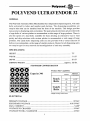
GENERAL
The Polyvend Automatic Helix Merchandiser has independent dispensing units, with each
helix activated by letter and number push buttons. The dispensing assemblies are
snap-in hubs that can be installed from the front of the machine. This design provides
easy access to displaying units on location. The pastry/snack selections are provided with
a large helix of various pitches to accommodate a wide range of large products. There is
also the option of a dual helix available for those desiring an alternative way to vend
pastry and chip selections with various pitches to accommodate a wide range of large
products. The candy helix dispensing units are also provided with a varied selection of
helices to accommodate a wide range of smaller products. Motors for all dispensing units
are snap-in type for easy removal and reconfiguration of each tray assembly.
SPECIFICATIONS
HEIGHT
72"
WIDTH
31 1/2"
DEPTH
28 1/2"
SHIPPING WEIGHT
(approx.) 520 lbs.
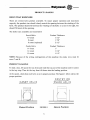
STANDARD CONFIGURATION
0000
0000
Product Size Capability
Capacity 346
~~~~
~
Snack
Helix
CD ~ CD e CD e IG)
e ~ e e e e 19 9
~~0
I~ ~
Candy
0
Helix
COUNT
PRODUCT
THICKNESS
10
1 1/2"
8
1 7/8"
14
12
1"
1 1/4"
10
1 1/2"
**Subject to change without notice.
ELECTRICAL
PRIMARY VOLTAGE
SECONDARY VOLTAGE
MAX. CURRENT
VOLTAGE TO CHANGER
VOLTAGE TO BILL VALIDATOR
110VAC
10.8/24VAC
3AMP
24VAC
24VAC
1
CAUTION: DISCONNECT POWER TO THE VENDING MACHINE BEFORE
REMOVING THE CONTROL BOARD, COIN CHANGER OR VALIDATOR OR
WORKING ON ANY ELECTRICAL COMPONENTS IN THE MACHINE.
INSTALLATION
*
Remove all external packing material.
*
Inspect equipment for shipping damage, if evident file claim immediately with the
carrier (See shipping procedures).
*
Remove keys from product dispensing compartment (in small manila envelope),
unlock the service door and remove the shipping cardboard.
*
Save extra fuses, etc. found in envelope as spare parts.
*
Check the operation of the service door and locking mechanism. They should
operate smoothly and latch at all three locking plates.
*
Place machine into position and adjust leveling legs so the machine is level and all
the legs sit firmly on the floor.
*
Cut the plastic ties holding each tray in position.
*
Plug service cord into 110VAC source using the three prong grounded plug
provided. If a grounded outlet is not available, use a proper external ground on all
locations.
NOTE: In order to comply with electrical safety regulations and Underwriters Laboratories requirements, all electrical equipment must be properly polarized and grounded. The
Polyvend machine is wired so that it is properly polarized in accordance with the
electrical code. If the wall outlet is wired and grounded properly, then the vending
machine will connect properly.
2
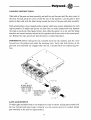
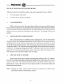
Shown in views A and B are two properly grounded and polarized wall outlets. One is a
three wire grounded type wall outlet (See View A) and the other is a two wire wall outlet
(See View B) with an adapter in place.
Should the polarity at the wall outlet appear any way other than that shown below, the
outlet should be rewired by qualified personnel.
THREE WIRE
GROUNDING TYPE
WALL OUTLET
TWO WIRE
WALL OUTLET
GROUND"
HOT
HOT
CIRCUIT GROUND
OR COMMON
CIRCUIT GROUND
OR COMMON
VIEW A
VIEWB
CAUTION: DISCONNECT POWER TO THE VENDING MACHINE BEFORE
REMOVING THE CONTROL BOARD, COIN CHANGER OR WORKING ON ANY
ELECTRICAL COMPONENTS IN THE MACHINE.
*
Check to ensure that power is present. Remelnber when you pull out the sliding
drawer, the safety interlock will shut off the power to the control board. To
re-energize the control board, pull the plunger out on the safety interlock switch
located at the back of the pull out drawer. For the location of safety interlock (See
figure 4 on page 10).
*
Test the coin mechanism and coin return assembly to insure smooth operation. If
the operation is not smooth, check to make sure that you have proper alignment of
the changer with the coin return lever.
*
Load the coin tubes on the coin changer located in the pull out sliding drawer. It is
very important to fill the 25¢, 10¢ and 5¢ tubes for proper changer payback.
Note~ The maxin1um amount of change a Coinco 9302LF changer will hold is
$38.60; $23.00 in quarters, $12.70 in dimes and $3.40 in nickels. The maximum
amount of change that a Mars TRC 6010XV will hold is $29.95; $16.75 in quarters, $9.80 in dimes and $3.40 in nickels.
3
*
*
Operate each dispenser, using coins. Operation should be smooth. Remember; the
safety interlock must be energized in order to test out the changer. To energize,
pull out the plunger on the safety interlock switch located at the back of the pull
out drawer (See figure 4 on page 10).
Load the machine with product (See section on product loading).
*
Place the price stickers on the trays to the right of the selection stickers. Set the
prices of the products (See price setting).
Note: To set the prices, the safety interlock switch must be energized by pulling
the plunger out located on the switch at the back of the pull out drawer.
*
Check to make sure that the Vend Options: forced vend and changer mode; are at
the desired setting (See detailed control board operation).
4
PRODUCT LOADING
HELIX TRAY DISPENSER
There are several helix pitches available. To insure proper operation and maximum
capacity, the product size should closely match the opening between the winding of the
helix. The product should fit between the windings of the helix so as not to be tight, but
should fill most of the opening.
The helix sizes available are listed below
Snack Helix
10 count
8 count
6 count (optional)
Product Thickness
1 1/2"
1 7/8"
2 1/2"
Candy Helix
14 count
12 count
10 count
Product Thickness
1"
1 1/4"
1 1/2"
NOTE: Because of the wiring configuration of this machine the candy rows must be
rows C and D.
PRODUCT LOADING
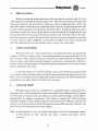
To load a tray, lift up on the tray front and slide the tray out of the machine until it comes
to the tray stop. Then let the tray front tilt down into the loading position.
At this point, check that each helix is in its proper position. The figure 1 below shows the
proper position.
PASTRY OR
SNACK HELIX
CANDY HELIX
candy
v
..
,
(
Detent Position
FIGURE 1
5
Detent Position
Starting at the front of the tray, insert a product between each winding of the helix so that
the name of the product is displayed forward. Be sure to place the product all the way to
the bottom of the tray and tilt free end at top backwards. Fill from front to back and be
sure not to miss any positions. Note: Product must rest on tray NOT on helix. After filling
the tray, lift the front of the tray and push it back in until the tray locks into place. Check
that the tray is fully latched in place by pulling forward on the tray and ensuring that the
tray does not advance beyond the latch.
6
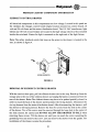
SPECIAL PRODUCT LOADING
NARROW PRODUCT LOADING
In order to keep narrow products positioned properly the use of one of the spacer guides
may be required. For additional guides order part no. 099-5107.
To install the guide, press on to the tray divider as shown in Figure 2 below.
c:=I
0
FIGURE 2
FLAT OR SEMI-FLAT BOTTOM PRODUCT LOADING INSTRUCTIONS
Note: Instructions apply to candy tray only.
Certain candies and cigarettes have a flat or semi-flat bottom which is thick and wide.
Polyvend Inc. has designed into our helix the flexibility to be 100% sure of the vending
of this type of product. By moving the position of the helix, and thus the helix kicker 90
degrees, the best dispensing for boxed products is insured. You simply unlock the helix
by pulling helix out of position. Turn the helix counterclockwise 95 to 100 degrees, then
engage and push helix in, to lock in place. The helix should then be in the position shown
below in Figure 3.
CANDY HELIX
KICKER 90 DEGREES FROM NORMAL FOR
TH ICK OR BOX TYPE PRODUCT.
candy
FIGURE 3
7
--h~ft~~~--------~-(OPTIONAL) GUM AND MINT TRAY LOADING
NEW STYLE SLIDE OUT DRAWER ASSEMBLY
The four select gum and mint dispenser is available in kit form or can be factory installed. All machines are prewired from the factory so you can install the gum and mint
kit at a later date. The harness for the gum and mint assembly plugs into the motor distribution board. This is the same board that the tray harness plugs into. Each selection will
hold up to 15 packs of gum (5 sticks per package) or roll candy up to 4 inches in length.
If a small diameter product of the anti-acid or breath mint type is to be vended it will be
necessary to use a pair of height adapters for each selection. These height adapters can be
ordered from your local distributor or from the Polyvend Parts Department. There are
two different heights available, the thinner adapter is normally used for anti-acid or breath
mints. The thicker adapter is used for very small diameter products or in some cases very
short rolls or packages of candy or gum. The short product will then go in between the
height adapters and act as a guide to keep them in position.
Each gum and mint assembly uses dividers that can be adjusted for the length of the
product to be vended. They can be moved by pushing the divider towards the rear of the
machine, unhooking the locking tabs and lift the divider upward. Move the divider closer
or farther apart depending on the length of the product to be vended. To lock the divider
in place allow the locking tabs on the divider to slip in the holes provided in the bottom
of the tray and pull the divider towards the front of the machine locking it in place.
NOTE: New style gum and mint units installed in machines with serial number 1811 and
higher.
8
LOADING INSTRUCTIONS
Take hold of the gum and mint assembly and pull the unit forward until the tray comes to
the stop. To load, push the cover toward the rear of the machine. Lay the gum or mint
packs on their side with the label facing toward the front of the gum and mint assembly.
Each selection has a clear, hinged product ejector which may require adjustment for each
type of product. To adjust this ejector, on each side is a small compression clip. Squeeze
the clips on each side (See figure below), then slide the ejector in or out until the hinge
knuckles are located entirely behind the first product and directly above the second product. Release the clips and ensure that the ejector is locked into place.
IMPORTANT: Before sliding the tray assembly back into the machine, pull the cover
forward over the product and under the retaining clips. Verify that both latches on the
gum and mint assembly are engaged after the tray is pushed back into dispensing position.
FLEX-TAB
~
GATE ADJUSTMENT
To adjust gate assembly front to rear depress flex-tabs as shown. Adjust gate assembly all
the way forward until gate hinge is directly over the second item to be vended. Adjust
gate assembly to the rear for larger product.
9
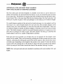
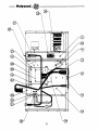
PRIMARY CABINET COMPONENT INFORMATION
SLIDEOUT CONTROL DRAWER
All electrical components in this compartment are low voltage. Located in this panel are
the validator, the changer, control board (digital readout mounted on control board), 10
volt and 24 volt fuses and the motor distribution board. The 110 VAC transformer, light
ballast and 110 volt circuit breaker are located in the high voltage electrical box mounted
beside the coin bank. Starter for light is mounted on the right end of the light fixture.
Note: The safety interlock switch that turns on the power to the drawer is located in the
rear, as shown in figure 4.
FIGURE 4
REMOVAL OF SLIDEOUT CONTROL DRAWER
With the service door open, pull the slideout drawer out to the stop. Reach up from the
storage area to the rear of the slideout drawer and unplug the harness connection from the
rear of the drawer. Note: The slideout drawer may have to be pushed partially closed, in
order to reach the back of the drawer and disconnect the wiring harness. Disconnect the
six tray harness from the motor distribution board. After disconnecting the harness, pull
the drawer to full open position. Remove the four (4) screws from the slide in the center
of the drawer. Two of the screws must be removed through the large hole in the center of
the slide section. Be careful and DO NOT ALLOW THE DRAWER TO FALL when
removing these screws. Tilt the drawer out until you can reach the screw mounting the
grounding wire and remove the screw. Lift and remove the drawer from the guides. For
installation of the drawer reverse the procedure.
10
HIGH VOLTAGE POWER SUPPLY
The high voltage power supply is located in the bottom of the machine, on the right hand
side beside the coin bank. The circuit breaker for the 110 volt circuits is located on the
top of the power supply. Also located inside the power supply are the ballast for the
fluorescent light, the step down transformer and the RFI filter. The starter for the fluorescent light is located on the right end of the light fixture.
STORAGE COMPARTMENT
The storage compartment is below the product display area and is accessed by opening
the front door. Additional products may be stored in this area. Be sure to leave room for
the delivery compartment when using the storage area.
HELIX TRAY REMOVAL
Lift up on the front of the tray and pull the tray out to the stop. Allow the tray to tilt down
into the loading position. Unplug the tray harness from the motor distribution board (located in the sliding drawer assembly) and set the harness on the tray you are removing.
Lift up on the tray front and pull the tray upward and outward. The tray can now be
removed from the machine for cleaning or service. To install the tray lift up on the front
of tray so that the back of the tray is lower than the front and slide the tray in. Reconnect
the tray harness in the drawer assembly.
NOTE: Because of the wiring configuration of this machine the candy rows must be
rows C and D.
TRAY HELIX REMOVAL
An individual helix can be renloved for cleaning, repair or replacement with a different
pitch whether the tray is in or out of the machine. A helix used with the new snap-in hub
feature can be removed by first grasping the helix close to the hub and pulling firmly on
the assembly toward the front of the tray.
To re-install the helix assembly, note that the snap-in shaft is square shaped, so the helix
must be properly positioned (product kicker in correct position). With the helix correctly
positioned, align the shaft of the hub with the octagon shaped nlotor drive and push the
helix into I?-lace. A positive lock in position will be felt when the shaft is properly inserted
and locked into place.
11
ELECTRICAL SERVICE SECTION
MODES OF OPERATION
The system will operate in one of two modes, sales or service. On power up (after completing configuration), the machine is in the sales mode. Service mode may be selected
by pressing the mode switch mounted on the control board. The system will return to the
sales mode if the mode switch is pressed or after 25 seconds of no service mode activity.
SALES MODE
In the sales mode, the control board will control the dispensing of products according to
customer credit and selection inputs. The control board will communicate with the coin
mechanism and dollar bill validator (if installed); so, as credit is entered it will be shown
on the digital display. If there is inadequate change available, the coin mechanism will
indicate that an exact change situation exists and the control board will illuminate
(continuously) the "EXACT CHANGE" L.E.D.
When a customer makes a selection on the key pad, buttons A thru D and (within 5
seconds) numbers 0 thru 9, the accumulated credit will be compared to the price set for
this selection and if the credit is equal to or exceeds the set price, the corresponding
motor will be energized. If the vend is successful, the price will be deducted from the
credit value and the change returned.
The vend will be considered unsuccessful if the motor does not receive sufficient current
or fails to reach the home position within six (6) seconds. The vend will not be attempted
if the motor has already been detected as failed or if the selection made is not in the
configuration of the machine. In any case, credit will not be deducted and the "MAKE
ALTERNATE SELECTION" L.E.D. will flash for 3 seconds or until a new selection is
made.
If there is insufficient credit for the selection made, the "CHECK PRICE" L.E.D. will
flash for 3 seconds or until more money is inserted or another keypad entry is made.
If power should fail during a vend, the credit will be lost and the selected motor will not
be re-energized when power returns, thus the next vend of this motor may be shorter than
normal.
12
SERVICE MODE
The service mode (S 1) can be entered by pressing the "MODE BUTTON" located on the
control board just below the two red buttons for the changer payout. Access is through a
hole on the back of the drawer assembly (See Figure 5). By using the numbers and letters
on the alphanumeric key pad, the operator can set the prices for the entire machine through
the control board. To the right of the mode button (See Figure 6) are two switches; one to
be used to turn the forced vend feature "on" (switch #1) and the other to turn the changer
mode feature "on" (switch #2). With both option switches 1 & 2 "on", when the service
vend mode button is pressed the control board will automatically be in the service vend
mode. Any other combination of these switches will enable the price setting function .
o
o
I- - -.- ••••••• -I
•
•
. -. -,.-
,.I •I
•
•
•
••
••
••
0
3 0
I
II
••
•••
•••
II II I
I, II I
.. _I .. _I
~_I~_'
2 :
;:,'!
•••
••
IIITTCII
•
a·
FIGURE 5
o
CONNECTOR
PERIPHERAL
____pi
o
PINS
PI
AC POWER
4
P2
BILL VALIDATOR
P3
CASH COUNTER
P4
CHANGER
11
P5
MOTORS
13
P6
KEYPAD
10
12
-..
7
13
o
FIGURE 6
~~~H~~~---------~
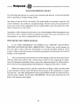
DETAILED OPERATION OF CONTROL BOARD
At the time of delivery from Polyvend Inc. the control board will be set as follows:
1.
All vend options will be off.
2.
All of the prices will be set to $0.50.
1.
COIN DISPENSING
While in the service mode the control board will payout coins out of the changer.
On the control board press the second button down from the top (button 52) for the changer
to payout nickels. To payout dimes press the top button (button 53). In order to payout
quarters press both of the payout buttons at the same time. The changer will payout
quarters.
2.
MOTOR/KEYPAD CONFIGURATION
This control board has two different motor configurations; one for 40 selections
(normally used in Polyvend equipment) and one used for 6 selections. To determine which
configuration the control board is setup for, press the mode button. Then press the letter
"E" and the digital display will show "40" which means the control board is setup for the
40 selection mode or "06" will show on the digital display if the control board is setup for
6 selections. To change the configuration from "6" selections, while in the service mode,
release the "E" selection button and press it again. The control board will change over to
"40" selections. Exit the service mode to lock in setting.
3.
SERVICE VEND OF MOTORS
Before going into the service mode turn both option switches to the "on" position.
Press the mode button, then press the letter and number of the motor you wish to service
vend (test vend). The motor should run until it returns to the home position. Upon completing the test vend of the motors reset the option switches to the desired setting and
then press the mode button.
Note: Changing the option switches while in the service mode has no effect on the
current mode until the mode button is pressed.
14
4.
PRICE SETTING
Before pressing the mode button one of the two options switches must be in the
"off" position or both option switches turned "off". Press the mode button, then press the
letter and number of the selection for which you wish to change the price. When you
press the number of that selection, release the button and press it again and the price will
go up in nickel increments. If you go past the desired price, release the button and press
the button in again. The price will go down in nickel increments. To change the price of
the next desired selection, press the letter and number of the selection. Release the number button and press it again. The price of that selection will go up. Repeat the procedure
for each selection. Upon completion, set the option switches to the desired setting and
press the mode button to lock in the prices and to return to the sales mode.
5.
FORCE VEND MODE
With this feature" on" , when a dollar bill is inserted the bill will be stacked and the
customer will have to make a vend. If any additional bill(s) are inserted the bill will be
held in escrow. When coins are inserted, a customer can make a purchase or if they press
the coin return, coins will be returned. Should a vend fail on a selection after a bill(s) is
inserted, the forced vend feature will be disabled and the customer can receive their money
back by hitting the coin return.
To turn this feature "on", turn the number 1 dip switch on the control board to the
"on" position. Press the mode button one time. Press the mode button again to lock in the
mode. Test the machine to ensure proper operation by inserting a one dollar bill and then
pressing the coin return. Then bill should not be returned.
6.
CHANGER MODE
With this feature turned "on" regardless of accumulated credit or maximum price,
the dollar bill(s) will automatically be sent to the stacker. Any additional bill(s) inserted
will be stacked. If you press the coin return you will receive the dollar(s) in the highest
denomination the changer can payout. If this feature is turned "off" (with escrowing
validator installed), the last dollar inserted will be held in escrow. When you hit the coin
return you will receive the last dollar bill inserted and any additional bill(s) inserted will
be in the form of change paid out by the changer.
Note: If hoth options are "on", the forced vend option will be the functioning feature.
If both options are "off", and the coin return is pushed, the money will be
returned.
15
POLYVEND SHIPPING POLICY
The following information is to assist you in assuring safe delivery of your merchandise
and in expediting of freight damage claims.
Our terms of sale are F.O.B. our factory. The responsibility for damage in transit is the
carrier's whether it be visible or concealed damage. We have taken every precaution to
ensure safe arrival of this equipment, but our responsibility ceases the moment the shipment is turned over to the carrier.
Acceptance of this shipment by the carrier is an acknowledgment that the equipment was
delivered to them in good condition and properly packed. The carrier who delivers this
merchandise to your door is responsible for its safe delivery.
PROCEDURE FOR VISIBLE DAMAGE
1.
IT IS VERY IMPORTANT TO INSPECT ALL FREIGHT DELIVERIES,
WHETHER MACHINE OR PARTS, IMMEDIATELY. If there is any visible damage you
have the right to either refuse the merchandise or accept the danlaged shipment. If you
accept it, make certain that you have the delivery personnel note the nature and extent of
damage on the freight bill.
2.
After you determine the extent and cost of the damage, notify the delivering carrier's
office by phone and confirm with a written notice within 15 days requesting an inspection of the damaged merchandise. Keep a copy of the inspection request for claim purposes.
Do not destroy the packing material until shipment is inspected and claim is settled.
3.
When the inspector arrives, ask for a claim form. In filing a claim, you may make
a cash settlement with the carrier for the full invoice price of the merchandise or contact
Polyvend Inc., and make arrangements to have merchandise returned for repair and file a
claim for repair charges. Do not return "DEADHEAD". Do not claim more than the cash
price of the machine, plus freight.
16
SHOCK WATCH PROCEDURES
On each machine shipped out of Polyvend Inc. there is an indicator called a Shock Watch,
which will turn from white to red if the machine has received a severe impact. The shock
watch is a red hexagon shaped label mounted on the front glass of the machine. Just
above the shock watch will be a label on the outside of the machine with instructions on
what to do when the machine is received and what to do if the shock watch has changed
color from white to red. Inspect the shock watch "IMMEDIATELY" upon receipt of the
machine. DO NOT SIGN THE BILL OF LADING until you have inspected the shock
watch to see if it has turned from white to red. If the shock watch has turned red note this
on the bill of lading. Inspect the machine "IMMEDIATELY" for damage both on the exterior and interior of the machine. If damage is found follow the procedures for concealed
danlage.
PROCEDURE FOR CONCEALED DAMAGE
1.
If there is no visible damage, YOU MUST OPEN THE SHIPMENT WITHIN 15
DAYS AND INSPECT FOR CONCEALED DAMAGE. If there is concealed damage, notify
the delivering carrier by phone immediately asking for an inspection. Confirm the request in writing and keep a copy for claim purposes. If you fail to notify the carrier
within 15 days of delivery by telephone and in writing, the freight company is no longer
liable for damage and will probably refuse your claim. Do not destroy packing material
until shipment is inspected and claim is settled.
After inspection by the carrier, file a claim for damages at once. On concealed
2.
danlage, unless it can be proven that the carrier is responsible for the damage, they will
probably want to settle on a compromise basis. Therefore, the faster you inspect your
delivery and notify the carrier, the better the chances for full settlement. If the claim is
disallowed, check on the possibility of a compromise.
PROCEDURES FOR SHORTAGES
1.
If the shipment delivered to you is not in accordance with the quantity of cartons
shown on your receipt, do not accept it until shortages are noted on the Freight Bill or
Bill of Lading and signed by the truck driver. Failure to do this releases the carrier from
any responsibility.
2.
If the shorted item(s) are not delivered within a reasonable time, file a claim with
the delivering carrier for the invoice or cash price of the item(s).
NOTE: Claims for loss or damage will NOT BE DEDUCTED FROM YOUR
INVOICE while you wait adjustment of such claims.
17
DRAWINGS AND PARTS LISTS
19
I
I
I
I
I
I
I
I
/
I
I
I
I
I
I
/
I
/
I
s
,
I
/
/ I
I I
I
,
,
I
,
/
/
I
I
I
/
I
I
/
I
I
I
I
I
/
/
,
If)
/
I
/
,
I
,
I
I
---L..~~~~,'~.'\.
,
/
I
I
I
~======~~
20
I
I
/
/
,
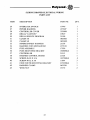
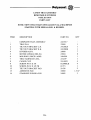
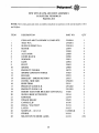
SLIDING DRAWER ASSEMBLY
PARTS LIST
ITEM
DESCRIPTION
PART NO.
QTY
1
2
3
4
5
6
7
8
9
10
11
12
13
14
15
16
17
18
19
20
21
22
23
24
25
DRAWER WIA
ESCUTCHEON
ESCUTCHEON DECAL
SELECTION BUTTONS SET
CLEAR LENS
COIN INLET
COIN REJECTION BUTTON
COIN REJECTION BUSHING
FLAT WASHER
WASHER
SLEEVE SPACER
SCREW #8-18 X 1/2
ESCUTCHEON CAP
CONTROLLER BRACKET
COIN CHUTE ASSEMBLY
COIN REJECT BASE WIA
COIN REJECT CAM
COIN REJECT PLUNGER
FLAT WASHER
STEEL SPACER
FLAT WASHER
SCREW
KEYPAD 3 X 5
DRAWER GROUND WIRE
SCREW #8
21522BLK
2144203
21403
21567SET
21550
17948
21125
21126
16154
13419
22201
24167
17916BLK
21447
23000
21474
21475
21476
04280
00827
03276
01298BLK
21517
20797
01715
1
1
1
1
1
1
1
1
1
1
1
1
1
1
1
1
1
1
7
4
4
20
1
1
3
21
*
•
•
*
*
22
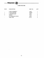
SLIDING DRAWER ELECTRICAL WIRING
PARTS LIST
ITEM
DESCRIPTION
PART NO.
QTY.
26
27
28
29
30
31
32
33
34
35
36
37
38
39
40
41
42
43
INTERLOCK SWITCH
POWER HARNESS
CONTROLLER COVER
DECAL "CAUTION"
DECAL SERVICE PROGRAM
CLAMP 3/8
CLAMP 5/8
INNERCONNECT HARNESS
HARNESS COIN MECHANISM
FUSE ASSEMBLY
FUSE MOUNTING BRACKET
CONTROLLER
HARNESS CONTROL BOARD
SCREW #6-20 X 3/16
SCREW #8-32 X 3/8
COIN CHUTE MOUNTING BRACKET
HARNESS CLAMP
WING NUT
19746
21532P
2330901
19819
21509
0853801
0853802
21538
2155101
17920
18060BLK
21513
21528
18370BLK
11894
21523BLK
0433201
19170
1
1
1
1
1
1
1
1
1
2
1
1
1
4
3
1
1
2
23
9
2
24
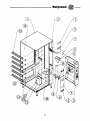
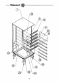
-----------h~ft~~~-MAIN CABINET ELECTRICAL WIRING
PARTS LIST
ITEM
DESCRIPTION
PART NO.
QTY
1
2
3
4
5
6
7
8
9
10
11
12
13
14
CABINETW/A
SLIDING DRAWER ASSEMBLY
POWER BOX ASSEMBLY
POWER BOX MOUNT
SCREW #8-18 X 3/8
POWER CORD ENTRANCE
STRAIN RELIEF BUSHING
HARNESS CLAMP
HARNESS CLAMP
TRAY MOTOR HARNESS 8 SEL.
TRAY MOTOR HARNESS 8 SEL.
LAMP ASSEMBLY HARNESS
PC BOARD TRAY HARNESS CONNECTOR
DRAWER ASSEMBLY POWER HARNESS
21428TDG
21507
21508
21478
01298BLK
23587
02438
0853802
0853801
2146501
2146501
21498
21528
21531
1
1
1
1
4
1
1
1
4
4
25
2
1
1
1
~
~ \ \_----..
\
\
IT
\
\
\_-....,.
\
\
\
\
8
\
\
\
o
0=0DO
=0DO
/
/
o
/
/
DO
<0
<0
<D
26A
SNACK TRAY ASSEMBLY
FIXED DIVIDERS
4-SELECTION
PARTS LIST
ITEM
1
2
3
4
5
6
7
8
9
10
11
12
13
DESCRIPTION
PART NO.
QTY
COMPLETE TRAY ASSEMBLY (DUAL HELIX)
21420
2141801
2145302
2145303
210-3010B
21365
17537
2146301
210-8021
01298BLK
01715
02614BLK
21438
18880
1
1
1
8
4
8
1
4
3
1
1
2
1.312"
TRAYWIA
TILT BRACKET L.H.
TILT BRACKET R.H.
WEAR PLATE
MOTOR
HUB COUPLING
TRAY HARNESS 4-SEL.
CANOE CLIP
SCREW #8-18 X 3/8
SCREW #8-32 X 3/8
SCREW #8-18 X 1/2
TILT OUT BRACKET PAD
ADHESIVE PAD
27
SNACK TRAY ASSEMBLY
REMOVABLE DIVIDERS
4-SELECTION
PARTS LIST
NOTE: NEW STYLE TRAYS INSTALLED IN ALL MACHINES
STARTING WITH SERIAL #1811 & HIGHER.
ITEM
DESCRIPTION
PART NO.
QTY
1
2
3
4
5
6
7
8
9
10
12
13
14
COMPLETE TRAY ASSEMBLY (DUAL HELIX) 2415516
23995
TRAYW/A
24128LH
TILT BRACKET L.H.
24128RH
TILT BRACKET R.H.
24000
DIVIDER ASSEMBLY
*MOTOR (DUAL HELIX)
23216
2404201
MOLDING, PRICE LABEL
2146301
TRAY HARNESS 4-SEL.
210-8021
CANOE CLIP
01298BLK
SCREW #8-18 X 3/8
01715
SCREW #8-32 X 3/8
21438
TILT OUT BRACKET PAD
18880
ADHESIVE PAD
24002
STANDOFF-PURSE LOCK
1
1
1
3
4
1
1
4
4
1
2
1.312"
3
* FOR LARGE SINGLE HELIX, USE MOTOR PART NO. 23894
27A
-_._-------~
28
-----4~
/
/
/
/
CD
CD
28A
CANDY TRAY ASSEMBLY
FIXED DIVIDERS
8-SELECTION
PARTS LIST
ITEM
1
2
3
4
5
6
7
8
9
10
11
12
13
DESCRIPTION
PART NO.
QTY
COMPLETE TRAY ASSEMBLY
2142006
2141805
2145302
2145303
210-30108
18365-3CC
17537
21527P
210-8021
01298BLK
01715
02614BLK
21438
18880
1
1
1
8
8
8
1
4
3
1
1
2
1.312"
TRAYWIA
TILT OUT BRACKET L.H.
TILT OUT BRACKET R.H.
WEAR PLATE
MOTOR
HlTB COUPLING
TRAY HARNESS 8 SEL.
CANOE CLIP
SCREW #8-18 X 3/8
SCREW #8-32 X 3/8 PH
SCREW #8-18 X 1/2
TILT OUT BRACKET PAD
ADHESIVE PAD
29
------------D~'-~~~-CANDY TRAY ASSEMBLY
REMOVABLE DIVIDERS
8-SELECTION
PARTS LIST
NOTE: NEW STYLE TRAYS INSTALLED IN ALL MACHINES
STARTING WITH SERIAL #1811 & HIGHER.
ITEM
DESCRIPTION
PART NO.
QTY
1
2
3
4
5
6
7
8
9
10
12
13
14
COMPLETE TRAY ASSEMBLY
TRAYW/A
TILT OUT BRACKET L.H.
TILT OUT BRACKET R.H.
DIVIDER ASSY.
MOTOR (SINGLE HELIX)
MOLDING, PRICE LABEL
TRAY HARNESS 8-SEL.
CANOE CLIP
SCREW #8-18 X 3/8
SCREW #8-32 X 3/8 PH
TILT OUT BRACKET PAD
ADHESIVE PAD
STANDOFF-PURSE LOCK
2415517
23995
24128LH
24128RH
24000
23894
2404201
21527P
210-8021
01298BLK
01715
21438
18880
24002
1
1
1
7
8
1
1
4
4
1
2
1.312"
3
29A
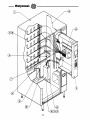
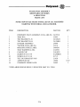
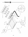
MAIN CABINET ASSEMBLY
PARTS LIST
TO BE USED IN CONJUNCTION WITH PAGES 31 AND 32
ITEM
DESCRIPTION
PART NO.
QTY
1
2
3
4
5
6
7
8
9
10
11
llA
lIB
12
13
14
15
16
17
18
19
20
21
22
23
24
25
26
27
28
29
30
31
CABINETWIA
21408TOM
21507
21515
2315103
17917BLK
17916
21518
17868BLK
17866BLK
17865BLK
17823
20132
20656
2307101
2346801
2337102
21512
23867BLK
17964
01298BLK
2158401
2142101
210-8012
23868BLK
2337103
2307701
19765
19302
21470
00729
22512DG
233002
17996BLK
1
1
1
1
2
1
1
1
1
1
1
1
1
1
6
6
1
1
1
16
6
6
12
1
6
4
4
16
1
2
1
1
3
DRAWER ASSEMBLY TOM'S SLIDING
UPPER ESCUTCHEON PLATE TOM'S
LOWER ESCUTCHEON PLATE TOM'S
END CAP ESCUTCHEON
MID ESCUTCHEON CAP
TOM'S DECAL
COIN RETURN TRIM
COIN RETURN CUP BLACK
COIN CUP DOOR
COIN HOPPER
COIN HOPPER LOCKING PLATE
COIN HOPPER SHUTE (NOT SHOWN)
COIN BANK
RIGHT HAND RAIL BLACK
R.H. TRAY SUPPORT STIFFENER
REAR DOOR COVER PLATE
R.H. PRODUCT DEFLECTOR
DRAWER SLIDE
SCREW #8-8 X 3/8
L.H. RAIL BLACK
TRAY FRONT SUPPORT
CANOE CLIP
L.H. PRODUCT DEFLECTOR
L.H. TRAY SUPPORT STIFFENER
TAPERED LEGS, WIA
LEG LEVELER
BOLT 5/16-18 X 5/8
COIN BOX HANDLE
POP RIVET
COVER PLATE
INSULATION REAR
SERVICE DOOR LOCK PLATE (NOT SHOWN)
30
31
32
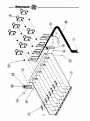
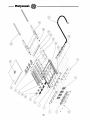
---------ItoI»\'lCnd:.c.~ HELIX ASSEMBLY
"USED WITH FIXED DIVIDER TRAY ASSEMBLIES"
OCKER
SNACK
Helix
Part No.
Product Thickness
10 ct
2208104
1 1/2"
8 ct
22081
1 7/8"
6 ct
1837406
2 1/2" (optional)
SEPARATE KICKER - 18303
CANDY
Product Thickness
Helix
Part No.
1"
2208001
14 ct
1 1/4"
12 ct
2208003
1 1/2"
2208002
10 ct
SEPARATE KICKER - 18302
HELIX ASSEMBLY
"USED WITH REMOVABLE TRAY ASSEMBLIES"
HUB
Helix
14 ct
10 ct
8 ct
6 ct
PASTRY
Part No.
Product Thickness
23978L3
1"
23978L2
1 1/2"
23978Ll
1 7/8"
23978L4
2 1/2"
SEPARATE KICKER - 18303
Helix
18 ct
14 ot "_
12 ct
10 ct
8 ct
HUB ASSEMBLY 23886
Helix
22 ct
14 ct
12 ct
10 ct
CANDY
Product Thickness
Part No.
5/8"
23977L6
1"
23977L4
1 1/4"
23977L3
1 1/2"
23977L2
SEPARATE KICKER - 210-3020B
HUB ASSEMBLY 23886
DUAL HELIX
Product Thickness
Part No. Left
Part No. Ri ht
1/2"
23977R5
23977L5
7/8"
23977R4
23977L4
1
tl
23977R3
23977L3
23977R2
23977L2
1 1/4"
23977Rl
23977Ll
1 1/2"
SEPARATE KICKER - 210-3020B HtTB ASSEMBLY 23886
33
, ........... ... .. .. . ... ...
, ..... ...... ... ......... ...
, ...... .. ... ...
, ... .... ...... .. ..
.. .. .. ...
.. ..
,' ...... ... ... .. .. ... .. ..
, .... ...... ... .. .. .. ..
, ........ .... .. ...
, .... ... .... ... ..
... ..
....
,' .. ....... .. ..
, ..... ....
, ..... ..... .. .... .. ...
, ..... .. .. .. ....
, .... .. .. .... .. ...
...
......
,, ........ ....
......
-.. , ...............
............ ....
'.....
'lilt ...
............. ' ...
... ...
... ...
.. . ..
.. ... .. .. .. ...
...
.. .... ......
.. .. .... .. .. ..
..
.. .. ..... ... ...
..
.. .... . .. .. ..
.. .. ... ... .. ...
..
.. .. .. .. .. ...
..
...... .. .. ....
.. ..... .. . ...
.. .. .. .. ... ......
.. .. .. .. .. ... ..
.. .. .. ... .. ....
.. .. ... ... .. .....
.. .... . .. ..
...
... .....
.. '
...
.. .. ......
...
, , .....
....
........
34
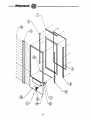
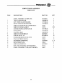
SERVICE DOOR ASSEMBLY
PARTS LIST
ITEM
DESCRIPTION
PART NO.
QTY
1
2
3
4
5
6
7
8
9
10
11
12
13
14
15
16
17
DOOR ASSEMBLY COMPLETE
TOP GLASS HOLDER
LEFT SIDE GLASS HOLDER
RIGHT SIDE GLASS HOLDER
SERVICE DOOR GLASS (TEMPERED)
SERVICE DOOR GASKET
LARGE HANDLE DOOR LOCK
CAM-LOCK
LOCKING BAR
SERVICE DOOR HINGE
SCREW #8-8 X 3/8
CARRIAGE BOLT #10.. 24 X 3/4
STAR LOCKNUT #10-24
NEOPRENE STRIPPING
RETAINING PLUG
SERVICE DOOR W/A
ROLL PIN T-HANDLE (NOT SHOWN)
DOOR STOP WIRE TYPE (NOT SHOWN)
21405DG
18499BLK
17954BLK
17954BLK
18761
17970
19379BLK
17457BLK
18001BLK
22030DG
01298BLK
15249
19566
18244500
18442
21406DG
19171
18907
1
1
1
1
1
12.6'
1
1
1
1
35
2
2
2.33'
1
1
1
1
35
,
36
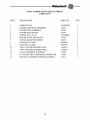
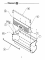
PRODUCT DELIVERY COMPARTMENT
PARTS LIST
ITEM
DESCRIPTION
1
2
DELIVERY COMPARTMENT ASSEMBLY
18492
DOOR ASSEMBLY DELIVERY COMPARTMENT 19987E
WASHER 1/4" NYLON
18684
DELIVERY DOOR RETAINER
18672BLK
PRODUCT DEFLECTOR
20126MBK
SCREW #8-18 X 3/8
01298BLK
BRACKET ANTI-THEFT
2322901
SCREW PANHEAD
13140
BRACKET ANTI-THEFT LEFT SIDE
23838LHB
BRACKET ANTI-THEFT RIGHT SIDE
23838RHB
POP RIVET
00729
ANTI-VANDAL KIT
23245
3
4
5
6
7
8
9
10
11
PART NO.
37
QTY
1
1
2
1
1
2
1
4
1
1
6
\
/
/
/
If)
(J)
38
NEW STYLE GUM AND MINT ASSEMBLY
R-32/ULTRA VENDOR-32
PARTS LIST
NOTE: New style gum and mint assembly installed in machines with serial number 1811
and higher.
ITEM
1
2
3
4
5
6
7
8
9
10
11
12
13
14
15
16
17
18
19
20
21
22
23
24
25
26
27
28
-~
DESCRIPTION
PART NO.
QTY
GUM AND MINT ASSEMBLY COMPLETE
TRAYW/A
SLIDE SUPPORT W/A
MOTOR
CAM
ACTUATOR
GUIDE BLOCK
WINDOW
GATE
PIVOT
SPRING
PRODUCT PUSHER
SPRING CONSTANT FORCE
ROLLER
BRACKET - SPRING RETURN
COVER - MID SIZE
EDGE TRIM
PRODUCT GUIDE R.H.
PRODUCT GUIDE L.H.
HEIGHT ADJUSTER BRACKET (OPTIONAL)
SLIDE-UHMW EXTRUSION
HARNESS
STRAIN RELIEF
CANOE CLIP
DECAL ItCAUTION t'
LATCH
SCREW #8 - 18 X 3/8
STRIKE
SELECTION NUMBER LABEL
2395004
2392601
2398101
23894
23888
23889
23890
23891
23892
23893
23908
19075
19165
23953
23927
2398201
23911
2391202
2391203
19166
23914
21574
23945
19176
19174
24123
01298BLK
24124
24134
1
1
1
4
4
4
4
4
4
4
4
4
4
4
1
1
2
4
4
2
2
1
1
2
1
2
2
2
A.R.
39
o
o
40
POWER BOX ASSEMBLY
ITEM
DESCRIPTION
PART NO.
QTY
1
2
4
5
6
7
9
10
POWER BOX W/A
TRANSFORMER
BALLAST ASSEMBLY
FUSE HARNESS
CIRCUIT BREAKER 2Amp.
SCREW
SCREW
SCREW
21534
18283
23548
21533
223001
01868BLK
01715
08976
1
1
1
1
1
3
1
2
41
~h~H~~~---------~
LIGHT FIXTURE
ITEM
1
2
3
DESCRIPTION
PART NO.
LIGHT ASSEMBLY
LAMP HARNESS
LAMP BRACKET
SCREW
FLUORESCENT BULB
WIRE TIES
21502
22882P
22982
13261
18845
02121
42
QTY
1
1
1
2
1
2
43
Rl
>-RED
PI
24V
YELLO
~
r----Jl
WHITE
llV
BLACK
>--
120V
------J
1
2 2
~_---I
118 VAC
MCiTOR MA TRIX
(SEE DETAIL ·A")
~J~~~.~~~r;J
f
~r-CfJ ~.,~. ~ ~. ~ ~
2
;l
110 VAC mr
110 VAC COI+lOH
110 VAC ENABLE
1
-~~~~~~r~~
~ULSl:
TO P2
.iii
I
2
1
~ ~ I~ (~J ~ H~ I{~ G~
1"
5
VALIDA lOR
WITHOUT
ESCROW
6
~~~r-G;J~~iGJrG;J
-
SERIAL
VALIDA TOR
WITH
ESCROW
TO P2
-DETAIL
- -AmI'.
11 I'L '51
PP
I
IIT213T1T5T6T7T8TsI1011h2h31111
3~=--------11
~~T
9302
SERIES
CHANGER
II
-21.
~
i;;OC
7
~~,
I~
~
t
I
21IlET
I t~~l
Ii
.- llELECTION 1
I- llELECTJON I
1-~.2
POWER.lIt VAC
I--ISELECTJON~
I I
I
_._.,
L
121
8
PI
A
5
(8.9)
B
12.51
1
15,61
fl
(5.8)
c
o
(2,61
2
(6.81
7
(5,S)
(2,SI
3
16.91
8
(1.9)
E
11.2)
1
11,1)
9
11.111
'------:.,.,==-.-:c-:
...... ••_ t e.......... 'a.iioi..- AHKTED .f tHiU IE'.
. . JAIII . . . . CQMII_
~
18
pp
pp
~~
~
·-· 3
viJ.- 1
2
S
VEt-{) COUNTER
_
-,
~f--,,-12~va:=--
fl,I-----------,
. P3
~
~
P6
(1,5)
[~
~
L
PP
CASH CUMle-
~ITf-f----=-=----,.
PP -'2
~_
\IOC
12VDC
CASH
COUNTER
f--'
- .-...
~
~~
J-l
107361
~-I
1,.
~
L..._ _---'==
J!
~
CONTROLLER
KEYPAD
0
TO P2
PP
9
l~l'~~(2,11
~--------
"6
L£
~21V~
AC
~PP- -,~
1 - llELECI lElI'AD
~I--------.::~-l
P2 7
pp-:TI
-21V
~I------~~
5
.tf:::llATA
==A---:-------J8
II \~ I l~
TI-------~+
T
5
·9~rr.;~~-----_-161 P1
• ",Ii," 1t.1 lJllli FfJl
\HI~
lJrw
-y'i'"2!
_1""'21'&21'.'
_ 5 5 arn.E
PS
~
.
DATA IN
~:~: ~
12VDC
VEND
COUNTER
__. _ - - - - -
>--.-.--...--.--.-.----.----..-.------~-
__. _ . _.. -._._..- - - _
..-•.
_--_.
23349
PARPLLEL
VALIDA TOR
WITH
ESCROW