1
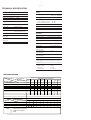
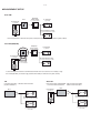
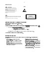
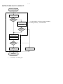
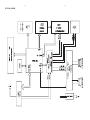
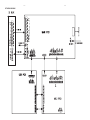
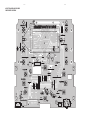
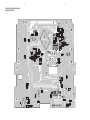
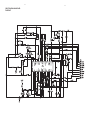
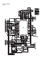
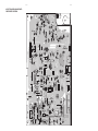
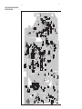
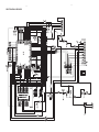
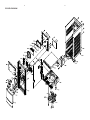
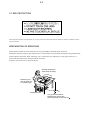
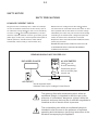
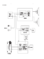
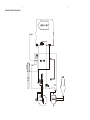
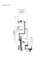
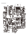
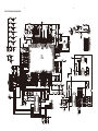
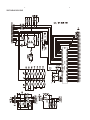
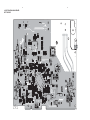
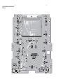
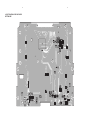
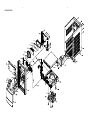
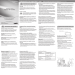
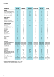
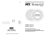
Micro Hi-Fi System
MCM166
-/12/55/05/77
This service manual is only for MCM166/12/55/05/77
This is previous generation models.
The serial number is:
before LM011039227020(only for/12)
before LM001039092086(only for /55/77)
CONTENTS
Technical specification ..................................................................1-2
Version variations .........................................................................1-2
Service measurement setup..........................................................1-3
Service aids .................................................................................1-4
Instructions on CD playability ................................................2-1..2-2
Disassembly diagram............ ........................................................3-1
Block diagram ................................................................................4-1
Wiring diagram ..............................................................................4-2
MCU board
Circuit diagram .........................................................................5-1
Layout diagram ..................................................................5-2..5-3
Main board
Circuit diagram ..................................................................6-1..6-3
Layout diagram ..................................................................6-4..6-5
USB board
Circuit diagram .........................................................................7-1
Layout diagram .........................................................................7-2
Exploded view diagram .................................................................8-1
© Copyright
2010 Philips Consumer Electronics B.V. Eindhoven, The Netherlands
All rights reserved. No part of this publication may be reproduced, stored in a retrieval
system or transmitted, in any form or by any means, electronic, mechanical, photocopying,
or otherwise without the prior permission of Philips.
Published by LX 1206 Service Audio
Version 1.4
Subject to modification
3141 785 33134
1-2
TECHNICAL SPECIFICATION
Tuner
Amplifier
Rated Output Power
Frequency Response
Signal to Noise Ratio
Aux Input
Tuning Range
2X5W RMS
60 - 16kHz, ±3dB
>65dB
0.5 V RMS 20kohm
Disc
Laser Type
Disc Diameter
Support Disc
Audio DAC
Total Harmonic
Distortion
Frequency
Response
S/N Ratio
Semiconductor
12cm/8cm
CD-DA, CD-R, CD-RW,
MP3-CD,WMA-CD
24Bits / 44.1kHz
<1%
Tuning grid
FM: 87.5 - 108MHz;
MW: 531 - 1602kHz
50KHz
Sensitivity
- Mono, 26dB S/N Ratio
- Stereo, 46dB S/N Ratio
Search Selectivity
Total Harmonic Distortion
Signal to Noise Ratio
<22 dBf
>43 dBf
>28dBf
<3%
>55dB
Speakers
Speaker Impedance 4ohm
Speaker Driver
3.5”woofer+0.8” tweeter
Sensitivity
>82dB/m/W
60Hz -16kHz (44.1kHz)
>65dBA
General information
AC power
Operation Power
Consumption
Standby Power
Consumption
Eco Standby Power
Consumption
USB Direct
Dimensions
- Main Unit (W x H x D)
- Speaker Box (W x H x D)
Weight
- With Packing
- Main Unit
- Speaker Box
220 - 230V, 50Hz
20W
<4W
<2W
Version 2.0/1.1
209 x231 x 147mm
146 x 228 x 160mm
6.6 kg
1.95 kg
2 x 1.2 kg
VERSION VARIATION
MCM166(for first generation)
Type /Versions:
/05
/12
/55
MCU BOARD
MAIN BOARD
C
C
C
C
C
C
USB BOARD
C
C
C
Board in used:
Service policy
Type /Versions:
Features
Feature diffrence
RDS
VOLTAGE SELECTOR
ECO STANDBY - DARK
* TIPS : C -- Component Lever Repair.
M -- Module Lever Repair
-- Used
/37
/ 61
/93
/98
/93
/98
MCM166(for first generation)
/05
/12
/55
/37
/61
1-3
MEASUREMENT SETUP
Tuner FM
DUT
RF Generator
Bandpass
250Hz-15kHz
LF Voltmeter
e.g. 7122 707 48001
e.g. PM2534
Ri=50:
e.g. PM5326
S/N and distortion meter
e.g. Sound Technology ST1700B
Use a bandpass filter to eliminate hum (50Hz, 100Hz) and disturbance from the pilottone (19kHz, 38kHz).
Tuner AM (MW,LW)
DUT
Bandpass
250Hz-15kHz
LF Voltmeter
e.g. 7122 707 48001
e.g. PM2534
RF Generator
e.g. PM5326
S/N and distortion meter
Ri=50:
e.g. Sound Technology ST1700B
Frame aerial
e.g. 7122 707 89001
To avoid atmospheric interference all AM-measurements have to be carried out in a Faraday´s cage.
Use a bandpass filter (or at least a high pass filter with 250Hz) to eliminate hum (50Hz, 100Hz).
Recorder
CD
Use Audio Signal Disc
(replaces test disc 3)
SBC429 4822 397 30184
Use Universal Test Cassette CrO2 SBC419 4822 397 30069
or Universal Test Cassette Fe
SBC420 4822 397 30071
LF Generator
DUT
e.g. PM5110
L
DUT
L
R
R
S/N and distortion meter
S/N and distortion mete
e.g. Sound Technology ST170
e.g. Sound Technology ST1700B
LEVEL METER
e.g. Sennheiser UPM550
with FF-filter
LEVEL METER
e.g. Sennheiser UPM550
with FF-filter
1-4
SERVICE AIDS
GB
ESD
WARNING
All ICs and many other semi-conductors are
susceptible to electrostatic discharges (ESD).
Careless handling during repair can reduce life
drastically.
When repairing, make sure that you are
connected with the same potential as the mass
of the set via a wrist wrap with resistance.
Keep components and tools also at this
potential.
GB
Safety regulations require that the set be restored to its original
condition and that parts which are identical with those specified,
be used
Safety components are marked by the symbol
Lead free
!
.
CLASS 1
LASER PRODUCT
2-1
INSTRUCTIONS ON CD PLAYABILITY
Customer complaint
"CD related problem"
Set remains closed!
check playability
1
playability
ok ?
N
Y
"fast" lens cleaning
3
For flap loaders (= access to CD drive possible)
cleaning method 4 is recommended
check playability
playability
ok ?
N
Y
Play a CD
for at least 10 minutes
check playability
playability
ok ?
N
Y
add Info for customer
"SET OK"
2
return set
1 - 4 For description - see following pages
Exchange CDM
2-2
INSTRUCTIONS ON CD PLAYABILITY
1
PLAYABILITY CHECK
4
LIQUID LENS CLEANING
For sets which are compatible with CD-RW discs
use CD-RW Printed Audio Disc ....................7104 099 96611
TR 3 (Fingerprint)
TR 8 (600µ Black dot) maximum at 01:00
• playback of these two tracks without audible disturbance
playing time for: Fingerprint 10seconds
Black dot from 00:50 to 01:10
• jump forward/backward (search) within a reasonable time
For all other sets
use CD-DA SBC 444A..................................4822 397 30245
TR 14 (600µ Black dot) maximum at 01:15
TR 19 (Fingerprint)
TR 10 (1000µ wedge)
• playback of all these tracks without audible disturbance
playing time for: 1000µ wedge 10seconds
Fingerprint 10seconds
Black dot from 01:05 to 01:25
• jump forward/backward (search) within a reasonable time
2
CUSTOMER INFORMATION
It is proposed to add an addendum sheet to the set which
informs the customer that the set has been checked
carefully - but no fault was found.
The problem was obviously caused by a scratched, dirty or
copy-protected CD. In case problems remain, the customer
is requested to contact the workshop directly.
The lens cleaning (method 3) should be mentioned in the
addendum sheet.
The final wording in national language as well as the printing
is under responsibility of the Regional Service Organizations.
Before touching the lens it is advised to clean the
surface of the lens by blowing clean air over it.
This to avoid that little particles make scratches on
the lens.
Because the material of the lens is synthetic and coated
with a special anti-reflectivity layer, cleaning must be done
with a non-aggressive cleaning fluid. It is advised to use
“Cleaning Solvent
The actuator is a very precise mechanical component and
may not be damaged in order to guarantee its full function.
Clean the lens gently (don’t press too hard) with a soft and
clean cotton bud moistened with the special lens cleaner.
The direction of cleaning must be in the way as indicated in
the picture below.
3-1
DISASSEMBLY DIAGRAM VIEW
3-1
4-1
SET BLOCK DIAGRAM
4-1
4-2
SET WIRING DIAGRAM
4- 2
5-1
CIRCUIT DIAGRAM - MCU BOARD
5-1
5-2
LAYOUT DIAGARM - MCU BOARD
COMPONENT SIDE VIEW
5-2
5-3
LAYOUT DIAGARM - MCU BOARD
COPPER SIDE VIEW
5-3
6-1
CIRCUIT DIAGRAM - MAIN BOARD
AF & AMP PART
6-1
6-2
CIRCUIT DIAGRAM - MAIN BOARD
TUNER PART
6-2
6-3
CIRCUIT DIAGRAM - MAIN BOARD
CD PART
6-3
6-4
LAYOUT DIAGARM - MAIN BOARD
COMPONENT SIDE VIEW
6-4
6-5
LAYOUT DIAGARM - MAIN BOARD
COPPER SIDE VIEW
6-5
7-1
CIRCUIT DIAGRAM - USB BOARD
7-1
7-2
LAYOUT DIAGRAM - USB BOARD
7-2
8-1
EXPLODED VIEW DIAGRAM
8-1
Micro Hi-Fi System
MCM166
-/12/55/ 77
This service manual is only for MCM166/12/55/77
This is 3rd generation models.
The serial number begins with:
LM011132315450 or LM021133318950(only for/12)
LM00113216591(only for /55)
LM1B1136014413(only for /77)
CONTENTS
Technical specification ..................................................................1-2
Version variations .........................................................................1-2
Service measurement setup..........................................................1-3
Service aids .................................................................................1-4
Instructions on CD playability ................................................2-1..2-2
Disassembly diagram............ ........................................................3-1
Block diagram ................................................................................4-1
Wiring diagram ..............................................................................4-2
MCU board
Circuit diagram .........................................................................5-1
Layout diagram ..................................................................5-2..5-3
Main board
Circuit diagram ..................................................................6-1..6-3
Layout diagram ..................................................................6-4..6-5
USB board
Circuit diagram .........................................................................7-1
Layout diagram .........................................................................7-2
Exploded view diagram .................................................................8-1
© Copyright
2010 Philips Consumer Electronics B.V. Eindhoven, The Netherlands
All rights reserved. No part of this publication may be reproduced, stored in a retrieval
system or transmitted, in any form or by any means, electronic, mechanical, photocopying,
or otherwise without the prior permission of Philips.
Published by LX 1206 Service Audio
Version 1.4
Subject to modification
3141 785 33134
1-2
TECHNICAL SPECIFICATION
Tuner
Amplifier
Rated Output Power
Frequency Response
Signal to Noise Ratio
Aux Input
Tuning Range
2X5W RMS
60 - 16kHz, ±3dB
>65dB
0.5 V RMS 20kohm
Disc
Laser Type
Disc Diameter
Support Disc
Audio DAC
Total Harmonic
Distortion
Frequency
Response
S/N Ratio
Semiconductor
12cm/8cm
CD-DA, CD-R, CD-RW,
MP3-CD,WMA-CD
24Bits / 44.1kHz
<1%
Tuning grid
FM: 87.5 - 108MHz;
MW: 531 - 1602kHz
50KHz
Sensitivity
- Mono, 26dB S/N Ratio
- Stereo, 46dB S/N Ratio
Search Selectivity
Total Harmonic Distortion
Signal to Noise Ratio
<22 dBf
>43 dBf
>28dBf
<3%
>55dB
Speakers
Speaker Impedance 4ohm
Speaker Driver
3.5”woofer+0.8” tweeter
Sensitivity
>82dB/m/W
60Hz -16kHz (44.1kHz)
>65dBA
General information
AC power
Operation Power
Consumption
Standby Power
Consumption
Eco Standby Power
Consumption
USB Direct
Dimensions
- Main Unit (W x H x D)
- Speaker Box (W x H x D)
Weight
- With Packing
- Main Unit
- Speaker Box
220 - 230V, 50Hz
20W
<4W
<2W
Version 2.0/1.1
209 x231 x 147mm
146 x 228 x 160mm
6.6 kg
1.95 kg
2 x 1.2 kg
VERSION VARIATION
MCM166( 3rd g eneration)
Type /Versions:
Board in used:
Service policy
/05
/12
/55
/37
/61
/93
/98
/93
/98
C
C
DISPLAY BOARD
MAIN BOARD
Type /Versions:
Features
Feature diffrence
RDS
VOLTAGE SELECTOR
ECO STANDBY - DARK
* TIPS : C -- Component Lever Repair.
M -- Module Lever Repair
-- Used
MCM166 ( 3rd g eneration)
/05
/12
/55
/37
/61
2-1
2.0 SAFTETY INSTRUCTIONS
GB
NL
ESD
WARNING
Alle IC’s en vele andere halfgeleiders zijn
gevoelig voor electrostatische ontladingen
(ESD).
Onzorgvuldig behandelen tijdens reparatie kan
de levensduur drastisch doen verminderen.
Zorg ervoor dat u tijdens reparatie via een
polsband met weerstand verbonden bent met
hetzelfde potentiaal als de massa van het
apparaat.
Houd componenten en hulpmiddelen ook op
ditzelfde potentiaal.
All ICs and many other semi-conductors are
susceptible to electrostatic discharges (ESD).
Careless handling during repair can reduce life
drastically.
When repairing, make sure that you are
connected with the same potential as the mass
of the set via a wrist wrap with resistance.
Keep components and tools also at this
potential.
F
ATTENTION
Tous les IC et beaucoup d’autres
semi-conducteurs sont sensibles aux
décharges statiques (ESD).
Leur longévité pourrait être considérablement
écourtée par le fait qu’aucune précaution n’est
prise à leur manipulation.
Lors de réparations, s’assurer de bien être relié
au même potentiel que la masse de l’appareil et
enfiler le bracelet serti d’une résistance de
sécurité.
Veiller à ce que les composants ainsi que les
outils que l’on utilise soient également à ce
potentiel.
WAARSCHUWING
D
I
WARNUNG
Alle ICs und viele andere Halbleiter sind
empfindlich gegenüber elektrostatischen
Entladungen (ESD).
Unsorgfältige Behandlung im Reparaturfall kan
die Lebensdauer drastisch reduzieren.
Veranlassen Sie, dass Sie im Reparaturfall über
ein Pulsarmband mit Widerstand verbunden
sind mit dem gleichen Potential wie die Masse
des Gerätes.
Bauteile und Hilfsmittel auch auf dieses gleiche
Potential halten.
AVVERTIMENTO
Tutti IC e parecchi semi-conduttori sono
sensibili alle scariche statiche (ESD).
La loro longevità potrebbe essere fortemente
ridatta in caso di non osservazione della più
grande cauzione alla loro manipolazione.
Durante le riparazioni occorre quindi essere
collegato allo stesso potenziale che quello della
massa dell’apparecchio tramite un braccialetto
a resistenza.
Assicurarsi che i componenti e anche gli utensili
con quali si lavora siano anche a questo
potenziale.
GB
Safety regulations require that the set be restored to its original
condition and that parts which are identical with those specified,
be used.
“Pour votre sécurité, ces documents
doivent être utilisés par des spécialistes agréés, seuls habilités à réparer
votre appareil en panne”.
NL
Veiligheidsbepalingen vereisen, dat het apparaat bij reparatie in
zijn oorspronkelijke toestand wordt teruggebracht en dat onderdelen,
identiek aan de gespecificeerde, worden toegepast.
CLASS 1
LASER PRODUCT
3122 110 03420
F
Les normes de sécurité exigent que l’appareil soit remis à l’état
d’origine et que soient utiliséés les piéces de rechange identiques
à celles spécifiées.
GB
Warning !
Invisible laser radiation when open.
Avoid direct exposure to beam.
D
Bei jeder Reparatur sind die geltenden Sicherheitsvorschriften zu
beachten. Der Original zustand des Geräts darf nicht verändert werden;
für Reparaturen sind Original-Ersatzteile zu verwenden.
I
Le norme di sicurezza esigono che l’apparecchio venga rimesso
nelle condizioni originali e che siano utilizzati i pezzi di ricambio
identici a quelli specificati.
"After servicing and before returning set to customer perform a
leakage current measurement test from all exposed metal parts to
earth ground to assure no shock hazard exist. The leakage current
must not exceed 0.5mA."
S
Varning !
Osynlig laserstrålning när apparaten är öppnad och spärren
är urkopplad. Betrakta ej strålen.
SF Varoitus !
Avatussa laitteessa ja suojalukituksen ohitettaessa olet alttiina
näkymättömälle laserisäteilylle. Älä katso säteeseen!
DK Advarse !
Usynlig laserstråling ved åbning når sikkerhedsafbrydere er
ude af funktion. Undgå udsaettelse for stråling.
Caution: These servicing instructions are for use by qualified service personnel only.
To reduce the risk of electric shock do not perform any servicing other than that contained in the operating instructions unless you are qualified to do so.
2-2
2.1 ESD PROTECTION
Whenthepowersupplyisbeingturnedon,youmaynotremovethislasercautionslabel.Ifitremoves,radiationoflaser
maybereceived.
PREPARATIONOFSERVICING
PickupHeadconsistsofalaserdiodethatisverysusceptibletoexternalstaticelectrocity.
Althoughitoperatesproperlyafterreplacement,ifitwassubjecttoelectrostaticdischargeduringreplacement,
itslifemightbeshortened.Whenreplacing,useaconductivemat,solderingironwithgroundwire,etc.to
protectthelaserdiodeformdamagebystaticelectricity.
Andalso,theLSIandICaresameasabove.
Groundconductive
wriststrapforbody.
Solderingiron
withgroundwire
orceramictype
1M
Conductivemat
Thegroundresistance
betweenthegroundline
andthegroundislessthan10
2-3
SAFTY NOTICE
SAFTY PRECAUTIONS
LEAKAGE CURRENT CHECK
Plug the AC line cord directly into a 120V AC outlet (do
Measure the AC voltage across the 1500
not use an isolation transformer for this check). Use an
AC voltmeter, having 5000 per volt or more sensitivity.
The test must be conducted with the AC switch on and
then repeated with the AC switch off. The AC voltage
Connect a 1500
indicated by the meter may not exceed 0.3V.A reading
10W resistor,paralleled by a 0.15uF
resistor.
150V AC capacitor between a knomn good earth ground
(water pipe, conduit, etc.) and all exposed metal parts of
exceeding 0.3V indicates that a dangerous potential
exists, the fault must be located and corrected.
cabinet (antennas, handle bracket, metal cabinet
screwheads, metal overlays, control shafts, etc.).
Repeat the above test with the DVD VIDEO PLAYER
power plug reversed.
NEVER RETURN A DVD VIDEO PLAYER TO THE
CUSTOMER WITHOUT TAKING NECESSARY
CORRECTIVE ACTION.
READING SHOULD NOT EXCEED 0.3V
AC VOLTMETER
DVD VIDEO PLAYER
(5000 per volt
or more sensitivity)
1500
10W
AC OUTLET
Good earth ground
such as a water pipe,
conduit, etc.
0.15uF 150V AC
Test all exposed metal.
Voltmeter Hook-up for Leakage Current Check
The lightning flash with arrowhead symbol, within an
equilateral triangle, is intended to alert the user to the
presence of uninsulated "dangerous voltage" within the
product's enclosure that may be of sufficient magnitude to
constitute a risk of electric shock to persons.
The exclamation point within an equilateral triangle is
intended to alert the user to the presence of important
operating and maintenance (servicing) instructions in the
literature accompanying the appliance.
3-1
BLOCK DIAGRAM
3-1
4-1
WIRING DIAGRAM FOR MCM166/12
4-1
4-1
WIRING DIAGRAM FOR MCM166/55/77
4-1
A
B
C
REAR CAB.
TOP CAB.
FRONT CAB.
E
D
6-1
CIRCUIT DIAGRAM - MAIN BOARD
6-1
6-2
CIRCUIT DIAGRAM - MAIN BOARD
6-2
6-3
CIRCUIT DIAGRAM - DISPLAY BOARD
6-3
6-4
LAYOUT DIAGRAM - MAIN BOARD
TOP SIDE
6-4
6-5
LAYOUT DIAGRAM - MAIN BOARD
BOTTOM SIDE
6-5
6-6
LAYOUT DIAGRAM - DISPLAY BOARD
TOP SIDE
6-6
6-7
LAYOUT DIAGRAM - DISPLAY BOARD
BOTTOM SIDE
6-7
7-1
EXPLODED VIEW
7-1