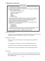
1
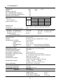
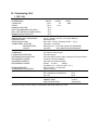
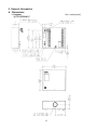
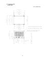
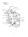
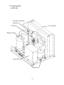
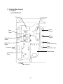
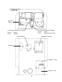
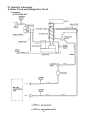
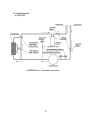
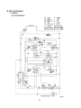
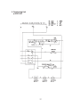
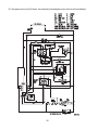
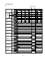
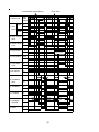
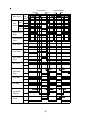
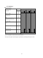
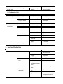
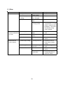
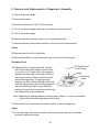
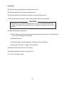
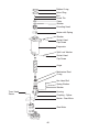
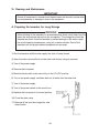
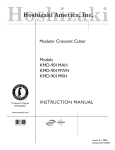
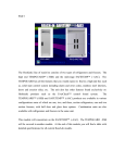
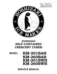
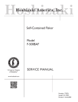
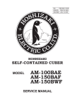
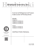
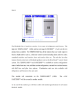
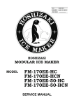
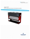
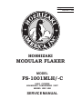
73122
NO:
ISSUED: September 12, 2005
HOSHIZAKI
MODULAR FLAKER
MODEL
FS-1001MLH/-C
ALSO COVERS
HOSHIZAKI CONDENSING UNIT
MODEL SRC-10H
SERVICE MANUAL
IMPORTANT
Only qualified service technicians should attempt to service or maintain this
icemaker. No such service or maintenance should be undertaken until the
technician has thoroughly read this Service Manual.
HOSHIZAKI provides this manual primarily to assist qualified service technicians in the
service and maintenance of the icemaker.
Should the reader have any questions or concerns which have not been satisfactorily
addressed, please call or write to the HOSHIZAKI Technical Support Department for
assistance.
HOSHIZAKI AMERICA, INC.
618 Highway 74 South
Peachtree City, GA 30269
Attn: HOSHIZAKI Technical Support Department
Phone: 1-800-233-1940 Technical Service
(770) 487-2331
Fax: 1-800-843-1056
(770) 487-3360
Web Site: www.hoshizakiamerica.com
NOTE: To expedite assistance, all correspondence/communication MUST include the
following information:
• Model Number
• Serial Number
• Complete and detailed explanation of the problem
2
Please review this manual. It should be read carefully before the icemaker is serviced or
maintenance operations are performed. Only qualified service technicians should service
and maintain the icemaker. This manual should be made available to the technician prior to
service or maintenance.
CONTENTS
I. Specifications .................................................................................................................... 5
A. Icemaker ...................................................................................................................... 5
1. FS-1001MLH .......................................................................................................... 5
2. FS-1001MLH-C ...................................................................................................... 6
B. Condensing Unit .......................................................................................................... 7
1. SRC-10H ................................................................................................................ 7
II. General Information .......................................................................................................... 8
A. Dimensions .................................................................................................................. 8
1. Icemaker ................................................................................................................. 8
a) FS-1001MLH/-C ................................................................................................ 8
2. Condensing Unit ..................................................................................................... 9
a) SRC-10H .......................................................................................................... 9
B. Construction ............................................................................................................... 10
1. Icemaker ............................................................................................................... 10
a) FS-1001MLH/-C .............................................................................................. 10
2. Condensing Unit ................................................................................................... 11
a) SRC-10H ........................................................................................................ 11
C. Control Box Layout .................................................................................................... 12
1. Icemaker ............................................................................................................... 12
a) FS-1001MLH/-C .............................................................................................. 12
2. Condensing Unit ................................................................................................... 13
a) SRC-10H ........................................................................................................ 13
III. Technical Information ..................................................................................................... 14
A. Water Circuit and Refrigeration Circuit ....................................................................... 14
1. Icemaker ............................................................................................................... 14
a) FS-1001MLH/-C .............................................................................................. 14
2. Condensing Unit ................................................................................................... 15
a) SRC-10H ........................................................................................................ 15
B. Wiring Diagram .......................................................................................................... 16
1. Icemaker ............................................................................................................... 16
a) FS-1001MLH/-C .............................................................................................. 16
2. Condensing Unit ................................................................................................... 17
a) SRC-10H ........................................................................................................ 17
C. Sequence of Electrical Circuit .................................................................................... 18
1. Icemaker ............................................................................................................... 18
D. Timing Chart .............................................................................................................. 27
E. Performance Data ...................................................................................................... 30
1. FS-1001MLH ........................................................................................................ 30
2. FS-1001MLH-C .................................................................................................... 31
3
IV. Service Diagnosis .......................................................................................................... 32
A. No Ice Production ...................................................................................................... 32
1. Icemaker ............................................................................................................... 32
2. Condensing Unit ................................................................................................... 34
B. Low Ice Production .................................................................................................... 34
C. Other .......................................................................................................................... 35
V. Removal and Replacement of Components ................................................................... 36
A. Service for Refrigerant Lines ...................................................................................... 36
1. Refrigerant Recovery ........................................................................................... 36
2. Evacuation and Recharge [R-404A] ..................................................................... 36
a) Complete ......................................................................................................... 36
b) Partial evacuation with pumpdown ................................................................. 37
B. Brazing ....................................................................................................................... 38
C. Service for Condensing Unit ...................................................................................... 39
1. Removal and Replacement of Compressor .......................................................... 39
2. Removal and Replacement of Condensing Pressure Regulator (C.P.R.) ............. 40
D. Removal and Replacement of Drier ........................................................................... 41
E. Removal and Replacement of Expansion Valve ........................................................ 42
F. Removal and Replacement of Evaporator Assembly ................................................. 43
G. Removal and Replacement of Control Water Valve ................................................... 47
H. Removal and Replacement of Flush Water Valve ...................................................... 48
VI. Cleaning and Maintenance ........................................................................................... 49
A. Preparing the Icemaker for Long Storage ................................................................... 49
B. Cleaning and Sanitizing Instructions .......................................................................... 50
1. Cleaning Solution ................................................................................................. 50
2. Cleaning Procedure ............................................................................................. 50
3. Sanitizing Solution ............................................................................................... 52
4. Sanitizing Procedure - Initial ................................................................................. 52
5. Sanitizing Procedure - Final ................................................................................. 53
C. Maintenance Instructions ........................................................................................... 55
4
I. Specifications
A. Icemaker
1. FS-1001MLH
No Data Available
We reserve the right to make changes in specifications and design without prior notice.
5
2. FS-1001MLH-C
AC SUPPLY VOLTAGE
GEAR MOTOR
OTHER
MAXIMUM FUSE SIZE
MAX. HACR BREAKER (USA ONLY)
MAX. CIRC. BREAKER (CANADA ONLY)
MINIMUM CIRCUIT AMPACITY
APPROXIMATE ICE PRODUCTION
PER 24 HR.
lbs./day ( kg/day )
Reference without *marks
SHAPE OF ICE
ICE QUALITY
APPROXIMATE STORAGE CAPACITY
ELECTRIC & WATER CONSUMPTION
ELECTRIC W (kWH/100 lbs.)
ELECTRIC W (kWH/100 lbs.)
POTABLE WATER
gal./24HR (gal./100 lbs.)
EXTERIOR DIMENSIONS (WxDxH)
EXTERIOR FINISH
WEIGHT
CONNECTIONS - ELECTRIC
- WATER SUPPLY
- DRAIN
- REFRIGERATION
CIRCUIT
ICE MAKING SYSTEM
HARVESTING SYSTEM
ICE MAKING WATER CONTROL
COOLING WATER CONTROL
BIN CONTROL SYSTEM (Primary)
BIN CONTROL SYSTEM (Secondary)
CONDENSING UNIT
EVAPORATOR
REFRIGERANT CONTROL
REFRIGERANT CHARGE
DESIGN PRESSURE
P.C. BOARD CIRCUIT PROTECTION
GEAR MOTOR PROTECTION
LOW WATER PROTECTION
ACCESSORIES -SUPPLIED
-REQUIRED
OPERATING CONDITIONS
115/60/1
120 V
3 FLA
1/4 HP
120 V
0.03A
15 A
15 A
15 A
15 A
Ambient
WATER TEMP. (°F)
Temp.(°F)
50
70
90
70
*830 (380)
805 (365)
785 (355)
80
765 (350)
750 (340)
730 (330)
90
710 (325)
*705 (320)
680 (310)
100
660 (300)
650 (295)
*600 (275)
Cubelet
Approx. 80%, Ice (90/70°F, Conductivity 200 µs/cm)
N/A
90/70°F
70/50°F
1745 (5.96)
1713 (4.94) FS-1001MLH-C & SRC-10H
FS-1001MLH-C ONLY
331 (1.13)
345 (1.00)
84 (12)
100 (12)
30" x 11" x 26" (766 x 279 x 660mm)
Stainless Steel
Net 126 lbs. ( 57 kg ), Shipping 166 lbs. ( 75 kg )
Cord Connection
Inlet 1/2" FPT
Outlet 3/4" FPT
Suction line 1-1/16-12 UNF Fitting (#10 AEROQUIP)
Liquid line
5/8-18 UNF Fitting (#6 AEROQUIP)
Auger type
Direct Driven Auger ( 1/4 HP Gear Motor )
Float Switch
N/A
Photoelctric Sensor
Mechanical Bin Control ( Proximity Sw. )
Air-cooled Remote Condensing unit SRC-10H Required
Copper Tube on Cylinder
Thermostatic Expansion Valve
Condensing Pressure Regulator on SRC-10H
R-404A,
8 lb.6oz.
(3800g)
(Ice Maker: 4 oz., Cond. Unit: 8 lb. 2 oz. )
High 427 PSIG, Low 230 PSIG
Fuse (1A)
Fuse (3A)
Float Switch and Timer
Spare Fuse
Ice Storage Bin
VOLTAGE RANGE
104-127 V
AMBIENT TEMP.
45-100° F
WATER SUPPLY TEMP.
45-90° F
WATER SUPPLY PRESSURE
10-113 PSIG
We reserve the right to make changes in specifications and design without prior notice.
6
B. Condensing Unit
1. SRC-10H
AC SUPPLY VOLTAGE
COMPRESSOR
FAN MOTOR
OTHER
MAXIMUM FUSE SIZE
MAX. HACR BREAKER (USA ONLY)
MAX. CIRC. BREAKER (CANADA ONLY)
MINIMUM CIRCUIT AMPACITY
EXTERIOR DIMENSIONS (WxDxH)
DIMENSIONS WITH LEGS (WxDxH)
EXTERIOR FINISH
WEIGHT (approximate)
CONNECTIONS - ELECTRIC
- REFRIGERATION
CIRCUIT
COMPRESSOR
CONDENSER
FAN MOTOR PROTECTION
REFRIGERATION PROTECTION
REFRIGERANT CONTROL
PUMPDOWN CONTROL
REFRIGERANT CHARGE
DESIGN PRESSURE
COMPRESSOR PROTECTION
ACCESSORIES -SUPPLIED
OPERATING CONDITIONS
208-230/60/1 (3 WIRE W/ NEUTRAL FOR 115V)
208-230
9.6 RLA
46 LRA
120 V
3A
MAX
120 V
0.5 A
20 A
20 A
20 A
20 A
28-1/4" x 23" x 19-7/8" (717 x 584 x 506mm)
30-1/4" x 25-3/8" x 34-7/8" (770 x 645 x 886mm)
Galvanized Steel
Net 143 lbs. ( 65 kg ), Shipping 169 lbs. ( 77 kg )
Permanent - Connection
Discharge line 1-1/16-12 UNF Fitting (#10 AEROQUIP)
Liquid line
5/8-18 UNF Fitting (#6 AEROQUIP)
Hermetic,
Model RS80-C2E-CAV
Air-cooled fin and tube type
Thermal Protector
Auto-reset High Pressure Switch, Manual low Pressure Switch
Condenser Pressure Regulator
Auto-reset Low Pressure Switch
R-404A,
8 lb.6oz.
(3800g)
(Ice Maker: 4 oz., Cond. Unit: 8 lb. 2 oz. )
High 427 PSIG, Low 230 PSIG
Internal Protector
Leg
2 pcs.
Hex. Head Bolt w/ Washer 8X16
8 pcs.
Hex. Nut
8 pcs.
VOLTAGE RANGE
187-253 V
AMBIENT TEMP.
-4-122° F
HEAT OF REJECTION
10500 BTU/hr
We reserve the right to make changes in specifications and design without prior notice.
7
II. General Information
A. Dimensions
Unit = inches [mm]
1. Icemaker
a) FS-1001MLH/-C
8
2. Condensing Unit
a) SRC-10H
Unit = [inches] mm
9
B. Construction
1. Icemaker
a) FS-1001MLH/-C
Water Supply
Inlet
Control Water
Valve
Bin Control
Power Supply
Cord
Control Box
Ice Chute
Evaporator
Expansion
Valve
Gear Motor
Beam Sensor
Drier
Flush Water
Valve
10
2. Condensing Unit
a) SRC-10H
Condenser Pressure
Regulator
Condenser
Fan Motor
Receiver Tank
Control Box
Compressor
11
C. Control Box Layout
1. Icemaker
a) FS-1001MLH/-C
Capacitor
Transformer
Flush
Switch
Cam
Timer
Power
Switch
Water Control
Relay
Fuse
(Timer Board 1A)
Gear Motor
Relay
Fuse
(Gear Motor 3A)
Connector
Timer Board
Time Delay
Relay
Connector
12
2. Condensing Unit
a) SRC-10H
Pressure
Switch
Low Pressure Switch 2 (Safety)
Cut-out
3 psig
Cut-in
6 psig (manual reset)
Low Pressure Switch 1 (Control)
Cut-out
9 psig
Cut-in
29 psig
Starter (Relay)
Magnetic Contactor
Capacitor
Capacitor - Start
Capacitor - Run
13
III. Technical Information
A. Water Circuit and Refrigeration Circuit
1. Icemaker
a) FS-1001MLH/-C
14
2. Condensing Unit
a) SRC-10H
15
B. Wiring Diagram
1. Icemaker
a) FS-1001MLH/-C
16
2. Condensing Unit
a) SRC-10H
17
C. Sequence of Electrical Circuit
1. Icemaker
1. When the power switch is moved to the “ON” position and the flush switch to the “ICE”
position, water starts to be supplied to the reservoir.
18
2. When the reservoir has been filled, the gear motor starts immediately.
19
3. The pumpdown solenoid valve energizes about 60 sec. after the gear motor starts.
!
20
4a. The bin control sensor operates and the pumpdown solenoid deenergizes after a
time delay set by the user. 60 seconds after that the gear motor stops.
21
4b. Should the bin control sensor fail and the bin control switch operate, the pumpdown
solenoid valve and gear motor will stop simultaneously 6 sec. after operation.
22
5. Low water.
23
6. When the flush switch is moved to the “FLUSH” position, the flush water valve opens and
flushes the reservoir and evaporator.
24
7. When the flush timer operates (for 15 min. every 12 hours).
25
8. If the gear motor fuse (3A) blows, the solenoid valve and gear motor will turn off immediately.
!
26
D. Timing Chart
Bin Control Switch
Off
On
1. Water Level
2. Float
Switch
Upper
Lower
Bottom
Upper On
Off
On
Lower Off
3. Water Control On
Off
Relay
4. Control Water On
Off
Valve
5. Flush Timer
1-2
2-3
6. Flush Switch
Flush
Ice
7. Flush Water
Valve
On
Off
8. Bin Control
On
Off
1 sec
9. Gear Motor
Relay
On
Off
10. Gear Motor
On
Off
11. Fan Motor
On
Off
6 sec
60 sec
12. Pumpdown
Solenoid
On
Off
13. Heater
On
Off
1 sec
60 sec
27
Low Water/Bin Control Sensor
1. Water Level
2. Float
Switch
Flush Timer
Upper
Lower
Bottom
Upper On
Off
On
Lower Off
3. Water Control On
Relay
Off
4. Control Water On
Off
Valve
5. Flush Timer
1-2
2-3
6. Flush Switch
Flush
Ice
7. Flush Water
Valve
On
Off
8. Bin Control
On
Off
21min every 12 hr
150 sec
9. Gear Motor
Relay
On
Off
10. Gear Motor
On
Off
11. Fan Motor
On
Off
90 sec
12. Pumpdown
Solenoid
On
Off
13. Heater
On
Off
1sec
150 sec
60 sec
28
90 sec
1sec
60
sec
Flush Switch
1. Water Level
2. Float
Switch
Pressure Switch
Off
On
Ice
Flush
Upper
Lower
Bottom
Upper On
Off
On
Lower Off
3. Water Control On
Off
Relay
4. Control Water On
Off
Valve
5. Flush Timer
1-2
2-3
6. Flush Switch
Flush
Ice
7. Flush Water
Valve
On
Off
8. Bin Control
On
Off
150 sec
9. Gear Motor
Relay
On
Off
10. Gear Motor
On
Off
11. Fan Motor
On
Off
1sec
90 sec
12. Pumpdown
Solenoid
60 sec
1sec
60 sec
On
Off
1sec
13. Heater
On
Off
29
E. Performance Data
1. FS-1001MLH
No Data Available
We reserve the right to make changes in specifications and design without prior notice.
30
2. FS-1001MLH-C
Performance Data:
APPROXIMATE
ICE PRODUCTION
PER 24 HR.
Ambient
Temp. (F)
70
80
90
lbs./DAY ( l/day)
100
APPROXIMATE ELECTRIC
70
CONSUMPTION
80
90
watts
100
APPROXIMATE WATER
70
CONSUMPTION PER 24 HR.
80
90
gal. / day (l/day)
100
EVAPORATOR OUTLET TEMP.
70
F ( C)
80
90
100
HEAD PRESSURE
70
80
90
PSIG (kg/sq.cmG)
100
SUCTION PRESSURE
70
PSIG (kg/sq.cmG)
80
90
100
HEAT OF REJECTION FROM BODY
Water Temp. (F)
70
90
803
365
784
356
378
347
747
340
729
331
324
*703
320
679
309
301
647
294
*600
273
-1717
-1722
--1731
-1736
--1745
-1760
--1789
-1804
-96
364
94
356
377
347
90
339
88
331
323
*84
319
81
308
301
78
293
*72
272
-10
14
-10
14
-10
-10
16
-9
16
-9
-9
*16
-9
18
-8
-8
18
-8
*18
-8
15.7
224
15.7
224
15.7
16.4
233
16.4
233
16.4
17.0
*242
17.0
242
17.0
19.6
279
19.6
*279
19.6
2.0
29
2.0
29
2.0
2.1
30
2.1
30
2.1
2.2
*31
2.2
31
2.2
2.3
33
2.3
*33
2.3
1130 BTU/hr AT 90 F/WT 70 F
50
*832
765
712
663
1713
1727
1740
1775
*100
92
85
80
*14
14
16
18
*224
233
242
279
*29
30
31
33
Note: The data without *marks should be used for reference.
We reserve the right to make changes in specifications and design without prior notice.
31
IV. Service Diagnosis
A. No Ice Production
1. Icemaker
Problem
Possible Cause
[1] The icemaker will not a) Power Supply
start.
1. OFF position.
Remedy
1. Move to ON position.
2. Loose connection.
2. Tighten.
3. Bad contacts.
3. Check for continuity and
replace.
4. Blown fuse.
1. Off position.
4. Replace.
1. Move to ON position.
2. Bad contacts.
2. Check for continuity and
replace.
c) Fuse (Control Box)
1. Blown out.
1. Check for short circuit and
replace.
d) Circuit Protect Relay
1. Miswiring.
1. Check power supply
voltage and wire properly.
e) Flush Timer
1. Flushing out.
2. Bad contacts.
1. Wait for 15 minutes.
2. Check for continuity and
replace.
f) Flush Switch
1. FLUSH position.
1. Move to ICE position.
2. Bad contacts.
2. Check for continuity and
replace.
g) Transformer
1. Coil winding opened.
1. Replace.
h) Control Water Valve
1. Coil winding opened.
1. Replace.
b) Power Switch
(Control Box)
i) Shut-off Valve
j) Plug and Receptacle
(Control Box)
k) Bin Control Sensor
[2] Water does not stop, a) Water Control Relay
and the icemaker will
not start.
b) Float Switch
c) Flush Water Valve
d) Hoses
1. Closed.
1. Open.
2. Water failure.
2. Wait until water is
supplied.
1. Disconnected.
1. Connect.
2. Terminal out of plug or 2. Insert terminal back in
receptacle.
position.
1. Failed sensor.
1. Check LED with power
switch on. Replace if
necessary.
2. Wet or scaled eye.
2. Wipe off and clean sensor
eye.
1. Contact fused.
1. Replace.
2. Coil winding opened.
2. Replace.
1. Bad contacts.
1. Check for continuity and
replace.
2. Clean or replace.
2. Float does not move
freely.
1. Valve seat clogged
and water leaking.
1. Disconnected.
32
1. Clean or replace.
1. Connect.
Problem
[3] Water has been
supplied, but the
icemaker will not
start.
Possible Cause
a) Water Control Relay
Remedy
1. Check for continuity and
replace.
1. Bad contacts.
b) Bin Control
1. Bad contacts.
1. Check for continuity and
replace.
2. Actuator does not
move freely.
2. Clean shaft and its
corresponding holes or
replace bin control.
3. Make sure that sensor 3. Clear/clean sensor eye.
eye is clear.
c) Gear Motor Relay
[4] Water has been
supplied, but gear
motor will not start
and solenoid will not
energize.
[5] Gear motor starts
and solenoid
energizes, but
machine does not
make ice or makes
ice intermittently.
1. Coil winding opened.
1. Replace.
2. Bad contacts.
2. Check for continuity and
replace.
1. Replace.
d) Control Timer
1. Broken.
(Printed Circuit Board)
a) Gear Motor Fuse
1. Blown fuse.
(BUSSMAN GMD
3.0A)
b) Thermal Protector
(Gear Motor)
1. Bad contacts.
1. Check for continuity and
replace.
a) High Pressure Switch
1. Dirty condenser.
1. Clean.
2. Ambient air
2. Need cooler conditions.
temperature at
condensing unit too
warm.
3. Refrigerant
3. Recharge.
overcharged.
4. Refrigerant line or
4. Clean and replace drier.
components plugged.
5. Bad contacts.
6. Loose connections.
[6] Gear motor starts,
but solenoid valve
will not energize or
energizes
intermittently.
1. See "C. [3]." Determine
the cause and replace the
fuse.
a) X2 Relay on Control
Timer
b) Solenoid Valve
[7] Gear motor starts
a) Refrigerant Line
and solenoid
energizes, but no ice
is produced.
5. Check for continuity and
replace.
6. Tighten.
1. Bad contacts.
1. Check for continuity and
replace.
2. Coil winding opened.
2. Replace timer.
1. Bad contacts.
2. Coil winding opened.
1. Check for continuity and
replace.
2. Replace coil.
3. Valve stuck closed.
3. Replace valve body.
1. Gas leaks.
1. Check for leaks with a
leak detector. Reweld
leak, replace drier and
charge with refrigerant.
The amount of refrigerant
is marked on nameplate or
label.
2. Replace clogged
component.
2. Refrigerant line
clogged.
33
Problem
[7] Continued from
previous page.
Possible Cause
b) Condensing Unit
1. Not functioning
properly.
Remedy
1. Proceed to "2.
Condensing Unit."
1. OFF position.
Remedy
1. Turn supply on.
2. Incorrect wiring.
2. Correct wiring.
2. Condensing Unit
Problem
Possible Cause
[8] Condensing unit does a) Power Supply
not start.
[9] Compressor will not
start or operates
intermittently.
b) Secondary Low
1. Awaiting reset.
Pressure Switch
c) Ice Machine
1. Ice machine off.
a) Low Pressure Switches 1. Faulty or
malfunctioning.
b) Magnetic Contactor
1. Coil winding opened.
c) Starter
1. Bad contacts.
1. Find cause and press
Reset button.
1. Turn on ice machine.
1. Check for continuity and
replace.
1. Replace.
1. Check for continuity and
replace.
2. Coil winding opened.
2. Replace.
3. Loose connections.
3. Tighten.
d) Start or Run Capacitor 1. Defective.
e) Compressor
1. Loose connections.
1. Replace.
1. Tighten.
2. Motor winding open or 2. Replace.
grounded.
3. Motor protector
3. Find cause of overcurrent
tripped.
or overheat.
f) Power Supply
1. Circuit Ampacity too
low.
1. Install larger conductor.
B. Low Ice Production
Problem
[1] Low ice production.
Possible Cause
a) Refrigerant Line
2. Refrigerant line
clogged.
Remedy
1. See "A. 1. [7] a)
Refrigerant Line."
2. Replace the clogged
component.
3. Overcharged.
3. Recharge.
1. Gas leaks.
b) High-side Pressure Too 1. Dirty condenser.
1. Clean.
High
2. Ambient air
2. Need cooler conditions.
temperature at
condensing unit too
warm.
3. Condensing unit out of 3. Check condensing unit.
order.
c) Expansion Valve (not
adjustable)
1. Low-side pressure too 1. Replace.
low.
2. Low-side pressure too 2. See if expansion valve
high.
bulb is mounted properly,
and replace the valve if
necessary.
34
C. Other
Problem
[1] Abnormal noise.
Possible Cause
a) Refrigerant Lines
b) Gear Motor (Ice
Making)
c) Evaporator
[2] Overflow from
a) Water Supply
reservoir (Water does
b) Control Water Valve
not stop.)
c) Float Switch
[3] Gear motor fuse
blown frequently.
1. Rub or touch lines or
other surfaces.
1. Bearing or gear worn
out / damaged.
c) Bin Control
1. Replace.
1. Too much pressure
1. Replace.
loss.
2. Scale on inside wall of 2. Remove auger. Use
freezing cylinder.
"SCALE AWAY" or "LIMEA-WAY" solution to clean
periodically. If the water is
found hard by testing,
install a softener.
1. Water pressure too
high.
1. Diaphragm does not
close.
1. Bad contacts.
a) Power Supply Voltage 1. Too high or too low.
b) Ice Making Unit
Remedy
1. Replace.
1. Bearings or auger
worn out.
1. Bad contacts.
2. Actuator does not
move freely.
35
1. Install a pressure reducing
valve.
1. Clean or replace.
1. Check for continuity and
replace.
1. Connect the unit to a
power supply of proper
voltage.
1. Replace bearings or
auger.
1. Check for continuity and
replace.
2. Clean shaft and its
corresponding holes or
replace bin control.
V. Removal and Replacement of Components
IMPORTANT
Ensure all components, fasteners and thumbscrews are securely in place
after the equipment is serviced.
IMPORTANT
1. The Polyolester (POE) oils used in R-404A units can absorb moisture
quickly. Therefore it is important to prevent moisture from entering the
system when replacing or servicing parts.
2. Always install a new filter drier every time the sealed refrigeration system
is opened.
3. Do not leave the system open for longer than 15 minutes when replacing
or servicing parts.
A. Service for Refrigerant Lines
1. Refrigerant Recovery
The icemaker unit is provided with two refrigerant service valves - one on the low-side
and one on the high-side line. Using proper refrigerant practices recover the refrigerant
from the service valves and store it in an approved container. Do not discharge the
refrigerant into the atmosphere.
2. Evacuation and Recharge [R-404A]
a) Complete
For complete evacuation of ice machine and condensing unit, follow the steps
below.
Note: For replacement of components inside the ice machine, a complete evacuation
is not necessary. For partial evacuation with pumpdown, see “Partial
evacuation with pumpdown” below.
1) Attach charging hoses, a service manifold and a vacuum pump to the system. Be
sure to connect charging hoses to both high-side and low-side service valves.
WARNING
Service valves have no valve core. Be sure valve stems are closed before
removing the flare caps to attach charging hoses.
IMPORTANT
The vacuum level and vacuum pump may be the same as those for current
refrigerants. However, the rubber hose and gauge manifold to be used for
evacuation and refrigerant charge should be exclusively for POE oils.
36
2) Turn on the vacuum pump. Never allow the oil in the vacuum pump to flow backwards.
3) Allow the vacuum pump to pull down to a 29.9" Hg vacuum. Evacuating period depends
on pump capacity.
4) Close the low-side valve and high-side valve on the service manifold.
5) Disconnect the vacuum pump and attach a refrigerant service cylinder to the high-side
line. Remember to loosen the connection and purge the air from the hose. See the rating
label on the control box in the icemaker for the required refrigerant charge. Hoshizaki
recommends only virgin refrigerant or reclaimed refrigerant which meets ARI Standard
No. 700-88 be used.
6) A liquid charge is recommended for charging an R-404A system. Invert the service
cylinder if necessary. Open the high-side, service manifold valve.
7) Allow the system to charge with liquid until the pressures balance.
8) If necessary, add any remaining charge to the system through the low-side. Use a
throttling valve or liquid dispensing device to add the remaining liquid chargethrough the
low-side access port with the unit running.
9) Close the two refrigerant service valves and disconnect the hoses and service
manifold.
WARNING
Service valves have no valve core. Be sure valve stems are closed before
disconnecting the hoses.
10) Cap the service valves to prevent a possible leak.
b) Partial evacuation with pumpdown
For replacement of components inside the ice machine, only a partial evacuation with
pumpdown is necessary.
1) If not already running, turn on the ice machine, making sure that the solenoid valve
energizes and that the bin control is not activated.
2) Turn off the power supply to the condensing unit.
3) In the condensing unit, close the liquid line shut-off valve by rotating the valve stem
clockwise until it is fully seated.
37
4) Turn the power supply to the condensing unit back on.
5) Once the automatic pumpdown cycle is complete and the condensing unit shuts itself
down, turn off the power supply to the condensing unit.
6) Close the suction line shut-off valve by rotating the valve stem clockwise until it is fully
seated.
7) See “1. Refrigerant Recovery” for instructions to recover remaining charge left in line sets
and ice machine.
8) When service is complete, evacuate line set and ice machine to 29.9” Hg vacuum.
9) Recharge ice machine and line set with 50g of R-404A refrigerant.
10) Close the two refrigerant service valves and disconnect the charging hoses, replacing
the flare caps on the service valves when finished.
WARNING
Service valves have no valve core. Be sure valve stems are closed before
disconnecting the hoses.
11) At the condensing unit, open both the liquid line and suction line shutoff valves.
12) Turn the power supply to the condensing unit back on.
B. Brazing
DANGER
1. Refrigerant R-404A itself is not flammable at atmospheric pressure and
temperatures up to 176° F.
2. Refrigerant R-404A itself is not explosive or poisonous. However, when
exposed to high temperatures (open flames) R-404A can be decomposed
to form hydrofluoric acid and carbonyl fluoride both of which are
hazardous.
3. Always recover the refrigerant and store it in an approved container. Do
not discharge the refrigerant into the atmosphere.
4. Do not use silver alloy or copper alloy containing arsenic.
5. Do not use R-404A as a mixture with pressurized air for leak testing.
Refrigerant leaks can be detected by charging the unit with a little
refrigerant, raising the pressure with nitrogen and using an electronic leak
detector.
38
C. Service for Condensing Unit
Note:
1. The condensing unit is wired independently from the icemaker. The compressor and
condenser fan motor energize when the suction line primary low pressure switch
closes. This switch has a cut-out point of 9 psig and a cut-in point of 29 psig.
Because of the independent wiring, the condensing unit may periodically energize
for short periods of time in order to keep suction pressures from building. This is
an automatic, continuous pumpdown and is perfectly normal for the machine.
2. A secondary low pressure switch exists in the suction line to ensure that the
machine will not be damaged should the primary switch fail. It has a cut-out point
of 3 psig and a differential of 6 psi. The switch is also equipped with a manual
reset, so that if it activates and shuts the condensing unit down it must be reset
after the cause of the failure has been found.
1. Removal and Replacement of Compressor
IMPORTANT
Always install a new drier every time the sealed refrigeration system is opened.
Do not replace the drier until after all other repair or replacements have been
made.
1) Turn off the power supply, and remove the panels.
2) Remove the terminal cover on the compressor and disconnect the compressor
wiring.
3) Recover the refrigerant and store it in an approved container, if required by an
applicable law.
4) Remove the discharge, suction and access pipes from the compressor using
brazing equipment.
WARNING
When repairing a refrigerant system, be careful not to let the burner flame
contact any electrical wires or insulation.
5) Remove the bolts and rubber grommets.
6) Slide and remove the compressor. Unpack the new compressor package. Install the new
compressor.
7) Attach the rubber grommets of the prior compressor.
39
8) Sandpaper the discharge, suction and access pipes.
9) Place the compressor in position and secure it using the bolts.
10) Remove plugs from the discharge, suction and access pipes.
11) Braze the access, suction and discharge lines (Do not change this order),
while purging with nitrogen gas flowing at a pressure of 3 - 4 psig.
12) Install the new drier in the icemaker.
13) Check for leaks using nitrogen gas (140 psig) and soap bubbles.
14) Evacuate the system, and charge it with refrigerant. See the rating label on the control
box in the icemaker for the required refrigerant charge and type.
15) Connect the terminals to the compressor, and replace the terminal cover in its correct
position.
16) Replace the panels in their correct positions, and turn on the power supply.
2. Removal and Replacement of Condensing Pressure Regulator (C.P.R.)
IMPORTANT
Always install a new drier every time the sealed refrigeration system is opened.
Do not replace the drier until after all other repairs or replacements have been
made.
1) Turn off the power supply to the condensing unit.
2) Remove the panels from the condensing unit.
3) See chapter V, section A. 2. a) and perform the complete evacuation procedure.
4) Recover the refrigerant and store it in an approved container.
5) Remove the C.P.R. using brazing equipment.
6) Braze the new C.P.R. with nitrogen gas flowing at a pressure of 3 - 4 psig.
WARNING
Always protect the C.P.R. body by using a damp cloth to prevent the C.P.R.
from overheating. Do not braze with the C.P.R. body exceeding 250°F.
40
7) Install the new drier in the icemaker.
8) Check for leaks using nitrogen gas (140 psig) and soap bubbles.
9) Evacuate the system. Charge
it with refrigerant. See the
rating label on the control box
in the icemaker.
10) Replace the panels in their
correct position.
11) Turn on the power supply
D. Removal and Replacement of Drier
IMPORTANT
Always install a new drier every time the sealed refrigeration system is opened.
Do not replace the drier until after all other repair or replacements have been
made.
1) Turn off the power supply, and remove the panels.
2) See chapter V, section A. 2. for evacuation procedure.
3) Recover the refrigerant and store it in an approved container, if required by applicable
law.
4) Remove the drier using brazing equipment.
5) Install the new drier with the arrow on the drier in the direction of the refrigerant flow. Use
nitrogen gas at a pressure of 3 - 4 psig when brazing the tubings.
6) Check for leaks using nitrogen gas (140 psig) and soap bubbles.
7) Evacuate the system, and charge it with refrigerant. See the rating label on the control
box in the icemaker for the required refrigerant charge and type.
8) Replace the panels in their correct position and turn on the power supply.
41
E. Removal and Replacement of Expansion Valve
IMPORTANT
Sometimes moisture in the refrigerant circuit exceeds the drier capacity and
freezes up at the expansion valve. Always install a new drier every time the
sealed refrigeration system is opened. Do not replace the drier until after all
other repairs or replacements have been made.
1) Turn off the power supply, and remove the panels.
2) See chapter V, section A. 2. for evacuation procedure.
3) Recover the refrigerant and store it in an approved container, if required by applicable
law.
4) Remove the expansion valve bulb at the evaporator outlet.
5) Remove the expansion valve cover and remove the expansion valve using brazing
equipment.
6) Braze the new expansion valve with nitrogen gas flowing at a pressure of 3 - 4 psig.
WARNING
Always protect the valve body by using a damp cloth to prevent the valve from
overheating. Do not braze with the valve body exceeding 250°F.
7) Install the new drier.
8) Check for leaks using nitrogen gas (140 psig) and soap bubbles.
9) Evacuate the system. Charge it with refrigerant. See the rating label on the control box in
the icemaker for the required refrigerant charge and type.
10) Attach the bulb to the suction line and make it level. Be sure to secure the bulb using a
band and to insulate it.
11) Place the new set of expansion valve covers in position.
12) Replace the panels in their correct position and turn on the power supply.
42
F. Removal and Replacement of Evaporator Assembly
1) Turn off the power supply.
2) Remove the panels.
3) Move the flush switch to the “FLUSH” position.
4) Turn on the power supply and drain out all water from the water line.
5) Turn off the power supply.
6) Remove the strap connecting the spout to the chute assembly.
7) Remove the three thumbscrews and take off the spout from the evaporator.
Cutter
8) Remove the bolt and lift off the cutter.
9) Remove the rubber O-ring and the nylon ring at the top of the evaporator.
Extruding Head
10) Replace the bolt in the auger shaft. Use the
bolt to move the auger towards you and then
try to insert a .02” round stock or pin gauge in
between the back side of the auger shaft and
the bearing surface. Check several locations
around the auger shaft. If the gauge goes
between the shaft and the bearing at any point,
both the top bearing in the extruding head and
the lower bearing in the housing should be
replaced. Instructions for removing the housing
are located later in this procedure.
.02” Round Stock
or Pin Gauge
Auger
Extruding
Head
Note: Replacing the bearing requires a bearing press adaptor. If one is not available,
replace the whole extruding head and housing.
11) Remove the four socket head cap screws and lift off the extruding head.
Auger
12) Lift off the auger. If the area in contact with the bearing is worn out or the blade
scratched, replace the auger.
43
Evaporator
Note: Skip the following steps 13) through 15) when the evaporator does not need
replacement.
13) See chapter V, section A. 2. b) and perform the partial evacuation procedure.
14) Recover the refrigerant and store it in an approved container, if required by an
applicable law.
IMPORTANT
Always install a new drier every time the sealed refrigeration system is opened.
Do not replace the drier until after all other repair or replacements have been
made.
15) Remove the bulb of the expansion valve.
16) Disconnect the brazing-connections of the expansion valve and the copper tube-low
side from the evaporator, using brazing equipment.
17) Remove the two truss head machine screws and the strap securing the
evaporator.
18) Disconnect the two hoses from the evaporator.
19) Remove the four socket head cap screws securing the evaporator to the housing.
20) Lift off the evaporator.
Housing, Lower Bearing and Mechanical Seal
21) The mechanical seal consists of two parts. One moves along with the auger, and the
other is fixed on the housing. If the contact surfaces of these two parts are worn
or scratched, the mechanical seal may cause water leaks and should be replaced.
22) Remove the O-ring from the housing.
23) Remove the six bolts and the housing from the gear motor. If inspection of the bearing
inside the extruding head (earlier in this procedure) indicated that it is out of tolerance,
replace both it and the bearing inside the housing.
Note: Replacing the bearing requires a bearing press adaptor. If one is not available,
replace the whole extruding head and housing.
44
Gear Motor
24) Remove the coupling-spline on the gear motor shaft.
25) Remove the barrier on the top of the gear motor.
26) Remove the three socket head cap screws securing the gear motor.
27) Assemble the removed parts in the reverse order of the above procedure.
WARNING
Be careful not to scratch the surface of the O-ring or it may cause water leaks.
Handle the mechanical seal with care not to scratch or contaminate its contact
surface.
28) When replacing the evaporator;
(a) Braze the new evaporator with nitrogen gas flowing at a pressure of 3 - 4 psig. Be careful
not to burn the evaporator insulation.
(b) Replace the drier.
(c) Check for leaks using nitrogen gas (140 psig) and soap bubbles.
(d) Evacuate the system. Charge it with refrigerant.
29) Move the flush switch to the “ICE” position.
30) Replace the panels in their correct position.
31) Turn on the power supply.
45
Rubber O-ring
Nylon Ring
Bolt
Dowel Pin
Cutter
Washer
Extruding Head
Heater with Spring
Washer
Socket Head
Cap Screw
Evaporator
Split Lock Washer
Socket Head
Cap Screw
Auger
Mechanical Seal
O-ring
Hex Head Bolt
Spring Washer
Washer
Housing
Truss Head
Screw
Coupling - Spline
Barrier - Gear Motor
Gear Motor
46
G. Removal and Replacement of Control Water Valve
1) Turn off the power supply, remove the panels and close the water supply line shut-off
valve.
2) Disconnect the terminals from the control water valve.
3) Loosen the fitting nut on the control water valve inlets and remove the control water valve.
Do not lose the packings inside the fitting nut.
4) Remove the water supply hose from the control water valve.
5) Install the new control water valve.
6) Assemble the removed parts in the reverse order of the above procedure.
7) Open the water supply line shut-off valve.
8) Check for water leaks.
9) Replace the panels in their correct position, then turn on the power supply.
47
H. Removal and Replacement of Flush Water Valve
1) Turn off the power supply, remove the panels and close the water supply line shut-off
valve.
2) Remove the clamp and disconnect the flush water valve.
Note: Water may still remain inside the evaporator. Be sure to drain the water into the
drain pan.
3) Disconnect the terminals from the flush water valve.
4) Remove the flush water valve from the bracket.
5) Remove the drain pipe from the flush water valve.
6) Connect the drain pipe to the new flush water valve and place the valve in position.
7) Connect the hose to the flush water valve and secure it with the clamp.
8) Pour water into the reservoir and check for water leaks on the flush water valve.
9) Open the water supply line shut-off valve, then turn on the power supply.
10) Move the flush switch to the “ICE” position.
11) Check for water leaks.
12) Move the flush switch to the “FLUSH” position and make sure water is flushing.
13) Move the flush switch to the “ICE” position.
14) Replace the panels in their correct position.
48
VI. Cleaning and Maintenance
IMPORTANT
Ensure all components, fasteners and thumbscrews are securely in place after
any maintenance or cleaning is done to the equipment.
A. Preparing the Icemaker for Long Storage
WARNING
When shutting off the icemaker for an extended time, drain out all water from the
water line and remove the ice from the storage bin. The storage bin should be
cleaned and dried. Drain the icemaker to prevent damage to the water supply
line at sub-freezing temperatures, using air or carbon dioxide. Shut off the
icemaker until the proper ambient temperature is resumed.
1) Run the icemaker with the water supply line shut-off valve closed.
2) Open the drain valve and blow out the water inlet line by using air pressure.
3) Turn off the power supply.
4) Remove the front panel.
5) Move the flush switch on the control box to the “FLUSH” position.
6) Turn on the power supply, and then drain out all water from the water line.
7) Turn off the power supply.
8) Turn off the power switch on the control box.
9) Replace the front panel in its correct position.
10) Close the drain valve.
11) Remove all ice from the storage bin, and
clean the bin.
49
B. Cleaning and Sanitizing Instructions
WARNING
1. HOSHIZAKI recommends cleaning this unit at least once a year. More
frequent cleaning, however, may be required in some existing water
conditions.
2. To prevent injury to individuals and damage to the icemaker, do not use
ammonia type cleaners.
3. Always wear liquid-proof gloves to prevent the cleaning and sanitizing
solutions from coming into contact with skin.
1. Cleaning Solution
Dilute 4.8 fl. oz. (142 ml) of recommended cleaner Hoshizaki “Scale Away” or
“LIME-A-WAY” (Economics Laboratory, Inc.) with 0.8 gallons (3 l) of warm water. This is a
minimum amount. Make more solution if necessary.
IMPORTANT
For safety and maximum effectiveness, use the solution immediately after
dilution.
2. Cleaning Procedure
The cleaning process will remove lime deposits from the water system.
1) Remove the front panel and top panel, then turn off the power supply.
2) Close the water supply line shut-off valve.
3) Remove all ice from the storage bin.
4) Move the flush switch to the “FLUSH” position.
5) Turn on the power supply and drain out all water from the water line.
6) Turn off the power supply.
7) Remove the control water valve by removing the fitting nut and two mounting screws. Do
not lose the packing.
8) Check the control water valve screen for debris and clean as necessary.
50
9) Replace the control water valve in its correct position.
10) Remove the strap connecting the spout to the chute assembly.
11) Remove the thumbscrews securing the spout and lift it off.
12) Pour the cleaning solution over the extruding head until the evaporator assembly and
the reservoir are filled and the solution starts to overflow into the drain pan.
Note: If there is excess scale on the extruding head, fill the evaporator assembly and
reservoir as described above, then use a clamp on the reservoir hose between the
reservoir and evaporator assembly to block flow. Pour additional cleaning fluid
over the extruding head until the evaporator assembly is completely full.
13) Replace the spout and strap in their correct positions.
14) Allow the icemaker to sit for about 10 minutes before operation. If you placed a clamp on
the reservoir hose in step 9, remove it before operation.
15) Move the flush switch to the “ICE” position, then turn on the power supply. Replace the
top panel and front panel in their correct positions. Make ice using the solution until the
icemaker stops making ice.
Note: Always discard the contaminated ice produced during this procedure.
16) Remove the front panel.
17) Move the flush switch to the “FLUSH” position to drain the remainder of the solution.
18) After the solution is drained, move the flush switch to the “ICE” position.
19) Replace the front panel in its correct position.
20) Open the water supply line shut-off valve and supply water to the reservoir.
21) When the gear motor starts, remove the front panel and turn off the power supply.
22) Drain out all water from the water line. See 4) through 6).
51
3. Sanitizing Solution
Dilute 2.5 fl. oz. (74 ml or 5 tbs) of IMS-II Sanitizer or a 5.25% sodium hypochlorite solution
(chlorine bleach) with 5 gallons (19 l) of warm water.
IMPORTANT
For safety and maximum effectiveness, use the solution immediately after
dilution.
4. Sanitizing Procedure - Initial
The sanitizing process will sanitize the icemaker.
1) Close the water supply line shut-off valve.
2) Remove the strap connecting the spout to the chute assembly.
3) Remove the thumbscrews securing the spout and lift it off. Remove the rubber O-ring and
nylon O-ring at the top of the cylinder and also remove the packing between the spout
and the chute.
4) Pour the sanitizing solution over the extruding head until the evaporator assembly and
the reservoir are filled and the solution starts to overflow into the drain pan.
5) Remove the two thumbscrews securing the proximity switch to the chute assembly.
6) Remove the chute assembly from the icemaker.
7) Remove the packing at the bottom of the ice chute.
8) Remove the three ties and the chute insulation.
9) Remove the six wing nuts and two baffles.
10) Remove the two thumbscrews, the plate and the packing from the top of the ice chute,
then remove the bin control assembly by sliding it slightly toward the chute opening and
lifting it off.
11) Disassemble the bin control assembly by removing the two snap pins, shaft and
actuator.
12) Soak the removed parts in .25 gallons (1 l) of sanitizing solution for 10 minutes then
wipe them down.
13) Rinse the parts thoroughly.
IMPORTANT
If the solution is left on these parts, they will rust.
52
14) Replace all parts in their correct positions.
IMPORTANT
When installing the baffles, make sure that the bent surface (the one without the
studs) faces the actuator so that the bent surface can guide the ice to the center
of the actuator.
15) Move the flush switch to the “ICE” position, then turn on the power supply. Replace the
top panel and front panel in their correct positions. Make ice using the solution until the
icemaker stops making ice.
Note: Always discard the contaminated ice produced during this procedure.
5. Sanitizing Procedure - Final
1) Remove the front panel and top panel, then turn off the power supply.
2) Move the flush switch to the “FLUSH” position.
3) Turn on the power supply and drain out all water from the water line.
4) Turn off the power supply.
5) Remove the strap connecting the spout to the chute assembly.
6) Remove the thumbscrews securing the spout and lift it off.
7) Pour the sanitizing solution over the extruding head until the evaporator assembly and
the reservoir are filled and the solution starts to overflow into the drain pan.
8) Replace the spout and strap in their correct positions.
9) Allow the icemaker to sit for about 10 minutes before operation.
10) Move the flush switch to the “ICE” position, then turn on the power supply. Replace the
top panel and front panel in their correct positions. Make ice using the solution until the
icemaker stops making ice.
Note: Always discard the contaminated ice produced during this procedure.
11) Remove the front panel.
12) Move the flush switch to the “FLUSH” position to drain the remainder of the solution.
13) After the solution is drained, move the flush switch to the “ICE” position.
14) Replace the front panel in its correct position.
15) Open the water supply line shut-off valve and supply water to the reservoir.
53
16) When the gear motor starts, remove the front panel and turn off the power supply.
17) Drain out all water from the water line. See 2) and 3).
18) Move the flush switch to the “ICE” position and run the icemaker.
19) Turn off the power supply after 30 minutes.
20) Pour warm water into the storage bin to melt all ice, and then clean the bin liner with the
solution.
21) Flush out any solution from the storage bin.
22) Turn on the power supply and start the automatic icemaking process.
IMPORTANT
1. After cleaning, do not use ice made from the sanitizing solution. Be careful
not to leave any solution in the storage bin.
2. Follow carefully any instructions provided with the bottles of cleaning or
sanitizing solution.
3. Never run the icemaker when the reservoir is empty.
54
C. Maintenance Instructions
IMPORTANT
1. This icemaker must be maintained individually, referring to the instruction
manual and labels provided with the icemaker.
2. To achieve optimum icemaker performance, the following parts need periodic
inspection and maintenance:
Extruding Head and Upper Bearing
Housing and Lower Bearing
Evaporator Cylinder
Auger
Gear Motor
Mechanical Seal
These parts should be inspected at least once a year or every 10,000
hours of operation. Their service life, however, depends on water quality
and environment. More frequent inspection and maintenance are
recommended in bad or severe water conditions.
Replacement of the following consumable parts is recommended if wear
exceeds factory recommendations:
Upper Bearing
Lower Bearing
Mechanical Seal
Consult with your local distributor about inspection and maintenance service.
To obtain the name and phone number of your local distributor, call
Hoshizaki Technical Support at 1-800-233-1940 in the USA.
1) Stainless Steel Exterior
To prevent corrosion, wipe the exterior occasionally with a clean and soft cloth. Use a
damp cloth containing a neutral cleaner to wipe off oil or dirt build up.
2) Storage Bin and Scoop
• Wash your hands before removing ice. Use the plastic scoop provided (bin
accessory).
• The storage bin is for ice use only. Do not store anything else in the bin.
• Keep the scoop clean. Clean using a neutral cleaner and rinse thoroughly.
• Clean the bin liner using a neutral cleaner. Rinse thoroughly after cleaning.
3) Condenser
Check the condenser once a year, and clean the coil if required by using a brush or
vacuum cleaner. More frequent cleaning may be required depending on the location
of the condensing unit.
55