1
Plasma Arc
Cutting System
Service Manual
804470 Revision 2
AMPS
60
40
30
80
100
AC
50
60
4.0
V
PSI
70
80
5.0
6.0
BAR
_
+
G3 S
E R IE
S
™
Service Manual
(P/N 804470)
Revision 2 June, 2003
Hypertherm, Inc.
Hanover, NH USA
www.hypertherm.com
© Copyright 2003 Hypertherm, Inc.
All Rights Reserved
Hypertherm and Powermax are trademarks of Hypertherm, Inc.
and may be registered in the United States and/or other countries.
Hypertherm, Inc.
Etna Road, P.O. Box 5010
Hanover, NH 03755 USA
603-643-3441 Tel (Main Office)
603-643-5352 Fax (All Departments)
[email protected] (Main Office Email)
800-643-9878 Tel (Technical Service)
[email protected] (Technical Service Email)
800-737-2978 Tel (Customer Service)
[email protected] (Customer Service Email)
Hypertherm Automation, LLC
5 Technology Drive, Suite 300
West Lebanon, NH 03755 USA
603-298-7970 Tel
603-298-7977 Fax
Hypertherm Plasmatechnik, GmbH
Technologiepark Hanau
Rodenbacher Chaussee 6
63457 Hanau-Wolfgang, Deutschland
49 6181 58 2100 Tel
49 6181 58 2134 Fax
49 6181 58 2123 (Technical Service)
Hypertherm (S) Pte Ltd.
No. 19 Kaki Bukit Road 2
K.B. Warehouse Complex
Singapore 417847, Republic of Singapore
65 6 841 2489 Tel
65 6 841 2490 Fax
65 6 841 2489 (Technical Service)
Hypertherm UK, Ltd.
9 Berkeley Court, Manor Park
Runcorn, Cheshire, England WA7 1TQ
44 1928 579 074 Tel
44 1928 579 604 Fax
France
15 Impasse des Rosiers
95610 Eragny, France
00 800 3324 9737 Tel
00 800 4973 7329 Fax
Hypertherm S.r.l.
Via Torino 2
20123 Milano, Italia
39 02 725 46 312 Tel
39 02 725 46 400 Fax
39 02 725 46 314 (Technical Service)
Hypertherm Europe B.V.
Vaartveld 9
4704 SE Roosendaal, Nederland
31 165 596907 Tel
31 165 596901 Fax
31 165 596908 Tel (Marketing)
31 165 596900 Tel (ETSO – Technical Service)
00 800 49 73 7843 Tel (ETSO – Technical Service
toll-free in Europe)
Japan
1952-14 Yata-Natsumegi
Mishima City, Shizuoka Pref.
411-0801 Japan
81 0 559 75 7387 Tel
81 0 559 75 7376 Fax
5/23/03
Hypertherm Brasil Ltda.
Rua Visconde de Santa Isabel, 20 – Sala 611
Vila Isabel, RJ
Brasil CEP 20560-120
55 21 2278 6162 Tel
55 21 2578 0947 Fax
ELECTROMAGNETIC COMPATIBILITY (EMC)
EMC INTRODUCTION
Hypertherm's CE-marked equipment is built
in compliance with standard EN50199. The
equipment should be installed and used in
accordance with the information below to
achieve electromagnetic compatibility.
The limits required by EN50199 may not be
adequate to completely eliminate interference when the affected equipment is in
close proximity or has a high degree of
sensitivity. In such cases it may be necessary to use other measures to further
reduce interference.
This plasma equipment is designed for use
only in an industrial environment.
INSTALLATION AND USE
The user is responsible for installing and
using the plasma equipment according to
the manufacturer's instructions. If electromagnetic disturbances are detected then it
shall be the responsibility of the user to resolve the situation with the technical assistance of the manufacturer. In some cases
this remedial action may be as simple as
earthing the cutting circuit, see Earthing of
Workpiece. In other cases it could involve
constructing an electromagnetic screen
enclosing the power source and the work
complete with associated input filters. In all
cases electromagnetic disturbances must
be reduced to the point where they are no
longer troublesome.
ASSESSMENT OF AREA
Before installing the equipment the user
shall make an assessment of potential electromagnetic problems in the surrounding
area. The following shall be taken into
account:
a. Other supply cables, control cables,
signalling and telephone cables; above,
below and adjacent to the cutting equipment.
b. Radio and television transmitters and
receivers.
c. Computer and other control equipment.
d. Safety critical equipment, for example
guarding of industrial equipment.
e. Health of the people around, for
example the use of pacemakers and hearing aids.
f. Equipment used for calibration or measurement.
g. Immunity of other equipment in the environment. User shall ensure that other
equipment being used in the environment is
compatible. This may require additional
protection measures.
h. Time of day that cutting or other activities
are to be carried out.
Hypertherm Plasma Systems
The size of the surrounding area to be
considered will depend on the structure of
the building and other activities that are taking place. The surrounding area may extend
beyond the boundaries of the premises.
METHODS OF REDUCING EMISSIONS
Mains Supply
Cutting equipment must be connected to the
mains supply according to the manufacturer's recommendations. If interference
occurs, it may be necessary to take
additional precautions such as filtering of
the mains supply. Consideration should be
given to shielding the supply cable of permanently installed cutting equipment, in
metallic conduit or equivalent. Shielding
should be electrically continuous throughout
its length. The shielding should be connected to the cutting mains supply so that good
electrical contact is maintained between the
conduit and the cutting power source
enclosure
Maintenance of Cutting Equipment
The cutting equipment must be routinely
maintained according to the manufacturer's
recommendations. All access and service
doors and covers should be closed and
properly fastened when the cutting
equipment is in operation. The cutting
equipment should not be modified in any
way except for those changes and adjustments covered in the manufacturer's
instructions. In particular, the spark gaps of
arc striking and stabilizing devices should
be adjusted and maintained according to
the manufacturer's recommendations.
Earthing of Workpiece
Where the workpiece is not bonded to earth
for electrical safety, nor connected to earth
because of its size and position, for example,
ship's hull or building steelwork, a connection
bonding the workpiece to earth may reduce
emissions in some, but not all instances.
Care should be taken to prevent the earthing
of the workpiece increasing the risk of injury
to users, or damage to other electrical equipment. Where necessary, the connection of
the workpiece to earth should be made by a
direct connection to the workpiece, but in
some countries where direct connection is
not permitted, the bonding should be
achieved by suitable capacitances selected
according to national regulations.
Note. The cutting circuit may or may not be
earthed for safety reasons. Changing the
earthing arrangements should only be authorized by a person who is competent to
assess whether the changes will increase
the risk of injury, for example, by allowing
parallel cutting current return paths which
may damage the earth circuits of other
equipment. Further guidance is given in IEC
TC26 (sec)94 and IEC TC26/108A/CD Arc
Welding Equipment Installation and Use.
Screening and Shielding
Selective screening and shielding of other
cables and equipment in the surrounding
area may alleviate problems of interference.
Screening of the entire plasma cutting
installation may be considered for special
applications
Cutting Cables
The cutting cables should be kept as short
as possible and should be positioned close
together, running at or close to the floor
level.
Equipotential Bonding
Bonding of all metallic components in the
cutting installation and adjacent to it should
be considered. However, metallic components bonded to the workpiece will increase
the risk that the operator could receive a
shock by touching these metallic
components and the electrode at the same
time. The operator should be insulated from
all such bonded metallic components.
i
WARRANTY
WARNING
Genuine Hypertherm parts are the factory-recommended
replacement parts for your Hypertherm system. Any damage
caused by the use of other than genuine Hypertherm parts may
not be covered by the Hypertherm warranty.
WARNING
You are responsible for the safe use of the Product.
Hypertherm does not and cannot make any guarantee or
warranty regarding the safe use of the Product in your
environment.
GENERAL
Hypertherm, Inc. warrants that its Products shall be free from
defects in materials and workmanship, if Hypertherm is notified
of a defect (i) with respect to the power supply within a period
of two (2) years from the date of its delivery to you, with the
exception of G3 Series power supplies, which shall be within a
period of three (3) years from the date of delivery to you, and
(ii) with respect to the torch and leads within a period of one (1)
year from its date of delivery to you. This warranty shall not
apply to any Product which has been incorrectly installed,
modified, or otherwise damaged. Hypertherm, at its sole
option, shall repair, replace, or adjust, free of charge, any
defective Products covered by this warranty which shall be
returned with Hypertherm’s prior authorization (which shall not
be unreasonably withheld), properly packed, to Hypertherm’s
place of business in Hanover, New Hampshire, or to an
authorized Hypertherm repair facility, all costs, insurance and
freight prepaid. Hypertherm shall not be liable for any repairs,
replacement, or adjustments of Products covered by this
warranty, except those made pursuant to this paragraph or with
Hypertherm’s prior written consent. The warranty above is
exclusive and is in lieu of all other warranties, express,
implied, statutory, or otherwise with respect to the
Products or as to the results which may be obtained
therefrom, and all implied warranties or conditions of
quality or of merchantability or fitness for a particular
purpose or against infringement. The foregoing shall
constitute the sole and exclusive remedy for any breach
by Hypertherm of its warranty. Distributors/OEMs may offer
different or additional warranties, but Distributors/OEMs are
not authorized to give any additional warranty protection to you
or make any representation to you purporting to be binding
upon Hypertherm.
Hypertherm, infringes any patent of any third party. You shall
notify Hypertherm promptly upon learning of any action or
threatened action in connection with any such alleged
infringement, and Hypertherm’s obligation to indemnify shall be
conditioned upon Hypertherm’s sole control of, and the
indemnified party’s cooperation and assistance in, the defense
of the claim.
LIMITATION OF LIABILITY
In no event shall Hypertherm be liable to any person or
entity for any incidental, consequential, indirect, or
punitive damages (including but not limited to lost profits)
regardless of whether such liability is based on breach of
contract, tort, strict liability, breach of warranties, failure of
essential purpose or otherwise and even if advised of the
possibility of such damages.
LIABILITY CAP
In no event shall Hypertherm’s liability, whether such
liability is based on breach of contract, tort, strict liability,
breach of warranties, failure of essential purpose or
otherwise, for any claim action suit or proceeding arising
out of or relating to the use of the Products exceed in the
aggregate the amount paid for the Products that gave rise
to such claim.
INSURANCE
At all times you will have and maintain insurance in such
quantities and types, and with coverage sufficient and
appropriate to defend and to hold Hypertherm harmless in
the event of any cause of action arising from the use of the
Products.
NATIONAL AND LOCAL CODES
National and Local codes governing plumbing and electrical
installation shall take precedent over any instructions
contained in this manual. In no event shall Hypertherm be
liable for injury to persons or property damage by reason of any
code violation or poor work practices.
TRANSFER OF RIGHTS
You may transfer any remaining rights you may have
hereunder only in connection with the sale of all or substantially
all of your assets or capital stock to a successor in interest who
agrees to be bound by all of the terms and conditions of this
Warranty.
PATENT INDEMNITY
Except only in cases of products not manufactured by
Hypertherm or manufactured by a person other than
Hypertherm not in strict conformity with Hypertherm’s
specifications and in cases of designs, processes, formulae, or
combinations not developed or purported to be developed by
Hypertherm, Hypertherm will defend or settle, at its own
expense, any suit or proceeding brought against you alleging
that the use of the Hypertherm product, alone and not in
combination with any other product not supplied by
ii
9-01
Hypertherm Plasma Systems
TABLE OF CONTENTS
Electromagnetic Compatibility .......................................................................................................................................i
Warranty .......................................................................................................................................................................ii
Section 1 Safety
Recognize Safety Information...................................................................................................................................1-2
Follow Safety Instructions .........................................................................................................................................1-2
Cutting Can Cause Fire or Explosion .......................................................................................................................1-2
Electric Shock Can Kill..............................................................................................................................................1-3
Cutting Can Produce Toxic Fumes ...........................................................................................................................1-3
A Plasma Arc Can Cause Injury and Burns ..............................................................................................................1-4
Arc Rays Can Burn Eyes and Skin ...........................................................................................................................1-4
Grounding Safety ......................................................................................................................................................1-4
Compressed Gas Equipment Safety ........................................................................................................................1-5
Gas Cylinders Can Explode If Damaged ..................................................................................................................1-5
Noise Can Damage Hearing .....................................................................................................................................1-5
Pacemaker and Hearing Aid Operation ....................................................................................................................1-5
A Plasma Arc Can Damage Frozen Pipes ................................................................................................................1-5
Additional Safety Information ....................................................................................................................................1-5
Warning Label...........................................................................................................................................................1-6
Section 1a Sécurité
Identifier les consignes de sécurité.........................................................................................................................1a-2
Suivre les instructions de sécurité ..........................................................................................................................1a-2
Danger Avertissement Précaution ........................................................................................................................1a-2
Le coupage peut provoquer un incendie ou une explosion ....................................................................................1a-2
Prévention des incendies, Prévention des explosions ...................................................................................1a-2
Risque d’explosion argon-hydrogène et méthane..........................................................................................1a-2
Détonation de l’hydrogène lors du coupage de l’aluminium...........................................................................1a-2
Les chocs électriques peuvent être fatals...............................................................................................................1a-3
Prévention des chocs électriques ..................................................................................................................1a-3
Le coupage peut produire des vapeurs toxiques....................................................................................................1a-3
L’arc plasma peut provoquer des blessures ou des brûlures .................................................................................1a-4
Torches à allumage instantané ......................................................................................................................1a-4
Les rayons de l’arc peuvent brûler les yeux et la peau...........................................................................................1a-4
Protection des yeux, Protection de la peau, Zone de coupage ....................................................................1a-4
Mise à la masse et à la terre...................................................................................................................................1a-4
Câble de retour, Table de travail, Alimentation ...............................................................................................1a-4
Sécurité des bouteilles de gaz comprimé ...............................................................................................................1a-5
Les bouteilles de gaz comprimé peuvent exploser en cas de dommages .............................................................1a-5
Le bruit peut provoquer des problèmes auditifs......................................................................................................1a-5
Pacemakers et prothèses auditives ........................................................................................................................1a-5
Un arc plasma peut endommager les tuyaux gelés................................................................................................1a-5
Étiquette de sécurité ...............................................................................................................................................1a-6
powermax1650 Service Manual
iii
0
TABLE OF CONTENTS
Section 2 Specifications
Specifications – Power Supply .................................................................................................................................2-2
Power Connection............................................................................................................................................2-3
Engine Drives...................................................................................................................................................2-3
Duty Cycle........................................................................................................................................................2-4
Power Supply – Dimensions and Weight .........................................................................................................2-4
Specifications – T100 Torches ..................................................................................................................................2-5
Torch Dimensions .....................................................................................................................................................2-6
Symbols and Markings .............................................................................................................................................2-7
Section 3 Maintenance
Controls and Indicators .............................................................................................................................................3-2
Theory of Operation ..................................................................................................................................................3-3
General ............................................................................................................................................................3-3
Functional Description......................................................................................................................................3-3
Sequence of Operation.............................................................................................................................................3-4
Troubleshooting ........................................................................................................................................................3-5
Test Equipment ................................................................................................................................................3-5
Troubleshooting Procedures and Sequence ....................................................................................................3-5
Visual Inspection – External .............................................................................................................................3-5
Visual Inspection – Internal ..............................................................................................................................3-6
Resistance Checks ...................................................................................................................................................3-7
Troubleshooting Guide..............................................................................................................................................3-9
Voltage Checks.......................................................................................................................................................3-14
Component Replacement .......................................................................................................................................3-20
Power Cord Replacement ..............................................................................................................................3-20
Torch Installataion ..........................................................................................................................................3-21
Filter Element Replacement...........................................................................................................................3-23
Work Cable Replacement ..............................................................................................................................3-24
Capacitor Replacement..................................................................................................................................3-25
Heat Sink Component Replacement..............................................................................................................3-26
Section 4 Parts – Power Supply
Exterior .....................................................................................................................................................................4-2
Interior Right Side .....................................................................................................................................................4-3
Back Interior Right side.............................................................................................................................................4-4
Interior Fan Side .......................................................................................................................................................4-5
Heat Sink Assembly ..................................................................................................................................................4-6
Recommended Spare Parts .....................................................................................................................................4-7
Section 5 Parts List – Torch and Consumables
T100 Hand Torch Assembly ......................................................................................................................................5-2
T100M Machine Torch Assembly ..............................................................................................................................5-4
Torch Consumable Configurations............................................................................................................................5-6
Recommended Spare Parts .....................................................................................................................................5-8
Section 6 Wiring Diagrams
Timing Diagrams.......................................................................................................................................................6-2
Electrical Schematic .................................................................................................................................................6-4
iv
0
powermax1650 Service Manual
Section 1
SAFETY
In this section:
Recognize Safety Information...................................................................................................................................1-2
Follow Safety Instructions .........................................................................................................................................1-2
Cutting Can Cause Fire or Explosion .......................................................................................................................1-2
Electric Shock Can Kill..............................................................................................................................................1-3
Cutting Can Produce Toxic Fumes ...........................................................................................................................1-3
A Plasma Arc Can Cause Injury and Burns ..............................................................................................................1-4
Arc Rays Can Burn Eyes and Skin ...........................................................................................................................1-4
Grounding Safety ......................................................................................................................................................1-4
Compressed Gas Equipment Safety ........................................................................................................................1-5
Gas Cylinders Can Explode If Damaged ..................................................................................................................1-5
Noise Can Damage Hearing .....................................................................................................................................1-5
Pacemaker and Hearing Aid Operation ....................................................................................................................1-5
A Plasma Arc Can Damage Frozen Pipes ................................................................................................................1-5
Additional Safety Information ....................................................................................................................................1-5
Warning Label...........................................................................................................................................................1-6
Hypertherm Plasma Systems
1-1
SAFETY
RECOGNIZE SAFETY INFORMATION • Keep your machine in proper working condition.
The symbols shown in this section are used to
identify potential hazards. When you see a safety
symbol in this manual or on your machine, understand
the potential for personal injury, and follow the related
instructions to avoid the hazard.
FOLLOW SAFETY INSTRUCTIONS
Read carefully all safety messages in this manual and
safety labels on your machine.
• Keep the safety labels on your machine in good
condition. Replace missing or damaged labels
immediately.
• Learn how to operate the machine and how to use
the controls properly. Do not let anyone operate it
without instruction.
Unauthorized modifications to the machine may
affect safety and machine service life.
DANGER
WARNING
CAUTION
A signal word DANGER or WARNING is used with a
safety symbol. DANGER identifies the most serious
hazards.
• DANGER and WARNING safety labels are located
on your machine near specific hazards.
• WARNING safety messages precede related
instructions in this manual that may result in injury
or death if not followed correctly.
• CAUTION safety messages precede related
instructions in this manual that may result in
damage to equipment if not followed correctly.
CUTTING CAN CAUSE FIRE OR EXPLOSION
Fire Prevention
• Be sure the area is safe before doing any cutting.
Keep a fire extinguisher nearby.
• Remove all flammables within 35 feet (10 m) of the
cutting area.
• Quench hot metal or allow it to cool before handling
or before letting it touch combustible materials.
• Never cut containers with potentially flammable
materials inside – they must be emptied and
properly cleaned first.
• Ventilate potentially flammable atmospheres before
cutting.
• When cutting with oxygen as the plasma gas, an
exhaust ventilation system is required.
Explosion Prevention
• Do not use the plasma system if explosive dust or
vapors may be present.
• Do not cut pressurized cylinders, pipes, or any
closed container.
• Do not cut containers that have held combustible
materials.
1-2
11-98
WARNING
Explosion Hazard
Argon-Hydrogen and Methane
Hydrogen and methane are flammable gases that
present an explosion hazard. Keep flames away from
cylinders and hoses that contain methane or hydrogen
mixtures. Keep flames and sparks away from the torch
when using methane or argon-hydrogen plasma.
WARNING
Hydrogen Detonation with Aluminum Cutting
• When cutting aluminum underwater, or with the
water touching the underside of the aluminum, free
hydrogen gas may collect under the workpiece and
detonate during plasma cutting operations.
• Install an aeration manifold on the floor of the water
table to eliminate the possibility of hydrogen
detonation. Refer to the Appendix section of this
manual for aeration manifold details.
Hypertherm Plasma Systems
SAFETY
ELECTRIC SHOCK CAN KILL
Touching live electrical parts can cause a fatal shock
or severe burn.
• Operating the plasma system completes an
electrical circuit between the torch and the
workpiece. The workpiece and anything touching
the workpiece are part of the electrical circuit.
• Never touch the torch body, workpiece or the water
in a water table when the plasma system is
operating.
Electric Shock Prevention
All Hypertherm plasma systems use high voltage
in the cutting process (200 to 400 VDC are
common). Take the following precautions when
operating this system:
• Wear insulated gloves and boots, and keep your
body and clothing dry.
• Do not stand, sit or lie on – or touch – any wet
surface when using the plasma system.
• Insulate yourself from work and ground using dry
insulating mats or covers big enough to prevent any
physical contact with the work or ground. If you must
work in or near a damp area, use extreme caution.
• Provide a disconnect switch close to the power
supply with properly sized fuses. This switch allows
the operator to turn off the power supply quickly in
an emergency situation.
• When using a water table, be sure that it is correctly
connected to earth ground.
• Install and ground this equipment according to the
instruction manual and in accordance with national
and local codes.
• Inspect the input power cord frequently for damage
or cracking of the cover. Replace a damaged power
cord immediately. Bare wiring can kill.
• Inspect and replace any worn or damaged torch
leads.
• Do not pick up the workpiece, including the waste
cutoff, while you cut. Leave the workpiece in place
or on the workbench with the work cable attached
during the cutting process.
• Before checking, cleaning or changing torch parts,
disconnect the main power or unplug the power
supply.
• Never bypass or shortcut the safety interlocks.
• Before removing any power supply or system
enclosure cover, disconnect electrical input power.
Wait 5 minutes after disconnecting the main power
to allow capacitors to discharge.
• Never operate the plasma system unless the power
supply covers are in place. Exposed power supply
connections present a severe electrical hazard.
• When making input connections, attach proper
grounding conductor first.
• Each Hypertherm plasma system is designed to be
used only with specific Hypertherm torches. Do not
substitute other torches which could overheat and
present a safety hazard.
CUTTING CAN PRODUCE TOXIC FUMES
Cutting can produce toxic fumes and gases that
deplete oxygen and cause injury or death.
• Keep the cutting area well ventilated or use an
approved air-supplied respirator.
• Do not cut in locations near degreasing, cleaning or
spraying operations. The vapors from certain
chlorinated solvents decompose to form phosgene
gas when exposed to ultraviolet radiation.
• Do not cut metal coated or containing toxic materials, such as zinc (galvanized), lead, cadmium or
Hypertherm Plasma Systems
beryllium, unless the area is well ventilated and the
operator wears an air-supplied respirator. The
coatings and any metals containing these elements
can produce toxic fumes when cut.
• Never cut containers with potentially toxic materials
inside – they must be emptied and properly cleaned
first.
• This product, when used for welding or cutting,
produces fumes or gases which contain chemicals
known to the State of California to cause birth
defects and, in some cases, cancer.
1-3
8-99
SAFETY
A PLASMA ARC CAN CAUSE INJURY AND BURNS
Instant-On Torches
Plasma arc comes on immediately when the torch
switch is activated.
The plasma arc will cut quickly through gloves and
skin.
• Keep away from the torch tip.
• Do not hold metal near the cutting path.
• Never point the torch toward yourself or others.
ARC RAYS CAN BURN EYES AND SKIN
Eye Protection Plasma arc rays produce intense
visible and invisible (ultraviolet and infrared) rays that
can burn eyes and skin.
• Use eye protection in accordance with applicable
national or local codes.
• Wear eye protection (safety glasses or goggles with
side shields, and a welding helmet) with appropriate
lens shading to protect your eyes from the arc’s
ultraviolet and infrared rays.
Arc Current
Up to 100 A
100-200 A
200-400 A
Over 400 A
Lens Shade
AWS (USA)
ISO 4850
No. 8
No. 11
No. 10
No. 11-12
No. 12
No. 13
No. 14
No. 14
GROUNDING SAFETY
Work Cable Attach the work cable securely to the
workpiece or the work table with good metal-to-metal
contact. Do not connect it to the piece that will fall
away when the cut is complete.
Work Table Connect the work table to an earth
ground, in accordance with appropriate national or
local electrical codes.
1-4
5/6/02
Skin Protection Wear protective clothing to protect
against burns caused by ultraviolet light, sparks and
hot metal.
• Gauntlet gloves, safety shoes and hat.
• Flame-retardant clothing to cover all exposed areas.
• Cuffless trousers to prevent entry of sparks and
slag.
• Remove any combustibles, such as a butane lighter
or matches, from your pockets before cutting.
Cutting Area Prepare the cutting area to reduce
reflection and transmission of ultraviolet light:
• Paint walls and other surfaces with dark colors to
reduce reflection.
• Use protective screens or barriers to protect others
from flash and glare.
• Warn others not to watch the arc. Use placards or
signs.
Input Power
• Be sure to connect the power cord ground wire to
the ground in the disconnect box.
• If installation of the plasma system involves
connecting the power cord to the power supply, be
sure to connect the power cord ground wire
properly.
• Place the power cord's ground wire on the stud first,
then place any other ground wires on top of the
power cord ground. Fasten the retaining nut tightly.
• Tighten all electrical connections to avoid excessive
heating.
Hypertherm Plasma Systems
SAFETY
COMPRESSED GAS EQUIPMENT SAFETY
• Never lubricate cylinder valves or regulators with oil
or grease.
• Use only correct gas cylinders, regulators, hoses
and fittings designed for the specific application.
• Maintain all compressed gas equipment and
associated parts in good condition.
• Label and color-code all gas hoses to identify the
type of gas in each hose. Consult applicable
national or local codes.
NOISE CAN DAMAGE HEARING
Prolonged exposure to noise from cutting or gouging
can damage hearing.
• Use approved ear protection when using plasma
system.
• Warn others nearby about the noise hazard.
A PLASMA ARC CAN
DAMAGE FROZEN PIPES
Frozen pipes may be damaged or can burst if you
attempt to thaw them with a plasma torch.
ADDITIONAL SAFETY INFORMATION
1. ANSI Standard Z49.1, Safety in Welding and Cutting, American
Welding Society, 550 LeJeune Road
P.O. Box 351020, Miami, FL 33135
2. ANSI Standard Z49.2, Fire Prevention in the Use of Cutting and
Welding Processes, American National Standards Institute
1430 Broadway, New York, NY 10018
3. ANSI Standard Z87.1, Safe Practices for Occupation and
Educational Eye and Face Protection, American National
Standards Institute, 1430 Broadway, New York, NY 10018
4. AWS F4.1, Recommended Safe Practices for the Preparation for
Welding and Cutting of Containers and Piping That Have Held
Hazardous Substances, American Welding Society
550 LeJeune Road, P.O. Box 351040, Miami, FL 33135
Hypertherm Plasma Systems
GAS CYLINDERS CAN
EXPLODE IF DAMAGED
Gas cylinders contain gas under high pressure. If
damaged, a cylinder can explode.
• Handle and use compressed gas cylinders in
accordance with applicable national or local codes.
• Never use a cylinder that is not upright and secured
in place.
• Keep the protective cap in place over valve except
when the cylinder is in use or connected for use.
• Never allow electrical contact between the plasma
arc and a cylinder.
• Never expose cylinders to excessive heat, sparks,
slag or open flame.
• Never use a hammer, wrench or other tool to open
a stuck cylinder valve.
PACEMAKER AND HEARING
AID OPERATION
Pacemaker and hearing aid operation can be affected
by magnetic fields from high currents.
Pacemaker and hearing aid wearers should consult a
doctor before going near any plasma arc cutting and
gouging operations.
To reduce magnetic field hazards:
• Keep both the work cable and the torch lead to one
side, away from your body.
• Route the torch leads as close as possible to the
work cable.
• Do not wrap or drape the torch lead or work cable
around your body.
• Keep as far away from the power supply as
possible.
5. AWS F5.2, Recommended Safe Practices for Plasma Arc
Cutting, American Welding Society
550 LeJeune Road, P.O. Box 351040, Miami, FL 33135
6. CGA Pamphlet P-1, Safe Handling of Compressed Gases in
Cylinders, Compressed Gas Association
1235 Jefferson Davis Highway, Arlington, VA 22202
7. CSA Standard W117.2, Code for Safety in Welding and Cutting,
Canadian Standards Association Standard Sales
178 Rexdale Boulevard, Rexdale, Ontario M9W 1R3, Canada
8. NFPA Standard 51B, Cutting and Welding Processes, National
Fire Protection Association
470 Atlantic Avenue, Boston, MA 02210
9. NFPA Standard 70–1978, National Electrical Code, National Fire
Protection Association, 470 Atlantic Avenue, Boston, MA 02210
10. OSHA, Safety and Health Standards, 29FR 1910
U.S. Government Printing Office, Washington, D.C. 20402
1-5
11-98
SAFETY
1.
WARNING LABEL
This warning label is affixed to some power supplies. It is
important that the operator and maintenance technician
understand the intent of these warning symbols as described.
The numbered text corresponds to the numbered boxes on
the label.
Cutting sparks can cause explosion or fire.
1.1 Keep flammables away from cutting.
1.2 Keep a fire extinguisher nearby, and have
a watchperson ready to use it.
1.3 Do not cut on any closed containers.
2.
The plasma arc can cause injury and
burns.
2.1 Turn off power before disassembling torch.
2.2 Do not hold the material near cutting path.
2.3 Wear complete body protection.
3.
Electric shock from torch or wiring can kill.
Protect yourself from electric shock.
3.1 Wear insulating gloves. Do not wear wet or
damaged gloves.
3.2 Insulate yourself from work and ground.
3.3 Disconnect input plug or power before
working on machine.
4.
Breathing cutting fumes can be hazardous
to your health.
4.1 Keep your head out of the fumes.
4.2 Use forced ventilation or local exhaust to
remove the fumes.
4.3 Use ventilating fan to remove the fumes.
5.
Arc rays can burn eyes and injure skin.
5.1 Wear hat and safety glasses. Use ear
protection and button shirt collar. Use
welding helmet with correct shade of filter.
Wear complete body protection.
6.
Become trained and read the instructions
before working on the machine or cutting.
7.
Do not remove or paint over (cover)
warning labels.
110391 Rev A
1-6
8-99
Hypertherm Plasma Systems
Section 1a
SÉCURITÉ
Dans cette section :
Identifier les consignes de sécurité.........................................................................................................................1a-2
Suivre les instructions de sécurité ..........................................................................................................................1a-2
Danger Avertissement Précaution ........................................................................................................................1a-2
Le coupage peut provoquer un incendie ou une explosion ....................................................................................1a-2
Prévention des incendies, Prévention des explosions ...................................................................................1a-2
Risque d’explosion argon-hydrogène et méthane..........................................................................................1a-2
Détonation de l’hydrogène lors du coupage de l’aluminium...........................................................................1a-2
Les chocs électriques peuvent être fatals...............................................................................................................1a-3
Prévention des chocs électriques ..................................................................................................................1a-3
Le coupage peut produire des vapeurs toxiques....................................................................................................1a-3
L’arc plasma peut provoquer des blessures ou des brûlures .................................................................................1a-4
Torches à allumage instantané ......................................................................................................................1a-4
Les rayons de l’arc peuvent brûler les yeux et la peau...........................................................................................1a-4
Protection des yeux, Protection de la peau, Zone de coupage ....................................................................1a-4
Mise à la masse et à la terre...................................................................................................................................1a-4
Câble de retour, Table de travail, Alimentation ...............................................................................................1a-4
Sécurité des bouteilles de gaz comprimé ...............................................................................................................1a-5
Les bouteilles de gaz comprimé peuvent exploser en cas de dommages .............................................................1a-5
Le bruit peut provoquer des problèmes auditifs......................................................................................................1a-5
Pacemakers et prothèses auditives ........................................................................................................................1a-5
Un arc plasma peut endommager les tuyaux gelés................................................................................................1a-5
Étiquette de sécurité ...............................................................................................................................................1a-6
Hypertherm Systèmes plasma
1a-1
2/12/01
SÉCURITÉ
IDENTIFIER LES CONSIGNES
DE SÉCURITÉ
Les symboles indiqués dans cette section sont utilisés pour
identifier les risques éventuels. Si vous trouvez un symbole
de sécurité, que ce soit dans ce manuel ou sur
l’équipement, soyez conscient des risques de blessures et
suivez les instructions correspondantes afin d’éviter ces
risques.
SUIVRE LES INSTRUCTIONS
DE SÉCURITÉ
Lire attentivement toutes les consignes de sécurité dans le
présent manuel et sur les étiquettes de sécurité se trouvant
sur la machine.
• Les étiquettes de sécurité doivent rester lisibles.
Remplacer immédiatement les étiquettes manquantes ou
abîmées.
• Apprendre à faire fonctionner la machine et à utiliser
correctement les commandes. Ne laisser personne utiliser
la machine sans connaître son fonctionnement.
• Garder la machine en bon état. Des modifications non
autorisées sur la machine peuvent engendrer des
problèmes de sécurité et raccourcir la durée d’utilisation
de l’équipement.
DANGER
AVERTISSEMENT
PRÉCAUTION
Les signaux DANGER ou AVERTISSEMENT sont utilisés
avec un symbole de sécurité, DANGER correspondant aux
risques les plus sérieux.
• Les étiquettes de sécurité DANGER et AVERTISSEMENT
sont situées sur la machine pour signaler certains
dangers spécifiques.
• Les messages d’AVERTISSEMENT précèdent les
instructions d’utilisation expliquées dans ce manuel et
signalent les risques de blessures ou de mort au cas où
ces instructions ne seraient pas suivies correctement.
• Les messages de PRÉCAUTION précèdent les
instructions d’utilisation contenues dans ce manuel et
signalent que le matériel risque d’être endommagé si les
instructions ne sont pas suivies correctement.
LE COUPAGE PEUT PROVOQUER UN INCENDIE
OU UNE EXPLOSION
Prévention des incendies
• Avant de commencer, s’assurer que la zone de coupage
ne présente aucun danger. Conserver un extincteur à
proximité.
• Éloigner toute matière inflammable à une distance d’au
moins 10 m du poste de coupage.
• Tremper le métal chaud ou le laisser refroidir avant de
le manipuler ou avant de le mettre en contact avec des
matériaux combustibles.
• Ne jamais couper des récipients pouvant contenir des
matières inflammables avant de les avoir vidés et
nettoyés correctement.
• Aérer toute atmosphère potentiellement inflammable
avant d’utiliser un système plasma.
• Lors de l’utilisation d’oxygène comme gaz plasma, un
système de ventilation par aspiration est nécessaire.
Prévention des explosions
• Ne pas couper en présence de poussière ou de vapeurs.
• Ne pas couper de bouteilles, de tuyaux ou autres
récipients fermés et pressurisés.
• Ne pas couper de récipients contenant des matières
combustibles.
1a-2
2/12/01
AVERTISSEMENT
Risque d’explosion
argon-hydrogène et méthane
L’hydrogène et le méthane sont des gaz inflammables et
potentiellement explosifs. Conserver à l’écart de toute
flamme les bouteilles et tuyaux contenant des mélanges à
base d’hydrogène ou de méthane. Maintenir toute flamme
et étincelle à l’écart de la torche lors de l’utilisation d’un
plasma d’argon-hydrogène ou de méthane.
AVERTISSEMENT
Détonation de l’hydrogène lors du
coupage de l’aluminium
• Lors du coupage de l’aluminium sous l’eau, ou si l’eau
touche la partie inférieure de la pièce d’aluminium, de
l’hydrogène libre peut s’accumuler sous la pièce à couper
et détonner lors du coupage plasma.
• Installer un collecteur d’aération au fond de la table à eau
afin d’éliminer les risques de détonation de l’hydrogène.
Se référer à l’annexe du manuel pour plus de
renseignements sur les collecteurs d’aération.
Hypertherm Systèmes plasma
SÉCURITÉ
LES CHOCS ÉLECTRIQUES PEUVENT ÊTRE FATALS
Toucher une pièce électrique sous tension peut provoquer
un choc électrique fatal ou des brûlures graves.
• La mise en fonctionnement du système plasma ferme un
circuit électrique entre la torche et la pièce à couper. La
pièce à couper et tout autre élément en contact avec cette
pièce font partie du circuit électrique.
• Ne jamais toucher le corps de la torche, la pièce à couper
ou l’eau de la table à eau pendant le fonctionnement du
système plasma.
Prévention des chocs électriques
Tous les systèmes plasma Hypertherm utilisent des hautes
tensions pour le coupage (souvent de 200 à 400 V). On
doit prendre les précautions suivantes quand on utilise le
système plasma :
• Porter des bottes et des gants isolants et garder le corps
et les vêtements au sec.
• Ne pas se tenir, s’asseoir ou se coucher sur une surface
mouillée, ni la toucher quand on utilise le système plasma.
• S’isoler de la surface de travail et du sol en utilisant des
tapis isolants secs ou des couvertures assez grandes
pour éviter tout contact physique avec le travail ou le sol.
S’il s’avère nécessaire de travailler dans ou près d’un
endroit humide, procéder avec une extrême prudence.
• Installer un sectionneur avec fusibles appropriés, à
proximité de la source de courant. Ce dispositif permet à
l’opérateur d’arrêter rapidement la source de courant en
cas d’urgence.
• En cas d’utilisation d’une table à eau, s’assurer que cette
dernière est correctement mise à la terre.
• Installer et mettre à la terre l’équipement selon les
instructions du présent manuel et conformément aux
codes électriques locaux et nationaux.
• Inspecter fréquemment le cordon d’alimentation primaire
pour s’assurer qu’il n’est ni endommagé, ni fendu.
Remplacer immédiatement un cordon endommagé.
Un câble dénudé peut tuer.
• Inspecter et remplacer les câbles de la torche qui sont
usés ou endommagés.
• Ne pas saisir la pièce à couper ni les chutes lors du
coupage. Laisser la pièce à couper en place ou sur la
table de travail, le câble de retour connecté lors du
coupage.
• Avant de vérifier, de nettoyer ou de remplacer les pièces
de la torche, couper l’alimentation ou débrancher la prise
de courant.
• Ne jamais contourner ou court-circuiter les verrouillages
de sécurité.
• Avant d’enlever le capot du système ou de la source de
courant, couper l’alimentation électrique. Attendre ensuite
5 minutes pour que les condensateurs se déchargent.
• Ne jamais faire fonctionner le système plasma sans que
les capots de la source de courant ne soient en place.
Les raccords exposés de la source de courant sont
extrêmement dangereux.
• Lors de l’installation des connexions, attacher tout d’abord
la prise de terre appropriée.
• Chaque système plasma Hypertherm est conçu pour être
utilisé uniquement avec des torches Hypertherm
spécifiques. Ne pas utiliser des torches inappropriées qui
pourraient surchauffer et présenter des risques pour la
sécurité.
LE COUPAGE PEUT PRODUIRE DES VAPEURS TOXIQUES
Le coupage peut produire des vapeurs et des gaz toxiques
qui réduisent le niveau d’oxygène dans l’air et peuvent
provoquer des blessures, voire la mort.
• Conserver le poste de coupage bien aéré ou utiliser un
masque respiratoire homologué.
• Ne pas procéder au coupage près d’endroits où
s’effectuent le dégraissage, le nettoyage ou la vaporisation. Certains solvants chlorés se décomposent sous
l’effet des rayons ultraviolets et forment du phosgène.
• Ne pas couper des métaux peints ou contenant des
matières toxiques comme le zinc (galvanisé), le plomb, le
cadmium ou le béryllium, à moins que la zone de travail
Hypertherm Systèmes plasma
soit très bien ventilée et que l’opérateur porte un masque
respiratoire. Les revêtements et métaux contenant ces
matières peuvent produire des vapeurs toxiques lors du
coupage.
• Ne jamais couper de récipients pouvant contenir des
matières inflammables avant de les avoir vidés et
nettoyés correctement.
• Quand on utilise ce produit pour le soudage ou le
coupage, il dégage des fumées et des gaz qui
contiennent des produits chimiques qui, selon l’État de
Californie, provoquent des anomalies congénitales et,
dans certains cas, le cancer.
1a-3
2/12/01
SÉCURITÉ
L’ARC PLASMA PEUT PROVOQUER DES BLESSURES OU DES BRÛLURES
Torches à allumage instantané
L’arc plasma s’allume immédiatement après que la torche
soit mise en marche.
L’arc plasma coupe facilement les gants et la peau.
• Rester éloigné de l’extrémité de la torche.
• Ne pas tenir de métal près de la trajectoire de coupe.
• Ne jamais pointer la torche vers soi ou d’autres
personnes.
LES RAYONS DE L’ARC PEUVENT BRÛLER LES YEUX ET LA PEAU
Protection des yeux Les rayons de l’arc plasma
produisent de puissants rayons visibles ou invisibles
(ultraviolets et infrarouges) qui peuvent brûler les yeux et la
peau.
• Utiliser des lunettes de sécurité conformément aux codes
locaux ou nationaux en vigueur.
• Porter des lunettes de protection (lunettes ou masque
muni d’écrans latéraux et encore masque de soudure)
avec des verres teintés appropriés pour protéger les yeux
des rayons ultraviolets et infrarouges de l’arc.
Courant de l’arc
Jusqu’à 100 A
100-200 A
200-400 A
Plus de 400 A
Puissance des verres teintés
AWS (É.-U.)
ISO 4850
No 8
No 11
o
N 10
No 11-12
o
No 13
N 12
o
N 14
No 14
Protection de la peau Porter des vêtements de sécurité
pour se protéger contre les brûlures que peuvent causer les
rayons ultraviolets, les étincelles et le métal brûlant :
MISE À LA MASSE ET À LA TERRE
Câble de retour Bien fixer le câble de retour (ou de
masse) à la pièce à couper ou à la table de travail de façon
à assurer un bon contact métal-métal. Ne pas fixer le câble
de retour à la partie de la pièce qui doit se détacher.
Table de travail Raccorder la table de travail à la terre,
conformément aux codes de sécurité locaux ou nationaux
appropriés.
1a-4
5/6/02
• Gants à crispin, chaussures et casque de sécurité.
• Vêtements ignifuges couvrant toutes les parties exposées
du corps.
• Pantalon sans revers pour éviter que des étincelles ou
des scories puissent s’y loger.
• Avant le coupage, retirer de ses poches tout objet
combustible comme les briquets au butane ou les
allumettes.
Zone de coupage Préparer la zone de coupage afin de
réduire la réverbération et la transmission de la lumière
ultraviolette :
• Peindre les murs et autres surfaces de couleur sombre
pour réduire la réflexion de la lumière.
• Utiliser des écrans et autres dispositifs de protection afin
de protéger les autres personnes de la lumière et de la
réverbération.
• Prévenir les autres personnes de ne pas regarder l’arc.
Utiliser des affiches ou des panneaux.
Alimentation
• S’assurer que le fil de terre du cordon d’alimentation est
connecté à la terre dans le coffret du sectionneur.
• S’il est nécessaire de brancher le cordon d’alimentation à
la source de courant lors de l’installation du système,
s’assurer que le fil de terre est correctement branché.
• Placer tout d’abord le fil de terre du cordon d’alimentation
sur le plot de mise à la terre puis placer les autres fils de
terre par-dessus. Bien serrer l’écrou de retenue.
• S’assurer que toutes les connexions sont bien serrées
pour éviter la surchauffe.
Hypertherm Systèmes plasma
SÉCURITÉ
SÉCURITÉ DES BOUTEILLES DE
GAZ COMPRIMÉ
• Ne jamais lubrifier les robinets des bouteilles ou les
régulateurs avec de l’huile ou de la graisse.
• Utiliser uniquement les bouteilles, régulateurs, tuyaux et
accessoires appropriés et conçus pour chaque application
spécifique.
• Entretenir l’équipement et les pièces d’équipement à gaz
comprimé afin de les garder en bon état.
• Étiqueter et coder avec des couleurs tous les tuyaux de
gaz afin d’identifier le type de gaz contenu dans chaque
tuyau. Se référer aux codes locaux ou nationaux en
vigueur.
LE BRUIT PEUT PROVOQUER DES
PROBLÈMES AUDITIFS
Une exposition prolongée au bruit du coupage ou du
gougeage peut provoquer des problèmes auditifs.
• Utiliser un casque de protection homologué lors de
l’utilisation du système plasma.
• Prévenir les personnes aux alentours des risques
encourus en cas d’exposition au bruit.
UN ARC PLASMA
PEUT ENDOMMAGER
LES TUYAUX GELÉS
LES BOUTEILLES DE GAZ
COMPRIMÉ PEUVENT EXPLOSER
EN CAS DE DOMMAGES
Les bouteilles de gaz contiennent du gaz à haute pression.
Si une bouteille est endommagée, elle peut exploser.
• Manipuler et utiliser les bouteilles de gaz comprimé
conformément aux codes locaux ou nationaux.
• Ne jamais utiliser une bouteille qui n’est pas placée à la
verticale et bien assujettie.
• Le capuchon de protection doit être placé sur le robinet
sauf si la bouteille est en cours d’utilisation ou connectée
pour utilisation.
• Éviter à tout prix le contact électrique entre l’arc plasma et
une bouteille.
• Ne jamais exposer des bouteilles à une chaleur
excessive, aux étincelles, aux scories ou aux flammes
nues.
• Ne jamais utiliser des marteaux, des clés ou d’autres
outils pour débloquer le robinet des bouteilles.
PACEMAKERS ET
PROTHÈSES AUDITIVES
Les champs magnétiques produits par les courants à haute
tension peuvent affecter le fonctionnement des prothèses
auditives et des pacemakers. Les personnes portant ce
type d’appareil doivent consulter un médecin avant de
s’approcher d’un lieu où s’effectue le coupage ou le
gougeage plasma.
Pour réduire les risques associés aux champs magnétiques :
• Garder loin de soi et du même côté du corps le câble de
retour et le faisceau de la torche.
• Faire passer le faisceau de la torche le plus près possible
du câble de retour.
• Ne pas s’enrouler le faisceau de la torche ou le câble de
retour autour du corps.
• Se tenir le plus loin possible de la source de courant.
Les tuyaux gelés peuvent être endommagés ou éclater
si l'on essaie de les dégeler avec une torche plasma.
Hypertherm Systèmes plasma
1a-5
2/12/01
SÉCURITÉ
Étiquette de sécurité
1.
Les étincelles produites par le coupage
peuvent provoquer une explosion ou un
incendie.
Cette étiquette est affichée sur la source de courant. Il est important
que l’utilisateur et le technicien de maintenance comprennent la
signification des symboles de sécurité. Les numéros de la liste
correspondent aux numéros des images.
1.1 Pendant le coupage, éloigner toute matière
inflammable.
1.2 Conserver un extincteur à proximité et
s’assurer qu’une personne soit prête à
l’utiliser.
1.3 Ne jamais couper de récipients fermés.
2.
L’arc plasma peut provoquer des blessures
et des brûlures.
2.1 Couper l’alimentation avant de démonter la
torche.
2.2 Ne pas tenir la surface à couper près de la
trajectoire de coupe.
2.3 Porter des vêtements de protection
couvrant tout le corps.
3.
Un choc électrique causé par la torche ou
les câbles peut être fatal. Se protéger
contre les risques de chocs électriques.
3.1 Porter des gants isolants. Ne pas porter de
gants mouillés ou abîmés.
3.2 S’isoler de la surface de travail et du sol.
3.3 Débrancher la prise ou la source de
courant avant de manipuler l’équipement.
4.
L’inhalation des vapeurs produites par le
coupage peut être dangereuse pour la
santé.
4.1 Garder le visage à l’écart des vapeurs.
4.2 Utiliser un système de ventilation par
aspiration ou d’échappement localisé pour
dissiper les vapeurs.
4.3 Utiliser un ventilateur pour dissiper les
vapeurs.
5.
110391 Rev A
1a-6
2/12/01
Les rayons de l’arc peuvent brûler les yeux
et provoquer des lésions de la peau.
5.1 Porter un casque et des lunettes de
sécurité. Se protéger les oreilles et porter
une chemise dont le col peut être
déboutonné. Porter un casque de soudure
dont la protection filtrante est suffisante.
Porter des vêtements protecteurs couvrant
la totalité du corps.
6.
Se former à la technique du coupage et lire
les instructions avant de manipuler
l’équipement ou de procéder au coupage.
7.
Ne pas retirer ou peindre (recouvrir) les
étiquettes de sécurité.
Hypertherm Systèmes plasma
Section 2
SPECIFICATIONS
In this section:
Specifications – Power Supply .................................................................................................................................2-2
Power Connection............................................................................................................................................2-3
Engine Drives...................................................................................................................................................2-3
Duty Cycle........................................................................................................................................................2-4
Power Supply – Dimensions and Weight .........................................................................................................2-4
Specifications – T100 Torches ..................................................................................................................................2-5
Torch Dimensions .....................................................................................................................................................2-6
Symbols and Markings .............................................................................................................................................2-7
powermax1650 Service Manual
2-1
0
SPECIFICATIONS
Specifications – Power Supply
Rated Open Circuit Voltage (U0)
Output Characteristic*
*Defined as a plot of output voltage
versus output current
Rated Output Current (I2)
Hypertherm Standard Rated Output
Voltage (U2)
Duty Cycle (X*) at 104°F (40°C) at
rated conditions (U1, I1, U2, I2)
*X = Ton/Tbase,
Ton = time, minutes
Tbase = 10 minutes
Operating temperature
Rated AC phases (PH) and line frequency (Hz)
Standard and CE Model
Rated Input Voltage (U1), rated Input
Current (I1) and I1eff* at rated Output
U2 and I2 – cutting only.
*I1eff = (I1) X used to determine
rating of power cord.
Power Factor
Rsce – Short Circuit Ratio—CE Model only
IP code—Degree of protection
provided by enclosure
Toppling, Tilting (with or without wheel kit)
Gas Type
Gas Quality
Gas Inlet Pressure and Flow
2-2
0
300 VDC
Drooping
30A – 100A
160 VDC
U1 – Volts AC rms
X
200-208 VAC 3PH
60%
230-240 VAC 3PH
70%
380-415 VAC 3PH
80%
480 VAC 3PH
80%
600 VAC 3PH
80%
14o to 104o F (-10o to 40o C)
PH
Hz
3
50-60
U1 – Volts AC rms
I1-Amps rms
I1eff
200-208 VAC 3PH
53
41
230-240 VAC 3PH
46
38
380-415 VAC 3PH
27
24
480 VAC 3PH
22
20
600 VAC 3PH
21
19
U1 – Volts AC rms
Harmonic
Displacement
Power Factor
Power Factor
200-208 VAC 3PH
0.94
0.98
230-240 VAC 3PH
0.94
0.98
380-415 VAC 3PH
0.94
0.99
480 VAC 3PH
0.94
0.99
600 VAC 3PH
0.78
0.99
U1 – Volts AC rms, 3PH
Rsce
400 VAC
191
230 VAC
142
This equipment conforms to IEC 61000-3-12,
provided that Rsce min = 191 at 400VAC 3PH
and 142 at 230 VAC 3PH.
IP23CS*
IP – “International Protection”
2 – No ingress foreign objects >=12.5mm (0.5 in)
3 – No harmful ingress spraying water
C – AC line circuits protected against ingress of
tool >
=2.5 mm dia. x 100 mm long
(0.1 inch x 4.0 inch)
S – fan stationary during water test
*WARNING: DO NOT OPERATE IN RAIN
Up to 15o incline.
Air
Nitrogen
Clean, moisture-free, oil-free
90-120 psig (6.2-8.3 bar) 550 scfh/9.2 scfm (260 l/min)
powermax1650 Service Manual
SPECIFICATIONS
Power Connection
The Powermax1650 is a universal power supply that configures itself to operate with AC voltages from 200 to 600
3PH (230-400 3PH for CE model). Use a line disconnect switch for each power supply so that the operator can turn
off the power supply quickly in an emergency. Locate the switch so it is easily accessible to the operator. The
interrupt level of the switch must be equal to or exceed the continuous rating of the fuses. Use slow-blow fuses
rated per local and national electrical codes.
Three Phase
Standard Model
200-208
230-240
400
480
600
Input Current at 16kw Output
53
46
27
22
21
Input Current during Arc
Stretch
75
72
42
34
33
Recommended Fuse
80
80
50
40
40
Input Voltage
CE Model
Three Phase
230
400
Input Current at 16kw Output
46
27
Input Current during Arc
Stretch
72
42
Recommended Fuse
80
50
Input Voltage
Engine Drives
When using an engine drive to power the Powermax1650:
• The engine drive must be dedicated to powering the plasma cutting system.
• Engine drive operation:
1. Set the engine drive output to 3 phase AC.
2. Plug the Powermax1650 power cord into the power outlet.
3. Set the engine drive to the maximum output (see table below).
• Use unshielded consumables if you experience difficulty cutting thicker material (non-CE systems only).
Standard Unit
3 Phase, 50/60 hz, 200 – 600 VAC (480 VAC recommended for best performance)
CE Unit
3 Phase, 50/60 hz, 230 – 400 VAC (400 VAC recommended for best performance)
Engine Drive Rating
PMX1650 Output Current
Performance
30 kw
100 A
Full Arc Stretch
22.5 kw
100 A
75 A
Limited Arc Stretch
Full Arc Stretch
75 A
50 A
Limited Arc Stretch
Full Arc Stretch
15 kw
powermax1650 Service Manual
2-3
0
SPECIFICATIONS
Duty Cycle
Duty cycle is the percentage of time, during a 10 minute period, that the power supply can cut continuously. The
diagram below depicts an 80% duty cycle.
Note: Refer to Specifications – Power Supply to determine the duty cycle that corresponds with the input power.
8 minutes
cutting
2 minutes
resting
Power Supply – Dimensions and Weight
16.8 in
(427 mm)
26.4 in
(671 mm)
124 lb
(56.2 kg)
AMPS
60
40
30
80
100
AC
50
60
4.0
Weight of power supply
without torch
2-4
0
V
PSI
70
80
5.0
25.8 in
(655 mm)
6.0
BAR
_
+
powermax1650 Service Manual
SPECIFICATIONS
Specifications – T100 Torches
Cutting Capacity At 100 Amps
Recommended capacity
1-1/4 inch (32 mm)
Maximum capacity
1-1/2 inch (38 mm)
Severance capacity
1-3/4 inch (45 mm)
Gouging Capability
(metal removal rate on mild steel)
22.8 pounds (10.4 kg) hour
Weight
T100
7.2 pounds (3.3 kg) with 25 ft (7.5 m) lead
13.9 pounds (6.3 kg) with 50 ft (15 m) lead
8.3 pounds (3.8 kg) with 25 ft (7.5 m) lead
T100M
11.0 pounds (5.0 kg) with 35 ft (10.7 m) lead
15.0 pounds (6.8 kg) with 50 ft (15 m) lead
powermax1650 Service Manual
2-5
0
SPECIFICATIONS
Torch Dimensions
T100 Hand Torch Dimensions
8.9" (226 mm)
4.2"
(107 mm)
2.55"
(65 mm)
1.5"
(38 mm)
1.00"
(25 mm)
T100M Machine Torch Dimensions
1.00"
(25 mm)
15.47"
(393 mm)
2.35"
(60mm)
8"
(203 mm)
1.38"
(35 mm)
32 pitch .125" (3.2 mm) width
2-6
0
powermax1650 Service Manual
SPECIFICATIONS
Symbols and Markings
S MARK
The S mark indicates that the power supply and torch are suitable for use in environments with increased hazard
of electrical shock. The hand torches must have shielded consumable parts to maintain S mark compliance.
IEC Symbols Used
The following symbols may appear on the power supply data plate, control labels and switches.
Direct Current (DC)
An inverter-based power
source
Alternating current (AC)
Plasma torch in the TEST
position (cooling and cutting
gas exiting nozzle)
Plasma torch cutting and gouging
AC input power connection
The terminal for the external
protective (earth) conductor
powermax1650 Service Manual
l
O
Power is on
Power is off
Volt/amp curve, "drooping"
characteristic
2-7
0
SPECIFICATIONS
2-8
0
powermax1650 Service Manual
Section 3
MAINTENANCE
In this section:
Controls and Indicators .............................................................................................................................................3-2
Theory of Operation ..................................................................................................................................................3-3
General ............................................................................................................................................................3-3
Functional Description......................................................................................................................................3-3
Sequence of Operation.............................................................................................................................................3-4
Troubleshooting ........................................................................................................................................................3-5
Test Equipment ................................................................................................................................................3-5
Troubleshooting Procedures and Sequence ....................................................................................................3-5
Visual Inspection – External .............................................................................................................................3-5
Visual Inspection – Internal ..............................................................................................................................3-6
Resistance Checks ...................................................................................................................................................3-7
Troubleshooting Guide..............................................................................................................................................3-9
Voltage Checks.......................................................................................................................................................3-14
Component Replacement .......................................................................................................................................3-20
Power Cord Replacement ..............................................................................................................................3-20
Torch Installataion ..........................................................................................................................................3-21
Filter Element Replacement...........................................................................................................................3-23
Work Cable Replacement ..............................................................................................................................3-24
Capacitor Replacement..................................................................................................................................3-25
Heat Sink Component Replacement..............................................................................................................3-26
powermax1650 Service Manual
3-1
0
MAINTENANCE
Controls and Indicators
Current
(Amps)
Adjustment /
Gas Test
Knob
ON (I) / OFF (0)
Switch
Mode Switch
AMPS
60
40
80
30
100
AC
V
PSI
50
60
4.0
Indicator
LEDs
_
70
5.0
80
6.0
BAR
Pressure
Gauge
+
Pressure
Regulator
Indicator LEDs
AC
Green Power ON LED
When illuminated, indicates that power is applied to system and power switch is ON ( I ).
Gas Pressure LED
Yellow: When flashing, indicates that the gas pressure is below 65 psig (4.5 bar) for cutting, or 40 psig
(2.8 bar) for gouging.
Green: When illuminated, indicates acceptable gas pressure for torch operation.
Yellow Torch Cap LED
When illuminated, indicates that the Retaining Cap is loose or not installed.
NOTE: Condition must be corrected and power turned OFF then ON to clear LED.
Yellow Temp LED
When illuminated, indicates that the power supply temperature has exceeded its operating limit.
Red Fault LED
When illuminated, indicates that a fault condition exists, which prevents system operation. A yellow LED
should also be illuminated that identifies the type of fault.
V
3-2
0
Yellow Line Voltage LED
When illuminated, indicates that line voltage is below 170 VAC, above 680 VAC, or missing a phase.
powermax1650 Service Manual
MAINTENANCE
Theory of Operation
General
Refer to Functional Description, Sequence of Operation and the system wiring diagram in Section 6.
Functional Description
AC power enters the system through the power switch S1 to the input diode bridge D24. The voltage from the diode
bridge supplies the Power Factor Correction (PFC) Boost Converter which provides a 750 VDC bus voltage. The
bus voltage then supplies the inverter and the flyback system power supply (DC to DC converter) on the power
board PCB2. The power board provides noise suppression and spike protection. A "soft start" is implemented via
the power board resistor and relay K1.
The PFC Boost Converter consists of an isolated gate bipolar transistor (IGBT) Q14, choke and control circuit. It provides
a 750 VDC bus voltage when input AC voltage is between 170 and 540 VAC. When the input voltage is above 540 VAC
the bus voltage will rise to Vin* 2.
The inverter consists of an IGBT Q13, the power transformer T2, a current sense transformer, and sections of the
power board. The inverter operates as a pulse-width, modulator-controlled bridge circuit, and is rectified by the
output diode.
The output circuitry consists of 2 current transfer sensors located on the power board, the pilot arc IGBT Q15 and
the output choke.
The control board’s microprocessor monitors and regulates system operation and safety circuits. The current is set
to the desired value by adjusting the current adjustment knob. The system compares the set point to the output
current by monitoring the current sensor and adjusting the pulse width output of the inverter IGBT Q13.
The control board PCB3 includes a pilot arc control switch, allowing the operator to turn the pilot arc ON (useful
when cutting expanded metal), OFF (for maximum life of consumables), or increase the pilot arc to 30A (useful for
gouging or non-transferred-arc cutting).
powermax1650 Service Manual
3-3
0
MAINTENANCE
Sequence of Operation
System OFF
• Connect gas supply to filter on power unit.
• Connect work lead to work piece.
• Apply power at line voltage disconnect box.
• Set ON/OFF switch S1 to ON (I)
• Power ON lamp illuminates and Gas
Pressure LED illuminates green, indicating
system is ready for operation.
• Fault LEDs should not be illuminated (see
Troubleshooting for more information)
• Turn current adjustment knob
counterclockwise to gas test position.
• Check air pressure setting.
Gas solenoid valve V1 opens to purge system
and to allow setting of pressure.
• Set gas pressure (see Setup section in
Operator Manual).
• Select desired cutting amps with current
adjustment knob.
• Gas solenoid valve V1 closes.
• Gas flow stops.
3-4
0
Set power switch S1 to OFF (0).
• Gas solenoid valve V1 closes.
• Gas flow stops.
• Consumables reseat.
• Arc extinguishes.
• Post flow continues for 30 seconds.
• Arc transfers to plate.
• Move torch to make cut.
• Work piece falls away after cut.
• Release plasma start switch on hand torch or
remote start switch for machine torch.
• Inverter starts.
• Current flows through torch with nozzle and
electrode shorted.
• Gas solenoid valve V1 opens.
• Gas flow starts.
• Torch "blows back" - nozzle and electrode
separate.
• Pilot arc starts.
• Position torch on work piece.
• Depress plasma start switch on hand torch or
remote start switch for machine torch.
Power circuits are ready.
powermax1650 Service Manual
MAINTENANCE
TROUBLESHOOTING
The complexity of the circuits requires that service technicians have a working knowledge of inverter power supply
theory. In addition to being technically qualified, technicians must perform all testing with safety in mind.
If questions or problems arise during servicing, call the nearest Hypertherm Technical Services Department listed in
the front of this manual.
Test Equipment
• Multimeter
Troubleshooting Procedures and Sequence
When performing the troubleshooting procedures,
• Refer to Section 6 for the system wiring diagram;
Power OFF &
Disconnected
Visual Inspection
External
• Refer to Section 4 to locate power supply components;
• Refer to Section 5 for torch components.
After the problem has been located and repaired, refer to the
Sequence of Operation flow diagram in this section to test the power
supply for proper operation.
Visual Inspection
Internal
Resistance Checks
Power ON
Troubleshooting
Guide
Voltage Checks
Visual Inspection – External
1. Inspect the outside of the power supply for damage to the cover and external components.
2. Inspect the torch and the torch lead for damage.
powermax1650 Service Manual
3-5
0
MAINTENANCE
WARNING
ELECTRIC SHOCK CAN KILL
• Turn off the power and remove the input power plug from its receptacle before removing
the cover from the power supply. If the power supply is directly connected to a line
disconnect box, switch the line disconnect to OFF (O). In the U.S., use a "lock-out / tagout" procedure until the service or maintenance work is complete. In other countries,
follow appropriate national or local safety procedures.
• Do not touch live electrical parts! If power is required for servicing, use extreme caution
when working near live electrical circuits. Dangerous voltages exist inside the power
supply that can cause serious injury or death.
• Do not attempt to repair the power board or control board. Do not cut away or remove
any protective conformal coating from either board. To do so will risk a short circuit
between the AC input circuit and the output circuit and may result serious injury or
death.
HOT PARTS CAN CAUSE SEVERE BURNS
• Allow the power supply to cool before servicing.
MOVING BLADES CAN CAUSE INJURY
• Keep hands away from moving parts.
STATIC ELECTRICITY CAN DAMAGE CIRCUIT BOARDS
• Put on a grounded wrist strap before handling PC boards.
Visual Inspection – Internal
1. Set the ON/OFF switch S1 to O (OFF), unplug the power cord and disconnect the gas supply.
2. Remove the cover of the power supply by removing the 18 securing screws.
3. Inspect the inside of the power supply, especially on the side with the power board. Look for broken or loose
wiring connections, burn and char marks, damaged components, etc. Repair or replace as necessary.
3-6
0
powermax1650 Service Manual
MAINTENANCE
Resistance Checks
All resistance values must be taken with the power cord disconnected and all internal power supply wires attached.
Perform Visual Inspection – Internal before continuing in this section.
• If resistance values are not close to the values given in this section, isolate the problem by removing wires
attached to the resistance check points or component until the problem is found.
• After the problem has been located and repaired, refer to the Sequence of Operation flow diagram in this
section to test the power unit for proper operation.
Resistance Check #1
1. With the power disconnected, set the ON/OFF switch S1 to ON.
2. Check resistance across input leads.
3. Check resistance from input leads to ground.
Note: All values are ±15%.
2.4 MΩ
2.4 MΩ
2.4 MΩ
>20 MΩ
powermax1650 Service Manual
3-7
0
MAINTENANCE
Resistance Check #2
• Remove the linkage bar as shown below.
• Check each diode (connection 1 and 3) with an ohm meter in diode test mode.
• Value should be open with meter leads in one direction and 0.1V to 1.0V with meter leads reversed.
Diode is shorted if value is less than 0.1V. Replace diode.
Diode is open if value is greater than 1.0V in both directions. Replace diode.
Linkage bar
Note: Black marker on wire
to lower diodes.
3-8
1
powermax1650 Service Manual
MAINTENANCE
Troubleshooting Guide
WARNING
ELECTRIC SHOCK CAN KILL
• Use extreme caution when working near live electrical circuits. Dangerous voltages exist
inside the power supply that can cause serious injury or death.
• See warnings on page 3-7 before proceeding.
If no problems were found during the initial resistance checks and the power supply still does not operate correctly,
see the Troubleshooting Guide on the following pages.
Note:
The Troubleshooting Guide provides most probable causes and solutions. Study the system wiring diagram
and understand the theory of operation before troubleshooting. Before purchasing a major replacement
component, verify the problem with Hypertherm Technical Service or the nearest Hypertherm repair facility.
powermax1650 Service Manual
3-9
0
AC
Red LED on power board
(PCB2) illuminates when
input voltage is between 200540 VAC
Power LED illuminates and
air flows from torch (torch
trigger/start switch not
pressed)
AC
powermax1650 Service Manual
Voltage LED illuminates
This May Mean
Cause
Solution
Insufficient voltage to
No voltage or improper voltage Verify incoming voltage is between 200-600 VAC.
control circuits or shorted applied to unit
power component
Defective power switch (S1)
Measure AC voltage at bottom terminals of switch. If no
voltage, replace switch.
Defective filter board (PCB1) CE System only: Measure AC voltage at input diode
bridge. If no voltage or low voltage, replace filter board.
Defective input diode bridge
Measure DC voltage on input diode bridge. Voltage at
(D24)
input diode bridge should be approximately Vin * 2. If
incorrect voltage or no voltage, replace input diode
bridge.
Defective power board (PCB2) Bus voltage should be 750 VDC when input voltage is
or IGBT module (Q14)
between 200-540 VAC. If voltage is incorrect, inspect
power board and IGBT module for damage.
Defective power board (PCB2) Disconnect power board J4 connector and measure for
or control board (PCB3)
VDC on power board TP1: J4-Pin16 = 5 VDC, J4-Pin18
= 5 VDC with start switch depressed. If incorrect
voltage or no voltage, replace power board. If voltage is
correct, replace control board.
Defective boost IGBT module Replace boost IGBT (Q14) and inspect power board
(Q14) or power board (PCB2) (PCB2) for damage.
Current adjustment knob is in
gas test position
Solenoid valve (V1) stuck
open
Defective power board
(PCB2)
Incoming gas pressure is
too high
Improper line voltage
Faulty valve
Insufficient air pressure
No air supplied to unit
Connect air supply.
Air pressure below operating
requirement
Turn current adjustment knob to gas test and set
pressure to 75 psi (5.2 bar) for cutting and 50 (3.4 bar)
for gouging is required for system operation. Check
that the inlet gas pressure is within setup specifications
in section 2.
With normal air supply (>90 psi) connected, measure
R47 left to TP1 with a DC digital voltage meter. Voltage
should be approximately 3.3V when regulator is set at
70 psi. Change regulator setting and verify that voltage
also changes.
V
Air pressure LED blinks
yellow
Turn knob clockwise until above the 25 amp setting.
System is in gas test
mode
Disconnect J20 from power board (PCB2). If air flow
continues, replace valve (V1).
Constant voltage supplied to
Disconnect J20 from power board (PCB2). If air flow
valve
stops, replace power board.
Incoming gas pressure is
Set incoming gas pressure between 90 psi (6.1 bar)
above 120 psi (8.3 bar)
and 120 psi (8.3 bar).
Voltage below proper operating Verify incoming line voltage.
limits or loss of phase
Faulty pressure sensor
assembly
Dirty air filter element
Replace air filter element.
MAINTENANCE
3-10
0
Problem
Turn power switch ON and
Power On LED does not
illuminate
powermax1650 Service Manual
Yellow cap sensing LED
illuminates
Safety circuit not satisfied Consumables not installed,
installed improperly, or
damaged
Damage to safety circuit
Refer to consumable diagram for proper installation.
Try new consumables.
0
3-11
MAINTENANCE
Remove torch. Check torch end of connector. Install
consumables and check continuity on J18, pins 11 and
12 orange and blue wires. If open circuit, inspect torch
and lead assembly. Replace lead or cap switch as
necessary.
Allow unit to cool. Stay with duty cycle limits in manual.
Over temp LED illuminates
Temperature sensors not Exceeded duty cycle
Disconnect J2 and jump pins 1 and 2. Fan should
Fan not operating or
satisfied
operate.
improperly operating
Defective heatsink temperature Remove J2 from power board (PCB2). Check
temperature PCB (PCB4) by checking resistance on
switch TP1 (check when
system is cool, at least 15 min pins 1 and 2. If resistance is not between 3k-5k ohms,
replace temperature sensor PCB (PCB4).
after use)
Defective power transformer
Check transformer sensor (T2) by checking resistance
(T2) temperature sensor TS2 on J21 pins 1 and 2 on wires. If greater than 15 k
(check when system is cool, at ohms, replace power transformer.
least 60 min after use)
Start signal not being
Power LED illuminates, all
Damage to torch and lead
Remove torch. Check J18 pins 10 and 12 violet and
fault LEDs extinguished, but received by power
assembly.
orange wires for continuity when torch trigger is
no air flow or firing of torch supply. Start LED off on
depressed. If open circuit, inspect torch and lead
when torch switch is pressed control board (PCB3).
assembly.
Solenoid valve not
Valve stuck or no voltage to
Check voltage at valve. Remove connector J21 from
working
valve
valve, turn current adjust knob to test flow and check
for 24 VDC at connector J21 pins 1 and 3. If no
AC
voltage, replace power board. If voltage, clear air lines
or replace valve.
Torch plunger stuck open or
Verify fault: control board (PCB3) TSO LED illuminated.
Damaged torch or lead
broken torch leads
Inspect torch and lead assembly.
assembly
Replace board.
Damaged control board Defective control board
(PCB3)
Worn or bad
Overuse or improperly installed Replace consumables.
When pressing torch
consumables
trigger/start switch, air flows consumables
from torch, but no arc
Insufficient air flow
Improper pressure setting
Turn current adjustment knob to test flow and set
pressure regulator 75 psi (5.2 bar) for cutting and 50
psi (3.4 bar) for gouging.
No output from power
Power board failure, or
Verify fault: control board (PCB3) IF LED. If Fault and
board (PCB2)
damaged torch or lead
IF LEDs are illuminated, replace power board. If IF LED
assembly.
is not illuminated, replace torch and lead assembly.
NOTE: OCV is 300VDC but is only available for 100
msec. Measure at J15 and J16 using a Fluke 87 or
equivalent digital multi-meter.
Poor quality air
Insufficient input power
Inverter fault or interlock
Machine will not cut material Inadequate ground
(does not appear to be
operating at full cutting
power)
Worn-out consumables
Replace consumables
Insufficient supply or air leak
on supply line
Defective power board current
sensor
Mode switch set wrong
Turn current adjust knob to test flow and set pressure
regulator to 75 psi (5.2 bar) for cutting or 50 psi (3.4
bar) for gouging. If unable to adjust to proper setting,
verify that inlet pressure is between 90 psi (6.1 bar)
and
120 psi (8.3 bar).
Add appropriate filtration and purge lines with nitrogen
to flush out oil and moisture.
Verify external electrical power is installed per
specifications in section 2. Check input voltage while
trying to fire torch. Voltage drop indicates undersized
electrical supply installation.
If the control board (PCB2) IF LED illuminates and one
or more of the fault LEDs illuminate, then the fault is
caused by the parameter monitored by the fault LED. If
no fault LED is illuminated, replace power board.
Verify work lead is attached to workpiece and
workpiece is free of rust, paint, etc.
Check continuity of work lead. Replace or repair as
required.
Turn power OFF, remove consumables, check
resistance between plunger and work piece. If
resistance is greater than 8k ohms. Inspect work lead.
Check pilot arc IGBT resistance between two screws at
Q15 on power board. If resistance is less than 5k
ohms, replace pilot arc IGBT.
Verify current adjust knob is at proper setting (turn to
max, full clockwise).
Replace power board. Can confirm power output by
measuring with a DC current clamp meter on work
Set mode switch to correct position.
Faulty control board (PCB3)
Replace control board.
Moisture or contaminates in air
supply
Undersized electrical supply
installation:
- Breaker/fuse
- Supply wire
Power board (PCB2) failure
Poor work lead connection
Damaged work lead
Defective pilot arc IGBT (Q15)
Low output from power
supply
powermax1650 Service Manual
Losing pilot arc when going Continous pilot arc does
off plate while in continuous not work.
pilot mode
Current adjustment set too low
MAINTENANCE
3-12
0
When pressing torch
Worn consumables
trigger/start switch, pilot arc Improper air pressure
starts but “pops out” before setting or low flow
the normal 5 second time-out
period
MAINTENANCE
DIAGNOSTIC LED'S
P1
UP
GAS
STATUS
45
50
NORMAL
START
60
XFR
TRANSFER
SDF
SELF DIAGNOSTICS FAILURE
(BLINKING @ 1 SEC. RATE)
IF
INVERTER INTERLOCK
(VISIBLE FOR 10 SEC. AFTER EVENT)
TSO
TORCH STUCK OPEN
(VISIBLE FOR 10 SEC. AFTER EVENT)
SP
SPARE
GOUGE
DOWN
55
START SIGNAL VALID
CPA
MID
CURRENT
START
65
70
75
80
85
Problem
Start LED on control board
(PCB3) and Fault lamp are
illuminated
This May Mean
Continuous start signal
Cause
Shorted start wires or
depressed start trigger
switch
Solution
Check start wires (blue
and orange wires in torch)
for short.
Receiving start signal from Check CNC cable for start
CNC
signal (Machine interface
pins 3 and 4).
START
XFR
SDF
START
Normal operation
N/A
SDF LED on control board Self diagnostic failure
(PCB3) and Fault lamp are
illuminated
Microprocessor failure
Replace control board
(PCB3). If SDF LED
persists replace power
board (PCB2).
Start and IF LEDs on
Invertor interlock
control board (PCB3) and
Fault lamp are illuminated
No current from invertor,
power board (PCB2),
control board (PCB3), or
IGBTs
Start and TSO LEDs on
control board (PCB3)
Torch plunger stuck,
See Resistance Check
consumables are worn, or #3, in this section.
defective Pilot Arc IGBT
Start and XFR LEDs on
control board (PCB3)
Arc transfer
IF
START
Torch stuck in open
position
TSO
START
Start and SP LEDs on control LED is for future use
board (PCB3) and Fault lamp
are illuminated
N/A
N/A
SP
powermax1650 Service Manual
3-13
0
MAINTENANCE
Voltage Checks
Voltage Check #1
• Check input voltage to the input diode bridge.
• The AC voltage between any 2 input wires should equal the line voltage.
Note: All values are ±15%.
= Line Voltage*
= Line Voltage
= Line Voltage*
3-14
0
powermax1650 Service Manual
MAINTENANCE
Voltage Check #2
• Check output voltage of the input diode bridge.
• Output VDC = Line Voltage * 1.414
Note: All values are ±15%.
Line Voltage * 1.414
powermax1650 Service Manual
3-15
0
MAINTENANCE
Voltage Check #3
• Check voltage across IGBT module (Q14).
Note: All values are ±15%.
750 VDC
3-16
0
powermax1650 Service Manual
MAINTENANCE
Voltage Check #4
• Check voltage across IGBT module (Q13).
Note: All values are ±15%.
750 VDC
375 VDC
375 VDC
powermax1650 Service Manual
3-17
0
MAINTENANCE
Voltage Check #5
• Check voltage across power supply capacitors.
Note: All values are ±15%.
375 VDC
3-18
0
powermax1650 Service Manual
MAINTENANCE
Resistance Check #3
• Troubleshoot illuminated Torch Stuck Open LED on control board PCB3.
1. Check resistance between Q15 and J17. The value should be < 1 Ω.
If not, check torch leads, torch head, and consumables.
2. Check resistance between Q15 and J17 with system in Gas Test mode. The value should be > 1 MΩ.
If not, verify electrode and torch plunger move freely.
3. Pilot arc shorted – check resistance between Q15 and J17 with torch removed. If value is < 1 KΩ replace Pilot
Arc IGBT.
4. Pilot arc open – use a jumper wire to jump J14 to Q15. Then attempt to fire the torch. If the torch fires replace
the Pilot Arc IGBT.
Note: All values are ±15%.
Pilot Arc IGBT
Q15
J14
J17
powermax1650 Service Manual
3-19
0
MAINTENANCE
Component Replacement
WARNING
ELECTRIC SHOCK CAN KILL
• Use extreme caution when working near live electrical circuits. Dangerous voltages exist
inside the power supply that can cause serious injury or death.
• See warnings on page 3-7 before proceeding.
Power Cord Installation
Strip and prepare the power cord wires as shown below:
9.5” (241 mm)
L1
L2
Standard Unit
CE Unit
L1
Black
Black (U)
L2
White
Blue (V)
L3
Red
Brown (W)
PE
Green
Green/Yellow
L3
Ground
#10
6” (152 mm)
Connect power cord to power switch.
Note: Select the smallest strain relief insert
that fits on to the power cord.
L1
L2
L3
Route power cord
through strain
relief and tighten.
Power Switch
AMPS
60
40
30
80
100
AC
50
60
4.0
V
PSI
70
80
5.0
6.0
BAR
Strain relief
_
+
Strain relief
inserts (2)
Ground (PE)
Plug Installation
The plug must be connected to the power cord by a licensed electrician.
3-20
0
powermax1650 Service Manual
MAINTENANCE
Torch Installation
Turn OFF power.
OFF
ON
Remove power cord from power receptacle.
Open Easy Torch Removal (ETR) door and route lead through the end cap.
AMPS
60
40
30
80
100
AC
50
60
4.0
V
70
PSI
80
5.0
6.0
BAR
_
+
ETR
Door
End Cap
powermax1650 Service Manual
3-21
0
MAINTENANCE
Align marks on strain relief.
Pull back quick-release collar and insert the lead’s gas fitting.
Quick Release
Collar
Slide quick-release collar foward to lock the gas fitting in place. Make sure that the
gas fitting is secure.
Make sure that the red dot on the connector is on top, then plug in the electrical
connector. Close ETR door.
3-22
0
powermax1650 Service Manual
MAINTENANCE
Filter Element Replacement
Disconnect electrical power and gas supply.
Remove filter bowl on new and old filter.
A. Pull down black release tab and hold.
B. Rotate filter bowl until it is released.
C. Pull filter bowl down to remove. Do not discard the
O-ring.
A
B
C
Remove the filter element (Part No. 011092) from the
filter housing.
NOTE: Do not allow the filter element to turn when
loosening the screw.
Install filter bowl.
A. Slide filter bowl over filter element.
B. Align marks on filter bowl and filter body.
C. Rotate filter bowl until it locks in place.
B
C
A
powermax1650 Service Manual
3-23
0
MAINTENANCE
Work Cable Replacement
Disconnect electrical power, gas supply, torch lead, and remove ETR barrier before removing the old work cable.
Installation – Refer to figure below.
1. Install the strain relief to the power supply and secure with nut.
2. Tighten the strain relief collar onto the cable.
3. Connect the work cable to the power board at J14.
Tighten nut to 10 in-lb (12 kg cm) of torque.
4. Install ETR barrier
5. Install the power supply cover.
CAUTION:
This is a high-current connection.
Proper torque is critical.
Connect to J14
Strain
Relief
ETR
Barrier
Work
Cable
3-24
0
powermax1650 Service Manual
MAINTENANCE
Capacitor Replacement
Removal – Refer to figure below.
Disconnect electrical power and gas supply before removing the power supply cover.
Remove screws securing capacitor to power board.
Remove capacitor from fan side of power supply.
Remove lower capacitor first. Then the upper capacitor may be tipped down and removed.
Installation – Refer to figure below.
Align bleeder hole on capacitor with view hole
on power board.
Install new capacitor and secure with 2 screws.
Tighten screws to 30 inch pounds (36 kg cm).
Bleeder hole
Install the power supply cover.
Correct orientation of bleeder hole
View hole
Remove and install
capacitors from fan side.
powermax1650 Service Manual
Remove and install screws
from power board side.
3-25
0
MAINTENANCE
Heat Sink Component Replacement
Installation
• Install components to the heat sink as shown below.
• Use new thermal pads on temperature sensor.
• Use white thermal grease (Part no. 330002) on all components except for IGBT, PFC (Part no. 128745). Use
grey thermal grease (Part no. 128836) on IGBT, PFC, see Note 3. Apply a thin coat to the component, install with
screws, and tighten to required torque. Note: Remix grease if material seperates.
• Re-torque after 2 minutes. Repeat until torque is maintained. Clean excess grease from heat sink.
Thermal Grease
DC-340
PMX600.28
Thermal Pad
Notes:
1
Apply white thermal grease DC-340 (Part no. 027662) and torque to 8 in-lb (9 kg cm.)
2
Apply white thermal grease DC-340 (Part no. 027662) and torque to 35 in-lb (40 kg cm).
3
Apply grey thermal grease TC-330 (Part no. 128836) and torque to 35 in-lb (40 kg cm).
Note: grey thremal grease TC-330 is included with PFC IGBT Replacement Kit (Part no. 128745)
3-26
2
powermax1650 Service Manual
Section 4
PARTS - POWER SUPPLY
In this section:
Exterior .....................................................................................................................................................................4-2
Interior Right Side .....................................................................................................................................................4-3
Back Interior Right side.............................................................................................................................................4-4
Interior Fan Side .......................................................................................................................................................4-5
Heat Sink Assembly ..................................................................................................................................................4-6
Recommended Spare Parts .....................................................................................................................................4-7
powermax1650 Service Manual
4-1
0
PARTS - POWER SUPPLY
Power Supply – Exterior
AMPS
60
40
30
80
100
AC
50
60
4.0
V
PSI
70
80
5.0
6.0
BAR
_
+
Item
1
2
3
4
5
6
7
8
9
4-2
0
Part
Number
Description
128750
128758
128766
128765
008965
110413
128735
123645
011096
128740
128762
128629
128742
Label Kit, Domestic
Label Kit, CE
Front end panel, Domestic
Front end panel, CE
Current adjustment knob
Control Panel Label
End cap screws
Ground clamp
Regulator knob
Power supply cover with labels, Domestic
Power supply cover with labels, CE
Cover screws
Rear end panel
Designator
Qty.
1
1
1
1
1
1
4
1
1
1
1
14
1
powermax1650 Service Manual
PARTS - POWER SUPPLY
Power Supply – Interior Right Side
Item
Part
Number
Description
1
2
3
4
5
6
7
8
9
10
11
12
128736
128659
128801
128699
128810
128622
046116
108211
128665
128662
128737
123602
Control PCB assembly, Domestic
Pressure Transducer
Pressure Regulator
Pilot Arc IGBT Gate Drive Cable
ETR Box
Gas Manifold
Tubing, 8mm OD, 6mm ID, nylon
On/Off Knob
Strain relief, arc voltage
Machine interface
Power PCB
Gate Drive Cables
powermax1650 Service Manual
Designator
Qty.
PCB3
1
1
1
1
1
1
3 ft.
1
1
1
1
3
V1
PCB2
4-3
0
PARTS - POWER SUPPLY
Power Supply – Back Interior Right Side
AMPS
60
40
30
80
100
AC
50
60
4.0
V
PSI
70
80
5.0
6.0
BAR
_
+
Item
Part
Number
Description
1
2
3
4
5
128757
128763
128764
128706
128672
Front Caster
Rear Axel
Rear Wheel
EMI Filter PCB, CE only
Power switch
4-4
0
Designator
Qty.
PCB1
S1
2
1
2
1
1
powermax1650 Service Manual
PARTS - POWER SUPPLY
Power Supply – Interior Fan Side
Item
1
2
3
4
5
6
Part
Number
Description
128627
011093
011094
128749
128741
128739
128749
128683
Filter bowl
Air filter element
O-ring
Inductor, input choke
Capacitor
Power transformer
Inductor, output choke
Fan subassembly
powermax1650 Service Manual
Designator
L2
T2
L1
M1
Qty.
1
1
1
1
2
1
1
1
4-5
0
PARTS - POWER SUPPLY
Power Supply – Heat Sink Assembly
Item
Part
Number
Description
1
2
3
4
5
6
7
8
9
027662
128733
128747
128743
128744
128745
128746
128748
128734
129782
Thermal grease, 5 oz. DC-340
Output diode bridge
Snubber resister assembly
IGBT, inverter
Temperature Switch
IGBT, PFC
Input diode bridge
IGBT, pilot arc
Snubber resister
Snubber resister
Designator
Qty.
Q13
PCB4
Q14
D24
1
1
1
1
1
1
1
1
1
1
Reference page 3-26 for torque specifications.
4-6
2
powermax1650 Service Manual
PARTS - POWER SUPPLY
Recommended Spare Parts
Part Number ..................................Description...................................................................................................Page
Reference
128689............................................Front end panel, Domestic................................................................................4-2
128750............................................Label Kit, Domestic ..........................................................................................4-2
128758............................................Label Kit, CE.....................................................................................................4-2
128766............................................Front end panel, Domestic ...............................................................................4-2
128765............................................Front end panel, CE..........................................................................................4-2
008965............................................Current adjustment knob ..................................................................................4-2
110413 ............................................Control Panel Label ..........................................................................................4-2
128735............................................End cap screws ................................................................................................4-2
123645............................................Ground clamp ...................................................................................................4-2
011096 ............................................Regulator knob .................................................................................................4-2
128740............................................Power supply cover with labels, Domestic .......................................................4-2
128762............................................Power supply cover with labels, CE..................................................................4-2
128629............................................Cover screws ....................................................................................................4-2
128742............................................Rear end panel .................................................................................................4-2
128736............................................Control PCB assembly, Domestic.....................................................................4-3
128659............................................Pressure Transducer ........................................................................................4-3
128801............................................Pressure Regulator...........................................................................................4-3
128699............................................Pilot Arc IGBT Gate Drive Cable.......................................................................4-3
128810............................................ETR Box ...........................................................................................................4-3
128622............................................Gas Manifold.....................................................................................................4-3
046116 ............................................Tubing, 8mm OD, 6mm ID, nylon .....................................................................4-3
108211 ............................................On/Off Knob......................................................................................................4-3
128665............................................Strain relief, arc voltage ....................................................................................4-3
128662............................................Machine interface .............................................................................................4-3
128737............................................Power PCB .......................................................................................................4-3
123602............................................Gate Drive Cables ............................................................................................4-3
128757............................................Front Caster......................................................................................................4-4
128763............................................Rear Axel ..........................................................................................................4-4
128764............................................Rear Wheel.......................................................................................................4-4
128706............................................EMI Filter PCB, CE only ...................................................................................4-4
128672............................................Power switch.....................................................................................................4-4
128627............................................Filter bowl .........................................................................................................4-5
011093 ............................................Air filter element................................................................................................4-5
011094 ............................................O-ring................................................................................................................4-5
128749............................................Inductor, input choke.........................................................................................4-5
128741............................................Capacitor ..........................................................................................................4-5
128739............................................Power transformer ............................................................................................4-5
128749............................................Inductor, output choke ......................................................................................4-5
128683............................................Fan subassembly..............................................................................................4-5
027662............................................Thermal grease, 5 oz. DC-340 .........................................................................4-6
330080............................................Thermal grease, 5 oz. TC-330..........................................................................4-6
128733............................................Output diode bridge ..........................................................................................4-6
128747............................................Snubber resister assembly ...............................................................................4-6
128743............................................IGBT, inverter....................................................................................................4-6
128744............................................Temperature Switch ..........................................................................................4-6
128745............................................IGBT, PFC.........................................................................................................4-6
128746............................................Input diode bridge .............................................................................................4-6
128748............................................IGBT, pilot arc ...................................................................................................4-6
128734............................................Snubber resister ...............................................................................................4-6
129782............................................Snubber resister ...............................................................................................4-6
powermax1650 Service Manual
4-7
0
PARTS - POWER SUPPLY
4-8
0
powermax1650 Service Manual
Section 5
PARTS LIST - TORCH AND CONSUMABLES
In this section:
T100 Hand Torch Assembly ......................................................................................................................................5-2
T100M Machine Torch Assembly ..............................................................................................................................5-4
Torch Consumable Configurations............................................................................................................................5-6
Recommended Spare Parts .....................................................................................................................................5-8
powermax1650 Service Manual
5-1
0
PARTS – TORCH AND CONSUMABLES
T100 Hand Torch Assembly
Item
1
2
3
4
5
6
7
8
9
10
11
12
13
14
Part Number
Description
059264*
059270*
128767
027889
058519
128639
075571
128768
128756
075586
002244
027254
128755
128752
128638
128642
T100 Hand Torch Assembly with 25 ft (7.6 m) Lead
T100 Hand Torch Assembly with 50 ft (15.2 m) Lead
T100 Torch Main Body Replacement Kit
Retaining Clip
O-ring
Cap-off Sensor Replacement Kit
Cap-off Sensor screws
T100/T100M Torch Head Repair Kit
Handle Kit
Handle screws
Safety Trigger
Trigger Spring
25 ft (7.6 m) Torch Lead Replacement Kit
50 ft (15.2 m) Torch Lead Replacement Kit
ETR Repair Kit (Regional Repair Centers only)
Start Switch Replacement Kit
Quantity
1
1
1
1
2
1
1
5
1
1
1
1
1
1
* Top assembly includes the following consumables (See page 5-6 for details of consumable parts):
220051
220037
220011
220048
220065
5-2
0
Swirl Ring
Electrode
Nozzle
Retaining Cap
Shield
1
1
1
1
1
powermax1650 Service Manual
PARTS – TORCH AND CONSUMABLES
powermax1650 Service Manual
5-3
0
PARTS – TORCH AND CONSUMABLES
T100M Machine Torch Assembly
Item
1
2
3
4
5
6
7
8
9
10
11
12
13
Part Number
Description
059265*
059268*
059272*
128754
027889
058519
128639
075571
128768
128643
075004
128710
128753
128751
128759
128638
128645
T100M Machine Torch Assembly with 25 ft (7.6 m) Lead
T100M Machine Torch Assembly with 35 ft (10.7 m) Lead
T100M Machine Torch Assembly with 50 ft (15.2 m) Lead
T100M Torch Main Body Replacement Kit
Retaining Clip
O-ring
Cap-off Sensor Replacement Kit
Cap-off Sensor Screws
T100/T100M Torch Head Repair Kit
Torch Mounting Sleeve Replacement Kit
Torch Mounting Screws
Torch Positioning Sleeve
25 ft (7.6 m) Torch Lead Replacement Kit
35 ft (10.7 m) Torch Lead Replacement Kit
50 ft (15.2 m) Torch Lead Replacement Kit
ETR Repair Kit (Regional Repair Centers only)
Torch Mounting Kit (for reassembly after installation)
Quantity
1
1
1
1
2
1
1
3
1
1
1
1
1
1
* Top assembly includes the following consumables (See page 5-6 for details of consumable parts):
220051
220037
220011
220048
220047
5-4
0
Swirl Ring
Electrode
Nozzle
Retaining Cap
Shield
1
1
1
1
1
powermax1650 Service Manual
PARTS – TORCH AND CONSUMABLES
powermax1650 Service Manual
5-5
0
PARTS – TORCH AND CONSUMABLES
Torch Consumable Configurations
Shield
Retaining Cap
Nozzle
120929
120928
120932
Electrode
Swirl Ring
Hand-Held, Shielded
40A
O-Ring
058519
60A
120929
120928
120931
120929
120928
120927
220065
220048
220011
120926
120925
220037
220051
80A
100A
O-Ring
058519
Gouging
60A
120977
120928
220059
80A
120977
120928
120978
120977
220048
220063
120926
120925
220037
220051
100A
5-6
0
powermax1650 Service Manual
PARTS – TORCH AND CONSUMABLES
Torch Consumable Configurations
Shield
Retaining Cap
Nozzle
120930
120928*
120932
Electrode
Swirl Ring
Mechanized, Shielded
40A
O-Ring
60A
058519
120930
120928*
120931
120930
120928*
120927
220047
220048*
220011
120926
120925
220037
220051
80A
Ohmic Sensing
Retaining Cap
100A
40A-80A
* Use an ohmic sensing cap when a
compatible torch height contoller is
installed.
100A
220206*
220061*
** In CE countries, unshielded
consumables may only be used in
mechanized torch applications.
40A
Unshielded**
120979
120928
Maintain torch-to-work distance of
approximately 3/16 inch (4.8 mm).
220006
O-Ring
60A
058519
120979
120928
220007
120979
120928
120980
120979
220048
220064
120926
120925
220037
220051
80A
100A
powermax1650 Service Manual
5-7
0
PARTS – TORCH AND CONSUMABLES
Recommended Spare Parts
Part
Number
Description
058519
Torch O-Ring
027055
Silicone Lubricant, 1/4 Oz. Tube
128756
T100 Torch Handle Replacement Kit
128638
ETR Connector Replacement Kit (Regional Repair Centers only)
075586
Torch Handle Screw (5 required)
002244
Safety Trigger
027254
Trigger Spring
128642
Start Switch Replacement Kit
128767
T100 Hand Torch Main Body Replacement Kit
128754
T100M/T100M Machine Torch Main Body Replacement Kit
128768
T100/T100M Torch Head Repair Kit
027889
Retaining Clip
128639
Cap-off Sensor Replacement Kit
075571
Cap-off Sensor Screws
020620
Torch Positioning Sleeve, 32 Pitch, 10 Inches Rack (Standard)
120668
Torch Positioning Sleeve without Rack, 1-3/8 Inches Diameter
075004
Torch Mounting Screws
059264
T100 Hand Torch Assembly with 25 ft (7.6 m) Lead
059270
T100 Hand Torch Assembly with 50 ft (15.2 m) Lead
128755
T100 Hand Torch Replacement Lead 25 ft (7.6 m)
128752
T100 Hand Torch Replacement Lead 50 ft (15.2 m)
059265
T100M Machine Torch Assembly with 25 ft (7.6 m) Lead
059268
T100M Machine Torch Assembly with 35 ft (10.7 m) Lead
059272
T100M Machine Torch Assembly with 50 ft (15.2 m) Lead
128753
T100M Machine Torch Replacement Lead 25 ft (7.6 m)
128751
T100M Machine Torch Replacement Lead 35 ft (10.7 m)
128759
T100M Machine Torch Replacement Lead 50 ft (15.2 m)
128643
Torch Mounting Sleeve Replacement Kit
128645
Torch Mounting Kit (for reassembly after installation)
5-8
0
powermax1650 Service Manual
Section 6
WIRING DIAGRAMS
In this section:
Timing Diagrams.......................................................................................................................................................6-2
Electrical Schematic .................................................................................................................................................6-4
powermax1650 Service Manual
6-1
0
A
Start
0
1 OF 2
t
1
0
2ms
1
Pilot
Arc
Switch
Inverter
Enable
(INV_EN)
0
013353
Debounced
Start
Digitized
XFR signal
valid
ELEC SCHEM:100A TMG
NORMAL MODE
t=0
1
2ms
1
0
3ms
>200 ms
1.
Setpoint
Icommand
30A
21.5A
0
2.17A/ms
3ms
13ms
30
Ipilot
(Amps)
21.5
10
0
3ms
13ms
1
30.0sec
1ms
Gas
Postflow
0
Consumable
Re-Seat
60
Pcritical(15)
Gas Pressure
at Torch
(psi)
x
Time
Constant
tdelay
250
Arc
Voltage
(volts)
225
210
160
0
1
Digitized
XFR signal
in DSP and
Machine Motion
6-2
0
0
If >5.0 sec
pilot arc time out
250
0
50
0.4
50
1.6
Time Constant
(msec)
I Work Lead
1. 200ms DELAY IS FOR TORCH LEAD
PRESSURIZATION.
(amps)
tdelay
(msec)
2.17A/ms
30
Torch Lead
Length(feet)
I Setpoint
2. CURRENT (I) VALUES SHOWN FOR 100A UNIT.
~
~ 10ms
typ
powermax1650 Service Manual
ELEC SCHEM:100A TMG
A
2 OF 2
013353
CPA OPERATION
NOTE: UNIT IS ALREADY IN TRANSFER MODE
Digitized
EA
~
~ 3FFh
0
MUST BE >10ms
1
PA
Must be < 28us
0
1ms
Setpoint
Setpoint
40A
30A
30A
21.5A
Icommand
1ms
Digitized
XFR signal
in DSP
Reattach
causes
transfer
1
0
If >10.00 sec
CPA timeout
I SETPOINT
2.17A/ms
I work lead 30A
1.6A
0.4A
powermax1650 Service Manual
6-3
0
POWER BD PCB2
PFC CHOKE
DOMESTIC UNIT
K1, K2
Vbus
SOFT START
IGBT
Q13
INVERTER
J9
S1
CORD
+
~
~
~
BLK
WHT
RED
GRN
(PE)
J7
129773
1
+
D24
INPUT
BRIDGE
VacR
-
AUX
C100
Vbus
CONTROL
GND
+24
+10
+5
T1
FLYBACK
SYSTEM
POWER
SUPPLY
I
J8
2
PFC
IGBT
Q14
YEL
PFC
CONTROL
CKT
18PA
COMPA
BRN
BRN
YEL
J13
2
18INV
-6INV
7.5 ohm
100W
P2
3
3
PE
T2
POWER
TRANSFORMER
30 OHM
100W
J6
+
1
C92
1
18T
COMT
2
18REG
-6
3
CE UNIT
S1
CORD
J10
J4
J1
BLK
BLU
J2
BRN
J3
FILTER
PCB1
MTG-9
15 ohm
100W
J5
PE
J6
2
AUX
GRN/YEL
(PE)
15 ohm
100W
J11
B
1
Y
+24
J3
U2
ULN2003A
042188
1
1
2
3
2
4
7
8
5
4B 4C
5B 5C
6B 6C
7B 7C
-V
+V
16
14
13
12
11
/PREFLOW
/MM
10
9
C10
0.10uF
50V
009994
7
P1
1
10
OUTA
12
UP
SDF
SELF DIAGNOSTICS FAILURE
(BLINKING @ 1 SEC. RATE)
NORMAL
DOWN
IF
INVERTER INTERLOCK
(VISIBLE FOR 10 SEC. AFTER EVENT)
OUTPUT
INDUCTOR
B
OUTB
13
PILOT ARC
IGBT
14
CPA
MID
CURRENT
TRANSFER
R
R12
2.0K
009036
11
XFR
J12
FEEDBACK
CURRENT
SENSOR
IFB
3
START SIGNAL VALID
Q1
IRLZ44N
55V
0.022ohm
109223
8
9
START
OUTPUT
DIODES
+24
6
DIAGNOSTIC LED'S
RT9
60V 0.20A
109024
/PA
/SSR
15
2
PCB3
CONTROL BD
6
4
2B 2C
t
5
3
1B 1C
3B 3C
GOUGE
C20
0.10uF
50V
009994
15
16
D8
1N5231B
5.1V
109109
R16
499
009414
NC
R6
2.21K
1/2W
009883
17
18
TRANSFER
SENSOR
CKT
ITF
19
TSO
TORCH STUCK OPEN
(VISIBLE FOR 10 SEC. AFTER EVENT)
/IOC
J14
20
WORK LEAD
21
R4
10
009115
+5
22
SP
SPARE
J17
23
24
25
C2
0.10uF
50V
009994
HST1
26
R5
10
009115
J18
+5
R106
10
009115
WHT
1
U20
2
27
3
28
40 POSITION RIBBON CABLE
COMT
C12
0.10uF
29
HST
30
GAS
STATUS
R9
10
009115
ELECTRODE
4
5
R107
10
009115
NOZZLE
6
7
31
KEY
8
45
50
55
60
65
70
75
80
85
32
+5
RED
9
+5
LOCKOUT
33
10
34
U22
C42
0.01uF
100VDC
009990
35
36
VACR
37
38
11
ORG
12
BLUE
START
CAP
COMT
C32
0.10uF
50V
009994
J19
+24
TP1
40
INPUT VOLTAGE
18T
1
WHT
2
RED
3
3
YEL
14
4
BLK
12
4
39
100 AMP UNIT
059266(DOMESTIC)
ITF
R47
100
009073
VIO
059267(CE)
200-600vac
230-400vac
3PH
3PH
IFB
008924
X
+24
J4
108171
3
Y
2
1
B
2
J5
R
B
1
R
3
J21
R
2
B
1
Y
2
J2
1
B
R
J1
3
2
B
1
R
J20
/MM
5
+24
GRN/YEL
+
MACHINE
INTERFACE
13
24VDC @100MA MAX
6
Vbus (Vac<540vac)
750
750
Vbus (Vac>541vac)
1.41 X Vac
NA
WIRE GROUP
129772
129775
MACHINE INTERFACE CABLE
123603
123603
POWER SWITCH (S1)
005259
005259
FILTER (PCB1)
NA
041779
POWER BD (PCB2)
041783
041783
CONTROL BD (PCB3)
041790
041790
TEMP SENSOR BD (PCB4)
041789
041789
TIMING DIAGRAM
013353
013353
PRESSURE
SENSOR
SA
TEMP
SENSOR IN
XFMR
T2
HEATSINK
TEMP
SENSOR BD
PCB4
FAN
SA
CHASSIS
GND
GAS SOLENOID
SA
NOTES:
1. PIN 7 IS KEYING FEATURE
2. PIN 9 IS LOCKOUT FEATURE
013352
1 OF 1
A
ELEC SCHEM:100A SYS


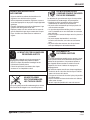


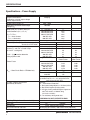
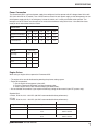


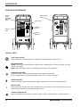
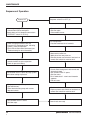

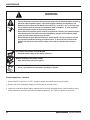
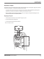

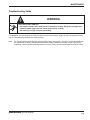

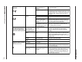
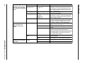

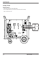
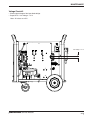

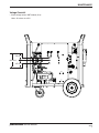

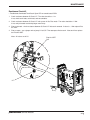


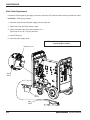
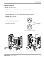
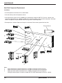
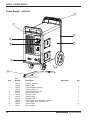


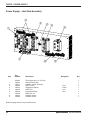
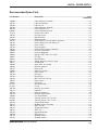

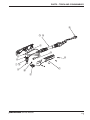

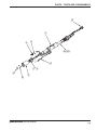
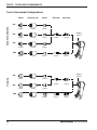
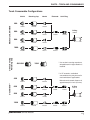


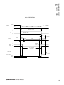


![PDF [1] - Dep SAE Soudage, Automatismes et Electronique location](http://vs1.manualzilla.com/store/data/005888267_1-8c649f384f0a877ffbc023ff9f75566c-150x150.png)