1
powermax600
Plasma Arc
Cutting System
Service Manual
803400 Revision 2
®
.
powermax600
Plasma Arc Cutting System
Service Manual
IM-340
(P/N 803400)
Revision 2 - NOVEMBER 1999
Hypertherm, Inc.
Hanover, NH USA
http://www.hypertherm.com
email:[email protected]
© Copyright 1999 Hypertherm, Inc.
All Rights Reserved
Hypertherm and Powermax are trademarks of Hypertherm, Inc.
and may be registered in the United States and/or other countries.
Hypertherm Offices Worldwide:
Hypertherm, Inc.
Etna Road, P.O. Box 5010
Hanover, NH 03755 USA
Tel.: (603) 643-3441 (Main Office)
Fax: (603) 643-5352 (All Departments)
Tel.: (800) 643-9878 (Technical Service)
Tel.: (800) 737-2978 (Customer Service)
email: [email protected] (General Information)
email: [email protected] (Technical/Customer Services)
Hypertherm Plasmatechnik GmbH
Technologiepark Hanau
Rodenbacher Chaussee 6
D–63457 Hanau-Wolfgang, Germany
Tel.: 49 6181 58 2100
Fax: 49 6181 58 2134
European Technical Support Organization (ETSO)
Technologiepark Hanau
Rodenbacher Chaussee 6
D–63457 Hanau-Wolfgang, Germany
Tel.: 49 6181 58 2100
Fax: 49 6181 58 2134
Hypertherm Singapore Pte Ltd
No. 19 Kaki Bukit Road 2
K.B. Warehouse Complex
Singapore 417847, Republic of Singapore
Tel.: 65 841 2489
Fax: 65 841 2490
Hypertherm U.K.
9 Berkeley Court • Manor Park
Runcorn, Cheshire, England WA7 1TQ
Tel.: 44 1928 579 074
Fax: 44 1928 579 604
France
10, Allée de I’lsara
F-95000 Cergy-Pontoise, France
Tel.: 33 1 34 24 03 05
Fax: 33 1 34 25 09 64
Italy
Via Torino 2
20123 Milan, Italy
Tel.: 39 02 725 46 312
Fax: 39 02 725 46 400
The Netherlands
Burg, Haverkampstraat 13
7091 CN Dinxperlo, Holland
Tel.: 31 315 655866
Fax: 31 315 655886
ELECTROMAGNETIC COMPATIBILITY
EMC INTRODUCTION
The CE power supplies have been built in
compliance with standard EN50199. To
ensure that the equipment works in a
compatible manner with other radio and
electronic systems, the equipment should
be installed and used in accordance with
the information below to achieve
electromagnetic compatibility.
The limits required by EN50199 may not
be adequate to completely eliminate
interference when the affected equipment
is in close proximity or has a high degree
of sensitivity. In such cases it may be
necessary to use other measures to
further reduce interference.
This plasma equipment should be used
only in an industrial environment. It may
be difficult to ensure electromagnetic
compatibility in a domestic environment.
e. Health of the people around, for
example the use of pacemakers and
hearing aids.
f. Equipment used for calibration or
measurement.
g. Immunity of other equipment in the
environment. User shall ensure that
other equipment being used in the
environment is compatible. This may
require additional protection measures.
h. Time of day that cutting or other
activities are to be carried out.
The size of the surrounding area to be
considered will depend on the structure of
the building and other activities that are
taking place. The surrounding area may
extend beyond the boundaries of the
premises.
METHODS OF REDUCING
EMISSIONS
Mains Supply
INSTALLATION AND USE
The user is responsible for installing and
using the plasma equipment according to
the manufacturer's instructions. If
electromagnetic disturbances are
detected then it shall be the responsibility
of the user to resolve the situation with the
technical assistance of the manufacturer.
In some cases this remedial action may be
as simple as earthing the cutting circuit,
see Earthing of Workpiece. In other cases
it could involve constructing an
electromagnetic screen enclosing the
power source and the work complete with
associated input filters. In all cases
electromagnetic disturbances must be
reduced to the point where they are no
longer troublesome.
ASSESSMENT OF AREA
Before installing the equipment the user
shall make an assessment of potential
electromagnetic problems in the
surrounding area. The following shall be
taken into account:
a. Other supply cables, control cables,
signalling and telephone cables; above,
below and adjacent to the cutting
equipment.
b. Radio and television transmitters and
receivers.
c. Computer and other control equipment.
d. Safety critical equipment, for example
guarding of industrial equipment.
Cutting equipment should be connected
to the mains supply according to the
manufacturer's recommendations. If
interference occurs, it may be necessary
to take additional precautions such as
filtering of the mains supply.
Consideration should be given to
shielding the supply cable of permanently
installed cutting equipment, in metallic
conduit or equivalent. Shielding should
be electrically continuous throughout its
length. The shielding should be
connected to the cutting mains supply so
that good electrical contact is maintained
between the conduit and the cutting
power source enclosure.
Maintenance of Cutting Equipment
The cutting equipment should be
routinely maintained according to the
manufacturer's recommendations. All
access and service doors and covers
should be closed and properly fastened
when the cutting equipment is in
operation. The cutting equipment should
not be modified in any way except for
those changes and adjustments covered
in the manufacturer's instructions. In
particular, the spark gaps of arc striking
and stabilizing devices should be
adjusted and maintained according to the
manufacturer's recommendations.
powermax600 Service Manual
Cutting Cables
The cutting cables should be kept as
short as possible and should be
positioned close together, running at or
close to the floor level.
Equipotential Bonding
Bonding of all metallic components in the
cutting installation and adjacent to it
should be considered. However, metallic
components bonded to the workpiece will
increase the risk that the operator could
receive a shock by touching these
metallic components and the electrode at
the same time. The operator should be
insulated from all such bonded metallic
components.
Earthing of Workpiece
Where the workpiece is not bonded to
earth for electrical safety, nor connected
to earth because of its size and position,
for example, ship's hull or building
steelwork, a connection bonding the
workpiece to earth may reduce
emissions in some, but not all instances.
Care should be taken to prevent the
earthing of the workpiece increasing the
risk of injury to users, or damage to other
electrical equipment. Where necessary,
the connection of the workpiece to earth
should be made by a direct connection to
the workpiece, but in some countries
where direct connection is not permitted,
the bonding should be achieved by
suitable capacitances selected
according to national regulations.
Note: The cutting circuit may or may not
be earthed for safety reasons. Changing
the earthing arrangements should only
be authorized by a person who is
competent to assess whether the
changes will increase the risk of injury, for
example, by allowing parallel cutting
current return paths which may damage
the earth circuits of other equipment.
Further guidance is given in IEC TC26
(sec)94 and IEC TC26/108A/CD Arc
Welding Equipment Installation and Use.
Screening and Shielding
Selective screening and shielding of
other cables and equipment in the
surrounding area may alleviate problems
of interference. Screening of the entire
plasma cutting installation may be
considered for special applications.
i
WARRANTY
WARNING
Genuine Hypertherm parts are the factoryrecommended replacement parts for your
Hypertherm system. Any damage caused by the use
of other than genuine Hypertherm parts may not be
covered by the Hypertherm warranty.
GENERAL
Hypertherm, Inc. warrants that products shall be free from
defects in materials and workmanship, under proper and
normal use for which such equipment is recommended, for
a period of two (2) years, except only with respect to the
torch, for which the warranty period shall be one (1) year,
from the date of its delivery to you.
Hypertherm, at its sole option, shall repair, replace, or
adjust, free of charge, any Products covered by this warranty which shall be returned with Hypertherm's prior authorization (which shall not be unreasonably withheld), properly packed, to Hypertherm's place of business in Hanover,
New Hampshire, all costs, insurance and freight prepaid,
and which examination proves not to be free from defects in
materials and workmanship. Hypertherm shall not be liable
for any repairs, replacements, or adjustments of Products
covered by this warranty, except those made pursuant to
this paragraph or with Hypertherm's written consent. This
warranty shall not apply to any Product which has been
mishandled, incorrectly installed, modified or assembled by
you or any other person. Hypertherm shall be liable for
breach of this warranty only if it receives written notice of
such breach within the applicable warranty period specified
herein above. THE FOREGOING SHALL CONSTITUTE
THE SOLE REMEDY TO DISTRIBUTORS OR THEIR
CUSTOMERS FOR ANY BREACH BY HYPERTHERM OF
ITS WARRANTY.
PATENT INDEMNITY
Except only in cases of Products not manufactured by
Hypertherm or manufactured by a person other than Hypertherm not in strict conformity with Hypertherm's specifications, and in cases of designs, processes, formulae or
combinations not developed or purported to be developed
by Hypertherm, Hypertherm agrees to indemnify, protect
and hold harmless Distributors and their customers against
any and all liability or claims in any manner imposed upon
or accruing against Distributors and their customers because of the use in or about the construction or operation of
equipment or any design, system, formula, combination,
article or material which infringes or alleges to infringe on
ii
any patent or other right. Distributors shall notify Hypertherm promptly upon learning of any action or threatened
action in connection with any such alleged infringement,
and each party may appoint its own counsel for any such
action or threatened action.
DISCLAIMER OF OTHER WARRANTIES
HYPERTHERM MAKES NO WARRANTIES REGARDING
PRODUCTS MANUFACTURED BY IT OR OTHERS (INCLUDING WITHOUT IMPLIED LIMITATION WARRANTIES AS TO MERCHANTABILITY OR FITNESS FOR A
PARTICULAR PURPOSE), EITHER EXPRESS OR IMPLIED, EXCEPT AS PROVIDED HEREIN. This warranty is
in lieu of any and all warranties, express or implied, by law
or otherwise; and Distributors are not authorized to give any
other warranty purporting to be binding upon Hypertherm
upon resale of Products to their customers. IN NO EVENT
shall Hypertherm be liable for incidental or consequential
damages or injury to the person or property of anyone by
reason of any defect in any Equipment sold hereunder.
UPON RECEIPT
1. Verify that all parts and items on your order have been
received. Alert your distributor if any parts or items are
damaged or missing.
2. Inspect the power supply for any physical damage that
may have occurred during shipping. If there is evidence
of damage, refer to the Claims section below. All
communications regarding this equipment must include the model number and serial number located on
the back of the Powermax600.
3. Before setting up and operating the Powermax600,
read the Safety section of this manual.
CLAIMS
Claims for damage during shipment — If your unit was
damaged during shipment, you must file a claim with the
carrier. Hypertherm will furnish you with a copy of the bill of
lading upon request. If you need additional assistance, call
Customer Service listed in the front of this manual, or your
authorized Hypertherm distributor.
Claims for defective or missing merchandise — If any of
the merchandise is defective or missing, call your
authorized Hypertherm distributor. If you need additional
assistance, call Customer Service listed in the front of this
manual.
powermax600 Service Manual
TABLE OF CONTENTS
Electromagnetic Compatibility .................................................................................................................................. i
Warranty
............................................................................................................................................................ ii
SECTION 1 - SAFETY
RECOGNIZE SAFETY INFORMATION ............................................................................................................... 1-2
FOLLOW SAFETY INSTRUCTIONS ................................................................................................................... 1-2
CUTTING CAN CAUSE FIRE OR EXPLOSION .................................................................................................. 1-2
ELECTRIC SHOCK CAN KILL ............................................................................................................................. 1-3
CUTTING CAN PRODUCE TOXIC FUMES ........................................................................................................ 1-3
PLASMA ARC CAN CAUSE INJURY AND BURNS ............................................................................................ 1-4
ARC RAYS CAN BURN EYES AND SKIN ........................................................................................................... 1-4
GROUNDING SAFETY ........................................................................................................................................ 1-4
COMPRESSED GAS EQUIPMENT SAFETY ...................................................................................................... 1-5
GAS CYLINDERS CAN EXPLODE IF DAMAGED .............................................................................................. 1-5
NOISE CAN DAMAGE HEARING ....................................................................................................................... 1-5
PACEMAKER AND HEARING AID OPERATION ................................................................................................ 1-5
ADDITIONAL SAFETY INFORMATION ............................................................................................................... 1-5
WARNING LABEL ................................................................................................................................................ 1-6
SECTION 1a - SÉCURITÉ
IDENTIFIER LES CONSIGNES DE SÉCURITÉ ................................................................................................ 1a-2
SUIVRE LES INSTRUCTIONS DE SÉCURITÉ ................................................................................................. 1a-2
LE COUPAGE PEUT PROVOQUER UN INCENDIE OU UNE EXPLOSION .................................................... 1a-2
LES CHOCS ÉLECTRIQUES PEUVENT ÊTRE FATALS .................................................................................. 1a-3
LE COUPAGE PEUT PRODUIRE DES VAPEURS TOXIQUES ........................................................................ 1a-3
L’ARC PLASMA PEUT PROVOQUER DES BLESSURES OU DES BRÛLURES ............................................ 1a-4
LES RAYONS DE L’ARC PEUVENT BRÛLER LES YEUX ET LA PEAU .......................................................... 1a-4
MISE À LA MASSE ET À LA TERRE ................................................................................................................. 1a-4
SÉCURITÉ DES BOUTEILLES DE GAZ COMPRIMÉ ...................................................................................... 1a-5
LES BOUTEILLES DE GAZ COMPRIMÉ PEUVENT EXPLOSER EN CAS DE DOMMAGES ......................... 1a-5
LE BRUIT PEUT PROVOQUER DES PROBLÈMES AUDITIFS ....................................................................... 1a-5
PACEMAKERS ET PROTHÈSES AUDITIVES .................................................................................................. 1a-5
ÉTIQUETTE DE SÉCURITÉ .............................................................................................................................. 1a-6
SECTION 2 SPECIFICATIONS
SPECIFICATIONS, POWER SUPPLY ..................................................................................................................
SPECIFICATIONS, PAC123 TORCHES ...............................................................................................................
SETUP SPECIFICATIONS ...................................................................................................................................
INSTALL POWER CORD PLUG ...........................................................................................................................
CHECK REQUIRED INPUT VOLTAGE ................................................................................................................
S MARK (230/400 VOLT ONLY) .......................................................................................................................
GROUNDING REQUIREMENTS ..........................................................................................................................
POWER CORD / EXTENSION CORD ..................................................................................................................
GAS REQUIREMENTS .........................................................................................................................................
LINE VOLTAGE DISCONNECT BOX ...................................................................................................................
powermax600 Service Manual
2-2
2-3
2-4
2-4
2-4
2-4
2-5
2-5
2-6
2-6
iii
TABLE OF CONTENTS
SECTION 3 MAINTENANCE
CONTROLS AND INDICATORS ........................................................................................................................... 3-2
INDICATOR LAMPS ............................................................................................................................................. 3-2
CONTROLS. ......................................................................................................................................................... 3-2
THEORY OF OPERATION ................................................................................................................................... 3-3
GENERAL ............................................................................................................................................................. 3-3
230/400 VOLT FUNCTIONAL DESCRIPTION ...................................................................................................... 3-4
208-240/480 VOLT FUNCTIONAL DESCRIPTION .............................................................................................. 3-6
SEQUENCE OF OPERATION .............................................................................................................................. 3-8
TROUBLESHOOTING .......................................................................................................................................... 3-9
TEST EQUIPMENT ............................................................................................................................................... 3-9
TROUBLESHOOTING PROCEDURES AND SEQUENCE .................................................................................. 3-9
VISUAL INSPECTION - EXTERNAL .................................................................................................................... 3-9
VISUAL INSPECTION - INTERNAL ................................................................................................................... 3-10
RESISTANCE CHECKS ...................................................................................................................................... 3-11
TROUBLESHOOTING GUIDE ............................................................................................................................ 3-14
VOLTAGE CHECKS ............................................................................................................................................ 3-21
COMPONENT REPLACEMENT ......................................................................................................................... 3-26
POWER CORD REPLACEMENT ....................................................................................................................... 3-26
TORCH LEAD REPLACEMENT (MODELS WITHOUT QUICK DISCONNECT) ............................................... 3-27
AIR FILTER ELEMENT REPLACEMENT ........................................................................................................... 3-28
WORK CABLE REPLACEMENT ........................................................................................................................ 3-30
CAPACITOR REPLACEMENT ........................................................................................................................... 3-31
HEAT SINK COMPONENT REPLACEMENT ..................................................................................................... 3-32
SECTION 4 PARTS LIST - 400/230V CE
POWER SUPPLY – EXTERIOR ...........................................................................................................................
POWER SUPPLY – FRONT INTERIOR RIGHT SIDE ..........................................................................................
POWER SUPPLY – BACK INTERIOR RIGHT SIDE ............................................................................................
POWER SUPPLY – INTERIOR FAN SIDE ...........................................................................................................
POWER SUPPLY – HEAT SINK ASSEMBLY .......................................................................................................
RECOMMENDED SPARE PARTS - POWERMAX600- 230/400V .......................................................................
4-2
4-3
4-4
4-5
4-6
4-7
SECTION 5 PARTS LIST - 208-240/480V
POWER SUPPLY – EXTERIOR ...........................................................................................................................
POWER SUPPLY – FRONT INTERIOR RIGHT SIDE ..........................................................................................
POWER SUPPLY – BACK INTERIOR RIGHT SIDE ............................................................................................
POWER SUPPLY – INTERIOR FAN SIDE ...........................................................................................................
POWER SUPPLY – HEAT SINK ASSEMBLY .......................................................................................................
RECOMMENDED SPARE PARTS - POWERMAX600- 208-240/480V ................................................................
5-2
5-3
5-4
5-5
5-6
5-7
SECTION 6 PARTS LIST - TORCH AND CONSUMABLES
PAC123T HAND TORCH ASSEMBLY (NO QUICK DISCONNECT) .................................................................... 6-2
PAC123T HAND TORCH ASSEMBLY (WITH QUICK DISCONNECT) ................................................................ 6-4
PAC123M MACHINE TORCH ASSEMBLY (NO QUICK DISCONNECT) ............................................................. 6-6
PAC123M MACHINE TORCH ASSEMBLY (WITH QUICK DISCONNECT) ......................................................... 6-8
TORCH CONSUMABLES ................................................................................................................................... 6-10
RECOMMENDED SPARE PARTS - PAC123 TORCH ........................................................................................ 6-11
SECTION 7 WIRING DIAGRAMS
iv
powermax600 Service Manual
SAFETY
Section 1
SAFETY
In this section:
Recognize Safety Information ................................................................................ 1-2
Follow Safety Instructions ...................................................................................... 1-2
Cutting Can Cause Fire or Explosion ..................................................................... 1-2
Electric Shock Can Kill ...........................................................................................1-3
Cutting Can Produce Toxic Fumes ......................................................................... 1-3
Plasma Arc Can Cause Injury and Burns ............................................................... 1-4
Arc Rays Can Burn Eyes and Skin ........................................................................ 1-4
Grounding Safety ...................................................................................................1-4
Compressed Gas Equipment Safety ...................................................................... 1-5
Gas Cylinders Can Explode if Damaged ................................................................ 1-5
Noise Can Damage Hearing .................................................................................. 1-5
Pacemaker and Hearing Aid Operation .................................................................. 1-5
Additional Safety Information ................................................................................. 1-5
Warning Label ........................................................................................................ 1-6
Hypertherm Plasma Systems
1-1
SAFETY
RECOGNIZE SAFETY INFORMATION
The symbols shown in this section are used to identify
potential hazards. When you see a safety symbol in
this manual or on your machine, understand the
potential for personal injury, and follow the related
instructions to avoid the hazard.
FOLLOW SAFETY INSTRUCTIONS
Read carefully all safety messages in this manual and
safety labels on your machine.
• Keep the safety labels on your machine in good
condition. Replace missing or damaged labels
immediately.
• Learn how to operate the machine and how to use
the controls properly. Do not let anyone operate it
without instruction.
• Keep your machine in proper working condition.
Unauthorized modifications to the machine may
affect safety and machine service life.
DANGER
WARNING
CAUTION
A signal word DANGER or WARNING is used with a
safety symbol. DANGER identifies the most serious
hazards.
• DANGER and WARNING safety labels are located
on your machine near specific hazards.
• WARNING safety messages precede related instructions in this manual that may result in injury or death
if not followed correctly.
• CAUTION safety messages precede related instructions in this manual that may result in damage to
equipment if not followed correctly.
CUTTING CAN CAUSE FIRE OR EXPLOSION
Fire Prevention
• Be sure the area is safe before doing any cutting.
Keep a fire extinguisher nearby.
• Remove all flammables within 35 feet (10 m) of the
cutting area.
• Quench hot metal or allow it to cool before handling
or before letting it touch combustible materials.
• Never cut containers with potentially flammable
materials inside – they must be emptied and
properly cleaned first.
• Ventilate potentially flammable atmospheres before
cutting.
• When cutting with oxygen as the plasma gas, an
exhaust ventilation system is required.
WARNING
Explosion Hazard
Argon-Hydrogen and Methane
Hydrogen and methane are flammable gases that
present an explosion hazard. Keep flames away from
cylinders and hoses that contain methane or hydrogen
mixtures. Keep flames and sparks away from the torch
when using methane or argon-hydrogen plasma.
WARNING
Hydrogen Detonation with Aluminum Cutting
•
Explosion Prevention
• Do not use the plasma system if explosive dust or
vapors may be present.
• Do not cut pressurized cylinders, pipes, or any
closed container.
• Do not cut containers that have held combustible
materials.
1-2
11-98
•
When cutting aluminum underwater, or with the
water touching the underside of the aluminum, free
hydrogen gas may collect under the workpiece and
detonate during plasma cutting operations.
Install an aeration manifold on the floor of the water
table to eliminate the possibility of hydrogen detonation. Refer to the Appendix section of this manual
for aeration manifold details.
Hypertherm Plasma Systems
SAFETY
ELECTRIC SHOCK CAN KILL
Touching live electrical parts can cause a fatal shock or
severe burn.
• Operating the plasma system completes an electrical
circuit between the torch and the workpiece. The
workpiece and anything touching the workpiece are
part of the electrical circuit.
• Never touch the torch body, workpiece or the water in
a water table when the plasma system is operating.
Electric Shock Prevention
All Hypertherm plasma systems use high voltage in
the cutting process (200 to 400 VDC are common).
Take the following precautions when operating this
system:
• Wear insulated gloves and boots, and keep your
body and clothing dry.
• Do not stand, sit or lie on – or touch – any wet
surface when using the plasma system.
• Insulate yourself from work and ground using dry
insulating mats or covers big enough to prevent any
physical contact with the work or ground. If you must
work in or near a damp area, use extreme caution.
• Provide a disconnect switch close to the power
supply with properly sized fuses. This switch allows
the operator to turn off the power supply quickly in an
emergency situation.
• When using a water table, be sure that it is correctly
connected to earth ground.
• Install and ground this equipment according to the
instruction manual and in accordance with national
and local codes.
• Inspect the input power cord frequently for damage
or cracking of the cover. Replace a damaged power
cord immediately. Bare wiring can kill.
• Inspect and replace any worn or damaged torch
leads.
• Do not pick up the workpiece, including the waste
cutoff, while you cut. Leave the workpiece in place or
on the workbench with the work cable attached
during the cutting process.
• Before checking, cleaning or changing torch parts,
disconnect the main power or unplug the power
supply.
• Never bypass or shortcut the safety interlocks.
• Before removing any power supply or system enclosure cover, disconnect electrical input power. Wait 5
minutes after disconnecting the main power to allow
capacitors to discharge.
• Never operate the plasma system unless the power
supply covers are in place. Exposed power supply
connections present a severe electrical hazard.
• When making input connections, attach proper
grounding conductor first.
• Each Hypertherm plasma system is designed to be
used only with specific Hypertherm torches. Do not
substitute other torches which could overheat and
present a safety hazard.
CUTTING CAN PRODUCE TOXIC FUMES
Cutting can produce toxic fumes and gases that
deplete oxygen and cause injury or death.
•
•
•
Keep the cutting area well ventilated or use an
approved air-supplied respirator.
Do not cut in locations near degreasing, cleaning or
spraying operations. The vapors from certain
chlorinated solvents decompose to form phosgene
gas when exposed to ultraviolet radiation.
Do not cut metal coated or containing toxic materials, such as zinc (galvanized), lead, cadmium or
Hypertherm Plasma Systems
•
•
beryllium, unless the area is well ventilated and the
operator wears an air-supplied respirator. The
coatings and any metals containing these elements
can produce toxic fumes when cut.
Never cut containers with potentially toxic materials
inside – they must be emptied and properly cleaned
first.
This product, when used for welding or cutting,
produces fumes or gases which contain chemicals
known to the State of California to cause birth
defects and, in some cases, cancer.
1-3
8-99
SAFETY
PLASMA ARC CAN CAUSE INJURY AND BURNS
Instant-On Torches
Plasma arc comes on immediately when the torch
switch is activated.
The plasma arc will cut quickly through gloves and
skin.
• Keep away from the torch tip.
• Do not hold metal near the cutting path.
• Never point the torch toward yourself or others.
ARC RAYS CAN BURN EYES AND SKIN
Eye Protection Plasma arc rays produce intense
visible and invisible (ultraviolet and infrared) rays that
can burn eyes and skin.
• Use eye protection in accordance with applicable
national or local codes.
• Wear eye protection (safety glasses or goggles with
side shields, or a welding helmet) with appropriate
lens shading to protect your eyes from the arc’s
ultraviolet and infrared rays.
Arc Current
Up to 100 A
100-200 A
200-400 A
Over 400 A
Lens Shade
AWS (USA)
ISO 4850
No. 8
No. 11
No. 10
No. 11-12
No. 12
No. 13
No. 14
No. 14
GROUNDING SAFETY
Work Cable Attach the work cable securely to the
workpiece or the work table with good metal-to-metal
contact. Do not connect it to the piece that will fall away
when the cut is complete.
Work Table Connect the work table to an earth
ground, in accordance with appropriate national or local
electrical codes.
1-4
4-99
Skin Protection Wear protective clothing to protect
against burns caused by ultraviolet light, sparks and
hot metal.
• Gauntlet gloves, safety shoes and hat.
• Flame-retardant clothing to cover all exposed areas.
• Cuffless trousers to prevent entry of sparks and
slag.
• Remove any combustibles, such as a butane lighter
or matches, from your pockets before cutting.
Cutting Area Prepare the cutting area to reduce
reflection and transmission of ultraviolet light:
• Paint walls and other surfaces with dark colors to
reduce reflection.
• Use protective screens or barriers to protect others
from flash and glare.
• Warn others not to watch the arc. Use placards or
signs.
Input Power
• Be sure to connect the power cord ground wire to
the ground in the disconnect box.
• If installation of the plasma system involves connecting the power cord to the power supply, be sure to
connect the power cord ground wire properly.
• Place the power cord's ground wire on the stud first,
then place any other ground wires on top of the
power cord ground. Fasten the retaining nut tightly.
• Tighten all electrical connections to avoid excessive
heating.
Hypertherm Plasma Systems
SAFETY
COMPRESSED GAS EQUIPMENT SAFETY
• Never lubricate cylinder valves or regulators with oil
or grease.
• Use only correct gas cylinders, regulators, hoses and
fittings designed for the specific application.
• Maintain all compressed gas equipment and associated parts in good condition.
• Label and color-code all gas hoses to identify the
type of gas in each hose. Consult applicable national
or local codes.
GAS CYLINDERS CAN EXPLODE
IF DAMAGED
Gas cylinders contain gas under high pressure. If
damaged, a cylinder can explode.
• Handle and use compressed gas cylinders in accordance with applicable national or local codes.
• Never use a cylinder that is not upright and secured
in place.
• Keep the protective cap in place over valve except
when the cylinder is in use or connected for use.
• Never allow electrical contact between the plasma
arc and a cylinder.
• Never expose cylinders to excessive heat, sparks,
slag or open flame.
• Never use a hammer, wrench or other tool to open a
stuck cylinder valve.
PACEMAKER AND HEARING
AID OPERATION
NOISE CAN DAMAGE HEARING
Prolonged exposure to noise from cutting or gouging
can damage hearing.
• Use approved ear protection when using plasma
system.
• Warn others nearby about the noise hazard.
Pacemaker and hearing aid operation can be affected
by magnetic fields from high currents.
Pacemaker and hearing aid wearers should consult a
doctor before going near any plasma arc cutting and
gouging operations.
To reduce magnetic field hazards:
• Keep both the work cable and the torch lead to one
side, away from your body.
• Route the torch leads as close as possible to the
work cable.
• Do not wrap or drape the torch lead or work cable
around your body.
• Keep as far away from the power supply as possible.
ADDITIONAL SAFETY INFORMATION
1.
2.
3.
4.
ANSI Standard Z49.1, Safety in Welding and Cutting,
American Welding Society, 550 LeJeune Road
P.O. Box 351020, Miami, FL 33135
ANSI Standard Z49.2, Fire Prevention in the Use of Cutting and
Welding Processes, American National Standards Institute
1430 Broadway, New York, NY 10018
ANSI Standard Z87.1, Safe Practices for Occupation and
Educational Eye and Face Protection, American National
Standards Institute, 1430 Broadway, New York, NY 10018
AWS F4.1, Recommended Safe Practices for the Preparation for
Welding and Cutting of Containers and Piping That Have Held
Hazardous Substances, American Welding Society
550 LeJeune Road, P.O. Box 351040, Miami, FL 33135
Hypertherm Plasma Systems
AWS F5.2, Recommended Safe Practices for Plasma Arc
Cutting, American Welding Society
550 LeJeune Road, P.O. Box 351040, Miami, FL 33135
6. CGA Pamphlet P-1, Safe Handling of Compressed Gases in
Cylinders, Compressed Gas Association
1235 Jefferson Davis Highway, Arlington, VA 22202
7. CSA Standard W117.2, Code for Safety in Welding and Cutting,
Canadian Standards Association Standard Sales
178 Rexdale Boulevard, Rexdale, Ontario M9W 1R3, Canada
8. NFPA Standard 51B, Cutting and Welding Processes, National
Fire Protection Association
470 Atlantic Avenue, Boston, MA 02210
9. NFPA Standard 70–1978, National Electrical Code, National Fire
Protection Association, 470 Atlantic Avenue, Boston, MA 02210
10. OSHA, Safety and Health Standards, 29FR 1910
U.S. Government Printing Office, Washington, D.C. 20402
5.
1-5
11-98
SAFETY
WARNING LABEL
This warning label is affixed to some power supplies. It is
important that the operator and maintenance technician
understand the intent of these warning symbols as described.
The numbered text corresponds to the numbered boxes on
the label.
1.
Cutting sparks can cause explosion or fire.
1.1 Keep flammables away from cutting.
1.2 Keep a fire extinguisher nearby, and have a
watchperson ready to use it.
1.3 Do not cut on any closed containers.
2.
The plasma arc can cause injury and burns.
2.1 Turn off power before disassembling torch.
2.2 Do not hold the material near cutting path.
2.3 Wear complete body protection.
3.
Electric shock from torch or wiring can kill.
Protect yourself from electric shock.
3.1 Wear insulating gloves. Do not wear wet or
damaged gloves.
3.2 Insulate yourself from work and ground.
3.3 Disconnect input plug or power before
working on machine.
4.
Breathing cutting fumes can be hazardous
to your health.
4.1 Keep your head out of the fumes.
4.2 Use forced ventilation or local exhaust to
remove the fumes.
4.3 Use ventilating fan to remove the fumes.
5.
Arc rays can burn eyes and injure skin.
5.1 Wear hat and safety glasses. Use ear
protection and button shirt collar. Use
welding helmet with correct shade of filter.
Wear complete body protection.
1-6
8-99
6.
Become trained and read the instructions
before working on the machine or cutting.
7.
Do not remove or paint over (cover)
warning labels.
Hypertherm Plasma Systems
SÉCURITÉ
Section 1a
SÉCURITÉ
Cette section comprend:
IDENTIFIER LES CONSIGNES DE SÉCURITÉ ..............................................1a-2
SUIVRE LES INSTRUCTIONS DE SÉCURITÉ ...............................................1a-2
LE COUPAGE PEUT PROVOQUER UN INCENDIE OU UNE EXPLOSION .. 1a-2
LES CHOCS ÉLECTRIQUES PEUVENT ÊTRE FATALS ................................ 1a-3
LE COUPAGE PEUT PRODUIRE DES VAPEURS TOXIQUES ...................... 1a-3
L’ARC PLASMA PEUT PROVOQUER DES BLESSURES
OU DES BRÛLURES .......................................................................................1a-4
LES RAYONS DE L’ARC PEUVENT BRÛLER LES YEUX ET LA PEAU ........ 1a-4
MISE À LA MASSE ET À LA TERRE ...............................................................1a-4
SÉCURITÉ DES BOUTEILLES DE GAZ COMPRIMÉ ....................................1a-5
LES BOUTEILLES DE GAZ COMPRIMÉ PEUVENT EXPLOSER EN CAS DE
DOMMAGES ...............................................................................................1a-5
LE BRUIT PEUT PROVOQUER DES PROBLÈMES AUDITIFS ..................... 1a-5
PACEMAKERS ET PROTHÈSES AUDITIVES ................................................1a-5
ÉTIQUETTE DE SÉCURITÉ ............................................................................1a-6
HYPERTHERM Systèmes plasma
1a-1
08/99
SÉCURITÉ
IDENTIFIER LES CONSIGNES
DE SÉCURITÉ
Les symboles indiqués dans cette section sont utilisés pour
identifier les risques éventuels. Si vous trouvez un symbole
de sécurité, que ce soit dans ce manuel ou sur
l’équipement, soyez conscient des risques de blessures et
suivez les instructions correspondantes afin d’éviter ces
risques.
SUIVRE LES INSTRUCTIONS
DE SÉCURITÉ
Lire attentivement toutes les consignes de sécurité dans le
présent manuel et sur les étiquettes de sécurité se trouvant
sur la machine.
• Les étiquettes de sécurité doivent rester lisibles.
Remplacer immédiatement les étiquettes manquantes ou
abîmées.
• Apprendre à faire fonctionner la machine et à utiliser
correctement les commandes. Ne laisser personne utiliser
la machine sans connaître son fonctionnement.
• Garder la machine en bon état. Des modifications non
autorisées sur la machine peuvent engendrer des
problèmes de sécurité et raccourcir la durée d’utilisation
de l’équipement.
DANGER AVERTISSEMENT PRÉCAUTION
Les signaux DANGER ou AVERTISSEMENT sont utilisés
avec un symbole de sécurité, DANGER correspondant aux
risques les plus sérieux.
• Les étiquettes de sécurité DANGER et AVERTISSEMENT sont situées sur la machine pour signaler certains
dangers spécifiques.
• Les messages d’AVERTISSEMENT précèdent les
instructions d’utilisation expliquées dans ce manuel et
signalent les risques de blessures ou de mort au cas où
ces instructions ne seraient pas suivies correctement.
• Les messages de PRÉCAUTION précèdent les
instructions d’utilisation contenues dans ce manuel et
signalent que le matériel risque d’être endommagé si les
instructions ne sont pas suivies correctement.
LE COUPAGE PEUT PROVOQUER UN INCENDIE
OU UNE EXPLOSION
Prévention des incendies
• Avant de commencer, s’assurer que la zone de coupage
ne présente aucun danger. Conserver un extincteur à
proximité.
• Éloigner toute matière inflammable à une distance d’au
moins 10 m du poste de coupage.
• Tremper le métal chaud ou le laisser refroidir avant de
le manipuler ou avant de le mettre en contact avec des
matériaux combustibles.
• Ne jamais couper des récipients pouvant contenir des
matières inflammables avant de les avoir vidés et
nettoyés correctement.
• Aérer toute atmosphère potentiellement inflammable
avant d’utiliser un système plasma.
• Lors de l’utilisation d’oxygène comme gaz plasma, un
système de ventilation par aspiration est nécessaire.
Prévention des explosions
• Ne pas couper en présence de poussière ou de vapeurs.
• Ne pas couper de bouteilles, de tuyaux ou autres
récipients fermés et pressurisés.
• Ne pas couper de récipients contenant des matières
combustibles.
1a-2
08/99
AVERTISSEMENT
Risque d’explosion
Argon-hydrogène et méthane
L’hydrogène et le méthane sont des gaz inflammables et
potentiellement explosifs. Conserver à l’écart de toute
flamme les bouteilles et tuyaux contenant des mélanges à
base d’hydrogène ou de méthane. Maintenir toute flamme
et étincelle à l’écart de la torche lors de l’utilisation d’un
plasma d’argon-hydrogène ou de méthane.
AVERTISSEMENT
Détonation de l’hydrogène lors du
coupage de l’aluminium
• Lors du coupage de l’aluminium sous l’eau, ou si l’eau
touche la partie inférieure de la pièce d’aluminium, de
l’hydrogène libre peut s’accumuler sous la pièce à couper
et détonner lors du coupage plasma.
• Installer un collecteur d’aération au fond de la table à eau
afin d’éliminer les risques de détonation de l’hydrogène.
Se référer à l’annexe du manuel pour plus de
renseignements sur les collecteurs d’aération.
HYPERTHERM Systèmes plasma
SÉCURITÉ
LES CHOCS ÉLECTRIQUES PEUVENT ÊTRE FATALS
Toucher une pièce électrique sous tension peut provoquer
un choc électrique fatal ou des brûlures graves.
• La mise en fonctionnement du système plasma ferme un
circuit électrique entre la torche et la pièce à couper. La
pièce à couper et tout autre élément en contact avec cette
pièce font partie du circuit électrique.
• Ne jamais toucher le corps de la torche, la pièce à couper
ou l’eau de la table à eau pendant le fonctionnement du
système plasma.
Prévention des chocs électriques
Tous les systèmes plasma Hypertherm utilisent des hautes
tensions pour le coupage (souvent de 200 à 400 V).On doit
prendre les précautions suivantes quand on utilise le
système plasma :
• Porter des bottes et des gants isolants et garder le corps
et les vêtements au sec.
• Ne pas se tenir, s’asseoir ou se coucher sur une surface
mouillée, ni la toucher quand on utilise le système
plasma.
• S’isoler de la surface de travail et du sol en utilisant des
tapis isolants secs ou des couvertures assez grandes
pour éviter tout contact physique avec le travail ou le sol.
S’il s’avère nécessaire de travailler dans ou près d’un
endroit humide, procéder avec une extrême prudence.
• Installer un sectionneur avec fusibles appropriés, à
proximité de la source de courant. Ce dispositif permet à
l’opérateur d’arrêter rapidement la source de courant en
cas d’urgence.
• En cas d’utilisation d’une table à eau, s’assurer que cette
dernière est correctement mise à la terre.
• Installer et mettre à la terre l’équipement selon les
instructions du présent manuel et conformément aux
codes électriques locaux et nationaux.
• Inspecter fréquemment le cordon d’alimentation primaire
pour s’assurer qu’il n’est ni endommagé, ni fendu.
Remplacer immédiatement un cordon endommagé. Un
câble dénudé peut tuer.
• Inspecter et remplacer les câbles de la torche qui sont
usés ou endommagés.
• Ne pas saisir la pièce à couper ni les chutes lors du
coupage. Laisser la pièce à couper en place ou sur la
table de travail, le câble de retour connecté lors du
coupage.
• Avant de vérifier, de nettoyer ou de remplacer les pièces
de la torche, couper l’alimentation ou débrancher la prise
de courant.
• Ne jamais contourner ou court-circuiter les verrouillages
de sécurité.
• Avant d’enlever le capot du système ou de la source de
courant, couper l’alimentation électrique. Attendre ensuite
5 minutes pour que les condensateurs se déchargent.
• Ne jamais faire fonctionner le système plasma sans que
les capots de la source de courant ne soient en place.
Les raccords exposés de la source de courant sont
extrêmement dangereux.
• Lors de l’installation des connexions, attacher tout d’abord
la prise de terre appropriée.
• Chaque système plasma Hypertherm est conçu pour être
utilisé uniquement avec des torches Hypertherm
spécifiques. Ne pas utiliser des torches inappropriées qui
pourraient surchauffer et présenter des risques pour la
sécurité.
LE COUPAGE PEUT PRODUIRE DES VAPEURS TOXIQUES
Le coupage peut produire des vapeurs et des gaz toxiques
qui réduisent le niveau d’oxygène dans l’air et peuvent
provoquer des blessures, voire la mort.
• Conserver le poste de coupage bien aéré ou utiliser un
masque respiratoire homologué.
• Ne pas procéder au coupage près d’endroits où
s’effectuent le dégraissage, le nettoyage ou la
vaporisation. Certains solvants chlorés se décomposent
sous l’effet des rayons ultraviolets et forment du
phosgène.
HYPERTHERM Systèmes plasma
• Ne pas couper des métaux peints ou contenant des
matières toxiques comme le zinc (galvanisé), le plomb, le
cadmium ou le béryllum, à moins que la zone de travail
soit très bien ventilée et que l’opérateur porte un masque
respiratoire. Les revêtements et métaux contenant ces
matières peuvent produire des vapeurs toxiques lors du
coupage.
• Ne jamais couper de récipients pouvant contenir des
matières inflammables avant de les avoir vidés et
nettoyés correctement.
1a-3
08/99
SÉCURITÉ
L’ARC PLASMA PEUT PROVOQUER DES BLESSURES OU DES BRÛLURES
Torches à allumage instantané
L’arc plasma s’allume immédiatement après que la torche
soit mise en marche.
L’arc plasma coupe facilement les gants et la peau.
• Rester éloigné de l’extrémité de la torche.
• Ne pas tenir de métal près de la trajectoire de coupe.
• Ne jamais pointer la torche vers soi ou d’autres
personnes.
LES RAYONS DE L’ARC PEUVENT BRÛLER LES YEUX ET LA PEAU
Protection des yeux Les rayons de l’arc plasma
produisent de puissants rayons visibles ou invisibles
(ultraviolets et infrarouges) qui peuvent brûler les yeux et la
peau.
• Utiliser des lunettes de sécurité conformément aux codes
locaux ou nationaux en vigueur.
• Porter des lunettes de protection (lunettes ou masque
muni d’écrans latéraux ou encore masque de soudure)
avec des verres teintés appropriés pour protéger les yeux
des rayons ultraviolets et infrarouges de l’arc.
Courant de l’arc
Jusqu’à 100 A
100-200 A
200-400 A
Plus de 400 A
Puissance des verres teintés
AWS (É.-U.)
ISO 4850
No 11
No 8
No 10
No 11-12
No 12
No 13
No 14
No 14
Protection de la peau Porter des vêtements de sécurité
pour se protéger contre les brûlures que peuvent causer les
rayons ultraviolets, les étincelles et le métal brûlant :
MISE À LA MASSE ET À LA TERRE
Câble de retour Bien fixer le câble de retour (ou de
masse) à la pièce à couper ou à la table de travail de façon
à assurer un bon contact métal-métal. Ne pas fixer le câble
de retour à la partie de la pièce qui doit se détacher.
Table de travail Raccorder la table de travail à la terre,
conformément aux codes de sécurité locaux ou nationaux
appropriés.
1a-4
08/99
• Gants à crispin, chaussures et casque de sécurité.
• Vêtements ignifuges couvrant toutes les parties exposées
du corps.
• Pantalon sans revers pour éviter que des étincelles ou
des scories puissent s’y loger.
• Avant le coupage, retirer de ses poches tout objet
combustible comme les briquets au butane ou les
allumettes.
Zone de coupage Préparer la zone de coupage afin de
réduire la réverbération et la transmission de la lumière
ultraviolette :
• Peindre les murs et autres surfaces de couleur sombre
pour réduire la réflexion de la lumière.
• Utiliser des écrans et autres dispositifs de protection afin
de protéger les autres personnes de la lumière et de la
réverbération.
• Prévenir les autres personnes de ne pas regarder l’arc.
Utiliser des affiches ou des panneaux.
Alimentation
• S’assurer que le fil de terre du cordon d’alimentation est
connecté à la terre dans le coffret du sectionneur.
• S’il est nécessaire de brancher le cordon d’alimentation à
la source de courant lors de l’installation du système,
s’assurer que le fil de terre est correctement branché.
• Placer tout d’abord le fil de terre du cordon d’alimentation
sur le plot de mise à la terre puis placer les autres fils de
terre par-dessus. Bien serrer l’écrou de retenue.
• S’assurer que toutes les connexions sont bien serrées
pour éviter la surchauffe.
HYPERTHERM Systèmes plasma
SÉCURITÉ
SÉCURITÉ DES BOUTEILLES DE GAZ
COMPRIMÉ
• Ne jamais lubrifier les robinets des bouteilles ou les
régulateurs avec de l’huile ou de la graisse.
• Utiliser uniquement les bouteilles, régulateurs, tuyaux et
accessoires appropriés et conçus pour chaque application
spécifique.
• Entretenir l’équipement et les pièces d’équipement à gaz
comprimé afin de les garder en bon état.
• Étiqueter et coder avec des couleurs tous les tuyaux de
gaz afin d’identifier le type de gaz contenu dans chaque
tuyau. Se référer aux codes locaux ou nationaux en
vigueur.
LE BRUIT PEUT PROVOQUER DES
PROBLÈMES AUDITIFS
Une exposition prolongée au bruit du coupage ou du
gougeage peut provoquer des problèmes auditifs.
• Utiliser un casque de protection homologué lors de
l’utilisation du système plasma.
• Prévenir les personnes aux alentours des risques
encourus en cas d’exposition au bruit.
LES BOUTEILLES DE GAZ
COMPRIMÉ PEUVENT EXPLOSER
EN CAS DE DOMMAGES
Les bouteilles de gaz contiennent du gaz à haute pression.
Si une bouteille est endommagée, elle peut exploser.
• Manipuler et utiliser les bouteilles de gaz comprimé
conformément aux codes locaux ou nationaux.
• Ne jamais utiliser une bouteille qui n’est pas placée à la
verticale et bien assujettie.
• Le capuchon de protection doit être placé sur le robinet
sauf si la bouteille est en cours d’utilisation ou connectée
pour utilisation.
• Éviter à tout prix le contact électrique entre l’arc plasma et
une bouteille.
• Ne jamais exposer des bouteilles à une chaleur
excessive, aux étincelles, aux scories ou aux flammes
nues.
• Ne jamais utiliser des marteaux, des clés ou d’autres
outils pour débloquer le robinet des bouteilles.
PACEMAKERS ET
PROTHÈSES AUDITIVES
Les champs magnétiques produits par les courants à haute
tension peuvent affecter le fonctionnement des prothèses
auditives et des pacemakers. Les personnes portant ce
type d’appareil doivent consulter un médecin avant de
s’approcher d’un lieu où s’effectue le coupage ou le
gougeage plasma.
Pour réduire les risques associés aux champs
magnétiques :
• Garder loin de soi et du même côté du corps le câble de
retour et le faisceau de la torche.
• Faire passer le faisceau de la torche le plus près possible
du câble de retour.
• Ne pas s’enrouler le faisceau de la torche ou le câble de
retour autour du corps.
• Se tenir le plus loin possible de la source de courant.
HYPERTHERM Systèmes plasma
1a-5
08/99
SÉCURITÉ
Étiquette de sécurité
Cette étiquette est apposée sur certaines sources de courant. Il est
important que l’utilisateur et le technicien de maintenance comprenne
la signification des symboles de sécurité. Les numéros de la liste
correspondent aux numéros des images.
1.
Les étincelles produites par le coupage
peuvent provoquer une explosion ou un
incendie.
1.1 Pendant le coupage, éloigner toute
matière inflammable.
1.2 Conserver un extincteur à proximité et
s’assurer qu’une personne soit prête à
l’utiliser.
1.3 Ne jamais couper de récipients fermés.
2.
L’arc plasma peut provoquer des
blessures et des brûlures.
2.1 Couper l’alimentation avant de démonter
la torche.
2.2 Ne pas tenir la surface à couper près de la
trajectoire de coupe.
2.3 Porter des vêtements de protection
couvrant tout le corps.
3.
Un choc électrique causé par la torche ou
les câbles peut être fatal. Se protéger
contre les risques de chocs électriques.
3.1 Porter des gants isolants. Ne pas porter de
gants mouillés ou abîmés.
3.2 S’isoler de la surface de travail et du sol.
3.3 Débrancher la prise ou la source de
courant avant de manipuler l’équipement.
4.
L’inhalation des vapeurs produites par le
coupage peut être dangereuse pour la
santé.
4.1 Garder le visage à l’écart des vapeurs.
4.2 Utiliser un système de ventilation par
aspiration ou d’échappement localisé pour
dissiper les vapeurs.
4.3 Utiliser un ventilateur pour dissiper les
vapeurs.
5.
Les rayons de l’arc peuvent brûler les yeux
et provoquer des lésions de la peau.
5.1 Porter un casque et des lunettes de
sécurité. Se protéger les oreilles et porter
une chemise dont le col peut être
déboutonné. Porter un casque de soudure
dont la protection filtrante est suffisante.
Porter des vêtements protecteurs couvrant
la totalité du corps.
1a-6
08/99
6.
Se former à la technique du coupage et
lire les instructions avant de manipuler
l’équipement ou de procéder au coupage.
7.
Ne pas retirer ou peindre (recouvrir) les
étiquettes de sécurité.
HYPERTHERM Systèmes plasma
SPECIFICATIONS
Section 2
SPECIFICATIONS
In this section:
SPECIFICATIONS, POWER SUPPLY ......................................................................
SPECIFICATIONS, PAC123 TORCHES ...................................................................
SETUP SPECIFICATIONS........................................................................................
INSTALL POWER CORD PLUG ...............................................................................
CHECK REQUIRED INPUT VOLTAGE ....................................................................
S MARK (230/400 VOLT ONLY) ...........................................................................
GROUNDING REQUIREMENTS ..............................................................................
POWER CORD / EXTENSION CORD ......................................................................
GAS REQUIREMENTS .............................................................................................
LINE VOLTAGE DISCONNECT BOX .......................................................................
powermax600 Service Manual
2-2
2-3
2-4
2-4
2-4
2-4
2-5
2-5
2-6
2-6
2-1
10-99
SPECIFICATIONS
Section 2 SPECIFICATIONS
SPECIFICATIONS, POWER SUPPLY
Rated Open Circuit Voltage (U0)
300 VDC
Rated Output Current (I2)
20A – 40A
Rated Output Voltage (U2)
140 VDC
50% (I2=40A, U2=140V)
Duty Cycle at 40° C
(See data tag on power supply for
more information on duty cycle)
Operating temperature
100% (I2=28A, U2=140V)
-10° to +40° C (+14° to 104° F)
230/400V
= 6.7 kVA
208-240/480V = 9.5 kVA
Apparent Input Power (S1)
Input Voltage (U1)/Input Current (I1) at
5.6 kw Output
Gas Type
Gas Quality
230V/17A - 3 phase, 50/60 Hz
CE
400V/9.7A - 3 phase, 50/60 Hz
CE
208-240V/46-40A - 1 phase, 50/60 Hz CSA/NRTL
480V/12A - 3 phase, 50/60 Hz
CSA/NRTL
Air
Nitrogen
Clean, dry, oil-free
99.995% pure
Gas Inlet Pressure and Flow
See Setup Specifications
Powermax600 Power Supply Dimensions and Weight
20 in
510 mm
9.5 in
240 mm
47 lb
21 kg
17 in
430 mm
Weight with hand torch
and 15 ft / 4.5 m lead.
PMX600.14
Figure 2-1 Powermax600 Power Supply Dimensions
2-2
11-99
powermax600 Service Manual
SPECIFICATIONS
SPECIFICATIONS, PAC123 TORCHES
Maximum Cutting Capacity
40A PAC123T 5/8 inch / 16 mm @ 50% duty cycle
40A PAC123M 1/4 inch / 6 mm @ 50% duty cycle
28A PAC123M 1/8 inch / 3 mm @ 100% duty cycle
Gouging Capability
(metal removal rate)
5.6 pounds / 2.5 kg
Weight
3.5 pounds / 1.6 kg with 15 ft / 4.5 m lead
PAC123T
4.5 pounds / 2 kg with 25 ft / 7.5 m lead
7 pounds / 3.2 kg with 50 ft / 15 m lead
6 pounds / 2.7 kg with 15 ft / 4.5 m lead
PAC123M
7 pounds / 3.2 kg with 25 ft / 7.5 m lead
9.5 pounds / 4.3 kg with 50 ft / 15 m lead
Dimensions
8.72" / 221 mm
8.5" / 216 mm
PAC123T
PAC123T.04
1.58"
40 mm
3.10"
79 mm
1.00"
25 mm
Figure 2-2 PAC123T Hand Torch Dimensions
15.06"
383 mm
1.38"
35 mm
1.00"
25 mm
PAC123M.07
Figure 2-3 PAC123M Machine Torch Dimensions
powermax600 Service Manual
2-3
10-99
SPECIFICATIONS
S MARK (230/400 VOLT ONLY)
The S mark indicates that the power supply and torch are suitable for use in environments with increased
hazard of electrical shock. The hand torches must have shielded consumable parts to maintain S mark
compliance.
SETUP SPECIFICATIONS
Check Required Input Voltage
Look at U1 on the data plate to check input voltage requirements.
The data plate is on the back of the power supply. See Figure 2-4.
Figure 2-4 Data Plate Input Voltage
Install Power Cord Plug
Use a power cord plug that is certified by national or local
electrical codes. The plug should be connected to the
power cord by a licensed electrician.
.01
MP
CO
2-4
10-99
powermax600 Service Manual
SPECIFICATIONS
Power Cord / Extension Cord
Use a cord that is certified by national or local codes. The cord should be installed by a licensed electrician.
Refer to the length requirements listed below.
A
PMX600.02
< 10 ft
<3m
Input
Voltage
10-25 ft
3 – 7.5 m
25-50 ft
7.5 – 15 m
50-100 ft
15 – 30 m
100-150 ft
30 – 45 m
Recommended Cord Gauge Size (mm2)
Phase
208-240 VAC
230 VAC
400 VAC
480 VAC
1
3
3
3
10
4
2.5
4
10
6
2.5
4
10
6
4
4
16
10
6
4
208-240 VAC
230 VAC
400 VAC
480 VAC
1
3
3
3
8
12
14
12
Recommended Cord Gauge Size (AWG)
8
8
6
10
10
8
14
12
10
12
12
12
16
10
6
6
6
8
10
10
Grounding Requirements
To ensure personal safety, proper operation and to reduce electromagnetic interference (EMI), the
Powermax600 must be properly grounded:
•
•
•
•
The power supply chassis is electrically conductive and can present a shock hazard if it is not
properly grounded through the line voltage disconnect box.
The power supply must be properly grounded through the power cord according to national or
local electrical codes.
Three-phase service must use a 4-wire cord that includes a protective earth ground.
Also see Grounding Safety, in Section 1 of this manual.
powermax600 Service Manual
2-5
10-99
SPECIFICATIONS
Line Voltage Disconnect Box
PMX600.04
Use a line disconnect box for each power supply so that the operator can turn the power supply off
quickly in an emergency situation. Locate the switch near the power supply so that it is easily
accessible to the operator. The interrupt level of the switch must be equal to or exceed the continuous rating of the fuses. Use slow-blow fuses as listed below.
PMX600.03
Input
Voltage
208-240 VAC
230 VAC
400 VAC
480 VAC
Phase
1
3
3
3
Input Current
@ 5.6 kw Output
Recommended
Slow-Blow Fuse Size
46-40A
17A
9.7A
12A
100A
40A
25A
25A
Gas Requirements
Air must be filtered to remove all dirt, water and oil. Contaminants can damage the power supply, torch and
consummables.
The power supply will not power-up if the gas inlet pressure is below minimum.
CAUTION:
Do not exceed 120 psi / 8.3 bar pressure at the power supply
gas inlet. Damage to system may result from higher pressures.
Minimum Gas Inlet Pressure
Gas Flow
2-6
10-99
90 psi / 6.2 bar
6 scfm @ 90 psi / 170 l/min @ 6.2 bar
powermax600 Service Manual
MAINTENANCE
Section 3
MAINTENANCE
In this section:
CONTROLS AND INDICATORS ...............................................................................
INDICATOR LAMPS..................................................................................................
CONTROLS. .............................................................................................................
THEORY OF OPERATION .......................................................................................
GENERAL .................................................................................................................
230/400 VOLT FUNCTIONAL DESCRIPTION ..........................................................
208-240/480 VOLT FUNCTIONAL DESCRIPTION ..................................................
SEQUENCE OF OPERATION ..................................................................................
TROUBLESHOOTING ..............................................................................................
TEST EQUIPMENT ...................................................................................................
TROUBLESHOOTING PROCEDURES AND SEQUENCE ......................................
VISUAL INSPECTION - EXTERNAL ........................................................................
VISUAL INSPECTION - INTERNAL..........................................................................
RESISTANCE CHECKS ...........................................................................................
TROUBLESHOOTING GUIDE ..................................................................................
VOLTAGE CHECKS ..................................................................................................
COMPONENT REPLACEMENT ...............................................................................
POWER CORD REPLACEMENT .............................................................................
TORCH LEAD REPLACEMENT (MODELS WITHOUT QUICK DISCONNECT)......
AIR FILTER ELEMENT REPLACEMENT .................................................................
WORK CABLE REPLACEMENT ..............................................................................
CAPACITOR REPLACEMENT..................................................................................
powermax600 Service Manual
3-2
3-2
3-2
3-3
3-3
3-4
3-6
3-8
3-9
3-9
3-9
3-9
3-10
3-11
3-14
3-21
3-26
3-26
3-27
3-28
3-30
3-31
3-1
10-99
MAINTENANCE
CONTROLS AND INDICATORS
Indicator Lamps
Green POWER IS ON
When illuminated, indicates that AC voltage is supplied to the power supply
and that the ON/OFF switch is in the ON position.
Green SYSTEM READY
When illuminated, indicates that circuits are activated and that all fault
conditions are clear (none of the yellow lamps are illuminated).
Yellow LOW LINE VOLTAGE
When illuminated, indicates that the AC line voltage is: 1) below operating
limits ,or 2) is missing 1 phase (230V and 400V systems only).
Yellow LOW GAS PRESSURE
When illuminated, indicates that the incoming gas pressure is below operating limits.
Yellow TORCH PARTS ARE LOOSE OR REMOVED
When illuminated, indicates that the torch consumables are loose or not
installed.
Yellow HIGH TEMPERATURE
When illuminated, indicates that the power supply temperature has exceeded operating limits.
Controls - See Figure 3-1.
Pressure
Regulator
Pressure
Gauge
Current
Adjustment
Knob
ON
OFF
Pilot Arc
Control Switch
(208-240, 480V)
PMX600.05
ON (I)/OFF (0)
Switch
Figure 3-1 Powermax600 Controls
3-2
11-99
powermax600 Service Manual
MAINTENANCE
THEORY OF OPERATION
General
Refer to Functional Description, Figures 3-2.1 and 3-2.2, Sequence of Operation and the
system wiring diagram.
powermax600 Service Manual
3-3
10-99
3-4
10-99
The control board microprocessor monitors and regulates system operation and safety
circuits. The current is set to the desired value by adjusting the current adjust potentiometer. The system compares the set point to the output current by monitoring the current
sensor and adjusting the pulse width output of the inverter IGBT Q2.
The output circuitry consists of 2 current transfer sensors located on the power board, the
pilot arc IGBT Q3 and the output choke L2.
The inverter consists of several components: an isolated gate bipolar transistor (IGBT Q2),
the power transformer (T2), a current sense transformer (LEM), power factor choke and
sections of the power board. The inverter operates as a pulse width modulator controlled
bridge circuit and is rectified by the output diode D2.
Three phase AC power enters the system through the power switch S1 and supplies the
EMI filter board PCB1. The filter board provides noise suppression and spike protection.
The DC voltage output from the diode bridge D1 supplies the inverter and supplies the
flyback system power supply (DC to DC converter) on the power board PCB2. A “soft start”
is implemented via power board resistor RT5 and relay K1.
See Figure 3-2.1.
MAINTENANCE
230/400 Volt Functional Description
powermax600 Service Manual
S1
powermax600 Service Manual
Air/Gas
Source
PCB1
EMI Filter
Board
Filter
-
~
~
+
D1
Input
Diode
Bridge
Regulator
TS1 TS2
LED8
Start
L1
T2
Power
xfmr
+
~
~
-
D2
Output
Diode
Start Switch
Cap Switch
V1
Soleniod
Valve (gas)
Q2
IGBT
Module
On Rear of Board
PS1
Pressure
Switch (gas)
M1
PCB2
Power
Board
Gas Test
Current Adjust
LED6 LED7
Over Temp
Cap Off
Low Pres
Low Volt
O.K.
Power
LEDs
PCB3 Control Board
Component
Q3
PA
IGBT
L2
Work
Nozzle
Electrode
Air/Gas
to
Torch
xfer
sensors
TB1
D1 .................... Input diode bridge
D2 .................... Output diode
L1 ..................... Input choke inductor
L2 ..................... Output choke inductor
M1 .................... Fan
PCB1 ................ Filter board
PCB2 ................ Power board
PCB3 ................ Control board
PS1 .................. Pressure switch
Q2 .................... IGBT module
Q3 .................... Pilot arc IGBT
S1 ..................... Breaker
TB1 .................. Terminal block
TS1 .................. Heatsink temperature sensor
TS2 .................. Transformer temperature sensor
T2 ..................... Power transformer
V1 ..................... Solenoid valve
Designator
Workpiece
Torch
MAINTENANCE
Figure 3-2.1 Powermax600 230/400 Volt Block Diagram
3-5
10-99
3-6
10-99
The control board PCB3 includes a pilot arc control switch, allowing the operator to turn the
pilot arc ON (useful when cutting expanded metal) or OFF for maximum consumable life.
The control board microprocessor monitors and regulates system operation and safety
circuits. The current is set to the desired value by adjusting the current adjust potentiometer. The system compares the set point to the output current by monitoring the current
sensor and adjusting the pulse width output of the inverter IGBT Q2.
The output circuitry consists of 2 current transfer sensors located on the power board, the
pilot arc IGBT Q3 and the output choke L2.
The inverter consists of several components: an isolated gate bipolar transistor (IGBT Q2),
the power transformer (T2), a current sense transformer (LEM), power factor choke and
sections of the power board. The inverter operates as a pulse width modulator controlled
bridge circuit and is rectified by the output diode D2.
AC power enters the system through the power switch S1 to the input diode bridge D18.
The DC voltage output from the diode bridge D1 supplies the inverter and supplies the
flyback system power supply (DC to DC converter) on the power board PCB2. The power
board provides noise suppression and spike protection. A “soft start” is implemented via
power board resistor RT5 and relay K1.
See Figure 3-2.2.
MAINTENANCE
208-240/480 Volt Functional Description
powermax600 Service Manual
powermax600 Service Manual
Air/Gas
Source
S1
Filter
-
~
~
+
D18
Input
Diode
Bridge
Regulator
TS1 TS2
LED8
Start
T2
Power
xfmr
+
~
~
-
D2
Output
Diode
Start Switch
Cap Switch
V1
Soleniod
Valve (gas)
Q2
IGBT
Module
On Rear of Board
PS1
Pressure
Switch (gas)
M1
PCB2
Power
Board
Pilot Arc
Switch
Gas Test
Current Adjust
LED6 LED7
Over Temp
Cap Off
Low Pres
Low Volt
O.K.
Power
LEDs
PCB3 Control Board
Component
Q3
PA
IGBT
L2
Work
Nozzle
Electrode
Air/Gas
to
Torch
xfer
sensors
TB1
D18 .................. Input diode bridge
D2 .................... Output diode
L2 ..................... Output choke inductor
M1 .................... Fan
PCB2 ................ Power board
PCB3 ................ Control board
PS1 .................. Pressure switch
Q2 .................... IGBT module
Q3 .................... Pilot arc IGBT
S1 ..................... Breaker
TB1 .................. Terminal block
TS1 .................. Heatsink temperature sensor
TS2 .................. Transformer temperature sensor
T2 ..................... Power transformer
V1 ..................... Solenoid valve
Designator
Workpiece
Torch
MAINTENANCE
Figure 3-2.2 Powermax600 208-240/480 Volt Block Diagram
3-7
10-99
MAINTENANCE
Sequence of Operation
System off
•
•
•
•
Connect gas supply to filter-regulator on power unit
Connect work lead to workpiece
Apply power at line voltage disconnect box
Set circuit breaker S1 to ON (I)
Fan M1 operates and POWER and OK LEDs illuminate,
indicating system is ready for operation.
Other LEDs should be OFF (see troubleshooting if ON).
• Turn current adjust knob fully counter
clockwise to gas test position.
• Check air pressure setting.
Gas solenoid valve V1 opens to
purge system and to allow setting
of pressure.
• Set gas pressure to 70 psi
(4.5 bar).
• Select cutting amps with
current adjust knob.
Gas solenoid valve V1
closes. Gas flow stops.
Power circuits ready.
3-8
10-99
Fan continues to operate and LOW VOLT
LED illuminates for approximately 5 sec.
All LED's are OFF.
• Set circuit breaker S1
to OFF (0).
Gas solenoid V1 closes.
Gas flow stops.
Arc extinguishes.
Post flow continues for 10
seconds.
• Move torch to make cut.
• Workpiece falls away after cut.
• Release plasma start switch on
hand torch or remote start switch
for machine torch.
Cutting arc transfers to workpiece.
Pilot arc stops.
Cut arc starts.
Gas solenoid valve V1 opens.
Gas flow starts.
Pilot arc starts.
• Position torch on workpiece.
• Depress plasma start switch on hand
torch or remote start switch for machine torch.
powermax600 Service Manual
MAINTENANCE
TROUBLESHOOTING
The complexity of the circuits require that service technicians have a working knowledge of inverter
power supply theory. In addition to being technically qualified, technicians must perform all testing
with safety in mind.
If questions or problems arise during servicing, call the Hypertherm Technical Services Department
at the phone numbers listed in the front of this manual.
Test Equipment
•
Multimeter
Troubleshooting Procedures and Sequence
Power OFF &
Disconnected
•
Refer to the system wiring diagram when performing the
troubleshooting procedures.
•
To locate power supply components refer to Section 4.
Refer to Section 5 for torch components.
Visual Inspection
External
•
After the problem has been located and repaired, refer
to the Sequence of Operation flow diagram in this
section to test the power supply for proper operation.
Visual Inspection
Internal
Resistance Checks
Power ON
Troubleshooting
Guide
Voltage Checks
Visual Inspection - External
1. Inspect the outside of the power supply for damage to the cover and external components.
2. Inspect the torch and the torch lead for damage.
powermax600 Service Manual
3-9
10-99
MAINTENANCE
WARNING
ELECTRIC SHOCK CAN KILL
•
•
•
Turn off the power and remove the input power plug from its receptacle
before removing the cover from the power supply. If the power supply is
directly connected to a line disconnect box, switch the line disconnect to
OFF (O). In the U.S., use a "lock-out / tag-out" procedure until the service
or maintenance work is complete. In other countries, follow appropriate
national or local safety procedures.
Do not touch live electrical parts! If power is required for servicing, use
extreme caution when working near live electrical circuits. Dangerous
voltages exist inside the power supply that can cause serious injury or
death.
Do not attempt to repair the power board or control board. Do not cut away
or remove any protective conformal coating from either board. To do so
will risk a short circuit between the AC input circuit and the output circuit
and may result serious injury or death.
HOT PARTS CAN CAUSE SEVERE BURNS
•
Allow the power supply to cool before servicing.
MOVING FAN CAN CAUSE INJURY
• Keep hands away from moving parts.
STATIC ELECTRICITY CAN DAMAGE CIRCUIT BOARDS
• Put on a grounded wrist strap BEFORE handling PC boards.
Visual Inspection - Internal
1. Set the power switch to O (off), unplug the power cord, and disconnect the gas supply.
2. Remove the cover of the power supply by removing the securing screws.
3. Inspect the inside of the power supply, especially on the side with the power board. Look for
broken or loose wiring connections, burn and char marks, damaged components, etc.
Repair or replace as necessary.
3-10
10-99
powermax600 Service Manual
MAINTENANCE
Resistance Checks
All resistance values were taken with the power cord disconnected and all internal power supply
wires attached. Perform Visual Inspection - Internal before continuing in this section.
•
If your resistance values are not close to the values given in this section, isolate the problem
by removing wires attached to the resistance check points or component until the problem is
found.
•
After the problem has been located and repaired, refer to the Sequence of Operation flow
diagram in this section to test the power unit for proper operation.
Resistance Check #1 - Figure 3-3
1. Turn switch ON (power disconnected).
230V and 400V
300-500K
2. Check resistance across input leads.
3. Check resistance from
input leads to ground.
>50M
2.5M
208V - 240V
>50M
480V
3.5 - 4.5M
>50M
PMX600-SM.01
Figure 3-3 Resistance Check #1 - Across Input Leads and Input to Ground
powermax600 Service Manual
3-11
10-99
MAINTENANCE
Resistance Check #2 - Figure 3-4
•
Check resistance from power board connection to chassis.
230V and 400V
> 10MΩ
208-240V and 480V
> 10MΩ
PMX600.20
Figure 3-4 Resistance Check #2 - Power Board to Chassis
3-12
10-99
powermax600 Service Manual
MAINTENANCE
Resistance Check #3 - Figure 3-5
•
Check resistance across output diode bridge.
230V and 400V
6 to 9 KΩ
+
4 to 7 KΩ
+
208-240V and 480V
PMX600.21
Figure 3-5 Resistance Check #3 - Output Diode Bridge
powermax600 Service Manual
3-13
10-99
MAINTENANCE
Troubleshooting Guide
WARNING
ELECTRIC SHOCK CAN KILL
•
•
Use extreme caution when working near live electrical circuits. Dangerous voltages exist inside the power supply that can cause serious injury or death.
See warnings on page 3-6 before proceeding.
If no problems were found during the initial resistance checks and the power supply still does not
operate correctly, follow the Troubleshooting Guide.
Note: The Troubleshooting Guide provides most probable cause and solutions. Study the system
wiring diagram and understand the theory of operation before troubleshooting. Before purchasing a
major replacement component, verify the problem with Hypertherm Technical Service or the nearest Hypertherm repair facility.
3-14
10-99
powermax600 Service Manual
This May Mean
1. Turn circuit breaker on Insufficient voltage to
and no status LED's
control circuits or
shorted power
illuminate
component
Problem
1.1 Verify incoming voltage is correct.
1.2 Measure AC voltage at bottom terminals of
breaker. If no voltage, replace breaker.
1.3 230V & 400V System only: Measure AC
voltage between wires 8, 9 & 10 from bottom of
breaker. If no or low voltage, replace filter
board.
1.4a 230V & 400V System only: Measure DC
voltage between wires 14 & 15 on input diode
bridge. Voltage should be 565 VDC on 400 volt
units & 325 on 230 volt units.
If incorrect or no voltage, remove wire 14 from
K1 on power board and repeat voltage check.
If incorrect or no voltage, replace input diode
bridge.
If voltage is correct, inspect power board and
IGBT module for damage.
1.4b 208-240V & 480V System only: Measure
DC voltage on D18 between two left screws with
no wires attached. Voltage should be 660 VDC
on 480 volt units & 330 on 208-240 volt units.
If incorrect or no voltage, replace input diode
bridge.
If voltage is correct, inspect power board and
IGBT module for damage.
1.5 Disconnect power board J1 connector and
measure for VDC on power board TP1:
J1-Pin1 to TP1 = 12 VDC
J1-Pin2 to TP1 = 5 VDC
If incorrect or no voltage, replace power board.
If voltage is correct, replace control board.
Defective breaker (S1)
230V & 400V System
only:
Defective filter board
(PCB1)
230V & 400V System
only: Defective input
diode bridge (D1), power
board (PCB2) or IGBT
module (Q2).
208-240V & 480V System
only: Defective input
diode bridge (D18), power
board (PCB2) or IGBT
module (Q2).
Defective power board
(PCB2) or control board
(PCB3)
Solution
No or improper voltage
applied to unit
Cause
MAINTENANCE
powermax600 Service Manual
3-15
10-99
3-16
10-99
6. Air pressure LED
illuminates
ON
ON
Insufficient air
pressure
6.2 70 psi (4.8 bar) is required for system
operation. Check that the inlet gas pressure is
within setup specifications in section 2.
6.1 Connect air supply.
5.1 Verify incoming line voltage and linking, if
equipped.
4.3 Disconnect J15 from power board. If air flow
stops, replace power board.
4.2 Disconnect J15 from power board. If air flow
continues, replace valve.
4.1 Turn knob clockwise until above the 20 amp
setting.
3.1 Check LED8 on control board.
If LED8 is illuminated, verify trigger is not
pressed or torch lead wires/start switch are not
shorted. Corect problem and recycle power to
reset system.
2.2 Replace damaged assembly.
2.1 Verify incoming voltage is correct.
Solution
Faulty air pressure switch. 6.3a 230V & 400V System only: If supply
39 psi (2.5 bar) is required pressure is above 39 psi (2.5 bar), check
to activate the pressure
continuity on J14, pins 3 & 4 on power board. If
switch.
open continuity, replace switch.
Air pressure below
operating requirements
No air supplied to unit
Voltage below proper
operating limits or loss of
phase
Constant voltage supplied
to valve
Defective power
board (PCB2)
Improper line voltage
Faulty valve
Solenoid valve (V1)
stuck open
5. Voltage LED
illuminates
Current adjust knob is in
gas test position
System is in gas test
mode
4. Power LED illuminates
and air flows from torch
(torch trigger/start switch
not pressed)
Over current condition
Shorted internal
components
Depressed torch trigger or
shorted start signal
Improper voltage applied
Cause
Over voltage
condition
This May Mean
3. Power LED illuminates, Start signal is on
but OK LED does not
illuminate
OFF
2. Circuit breaker trips
immediately when power
is applied
Problem
MAINTENANCE
powermax600 Service Manual
powermax600 Service Manual
8. Over temp LED
illuminates
7. Cap sense LED
illuminates
Problem
ON
ON
Temp sensors not
satisfied
Safety circuit not
satisfied
This May Mean
8.1 Allow unit to cool. Stay with duty cycle limits
in manual.
8.2 Verify voltage is being supplied to fan. If
voltage is present replace fan. If no voltage
check J16 pins 1 & 3 on power board.
If present check wiring, if not replace power
board.
8.3 Check temperature switch by checking
continuity on J14 pins 1 & 2 on power board.
If no continuity, remove wires from temperature
switch and check switch for continuity.
If open, replace switch.
If closed, check wires from switch to J14.
8.4 Check transformer sensor by checking
resistance on J17 pins 1&2 on wires. If greater
than 1.5 k ohms, replace power transformer.
Fan not operating or
improperly operating
Defective heatsink
temperature switch TS1
(check when system is
cool, at least 15 min after
use)
Defective power
transformer (T2)
temperature sensor TS2
(check when system is
cool, at least 15 min after
use)
7.2 Install consumables and check continuity on
J2, pins 1 & 2 orange & blue wires on power
board.
If open circuit, inspect torch & lead assembly.
Damage to safety circuit
Exceeded duty cycle
7.1 Refer to consumable diagram for proper
installation.
Try new consumables.
6.4 Replace air filter element.
6.3b 208-240V & 480V System only: If supply
pressure is above 39 psi (2.5 bar), check
continuity on J14, pins 3 & 4 on wires. If open
continuity, replace switch.
Solution
Consumables not
installed, installed
improperly, or damaged
Dirty air filter element
Cause
MAINTENANCE
3-17
10-99
3-18
10-99
No output from power
board (PCB2)
Power board failure, or
damaged torch or lead
assembly.
Improper pressure setting
Insufficient air flow
Defective control board
Damaged control
board (PCB3)
Overuse or improperly
installed consumables
Torch plunger stuck open
or broken torch leads
Damaged torch or
lead assembly
Worn or bad
consumables
Valve stuck or no voltage
to valve
Solenoid valve not
working
10. When pressing torch
trigger/start switch, air
flows from torch, but no
arc
Damage to torch & lead
assembly.
Start signal not being
received by power
supply. LED8 off on
control board (PCB3).
9. Power LED and OK
LED illuminates, all
status LED's off, but no
air flow or firing of torch
when torch trigger is
pressed
Cause
This May Mean
Problem
10.3 Verify fault: control board inverter fault
LED7 illuminated. If LED7 is illuminated, replace
power board. If LED7 is NOT illuminated,
replace torch & lead assembly.
NOTE: OCV is 300VDC but is only available for
100 msec.
10.2 Turn current adjust knob to test flow and set
pressure regulator to 70 psi (4.7 bar).
10.1 Replace consumables.
9.4 Verify fault: control board LED
6 illuminated & blinking. Replace control board.
9.3 Verify fault: control board LED 6 & 7
illuminated. Inspect torch & lead assembly.
9.2 Verify voltage at valve. Remove connector
from valve, turn current adjust knob to test flow
and check for 24 VDC at connector.
If no voltage, replace power board.
If voltage, clear air lines or replace valve.
9.1 Check J2, pins 2 & 3 purple & orange wires
on power board for continuity when torch trigger
is pulled.
If open circuit, inspect torch & lead assembly.
Solution
MAINTENANCE
powermax600 Service Manual
11. When pressing torch
trigger/start switch, pilot
arc starts but goes out
within 5 seconds
Problem
Overuse of consumables
Insufficient supply or air
leak on supply line
Moisture or contaminates
in air line
Undersized electrical
supply installation:
- Breaker/fuse
- Supply wire
- Extension cord
Power board (PCB2)
failure
Improper air pressure
setting or low flow
Poor quality air
Insufficient input
power
Inverter fault or
interlock
Cause
Worn consumables
This May Mean
powermax600 Service Manual
11.5 If the control board inverter fault LED7
illuminates and one or more of the status LED's
illuminate, then the fault is caused by the
parameter monitored by the status LED. If no
status LED is illuminated, replace power board.
11.4 Verify external electrical power is installed
per specifications in section 2.
Check input voltage while trying to fire torch.
Voltage drop indicates undersized electrical
supply installation.
11.3 Add appropriate filtration and purge lines
with Nitrogen.
11.2 Turn current adjust knob to test flow and set
pressure regulator to 70 psi (4.7 bar).
If can not adjust to 70 psi (4.7 bar), check
external air supply.
11.1 Replace consumables
Solution
MAINTENANCE
3-19
10-99
3-20
10-99
This May Mean
13. 208-240V & 480V
Continous pilot arc
System only: Loosing arc does not work.
transfer when going off
plate.
Unit is going into pilot
arc controller mode
Low power supply
output
12. Machine will not cut
Inadequate ground
material (does not appear
to be operating at full
cutting power)
Problem
Solution
12.3 Turn power off, remove consumables,
check resistance between plunger and
workpiece. If resistance is greater than 5 k
ohms:
a) Inspect work lead.
b) Check pilot arc IGBT resistance between E &
C on power board. If resistance is less than 5 k
ohms, replace pilot arc IGBT.
Defective pilot arc IGBT
(Q3)
12.1 Pilot control switch not in correct position.
11.3 Reduce torch standoff or metal is too thick.
11.2 Replace power board.
Can confirm power output by measuring with a
DC current clamp meter on work lead.
Faulty control board PCB3 12.2 Replace control board.
Incorrect operation
Incorrect torch standoff or
exceeding system
capability
Defective power board
current sensor
Current adjustment set too 11.1 Verify current adjust knob is at proper
low
setting (turn to max, full clockwise).
12.2 Check continuity of work lead. Replace or
repair as required.
Damaged work lead
Poor work lead connection 12.1 Verify work lead is attached to workpiece
and workpiece is free of rust, paint, etc.
Cause
MAINTENANCE
powermax600 Service Manual
MAINTENANCE
Voltage Checks
WARNING
ELECTRIC SHOCK CAN KILL
•
•
Use extreme caution when working near live electrical circuits. Dangerous voltages exist inside the power supply that can cause serious injury or death.
See warnings on page 3-6 before proceeding.
Before performing voltage checks, complete Visual Inspection - Internal, Resistance Checks and
the troubleshooting guide.
•
•
•
Connect the power cord into the line voltage disconnect switch box or plug into a properly
grounded outlet.
Connect the gas supply to the power supply.
Switch the power supply on.
powermax600 Service Manual
3-21
10-99
MAINTENANCE
Voltage Check #1 - Figure 3-5
•
Check input voltage to the input diode bridge.
The AC voltage between any 2 input wires should equal the line voltage.
230V and 400V
8
= Line Voltage
9
= Line Voltage
= Line Voltage
10
208-240V and 480V
= Line Voltage*
= Line Voltage
= Line Voltage*
*480V Only
PMX600.22
Figure 3-5 Voltage Check #1 - Input of Input Diode Bridge
3-22
10-99
powermax600 Service Manual
MAINTENANCE
Voltage Check #2 - Figure 3-6
•
Check output voltage of the input diode bridge.
Line Voltage
230 VAC
400 VAC
208-240 VAC
480 VAC
Output at Bridge
325 VDC
565 VDC
300-330 VDC
660 VDC
230V and 400V
15
14
208-240V and 400V
+
PMX600.23
Figure 3-6 Voltage Check #2 - Output of Input Diode Bridge
powermax600 Service Manual
3-23
10-99
MAINTENANCE
Voltage Check #3 - Figure 3-7
•
Check voltage across IGBT module.
Line Voltage
VDC Across Connections
230 VAC
400 VAC
208-240 VAC
480 VAC
A
160
280
165
330
B
160
280
165
330
C
325
565
330
660
230V and 400V
C
B
A
208-240V and 480V
C
B
A
+
PMX600.24
Figure 3-7 Voltage Check #3 - Across IGBT Module
3-24
10-99
powermax600 Service Manual
MAINTENANCE
Voltage Check #4 - Figure 3-8
•
Check voltage across power supply capacitors.
Line Voltage
230 VAC
400 VAC
208-240 VAC
480 VAC
VDC Across Connections
290 VDC
290 VDC
165-165 VDC
330 VDC
230V and 400V
208-240V and 480V
+
PMX600.25
Figure 3-8 Voltage Check #4 - Across Power Supply Capacitors
powermax600 Service Manual
3-25
10-99
MAINTENANCE
COMPONENT REPLACEMENT
WARNING
ELECTRIC SHOCK CAN KILL
•
•
Disconnect electrical power before performing any maintenance.
See warnings on page 3-6 before proceeding.
Power Cord Replacement
Disconnect electrical power and gas supply before removing the old power cord.
Installation - See Figure 3-10.
1.
2.
3.
4.
5.
6.
Insert the new power cord through the strain relief.
Pass all 4 wires through the toroid, as shown (230 and 400 volt only).
Install the power cord connections where shown.
Tighten the strain relief onto the power cord.
Install the power supply cover.
Reconnect electrical power and gas supply.
230V and 400V
BROWN
BLUE
BLACK
NOTE: Toroid must be installed for power
supply to be in compliance with
EMC standard EN50199.
230V
400V
YELLOW
GREEN
Pass all 4 wires through
the toroid 2 times.
208V - 240V
BLACK
Pass all 4 wires through
the toroid 3 times.
480V
WHITE
BLACK
WHITE
RED
GREEN
GREEN
PMX600.12
Figure 3-10 Power Cord Replacement
3-26
10-99
powermax600 Service Manual
MAINTENANCE
Torch Lead Replacement (For models without quick disconnect)
Disconnect electrical power and gas supply before removing the old torch lead.
Installation - Refer to Figure 3-11.
CAUTION:Do not tighten the strain relief collar (4) onto the torch lead until
the gas fitting (3) is tight, or the gas connection may leak.
Install the strain relief (1) and secure with nut (2).
Connect and tighten the gas fitting (3).
Tighten the strain relief collar (4) onto the lead.
Connect the electrical connections (5), (6) and (7).
Tighten terminal block screws to 10 in-lb (12 kg cm) of torque.
Install the power supply cover.
Early Configuration
CAUTION: These are high current connections.
Proper torque is critical.
Figure 3-11 Torch Lead Replacement
powermax600 Service Manual
3-27
10-99
MAINTENANCE
Air Filter Element Replacement
Removal
•
•
•
Disconnect electrical power.
Disconnect gas supply.
Remove the power supply cover.
Refer to Figure 3-12.
Compress the hose fitting collar and
pull the gas hose from the hose fitting.
Pull the drain hose from the grommet
in the floor of the power supply.
Unscrew the filter bowl.
Do not discard the O-ring.
Remove the filter element
from the filter housing.
NOTE: Do not allow the filter element
to turn when loosening the screw.
Figure 3-12 Air Filter Element Removal
3-28
10-99
powermax600 Service Manual
MAINTENANCE
Air Filter Element Replacement (continued)
Installation - Refer to Figure 3-13.
Install the new filter element into the filter housing.
Secure with screw and retainer.
Install the filter bowl and O-ring into the filter housing.
Push the pressure line fully into the hose fitting.
Install the drain hose into the grommet.
Figure 3-13 Air Filter Element Installation
•
•
•
Install the power supply cover.
Connect electrical power.
Connect gas supply.
powermax600 Service Manual
3-29
10-99
MAINTENANCE
Work Cable Replacement
Disconnect electrical power and gas supply before removing the old work cable.
Installation - Refer to Figure 3-14.
Install the strain relief (1) to the power supply and secure with nut (2).
Install work cable (3) through the strain relief.
Tie a knot (4) in the end of the work cable.
Tighten the strain relief collar (5) onto the cable.
Connect the work cable to the terminal block (6).
Tighten terminal block screw to 10 in-lb (12 kg cm) of torque.
Install the power supply cover.
CAUTION:
This is a high current connection.
Proper torque is critical.
Early Configuration
PMX600.15
Figure 3-14 Work Cable Replacement
3-30
10-99
powermax600 Service Manual
MAINTENANCE
Capacitor Replacement
Removal - Refer to Figure 3-15.
Disconnect electrical power and gas supply before removing the power supply cover.
Remove screws securing capacitor to PC board.
Remove capacitor from fan side of power supply.
Capacitor Identification
Installation - Refer to Figure 3-15.
Check capacitor identification and install as
shown below.
Power
Supply
208/240V
Capacitor
Marking
250V 6800uf
Install new capacitor and secure with 2 screws.
Tighten screws to 20 inch pounds (2.26 N-m /
24 kg cm).
230V
250V 4700uf
400V
400V 1800uf
Install the power supply cover.
480V
450V 1500uf
Remove and install
capacitors from fan side.
Correct Installation
+ Positive
+ Positive
Figure 3-15 Capacitor Replacement
powermax600 Service Manual
3-31
11-99
MAINTENANCE
Heat Sink Component Replacement
Installation - Refer to Figure 3-16.
Install components to the heat sink as shown
below.
Use thermal grease on components A and B.
Apply a thin coat to the component, install with
screws, and tighten to required torque.
Use a new thermal pad on components C.
Re-torque after 2 minutes. Repeat until torque is
maintained. Clean excess grease from heat sink.
B
Thermal Pad
C
A
A
129529exploded.eps
Thermal Grease
A
DC-120
A
PMX600.28
Reference
Notes:
A
Apply thermal grease and Torque to 20 in-lb / 23 kg cm
B
Apply thermal grease and Torque to 8 in-lb / 9 kg cm
C
Torque to 8 in-lb / 9 kg cm
Figure 3-16 Heat Sink Component Replacement
3-32
11-99
powermax600 Service Manual
PARTS LIST - 400/230V CE
Section 4
PARTS LIST - 400/230V
In this section:
POWER SUPPLY – EXTERIOR ..................................................................................................... 4-2
POWER SUPPLY – FRONT INTERIOR RIGHT SIDE .................................................................... 4-3
POWER SUPPLY – BACK INTERIOR RIGHT SIDE ...................................................................... 4-4
POWER SUPPLY – INTERIOR FAN SIDE ..................................................................................... 4-5
POWER SUPPLY – HEAT SINK ASSEMBLY ................................................................................. 4-6
RECOMMENDED SPARE PARTS - POWERMAX600- 230/400V ................................................. 4-7
powermax600 Service Manual
4-1
11-99
PARTS LIST - 400/230V CE
POWER SUPPLY – EXTERIOR
4-2
10-99
Item
Part
Number
Description
1
2
3
4
5
6
7
8
001669
001668
110242
129488
008965
110261
110258
110996
Rear end panel
Front end panel (Also order 110242)
Operation lable
Power supply cover
Knob
Warning label
Instruction label
Pressure warning label
Designator
Qty.
1
1
1
1
1
1
1
1
powermax600 Service Manual
PARTS LIST - 400/230V CE
POWER SUPPLY – FRONT INTERIOR RIGHT SIDE
PM
X60
0.2
6
Early Configuration
Item
1
2
3
4
Part
Number
Description
041593
108090
129374
123375
Control PCB assembly
Terminal block
Solenoid valve
Work Cable with clamp, 4.6 m/15 ft
powermax600 Service Manual
Designator
PCB3
V1
Qty.
1
1
1
1
4-3
10-99
PARTS LIST - 400/230V CE
POWER SUPPLY – BACK INTERIOR RIGHT SIDE
Item
1
2
3
4
5
4-4
10-99
Part
Number
Description
003193
003195
041566
041587
129368
129410
008389
108107
109070
Circuit breaker, 400 V
Circuit breaker, 230 V
EMI Filter PCB, 400 V
EMI Filter PCB, 230 V
Power cable, 400 V
Power cable, 230 V
Strain relief, 400 V
Strain relief, 230 V
Toroid
Designator
S1
S1
PCB1
PCB1
Qty.
1
1
1
1
1
1
1
1
1
powermax600 Service Manual
PARTS LIST - 400/230V CE
POWER SUPPLY – INTERIOR FAN SIDE
Item
1
2
3
4
5
6
7
8
9
10
Part
Number
Description
005112
022027
014232
014234
014238
009999
109118
014231
014241
011083
011086
011087
129366
Pressure Switch
Pressure gauge
Inductor, output choke .80MH 40A
Power transformer, 400V
Power transformer, 230V
Capacitor, 1800/1900UF, 400V
Capacitor, 1800/1900UF, 230V
Inductor, input choke 5MH 11A, 400V
Inductor, input choke 5MH 11A, 230V
Filter regulator subassembly
Air filter element
O-ring
Fan subassembly
powermax600 Service Manual
Designator
PS1
L2
T2
T2
L1
L1
M1
Qty.
1
1
1
1
1
2
2
1
1
1
1
1
1
4-5
10-99
PARTS LIST - 400/230V CE
POWER SUPPLY – HEAT SINK ASSEMBLY
DC-120
PMX600.28
4-6
11-99
Item
Part
Number
Description
1
2
3
4
5
6
7
8
9
10
11
12
109088
129406
009849
109080
005222
109079
009849
109067
109090
109134
041568
041607
008903
027662
Output diode
EMI suppression capacitor
Resistor, 20 OHM
IGBT, pilot arc
Temp switch
IGBT module
Resistor, 20 OHM
MOV
Input diode bridge, 400V
Input diode bridge, 230V
Power PCB, 400V
Power PCB, 230V
Thermal pad
Thermal grease, 5 oz. tube
Designator
D2
Q3
TS1
Q2
D1
D1
PCB2
PCB2
Qty.
1
1
2
1
1
1
1
1
1
1
1
1
3
5 places
powermax600 Service Manual
PARTS LIST - 400/230V CE
RECOMMENDED SPARE PARTS - POWERMAX600- 230/400V
Part Number
Reference
001668 ...............................
001669 ...............................
008965 ...............................
110242 ...............................
110258 ...............................
110261 ...............................
129488 ...............................
041593 ...............................
108090 ...............................
123375 ...............................
129374 ...............................
003193 ...............................
003195 ...............................
041566 ...............................
041587 ...............................
129368 ...............................
129410 ...............................
005112 ...............................
009999 ...............................
011083 ...............................
011086 ...............................
011087 ...............................
014231 ...............................
014232 ...............................
014234 ...............................
014238 ...............................
014241 ...............................
022027 ...............................
109118 ...............................
129366 ...............................
005222 ...............................
009849 ...............................
041568 ...............................
041607 ...............................
109067 ...............................
109079 ...............................
109080 ...............................
109088 ...............................
109090 ...............................
109134 ...............................
129406 ...............................
027662 ...............................
008903 ...............................
Description
Page
Front end panel ............................................................................. 4-2
Rear end panel ............................................................................. 4-2
Knob ............................................................................................. 4-2
Operation lable ............................................................................. 4-2
Instruction label ............................................................................. 4-2
Warning label ................................................................................ 4-2
Power supply cover ...................................................................... 4-2
Control PCB assembly .................................................................. 4-3
Terminal block .............................................................................. 4-3
Work Cable with clamp, 4.6 m/15 ft .............................................. 4-3
Solenoid valve .............................................................................. 4-3
Circuit breaker, 400 V ................................................................... 4-4
Circuit breaker, 230 V ................................................................... 4-4
EMI Filter PCB, 400 V ................................................................... 4-4
EMI Filter PCB, 230 V ................................................................... 4-4
Power cable, 400 V ....................................................................... 4-4
Power cable, 230 V ....................................................................... 4-4
Pressure Switch ............................................................................ 4-5
Capacitor, 1800/1900UF, 400V .................................................... 4-5
Filter regulator subassembly ......................................................... 4-5
Air filter element ............................................................................ 4-5
O-ring, Air filter element ................................................................ 4-5
Inductor, input choke 5MH 11A, 400V .......................................... 4-5
Inductor, output choke .80MH 40A ............................................... 4-5
Power transformer, 400V .............................................................. 4-5
Power transformer, 230V .............................................................. 4-5
Inductor, input choke 5MH 11A, 230V .......................................... 4-5
Pressure gauge ............................................................................ 4-5
Capacitor, 1800/1900UF, 230V .................................................... 4-5
Fan subassembly .......................................................................... 4-5
Temp switch .................................................................................. 4-6
Resistor, 20 OHM ......................................................................... 4-6
Power PCB, 400V ......................................................................... 4-6
Power PCB, 230V ......................................................................... 4-6
MOV .............................................................................................. 4-6
IGBT module ................................................................................. 4-6
IGBT, pilot arc ............................................................................... 4-6
Output diode ................................................................................. 4-6
Input diode bridge, 400V ............................................................... 4-6
Input diode bridge, 230V ............................................................... 4-6
EMI suppression capacitor ........................................................... 4-6
Thermal grease, 5 oz. DC-340 ..................................................... 4-6
Thermal pad .................................................................................. 4-6
powermax600 Service Manual
4-7
11-99
PARTS LIST - 400/230V CE
Blank
4-8
powermax600 Service Manual
PARTS LIST - 208-240/480V
Section 5
PARTS LIST - 208-240/480V
In this section:
POWER SUPPLY – EXTERIOR ..................................................................................................... 5-2
POWER SUPPLY – FRONT INTERIOR RIGHT SIDE .................................................................... 5-3
POWER SUPPLY – CIRCUIT BREAKER AND POWER CABLE ................................................... 5-4
POWER SUPPLY – INTERIOR FAN SIDE ..................................................................................... 5-5
POWER SUPPLY – HEAT SINK ASSEMBLY ................................................................................. 5-6
RECOMMENDED SPARE PARTS - POWERMAX600- 208-240/480V .......................................... 5-7
powermax600 Service Manual
5-1
11-99
PARTS LIST - 208-240/480V
POWER SUPPLY – EXTERIOR
5-2
10-99
Item
Part
Number
Description
1
2
3
4
5
6
7
8
001669
001668
110271
129594
008965
010287
110276
110996
Rear end panel
Front end panel (also order 110271)
Operation lable
Power supply cover
Knob
Warning label
Instruction label
Pressure warning label
Designator
Qty.
1
1
1
1
1
1
1
1
powermax600 Service Manual
PARTS LIST - 208-240/480V
POWER SUPPLY – FRONT INTERIOR RIGHT SIDE
PMX
600
Item
1
2
3
4
5
Part
Number
Description
041654
108090
129534
129533
123375
Control PCB assembly
Terminal block
Quick disconnect assembly
Solenoid valve
Work Cable with clamp, 4.6 m/15 ft
powermax600 Service Manual
.27
Designator
PCB3
V1
Qty.
1
1
1
1
1
5-3
10-99
PARTS LIST - 208-240/480V
POWER SUPPLY – CIRCUIT BREAKER AND POWER CABLE
208V - 240V
480V
Item
1
2
3
5-4
10-99
Part
Number
Description
003193
003202
023519
129530
108124
108122
Circuit breaker, 480V
Circuit breaker, 208-230V
Power cable, 480V
Power cable, 208-230V
Strain relief, 480V
Strain relief, 208-230V
Designator
S1
S1
Qty.
1
1
1
1
1
1
powermax600 Service Manual
PARTS LIST - 208-240/480V
POWER SUPPLY – INTERIOR FAN SIDE
Item
1
2
3
4
5
6
7
8
9
Part
Number
Description
005112
022027
014232
014252
014251
109179
109187
011083
011086
011087
129366
027654
Pressure Switch
Pressure gauge
Inductor, output choke .80MH 40A
Power transformer, 480V
Power transformer, 208-230V
Capacitor, 1800/1900UF 450V, 480V
Capacitor, 1800/1900UF 250V, 208-230V
Filter regulator subassembly
Air filter element
O-ring
Fan subassembly, 480V
Fan assembly, 208-230V
powermax600 Service Manual
Designator
PS1
L2
T2
T2
M1
M1
Qty.
1
1
1
1
1
2
2
1
1
1
1
1
5-5
10-99
PARTS LIST - 208-240/480V
POWER SUPPLY – HEAT SINK ASSEMBLY
12952
8
DC-120
PMX600.28
Item
1
2
3
4
5
6
7
8
9
10
5-6
11-99
Part
Number
Description
109088
009849
109080
005222
109079
109183
009849
109175
109174
041652
041650
008903
027662
Output diode
Resistor, 20 OHM
IGBT, pilot arc
Temp switch
IGBT module, 480V
IGBT module, 208-240V
Resistor, 20 OHM
Input diode bridge, 480V
Input diode bridge, 208-240V
Power PCB, 480V
Power PCB, 208-240V
Thermal pad
Thermal grease, 5 oz. tube
Designator
D2
Q3
TS1
Q2
Q2
D18
D18
PCB2
PCB2
Qty.
1
2
1
1
1
1
1
1
1
1
1
3
5 places
powermax600 Service Manual
PARTS LIST - 208-240/480V
RECOMMENDED SPARE PARTS - POWERMAX600- 208-240/480V
Part Number
Reference
001668 ...........................
001669 ...........................
008965 ...........................
010287 ...........................
110271 ...........................
129594 ...........................
041654 ...........................
108090 ...........................
123375 ...........................
129533 ...........................
129534 ...........................
003193 ...........................
003202 ...........................
023519 ...........................
129530 ...........................
005112 ...........................
011083 ...........................
011086 ...........................
011087 ...........................
014232 ...........................
014251 ...........................
022027 ...........................
027654 ...........................
014252 ...........................
109179 ...........................
109187 ...........................
129366 ...........................
005222 ...........................
009849 ...........................
041650 ...........................
041652 ...........................
109079 ...........................
109080 ...........................
109088 ...........................
109174 ...........................
109175 ...........................
109183 ...........................
027662 ...........................
008903 ...........................
Description
Page
Front end panel .................................................................... 5-2
Rear end panel .................................................................... 5-2
Knob..................................................................................... 5-2
Warning label ....................................................................... 5-2
Operation lable ..................................................................... 5-2
Power supply cover.............................................................. 5-2
Control PCB assembly ......................................................... 5-3
Terminal block ...................................................................... 5-3
Work Cable with clamp, 4.6 m/15 ft ..................................... 5-3
Solenoid valve...................................................................... 5-3
Quick disconnect assembly ................................................. 5-3
Circuit breaker, 480 V .......................................................... 5-4
Circuit breaker, 208-230V .................................................... 5-4
Power cable, 480V ............................................................... 5-4
Power cable, 208-230V ........................................................ 5-4
Pressure Switch ................................................................... 5-5
Filter regulator subassembly ................................................ 5-5
Air filter element ................................................................... 5-5
O-ring, Air filter element ....................................................... 5-5
Inductor, output choke .80MH 40A ...................................... 5-5
Power transformer, 208-240V .............................................. 5-5
Pressure gauge.................................................................... 5-5
Fan assembly ....................................................................... 5-5
Power transformer, 480V ..................................................... 5-5
Capacitor, 1800/1900UF 450V, 480V .................................. 5-5
Capacitor, 1800/1900UF 250V, 208-230V ........................... 5-5
Fan subassembly, 480V ...................................................... 5-5
Temp switch ......................................................................... 5-6
Resistor, 20 OHM ................................................................ 5-6
Power PCB, 208-240V ......................................................... 5-6
Power PCB, 480V ................................................................ 5-6
IGBT module, 480V ............................................................. 5-6
IGBT, pilot arc ...................................................................... 5-6
Output diode ........................................................................ 5-6
Input diode bridge, 208-240V............................................... 5-6
Input diode bridge, 480V ...................................................... 5-6
IGBT module, 208-240V ...................................................... 5-6
Thermal grease, 5 oz. DC-340 ............................................. 5-6
Thermal pad ......................................................................... 5-6
powermax600 Service Manual
5-7
11-99
PARTS LIST - 208-240/480V
Blank
5-8
powermax600 Service Manual
PARTS LIST - TORCH AND CONSUMABLES
Section 6
PARTS LIST - TORCH AND CONSUMABLES
In this section:
PAC123T HAND TORCH ASSEMBLY (NO QUICK DISCONNECT) .................................................... 6-2
PAC123T HAND TORCH ASSEMBLY (WITH QUICK DISCONNECT) ................................................ 6-4
PAC123M MACHINE TORCH ASSEMBLY (NO QUICK DISCONNECT) ............................................. 6-6
PAC123M MACHINE TORCH ASSEMBLY (WITH QUICK DISCONNECT) ......................................... 6-8
TORCH CONSUMABLES ................................................................................................................... 6-10
RECOMMENDED SPARE PARTS - PAC123 TORCH ....................................................................... 6-11
powermax600 Service Manual
6-1
10-99
PARTS LIST - TORCH AND CONSUMABLES
PAC123T Hand Torch Assembly (No Quick Disconnect)
Item
1
2
3
4
5
6
7
8
9
9
9
Part Number Description
086001*
086002*
086003*
001288
002244
128377
027254
004764
075339
120570
044016
129475
129476
129477
Quantity
PAC123T Hand Torch Assembly with 15 ft / 4.5 m Lead (No Quick Disconnect)
PAC123T Hand Torch Assembly with 25 ft / 7.5 m Lead (No Quick Disconnect)
PAC123T Hand Torch Assembly with 50 ft / 15 m Lead (No Quick Disconnect)
Handle, 2 Sides
1
Safety Trigger
1
Replacement Start Switch (switch and wire splices)
1
Trigger Spring
1
Retaining Ring, Gutcha
1
Screws, P/S, # 4 X 1/2, PH, RND, S/B
5
Torch Main Body with Safety Switch
1
O-Ring: BUNA 90 Duro .614X.070
1
Replacement Hand Torch Lead, 15 ft / 4.5 m
1
Replacement Hand Torch Lead, 25 ft / 7.5 m
1
Replacement Hand Torch Lead, 50 ft / 15 m
1
* Top assembly includes the following consumables:
120573
120576
120600
120826
120828
6-2
10-99
Electrode
Swirl Ring
Retaining Cap
Nozzle
Shield
1
1
1
1
1
powermax600 Service Manual
PARTS LIST - TORCH AND CONSUMABLES
*
*
*
Included with replacement
lead assembly.
1
T.0
23
C1
PA
*
PAC123T Hand Torch and Lead Assembly - No Quick Disconnect
powermax600 Service Manual
6-3
10-99
PARTS LIST - TORCH AND CONSUMABLES
PAC123T Hand Torch Assembly (With Quick Disconnect)
Item
1
2
3
4
5
6
7
8
9
9
9
Part Number Description
086023*
086024*
086025*
001288
002244
128377
027254
004764
075339
120570
044016
129599
129600
129601
Quantity
PAC123T Hand Torch Assembly with 15 ft / 4.5 m Lead and Quick Disconnect
PAC123T Hand Torch Assembly with 25 ft / 7.5 m Lead and Quick Disconnect
PAC123T Hand Torch Assembly with 50 ft / 15 m Lead and Quick Disconnect
Handle, 2 Sides
1
Safety Trigger
1
Replacement Start Switch (switch and wire splices)
1
Trigger Spring
1
Retaining Ring, Gutcha
1
Screws, P/S, # 4 X 1/2, PH, RND, S/B
5
Torch Main Body with Safety Switch
1
O-Ring: BUNA 90 Duro .614X.070
1
Replacement Hand Torch Lead, 15 ft / 4.5 m
1
Replacement Hand Torch Lead, 25 ft / 7.5 m
1
Replacement Hand Torch Lead, 50 ft / 15 m
1
* Top assembly includes the following consumables:
120573
120576
120600
120826
120828
6-4
10-99
Electrode
Swirl Ring
Retaining Cap
Nozzle
Shield
1
1
1
1
1
powermax600 Service Manual
PARTS LIST - TORCH AND CONSUMABLES
*
*
2
T.0
23
C1
PA
*
*
Included with replacement
lead assembly.
PAC123T Hand Torch and Lead Assembly - With Quick Disconnect
powermax600 Service Manual
6-5
10-99
PARTS LIST - TORCH AND CONSUMABLES
PAC123M Machine Torch Assembly (No Quick Disconnect)
Item
1
2
3
3
3
4
5
6
7
Part Number Description
086004*
086005*
086006*
120613
020620
128374
128375
128376
027599
120583
044016
028714
128061
128062
Quantity
PAC123M Machine Torch Assembly with 15 ft / 4.5 m Lead (No Quick Disconnect)
PAC123M Machine Torch Assembly with 25 ft / 7.5 m Lead (No Quick Disconnect)
PAC123M Machine Torch Assembly with 50 ft / 15 m Lead (No Quick Disconnect)
Sleeve, Machine Torch
1
Sleeve, Torch Position
1
Replacement Torch Lead, 15 ft / 4.5 m
1
Replacement Torch Lead, 25 ft / 7.5 m
1
Replacement Torch Lead, 50 ft / 15 m
1
Snap Ring
1
Torch Main Body with Safety Switch
1
O-Ring: BUNA 90 Duro 0.614 X 0.070 inch
1
On/Off Pendant with Lead, 25 ft / 7.5 m
On/Off Pendant with Lead, 50 ft / 15 m
On/Off Pendant with Lead, 75 ft / 23 m
* Top assembly includes the following consumables:
120573
120576
120600
120826
120827
6-6
10-99
Electrode
Swirl Ring
Retaining Cap
Nozzle
Shield
1
1
1
1
1
powermax600 Service Manual
PARTS LIST - TORCH AND CONSUMABLES
*
Included with replacement
lead assembly.
PA
C
12
3M
.0
3
*
*
*
PAC123M Machine Torch Assembly and Leads - No Quick Disconnect
powermax600 Service Manual
6-7
10-99
PARTS LIST - TORCH AND CONSUMABLES
PAC123M Machine Torch Assembly (With Quick Disconnect)
Item
1
2
3
3
3
4
5
6
7
Part Number Description
086026*
086027*
086029*
120613
020620
128572
128573
128574
027599
120583
044016
028714
128061
128062
Quantity
PAC123M Machine Torch Assembly with 15 ft / 4.5 m Lead and Quick Disconnect
PAC123M Machine Torch Assembly with 25 ft / 7.5 m Lead and Quick Disconnect
PAC123M Machine Torch Assembly with 50 ft / 15 m Lead and Quick Disconnect
Sleeve, Machine Torch
1
Sleeve, Torch Position
1
Replacement Torch Lead w/Quick Disconnect, 15 ft / 4.5 m
1
Replacement Torch Lead w/Quick Disconnect, 25 ft / 7.5 m
1
Replacement Torch Lead w/Quick Disconnect, 50 ft / 15 m
1
Snap Ring
1
Torch Main Body with Safety Switch
1
O-Ring: BUNA 90 Duro 0.614 X 0.070 inch
1
On/Off Pendant with Lead, 25 ft / 7.5 m
On/Off Pendant with Lead, 50 ft / 15 m
On/Off Pendant with Lead, 75 ft / 23 m
* Top assembly includes the following consumables:
120573
120576
120600
120826
120827
6-8
10-99
Electrode
Swirl Ring
Retaining Cap
Nozzle
Shield
1
1
1
1
1
powermax600 Service Manual
PARTS LIST - TORCH AND CONSUMABLES
*
*
Included with replacement
lead assembly.
.04
PA
C
3M
12
*
*
PAC123M Machine Torch Assembly and Leads - With Quick Disconnect
powermax600 Service Manual
6-9
10-99
PARTS LIST - TORCH AND CONSUMABLES
Torch Consumables
Shield
Retaining Cap
120828
120600
120608
120600
Nozzle
Electrode
Swirl Ring
120826
Hand
Cutting
120831
120573
Gouging
120827
120576
120600
120826
Machine
Cutting
Deflector
120303
120600
120606
120574
Unshielded*
* In CE countries, unshielded consumables may only be used in machine-torch applications.
6-10
10-99
powermax600 Service Manual
PARTS LIST - TORCH AND CONSUMABLES
RECOMMENDED SPARE PARTS - PAC123 TORCH
Part
Number
Description
001288 ........ Handle, 2 Sides
020620 ........ Sleeve, Machine Torch Position
075339 ........ Screws, P/S, # 4 X 1/2, PH, RND, S/B
086001 ........ PAC123T Hand Torch Assembly with 15 ft / 4.5 m Lead (No Quick Disconnect)
086002 ........ PAC123T Hand Torch Assembly with 25 ft / 7.5 m Lead (No Quick Disconnect)
086003 ........ PAC123T Hand Torch Assembly with 50 ft / 15 m Lead (No Quick Disconnect)
086004 ........ PAC123M Machine Torch Assembly with 15 ft / 4.5 m Lead (No Quick Disconnect)
086005 ........ PAC123M Machine Torch Assembly with 25 ft / 7.5 m Lead (No Quick Disconnect)
086006 ........ PAC123M Machine Torch Assembly with 50 ft / 15 m Lead (No Quick Disconnect)
086023 ........ PAC123T Hand Torch Assembly with 15 ft / 4.5 m Lead (with Quick Disconnect)
086024 ........ PAC123T Hand Torch Assembly with 25 ft / 7.5 m Lead (with Quick Disconnect)
086025 ........ PAC123T Hand Torch Assembly with 50 ft / 15 m Lead (with Quick Disconnect)
086026 ........ PAC123M Machine Torch Assembly with 15 ft / 4.5 m Lead (with Quick Disconnect)
086027 ........ PAC123M Machine Torch Assembly with 25 ft / 7.5 m Lead (with Quick Disconnect)
086029 ........ PAC123M Machine Torch Assembly with 50 ft / 15 m Lead (with Quick Disconnect)
120570 ........ Hand Torch Main Body with Safety Switch
120583 ........ Machine Torch Main Body with Safety Switch
128374 ........ Replacement Machine Torch Lead, 15 ft / 4.5 m (No Quick Disconnect)
128375 ........ Replacement Machine Torch Lead, 25 ft / 7.5 m (No Quick Disconnect)
128376 ........ Replacement Machine Torch Lead, 50 ft / 15 m (No Quick Disconnect)
128377 ........ Replacement Hand Torch Start Switch (switch and wire splices)
128572 ........ Replacement Machine Torch Lead, 15 ft / 4.5 m (with Quick Disconnect)
128573 ........ Replacement Machine Torch Lead, 25 ft / 7.5 m (with Quick Disconnect)
128574 ........ Replacement Machine Torch Lead, 50 ft / 15 m (with Quick Disconnect)
129475 ........ Replacement Hand Torch Lead, 15 ft / 4.5 m (No Quick Disconnect)
129476 ........ Replacement Hand Torch Lead, 25 ft / 7.5 m (No Quick Disconnect)
129477 ........ Replacement Hand Torch Lead, 50 ft / 15 m (No Quick Disconnect)
129599 ........ Replacement Hand Torch Lead, 15 ft / 4.5 m (with Quick Disconnect)
129600 ........ Replacement Hand Torch Lead, 25 ft / 7.5 m (with Quick Disconnect)
129601 ........ Replacement Hand Torch Lead, 50 ft / 15 m (with Quick Disconnect)
powermax600 Service Manual
6-11
10-99
PARTS LIST - TORCH AND CONSUMABLES
Blank
6-12
powermax600 Service Manual
WIRING DIAGRAMS
Section 7
WIRING DIAGRAMS
In this section:
Electrical Schematic: 230/400V ..................................................... 013335
Electrical Schematic: 208-240/480V .............................................. 013337
powermax600 Service Manual
7-1
10-99
POWER FACTOR
CHOKE (L1)
WHT
W14
J7
POWER
CORD
FILTER
X TURNS
109070
3 PHASE
INPUT
VOLTAGE
BLK
W2 BLU
W1
BRN
J6
K1
S1
CIRCUIT
BREAKER
W3
POWER BOARD PCB2
WHT
IGBT
MODULE
SOFT START
PCB1
W7
W6
W5
J3
J2
EMI
FILTER
BOARD
J1
+
J9
J8
W10
J7
J6
W9
J5
J4
W8
PE
W4
GRN/YEL
~
~
~
Q2
D2
RT5
OUTPUT BRIDGE
109088
J4
VDC
1
+
D1
INPUT
BRIDGE
T2
POWER
TRANSFORMER
C11
-
+24
+12
+5
T1
FLYBACK
SYSTEM
POWER
SUPPLY
2
CONTROL
GND
YEL
P4
3
PE
BRN
YEL
009849
J13
18PA
20 OHM
4
COMPA
18INV
COMINV
+
-
009849/2
5
J3
+
20 OHM
C24
18T
COMT
20 OHM
J8
18REG
FAULT CODES
RC
MOV
J9
W13
STATUS
W12
W11
SYSTEM OKAY
OFF
ON
SELF DIAGNOSTICS FAILURE
(BLINKING @ 1 SEC. RATE)
ON
ON
OFF
ON
TRANSFER SENSOR
5 TURNS
LINE
VOLTAGE
SENSE
3 TURNS
W16
109160
J10
TB1
WORK LEAD
W17
C
INVERTER SAFETY INTERLOCK
(VISIBLE FOR 15 SEC. AFTER EVENT)
J1
1
TORCH STUCK OPEN
(VISIBLE FOR 15 SEC. AFTER EVENT)
2
NOZZLE
Q3
PILOT
ARC
IGBT
108071
+12
+5
L2
ELECTRODE
W19
E
OUTPUT CHOKE
014232
TP1
008924
3
4
PCB3
CONTROL BOARD
1
2
3
4
5
6
7
6
7
START
8
POWER
LED6 LED7 LED8
O.K.
042188
U11
5
9
OUTA
10
OUTB
8
1B
2B
3B
4B
5B
6B
7B
1C
2C
3C
4C
5C
6C
7C
-V
+V
16
15
14
13
12
11
10
/SSR
/GAS
/PA
/SPARE
+5
9
+24
C50
.1UF
50V
009994
ULN2003A
11
12
LOW VOLTAGE
U4
13
CURRENT
LOW PRESSURE
26 POSITION RIBBON CABLE
RT2
R3
/CAPON
J2
SPAREIN
RT2
COMT
14
/START
18T
15
+5
16
CAP OFF
BLU
ORG
VIO
CAP SWITCH
START
/VOK
HSTEMPOK
17
RT6
RT1
R26
GASOK
18
OVER TEMP
1
OFF
J11
2
OFF
LEM
J12
3
LED6
W18
7
OVER
VOLTAGE
TRIP
W15
LED7
4.7 NF
129406
6
J5
230V UNIT ONLY
~
~
BRN
U3
19
(FRONT)
TFRI
COMT
20
041593
R54
21
22
23
24
POWER SUPPLY PART #
086000
086007
INPUT VOLTAGE
400vac, 3É”
230vac, 3É”
POWER CORD # TURNS
ON TORROID
3
2
CIRCUIT BREAKER (S1)
003193
003195
EMI FILTER BOARD (PCB1)
041566
041587
INPUT BRIDGE (D1)
109090
109134
POWER BOARD (PCB2)
041568
041607
TP2
R42
R41
008924
25
IFB
26
IOCA
R4
R5
+24
4
POWER FACTOR CHOKE (L1)
014231
014241
POWER XFR (T2)
014234
014238
BULK CAPS ON POWER BD
009999/2
109118/2
IGBT MODULE (Q2)
109079
109061
TIMING DIAGRAM
013333
013333
540
310
VDC
3
2
1
4
J14
3
2
1
GAS
SWITCH
PS1
HEATSINK
THERMAL
SWITCH
TS1
3
J15
RED
BLK
2
BLK
1
2
J16
RED
1
BLK
J17
RED
TS2
GAS
SOLENOID
V1
FAN
M1
SENSOR IN
POWER TRANSFORMER
ELEC SCHEM: PMX600 230/400V
013-3-335 REV. B
208/240V (086021)
480V (086022)
POWER BOARD PCB2
K1,K2
S1
CIRCUIT
BREAKER
S1
CIRCUIT
BREAKER
RED
W3
W2
WHT
BLK
W5
W4
~
~
~
W1
BLK
D18
INPUT
BRIDGE
PE
GRN
W7
~
~
~
W5
W4
Q2
D2
RT3
OUTPUT BRIDGE
109088
J4
VDC
1
+
D18
INPUT
BRIDGE
-
-
T2
POWER
TRANSFORMER
C51
T1
FLYBACK
SYSTEM
POWER
SUPPLY
2
CONTROL
GND
+24
+12
+5
YEL
P1
3
PE
BRN
YEL
009849
J13
18PA
20 OHM
4
COMPA
18INV
COMINV
+
-
009849/2
5
J3
+
20 OHM
C50
18T
COMT
6
20 OHM
J5
J8
18REG
208/240V UNIT ONLY
W18
7
OVER
VOLTAGE
TRIP
W14
~
~
BRN
RC
MOV
J9
LEM
TRANSFER SENSOR
5 TURNS
W16
J18
W8
TB1
WORK LEAD
W17
C
J1
1
2
NOZZLE
Q3
PILOT
ARC
IGBT
108071
+12
+5
ELECTRODE
W19
E
OUTPUT CHOKE
014232
U1
5
1
2
3
4
5
6
7
6
7
4
5
8
LED6 LED7 LED8
O.K.
9
OUTA
10
OUTB
8
042188
1B
2B
3B
4B
5B
6B
7B
1C
2C
3C
4C
5C
6C
7C
-V
+V
16
15
14
13
12
11
10
/SSR
/GAS
/PA
/SPARE
+5
9
+24
C8
.1UF
50V
009994
ULN2003A
11
LOW VOLTAGE
U4
13
26 POSITION RIBBON CABLE
RT2
R6
/CAPON
12
J2
SPAREIN
15
7
ORG
8
CAP SWITCH
+5
16
/VOK
RT4
RT1
R8
GASOK
18
START
VIO
HSTEMPOK
17
OVER TEMP
ORG
/START
18T
CAP OFF
BLU
R12
COMT
14
2
1
START
POWER
6
U3
J18
CONT. PA
(FRONT)
WHT
WHT
4
PCB3
CONTROL BOARD
CURRENT
1
TP1
008924
3
LOW PRESSURE
RED
L2
2
PE
GRN
W1
W6
208/240
1É”
VDC
W2
3
480
3É”
W7
WHT
IGBT
MODULE
SOFT START
+
+
19
TFRI
COMT
20
R55
041654
21
22
23
24
TP2
R57
R58
008924
25
IFB
26
IOCA
R56
R59
+24
POWER SUPPLY PART #
086021
086022
INPUT VOLTAGE
208/240vac, 1É”
480vac, 3É”
CORD
129530
023519
4
2
1
4
J14
3
2
1
W12
003202
003193
INPUT BRIDGE (D18)
109174
109175
LED7
LED6
STATUS
POWER BOARD (PCB2)
041650
041652
OFF
OFF
SYSTEM OKAY
POWER XFR (T2)
014251
014252
OFF
ON
BULK CAPS
109187/2
109179/2
SELF DIAGNOSTICS FAILURE
(BLINKING @ 1 SEC. RATE)
IGBT MODULE (Q2)
109183
109079
ON
OFF
INVERTER SAFETY INTERLOCK
(VISIBLE FOR 15 SEC. AFTER EVENT)
TIMING DIAGRAM
013333
013333
ON
ON
330
660
TORCH STUCK OPEN
(VISIBLE FOR 15 SEC. AFTER EVENT)
FAULT CODES
GAS
SWITCH
PS1
3
J15
RED
BLK
CIRCUIT BREAKER (S1)
VDC
3
2
BLK
OR WHT
1
2
J16
RED
1
BLK
J17
RED
W13
HEATSINK
THERMAL
SWITCH
TS1
TS2
GAS
SOLENOID
V1
FAN
M1
SENSOR IN
POWER TRANSFORMER
ELEC SCHEM: PMX600 208-240/480V
013-3-337 REV. B


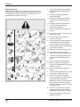
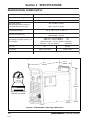
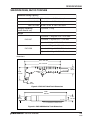
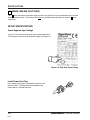
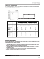
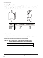
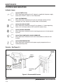


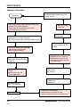
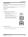
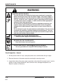
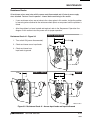
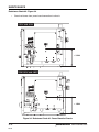

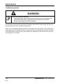
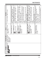
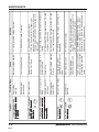

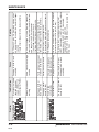


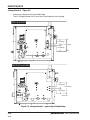

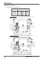
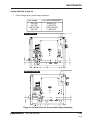

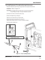
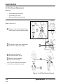
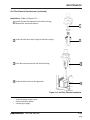
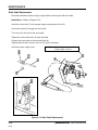
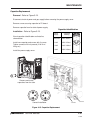

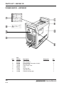
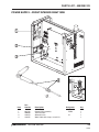
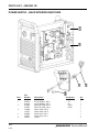

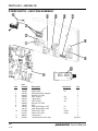


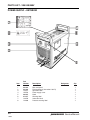
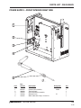
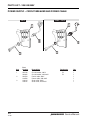

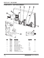


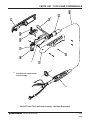


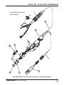


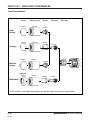


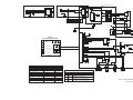


![PDF [1] - Dep SAE Soudage, Automatismes et Electronique location](http://vs1.manualzilla.com/store/data/005888267_1-8c649f384f0a877ffbc023ff9f75566c-150x150.png)