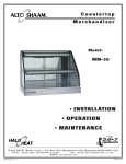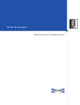
1
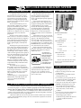
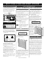
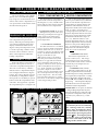
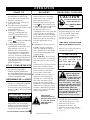
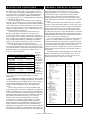
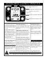
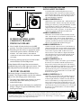
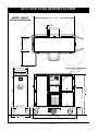
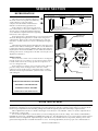
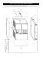
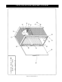
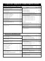
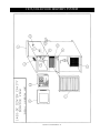
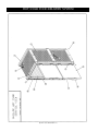
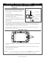
®
OPERATION and CARE MANUAL
HOT/COLD
F O O D D E L I V E RY S Y S T E M S
1400-DC/20
1400-DC/24
COOK/HOLD/SERVE SYSTEMS
W 1 6 4 N 9 2 2 1 Wa t e r S t r e e t
PHONE: 262.251.3800
800.558.8744
PRINTED IN U.S.A.
●
P. O . B o x 4 5 0
U . S . A ./ CANADA
●
Menomonee Falls , Wisconsin 53052-0450
FAX: 262.251.7067 • 800.329.8744 U . S . A ./ CANADA
262.251.1907 INTERNATIONAL DIVISION
U.S.A.
WEBSITE:
www.alto-shaam.com
#8900 •6/2001
HOT/COLD FOOD DELIVERY SYSTEM
SYSTEM DESCRIPTION
Food quality and service are more
important than ever in today’s institutional food service market. Alto-Shaam
recognizes this fact and developed the
Delivery Cart using the highest quality
stainless steel, insulating material, and the
finest workmanship.
The Alto-Shaam Delivery Cart is a
self-contained, complete hot/cold meal
preparation and delivery system. This
system is simple in concept and is
designed for any completely new delivery
method or for adaptation into any existing
institutional food service method of
preparation.
The heat source for the hot compartments consist of a resistance wire element.
This thermal cable element is wrapped in
exact configurations against the walls of
the heated compartments providing an
evenly applied, highly controlled, heat
input.
The design and operational characteristics of the ovens eliminate the need for a
heat circulating fan, thereby eliminating
the additional moisture loss associated
with that type of heat induction. Because
of the even heat application, the quality of
hot food is maintained for longer periods
of time. The actual time depends on the
type and quantity of product.
The refrigeration section of the
Delivery Cart utilizes a highly reliable
commercial refrigeration unit. The cold
compartment is fully insulated from the
heated sections.
Through the best arrangement of
the controls, operation of this appliance
is simplified. One power switch automatically energizes all functions. A variable
timer for each heated section automatically switches the oven mode from
holding to
a fixed reheating or cooking temperature.
With the timer in the OFF position, the
oven is at a reduced, fixed holding
temperature.
RECEIVING & UNPACKING
The Alto-Shaam Delivery Cart has
been thoroughly tested, checked for
proper calibration, and inspected to
ensure only the highest quality equipment
is provided.
Upon receipt of the Delivery Cart,
check the exterior of the shipping crate for
any physical damage that could result in
concealed damage to the contents.
Uncrate the unit carefully and inspect for
any shipping damage. Immediately
report any damage to the delivering
freight carrier. (See the Transportation
Damage and Claims section located in this
manual.)
If the Delivery Cart was not received
from the carrier in an upright position but
appears to be undamaged, carefully
restore the unit to the correct position as
soon as possible. The cart must remain in
an upright position for a minimum of 24
hours before use, to allow the compressor
oil to drain back into the crankcase.
Remove the uncrated unit from the
skid with a lift-truck or roll it off the skid
by means of the temporary ramp provided in the crate.
If a lift-truck is
used to remove the
Delivery Cart from
the skid, caution
should be used to
avoid damage to the
drive motor
assembly located
beneath the unit.
Save all the information and instructions packed inside the cart. Complete
and return the warranty card to the
factory as soon as possible to ensure
prompt service in the event of a warranty
parts or labor claim.
MODEL 1400-DC
HEATED COMPARTMENTS
SPILL PAN . . . . . . . . . . . . . . . . . . . . . . . . . . . 2 ea.
SIDE RACK
— 1" (25mm) Standoff . . . . . . . . . . . . . . . . . 4 ea.
COLD COMPARTMENT
Condensate Pan . . . . . . . . . . . . . . . . . . . . . . 1 ea.
SIDE RACK
— 1" (25mm) Standoff . . . . . . . . . . . . . . . . . 2 ea.
SIDE RACK
— 3" (76mm) Standoff . . . . . . . . . . . . . . . . . 1 ea.
TRAYS, HALF-SIZE
Model 1400-DC/20 . . . . . . . . . . . . . . . . . . 40 ea.
Model 1400-DC/24 . . . . . . . . . . . . . . . . . . 48 ea.
Check to ensure that all the above items
have been received as standard with each
Delivery Cart.
IMPORTANT SAFEGUARDS
●
●
●
●
●
EXTENDED STORAGE & BATTERY CHARGING
The Model 1400-DC with drive delivery cart contains rechargeable batteries that
were fully charged prior to shipment. Failure to properly store the unit and charge the
batteries will cause battery failure, and the battery warranty will become null and void.
Be sure to store delivery cart in a cool and dry location. If the cart will not be activated for service within 30 days of receipt, the batteries must be charged by connecting
the cord to electrical power for storage duration.
When removed from active service, the unit can remain continuously connected to
power to maintain full battery charge. Be sure to turn the Drive System Power Switch
OFF when not in use.
Operation & Care Manual #8900 • 1
●
●
●
Read this manual carefully before
operating the Delivery Cart.
Observe all safety precautions noted
in this manual.
The Delivery Cart should be used for
food preparation only.
Use caution to protect against the risk
of electric shock when operating in the
presence of water or other liquids.
Always move the unit to the workplace
BEFORE connecting the power cord.
This unit should not be operated in
an enclosed area, exposed to excessive
heat, steam, water, or other adverse
conditions.
For best service, the unit should be level.
Do not use cart if controls are not
functioning properly. Refer to
Trouble Shooting Guide in this manual
or contact an authorized service
technician.
HOT/COLD FOOD DELIVERY SYSTEM
ELECTRICAL INSTALLATION
The power specifications are
located on the Delivery Cart identification nameplate. This nameplate is
permanently attached to the cart and
must be located to determine and
verify power requirements.
EXAMPLE
SERIAL NUMBER & WARRANTY CODE
MAXIMUM RATED WATTAGE
ALTO-SHAAM IDENTIFICATION MODEL NUMBER
MODEL
1400-DC/XX
SERIAL NO.
VOLTS
X X X X -X X
~
XXX
REFRIGERANT
WATTS
XXXX
1 PH
XX
HZ
POUNDS
DESIGN PRESSURE
HI
LO
ALTO-SHAAM® INC. MILW. WI. PAT. NOS.
3521030
4595247
MAXIMUM RATED VOLTAGE
MAXIMUM RATED FREQUENCY
ENSURE THE POWER
SOURCE MATCHES THE
VOLTAGE STAMPED ON
THE UNIT NAMEPLATE
The unit is provided with a 10 ft.
(3048mm) electrical cord with plug. For
U.S. installation, the attachment plug
must be a NON-LOCKING, 30 ampere,
250 volt, 2-pole, 3-wire grounding plug
— NEMA 6-30P.
PLUG
C O L D C O M PA R T M E N T
For the best service, the unit should
be level. The Delivery Cart should not
be operated in an enclosed area, exposed
to excessive heat, steam, water, or any
other adverse conditions.
Clean the Delivery Cart thoroughly
before using. Wipe the exterior with a
clean damp cloth. Wash the interior, tray
racks, and trays with a mild soap
solution and rinse well.
The condensate pan is located on the
bottom of the refrigerated compartment,
just below the side rack with the 3"
(76mm) standoff.
The condensate pan size is:
The cold compartment door trim is
color coded with a blue, numbered
stripe. There are two types of Tray Side
Racks for the cold compartment —
2 with a 1" (25mm) standoff (same as the
heated compartments) and 1 with
a 3" (76mm) standoff.
The two side racks with the
1" (25mm) standoff must be installed in
the cold compartment toward the
outside (door-hinge side) of the compartment. Install the rack keyhole bracket
openings over the shoulder bolts. Push
down to lock in place.
NOTE: The condensate pan should be
checked for water after each
operation and emptied as
required.
HEATED COMPARTMENT
The heated compartment door trim is
color coded with red, numbered stripes.
HEATED COMPARTMENT
TRAY SIDE RACK
To install the Tray Side Racks in the
oven compartments, locate 4 racks with
the 1" (25mm) standoff.
G
6-30R
GENERAL INFORMATION
2-1/8" x 2-3/4" x 19-1/2"
(54mm x 70mm x 495mm)
CAUTION
RECEPTACLE
U N I T P R E PA R AT I O N
6-30P
BLACK WIRE
WHITE WIRE
=
=
L1
L2
GREEN WIRE
=
Equipment ground
The electrical outlets used for the
Delivery Cart must be properly
grounded in accordance with the
National Electrical Code and applicable
local codes.
Before plugging the unit in or
disconnecting it from the power source,
make certain the unit power switch is
in the OFF position. THE UNIT POWER
SWITCH IS LOCATED ON THE
CONTROL PANEL. The unit circuit
breaker should be in the ON [UP]
position.
Continue with “Preparation” and
follow the guidelines under “General
Operation” to assure the cart is functioning properly.
(25- 1"
mm
)
COLD COMPARTMENT
TRAY SIDE RACK
To install the tray side rack with the
3" (76mm) standoff in the cold compartment, position the keyhole openings in
the Tray Side
3
(7 6
-m m "
Racks over the
)
shoulder bolts
located on inside
(door latch side)
of the interior
cold compartment. Push
down to lock the
Tray Side Racks
into position.
AA
AA
AA
AA
AA
AA
INITIAL BATTERY CHARGE
The battery life expectancy is about
two years.
Before putting the delivery cart into
service the motor drive batteries must be
fully charged. Move the delivery cart to
the designated work area and connect the
unit to the power source for a minimum of
12 hours prior to use (S EE EXTENDED STORAGE
AND BATTERY CHARGING SECTION OF THIS MANUAL .)
Position the keyhole openings in the
Tray Side Racks over the shoulder bolts
located on the sides of the interior oven
compartments. Push down to lock the
Tray Side Racks into position.
Insert an oven Spill Pan directly
on the bottom surface of each oven
compartment.
Operation & Care Manual #8900 • 2
When connecting the delivery cart to
the power source, allow sufficient clearance for ventilation of the refrigerator air
vents located at the lower portion of the
cart, on both the control side and the
non-control side. The brake on the
motor drive as well as non-motorized
versions of the cart must be engaged at
all times unless it becomes necessary to
manually push the cart. (SEE SECTION TITLED
MOTOR DRIVE CONTROL FOR MORE INFORMATION .)
HOT/COLD FOOD DELIVERY SYSTEM
CIRCUIT BREAKERS
T E M P E R AT U R E C O N T R O L S
The circuit breaker for the 1400-DC
delivery cart is accessible through the
tray storage area located on the bottom
surface of the control compartment. For
cart operation the circuit breaker switch
must be in the ON position.
COLD COMPARTMENTS
HEATED COMPARTMENTS
The digital display will illuminate
and show the actual air temperature of
the refrigerator (cooler). Models with a
freezer will show the actual air temperature inside the freezer compartment.
Both cooking and holding temperatures are preset at the factory. When the
control for the heated compartments is
activated, the two digital displays will
illuminate and indicate the actual air
temperature inside each heated compartment. In order to reach the preset
cooking temperature, the timer for each
heated compartment must be activated.
The preset cooking temperature will be
maintained until the timer elapses to
zero (OFF). When the timer for each
heated compartment elapses to zero, the
heated compartments will automatically
decrease to the preset holding temperature. To maintain the preset holding
temperature in each heated compartment, do not activate the timers.
➾ R E F R I G E R AT O R 3 8 ° F ( 3 ° C )
TEMPERATURE D I S P L AY
Sensors controlling the temperature of
each compartment are preset at the
factory. When the preset temperatures
are reached, each digital temperature
display will fluctuate within several
degrees of the preset temperature. This
is a normal operating condition of the
electronic control and has no adverse
effect on the temperature within the
holding compartment.
C O N T R O L PA N E L
Each food delivery cart features an
electronic control panel to activate or
control the compartment temperatures.
The control can be factory ordered to
indicate interior compartment temperatures in degrees Fahrenheit or degrees
Celsius. The control offers the operator
the flexibility of independent compartment operation or the ability to operate
both hot and cold compartments at the
same time. Always preheat or prechill
all compartments prior to using the cart.
1400-DC
Refrigeration is preset at 38°F (3°C).
Following a prechill period of approximately one hour, the refrigeration
compartment will have reached the
preset temperature.
➾ AUTOMATIC DEFROST
The defrost function is a standard
control operation which automatically
initiates at the end of six (6) hours of
continuous operation in either the cold
mode or in the hot and cold mode. At
the start of the defrost cycle
" dFr" appears in the cooler display.
Defrost is preset at the factory and
timed for an approximate 35 minute
cycle. During this time period, all
compressor function ceases operation in
order to fully defrost the evaporator
coil. At the completion of the defrost
cycle, the compressor will resume
normal operation and quickly return
the cold compartment to the proper
preset temperature. The short time
period for defrosting has no significant effect on the internal temperature
of the refrigerated product.
CONTROL
COOLER
❄
PA N E L
COOKING TIME
▲
❄
▼
S TA N D A R D
D E L I V E RY
CARTS
MIN
▲
COOKING TIME
❄
OVEN TEMPERATURE
➾ COOKING 28 5°F (141 °C)
When the cooking timers are set, the
heated compartments will automatically
maintain the preset cooking (rethermalization/regeneration) temperature. Cooking
time is displayed in minutes and can be
increased ▲ , decreased ▼, or deactivated
by pressing .. The temperature displays
will indicate the actual air temperature
within the heated compartments.
PLEASE NOTE: As an option, an alternate
cooking/holding temperature may have
been preset by the factory when the order
was placed: cooking 265°F (129°C); holding 180°F (88°C), 170°F (76°C), or 160°F
(70°C).
CAUTION
OVEN TEMPERATURE
MIN
SPECIAL ORDER DELIVERY CARTS
▼COOKINGTEMPERATURE: ▼HOLDING TEMPERATURE:
265°F
(129°C)
➾ HOLDING 190°F (88°C)
The heated compartments are
preset at 190°F (88°C). Following a
preheating period of approximately
one hour, the heated cavities will have
reached the preset temperature for
holding hot foods.
180°F ; 170°F ; or 160°F
(82°C) (76°C) (70°C)
Operation & Care Manual #8900 • 3
To prevent the unit from being
accidentally deactivated during
the cooking mode the cooking
timers must be manually deactivated or must be allowed to cycle
to zero before pressing the power
OFF . Pressing the power
switch
switch OFF prior to deactivating
the timers will NOT result in any
change to the control status.
▼
O P E R AT I O N
S TA R T - U P
D E L I V E RY
Delivery carts are equipped with a 7.Use the Motor Drive Control to
motorized drive. Refer to the
transport the cart to the desigmotor drive control instructions
nated service area. (SEE MOTOR
DRIVE CONTROL OPERATION )
before moving the cart.
1. Connect the power cord into an
Before moving cart, turn power
appropriate outlet.
switch OFF. Disconnect power
2. Close the heated compartment
cord from the outlet and place the
vents located on the inside of each
cord in cord holder or endcompartment door.
brackets provided. Upon
3. Select mode of operation:
reaching the service area, plug the
● Press
for Refrigeration &
power cord into an appropriate
Freezer compartments (BLUE).
outlet and turn power switch ON.
● Press
Foods will be automatically mainfor Heated comparttained at proper serving temperaments (RED).
tures throughout the service
● Press
❄ for both Cold & Heated
period.
compartments (BLUE/RED).
❄
4. Preheat and prechill empty
compartments (without trays) for
approximately one hour. To
preheat to the cooking (RETHERMALIZE - REGENERATE ) temperature,
set the timers for a minimum of
one hour. Following a preheating
time period of approximately one
hour, the refrigerated and heated
compartments will have reached
preset temperatures.
L O A D C O M PA R T M E N T S
8.Assemble trays for meal service:
Extend U-shape, serving tray
shelves located in the center of
unit. Open the doors to both the
hot and cold compartments and
assemble meals.
FOR 1400-DC: Place serving
tray on shelf holder. Transfer hot
and cold half trays onto serving
tray.
For best service, all meals should
be served in a timely manner.
Following meal service turn the
power switch OFF and return
power cord to cord holder.
5. Load filled trays into appropriate
hot and cold compartments.
Products requiring maintenance
below refrigerated temperatures can
be stored in the freezer compartment 9.Use the Motor Drive Control to
of freezer equipped models.
transport cart to designated
cleaning area. Clean cart and
RETHERMALIZE or HOLD
trays after each meal service.
6. Reset timers for the appropriate
Follow the care and cleaning
amount of cooking time required
guidelines located in this manual.
to rethermalize (REGENERATE).
After each use, empty the water
Activate timers by pressing ▲ to
from the condensate pan located
increase or ▼ to decrease set time
in the lower section of the refrig( IN MINUTES ).
eration compartment.
TO RETHERMALIZE CHILLED MEALS
SET COOKING TIME: 60 MINUTES
TO RETHERMALIZE FROZEN MEALS
SET COOKING TIME: 105 MINUTES
1
HOUR ,
45
MINUTES
Following rethermalization, the
temperature will automatically
decrease and maintain the preset
holding temperatures until the
unit power switch is pressed OFF.
Cold food for
rethermalization or
reheating must never
be added to the unit
while hot food is
being held.
O P E R AT I N G C A U T I O N S
CAUTION
USE HAND PROTECTION
WHEN HANDLING
H OT C O M PA RT M E N T
ITEMS.
Do not use the cart if controls are
not functioning properly. Refer
to the Trouble Shooting Guide
located in this manual or
telephone an authorized
service technician.
TURN DRIVE SYSTEM POWER
SWITCH OFF WHEN NOT IN USE.
Observe all safety precautions
noted in this manual.
CAUTION
For proper sanitation, d o
n o t p u t s o i l e d trays
back into the cart
until all meals a r e
served.
The motor drive brake
must be engaged at
all times unless it
becomes necessary
to move the cart
manually. After moving t h e
c a r t m a n u a l l y , t h e wheels
of the cart and the motor drive
assembly will respond to even
a slight incline unless the
brake is reset. Maintaining a
"set" break to keep the cart in
a stationary position is an
i m p o r t a n t s a f e t y f a c t o r.
To keep drive batteries fully
charged, the cart must remain
connected to the power source
when not in service for a
maximum of 30 days. For
inactive periods longer than 30
days. SEE EXTENDED STORAGE SECTION IN
THIS MANUAL .
TO STOP OR RESET TIMERS, PRESS
Operation & Care Manual #8900 • 4
CLEANING and MAINTENANCE
CLEANING
A comprehensive
program of sanitation will
provide essential cleanliness.
This is important to build quality service as the
foundation of patient satisfaction.
Cleanliness, top operating efficiency and appearance of equipment
contribute considerably to savory,
appetizing food. The safest way to
ensure full natural food flavor is
through cleanliness. This means good
control of both visible soil (dirt) and
invisible soil (microorganisms).
Establishing a routine cleaning
and maintenance schedule will help
keep the hot/cold food delivery cart
running at top operating efficiency
and is an absolutely essential part of
a comprehensive sanitation program.
Good equipment maintained
and kept clean works better and
lasts longer. Protect your
investment.
Always follow appropriate local
health (hygiene) regulations regarding all applicable cleaning and sanitation requirements for equipment.
CAUTION
Always disconnect
the food delivery
cart from the
power source
before cleaning
or servicing.
TIRE MAINTENANCE
Tire pressure requires periodic
checking. Add air as required to
maintain a pressure level not to
exceed 60 pounds per square
inch (4 bars).
1. After disconnecting the delivery
cart from the power source, wipe
the power cord if necessary, and
insert it properly in the power
cord holder located along the
lower perimeter of the cart or the
external end-brackets provided.
2. Remove all trays, drip pans and
condensate pans. Wash these
items in the dishwasher. Rinse
well and let dry.
3. Clean all interior compartments
after each meal service. Any
spilled food should be removed
with a damp cloth and any good
alkaline or alkaline chlorinated
based commercial detergent or
grease solvent at the recommended strength. Use
a plastic scouring pad
or oven cleaner for
difficult areas. Avoid
the use of abrasive
cleaning compounds,
chloride based
cleaners, or cleaners
containing quaternary salts.
NOTE: Never use hydrochloric
acid (muriatic acid) on stainless
steel. Allow surfaces to air dry
for maximum effectiveness.
CAUTION
Do not steam clean the
exterior or interior of the unit.
Use caution to prevent
flooding the unit with water or
any liquid solution, particularly the electrical control
panel and motor areas.
Severe damage or electrical
hazard could result, voiding
the warranty.
Operation & Care Manual #8900 • 5
4. The refrigerator compartment
may be washed with a baking
soda (sodium bicarbonate)
solution. Use 3 tablespoons
(50 mil) of baking soda for each
quart (liter) of water.
5. To help maintain the protective
film coating on polished stainless
steel, clean the exterior of the
cabinet with a cleaner recommended for stainless steel. Spray
on a clean cloth and wipe with the
grain of the stainless steel.
6. To ensure proper air circulation,
the refrigeration condenser coil
grill must be periodically checked
and cleaned. Remove the vent
housing cover from the control
side of the cart. Brush or vacuum
the grill approximately once a
month or as soon as collection of
lint, dust, or dirt is observed at the
condenser. This is a very important maintenance procedure which
many times is overlooked.
Regular care and cleaning of the
coils will result in longer service of
the refrigeration unit and less
energy to operate.
7. All delivery cart door gaskets
are removable. To
maintain a good door
seal and to extend the
life of the gaskets,
periodically wash the
gaskets with warm
sudsy water. Always
rinse carefully to remove all
soap or detergent residue.
8. In the event the delivery cart is
out of operation for an extended
period of time, thoroughly clean
and sanitize the cart and clean
the door gaskets prior to use.
S A N I TAT I O N G U I D E L I N E S
GENERAL HOLDING GUIDELINE
Food flavor and aroma are usually so closely related that
it is difficult, if not impossible, to separate them. There is
also an important, inseparable relationship between cleanliness and food flavor. Cleanliness, top operating efficiency,
and appearance of equipment contribute considerably to
savory, appetizing foods. Good equipment that is kept clean,
works better and lasts longer.
Most food imparts its own particular aroma and many
foods also absorb existing odors. Unfortunately, during this
absorption, there is no distinction between GOOD and BAD
odors. The majority of objectionable flavors and odors troubling food service operations are caused by bacteria growth.
Sourness, rancidity, mustiness, stale or other OFF flavors are
usually the result of germ activity.
The easiest way to insure full, natural food flavor is
through comprehensive cleanliness. This means good
control of both visible soil (dirt) and invisible soil (germs). A
thorough approach to sanitation will provide essential cleanliness. It will assure an attractive appearance of equipment,
along with maximum efficiency and utility. More importantly, a good sanitation program provides one of the key
elements in the prevention of food-borne illnesses.
A controlled holding environment for prepared foods is
just one of the important factors involved in the prevention
of food-borne illnesses. Temperature monitoring and control
during receiving, storage, preparation, and the service of
foods are of equal importance.
The most
accurate
I N T E R N A L F O O D P R O D U C T T E M P E R AT U R E S
method of
HOT FOODS
measuring
DANGER ZONE
40° TO 140°F
(4° TO 60°C)
safe temperaCRITICAL ZONE
70° TO 120°F
(21° TO 49°C)
SAFE ZONE
140° TO 165°F
(60° TO 74°C)
tures of both
hot and cold
COLD FOODS
DANGER ZONE
ABOVE 40°F
(ABOVE 4°C)
foods is by
SAFE ZONE
36°F TO 40°F
(2°C TO 4°C)
internal
FROZEN FOODS
product
DANGER ZONE
ABOVE 32°F
(ABOVE 0°C)
temperature.
CRITICAL ZONE
0° TO 32°F
(-18° TO 0°C)
A quality
SAFE ZONE
0°F OR BELOW
(-18°C OR BELOW)
thermometer
is an effective tool for this purpose, and should be routinely
used on all products that require holding at a specific
temperature.
A comprehensive sanitation program should focus on the
training of staff in basic sanitation procedures. This includes
personal hygiene, proper handling of raw foods, cooking to a
safe internal product temperature, and the routine monitoring of internal temperatures from receiving through
service.
Most food-borne illnesses can be prevented through
proper temperature control and a comprehensive program of
sanitation. Both these factors are important to build quality
service as the foundation of customer satisfaction. Safe food
handling practices to prevent food-borne illness is of critical
importance to the health and safety of your customers.
HACCP, an acronym for Hazard Analysis (at) Critical
Control Points, is a quality control program of operating
procedures to assure food integrity, quality, and safety.
Taking steps necessary to augment food safety practices are
both cost effective and relatively simple. While HACCP
guidelines go far beyond the scope of this manual, additional
information is available by contacting the USDA/FDA Foodborne Illness Education Information Center at (301)504-6803.
Chefs, cooks and other specialized food service
personnel employ varied methods of cooking. Proper
holding temperatures for a specific food product must be
based on the moisture content of the product, product
density, volume, and proper serving temperatures. Safe
holding temperatures must also be correlated with palatability in determining the length of holding time for a specific
product.
Halo Heat maintains the maximum amount of product
moisture content without the addition of water, water vapor,
or steam. Maintaining maximum natural product moisture
preserves the natural flavor of the product and provides a
more genuine taste. In addition to product moisture retention, the gentle properties of Halo Heat maintain a consistent
temperature throughout the cabinet without the necessity of
a heat distribution fan, thereby preventing further moisture
loss due to evaporation or dehydration.
In an enclosed holding environment, too much moisture
content is a condition which can be relieved. A product
achieving extremely high temperatures in preparation must
be allowed to decrease in temperature before being placed in
a controlled holding atmosphere. If the product is not
allowed to decrease in temperature, excessive condensation
will form increasing the moisture content on the outside of
the product.
Most Halo Heat Holding Equipment is provided with a
thermostat control between 60° and 200°F (16° to 93°C). If
the unit is equipped with vents, close the vents for moist
holding and open the vents for crisp holding.
H O L D I N G T E M P E R AT U R E R A N G E
MEAT
BEEF ROAST — Rare
BEEF ROAST — Med/Well Done
BEEF BRISKET
CORN BEEF
PASTRAMI
PRIME RIB — Rare
STEAKS — Broiled/Fried
RIBS — Beef or Pork
VEAL
HAM
PORK
LAMB
POULTRY
CHICKEN — Fried/Baked
DUCK
TURKEY
GENERAL
FISH/SEAFOOD
FISH — Baked/Fried
LOBSTER
SHRIMP — Fried
BAKED GOODS
BREADS/ROLLS
MISCELLANEOUS
CASSEROLES
DOUGH — Proofing
EGGS —Fried
FROZEN ENTREES
HORS D'OEUVRES
PASTA
PIZZA
POTATOES
PLATED MEALS
SAUCES
SOUP
VEGETABLES
FA H R E N H E I T
CELSIUS
140°F
160°F
160° — 175°F
160° — 175°F
160° — 175°F
140°F
140° — 160°F
160°F
160° — 175°F
160° — 175°F
160° — 175°F
160° — 175°F
60°C
71°C
71° — 79°C
71° — 79°C
71° — 79°C
60°C
60° — 71°C
71°C
71° — 79°C
71° — 79°C
71° — 79°C
71° — 79°C
160°
160°
160°
160°
71°
71°
71°
71°
—
—
—
—
175°F
175°F
175°F
175°F
79°C
79°C
79°C
79°C
160° — 175°F
160° — 175°F
160° — 175°F
71° — 79°C
71° — 79°C
71° — 79°C
120° — 140°F
49° — 60°C
160° — 175°F
80° — 100°F
150° — 160°F
160° — 175°F
160° — 180°F
160° — 180°F
160° — 180°F
180°F
180°F
140° — 200°F
140° — 200°F
160° — 175°F
71°
27°
66°
71°
71°
71°
71°
— 79°C
— 38°C
— 71°C
— 79°C
— 82°C
— 82°C
— 82°C
82°C
82°C
60° — 93°C
60° — 93°C
71° — 79°C
The holding temperatures listed are suggested guidelines.
Operation & Care Manual #8900 • 6
—
—
—
—
MOTOR DRIVE CONTROL OPERATION
FAST/SLOW SPEED SWITCH ( YELLOW )
ON/OFF POWER SWITCH
( BLUE )
REVERSE DRIVE CONTROL BUTTONS
EMERGENCY STOP BUTTON
( RED )
EMERGENCY STOP
BATTERY
LOW
BATTERY CHARGE INDICATOR LIGHTS
FULL
®
FORWARD DRIVE CONTROL BUTTONS
MOTOR DRIVE CONTROL
A two-speed Motor Drive Control is
located at both ends of the cart to
propel the unit in both forward and
reverse. Slow speed is 0.9 mph (1.4
km/hr) and fast speed is 1.9 mph
(3.1 km/hr).
REVERSE DRIVE
CONTROL BUTTONS
The reverse drive control buttons are
located toward the top of the drive control
housing. Pressing either of these buttons
will move the cart in reverse or away from
the operator.
ON/OFF POWER SWITCH
The ON/OFF power switch (BLUE)
controls the Motor Drive Control
and is located at the top of the drive
control housing at one end of the
cart only. To engage the drive
control press the ON/OFF power
switch to the "ON" position. Allow
2 to 3 seconds for control to
initialize before using
Forward/Reverse Control buttons.
EMERGENCY STOP BUTTON
When pushed, the red emergency stop
button completely disengages the motor
drive control and will immediately halt all
cart movement. To restore motor drive
function, turn and release the emergency
stop button in a clockwise direction.
FAST/SLOW SPEED SWITCH
The yellow FAST/SLOW speed
switch is located left of the
ON/OFF Power Switch. To engage
Fast Speed, depress the yellow
switch – the switch will illuminate.
For best results, start in Slow Speed.
The cart will accelerate to speed
within 3 to 4 seconds. Once cart is
moving – engage Fast Speed. This
will minimize cart “surge”.
BATTERY INDICATOR LIGHTS
When the motor drive control switch is in
the "ON" position, a battery light will illuminate indicating the condition of the battery
charge: RED , low; YELLOW, medium; or
GREEN , full . To recharge the battery when
indicating a medium or low charge,
connect the cart to the power source until
the charge is restored (one hour minimum).
If battery charge is insufficient to maintain
the cart through the service period or while
en route, the motor drive assembly brake
must be released and the cart manually
moved to a power source. ( SEE SECTION TITLED
F O R WA R D D R I V E
CONTROL BUTTONS
The forward drive control buttons
are located toward the bottom of
the drive control housing. Pressing
either of these buttons will move
the cart forward or toward the
operator.
MOTION BEEPER, HORN
There is an audible signal whenever
the drive control is engaged in either
a forward or reverse motion.
IMPORTANT
FOR THE SAFEST METHOD
OF OPERATION, A CART
OPERATOR SHOULD ALWAYS
BE POSITIONED AT THE
FRONT OF THE CART IN
WHICHEVER DIRECTION THE
CART IS MOVING.
MOTOR DRIVE FOR DETAILED INSTRUCTIONS .)
A S A S A F E T Y P R E C A U T I O N D O N O T G U I D E C A RT F R O M T H E B A C K .
GUIDE THE UNIT TO DESTINATION BY PULLING FROM EITHER END OF THE CART.
To keep drive batteries fully charged, the cart must remain connected to the power source
when not in service. Turn drive system power switch OFF when not in use.
Operation & Care Manual #8900 • 7
MOTOR
DRIVE
BRAKE
The motor drive brake must be
engaged at all times unless it
becomes necessary to move
the cart m a n u a l l y. A f t e r
moving the cart manually,
the wheels of the cart and
the motor drive assembly will respond
to even a slight incline unless the brake
is reset. Maintaining a "set" brake to
keep the cart in a stationary position is
an important safety factor.
IF DRIVE
BATTERY
LOSES
➱
CHARGE
IN
TRANSIT
1. Move handle of brake clockwise to the OFF position.
2. Position an operator at the front to guide the cart while
another operator manually pushes from the back.
3. Move the cart to an appropriate outlet and connect power
cord for a minimum of 30 minutes. For a full charge, cart
must be connected to the power source for a minimum
of 1 hour.
4. Following recharge period, make certain the brake
handle has been turned counter-clockwise to the on
position and continue cart use.
ALWAYS OBSERVE THE MOTOR DRIVE BRAKE
SAFETY PRECAUTIONS.
—
DISENGAGE
BRAKE
EXTENDED STORAGE: When removed from active service, the
unit can remain continuously connected to power up to a
maximum of 30 days to maintain full battery charge. Turn the
Drive System Power Switch OFF when not in use. See Extended
Storage & Battery Charging section of this manual.
Operation & Care Manual #8900 • 8
CART FREEWHEELING and
DRIVE SAFETY FEATURES
MOTOR DRIVE BRAKE
AA
AA
OFF
17
ON
18
BRAKE HANDLE
To freewheel the cart manually, the Drive Power
Switch must be OFF – then the Drive Brake must be
placed in the OFF position. See Drive Brake Caution
below. Restore the Drive Brake to the ON position
upon freewheeling completion.
ALARM CONDITION No. 1
19
20
DRIVE BRAKE
With the Drive Power Switch ON – and then the Drive
Brake turned OFF – the drive unit provides dynamic
braking (movement is possible, but difficult). If either
Forward/Reverse Drive Control Buttons are
depressed, the motion beeper will sound an alarm and
the Drive Motor will not operate. To clear the alarm
and restore operation, turn the Drive Brake ON.
ALARM CONDITION No. 2
If the Drive Power Switch and Drive Brake are both
OFF – then the Drive Power Switch is turned ON, the
motion beeper will sound an alarm and the drive
motor will not operate. To clear the alarm and restore
operation, turn the Drive Brake ON, then turn the
Drive Power Switch OFF and then ON again.
IF DRIVE BATTERY LOSES
CHARGE IN TRANSIT,
DISENGAGE BRAKE
ALARM CONDITION No. 3
1. Move handle of brake clockwise to the OFF
position. Turn Drive System Power Switch OFF.
2. Manually push the cart to an appropriate outlet
and connect power cord for a minimum of 30
minutes. FOR A FULL CHARGE, CART MUST BE
CONNECTED TO THE POWER SOURCE FOR A MINIMUM
OF
1 HOUR.
3. Following recharge period, move brake handle
counter-clockwise to the ON position.
To keep batteries fully charged, the cart must remain
connected to the power source when not in service. Turn
Drive System Power Switch OFF when not in use.
BATTERY CHARGER
The battery charger is located on the Motor Drive
Assembly. The charger includes one bi-color indicator
light to show the charging state of the battery.
A. The yellow light indicates the charger is in operation but the motor drive battery has not yet
reached full charge.
B. A green light indicates the battery has reached full
charge. Charger can operate indefinitely without
harming the battery.
If either Forward or Reverse Drive Control Button is
depressed and the Drive Power Switch is turned ON,
the motion beeper will sound an alarm and the drive
motor will not operate - OR - if either Forward or
Reverse Drive Control Button is depressed immediately after the Drive Power Switch is turned on, the
motion beeper will sound an alarm and the drive
motor will not operate.
ALARM CONDITION No. 4
If the cart power cord is connected to power and then
the Drive Power Switch is turned ON, the motion
beeper will sound an alarm, the green “full” battery
indicator light will flash, and the drive motor will not
operate. To clear the alarm and restore operation,
disconnect the cart power cord from the power supply;
turn the Drive Power Switch OFF for 5 seconds and
then turn it ON again.
ALARM CONDITION No. 5
If the Drive Power Switch is ON, and the cart power
cord is connected to power, the green “full” battery
indicator light will flash. If either Forward/Reverse
Drive Control Button(s) are depressed, the motion
beeper will sound an alarm and the drive motor will
not operate. To clear the alarm and restore operation,
disconnect the cart power from the power source; turn
the Drive Power Switch OFF for 5 seconds and then
turn it ON again.
Drive Brake • Caution
The motor drive brake must be engaged at all times unless it becomes necessary
to move the cart manually. After moving the cart manually, the wheels of the cart and the motor drive
assembly will respond to even a slight incline unless the brake is reset. Maintaining a "set" brake to keep the
cart in a stationary position is an important safety factor.
Operation & Care Manual #8900 • 9
HOT/COLD FOOD DELIVERY SYSTEM
MODEL 1400-DC
62-3/4" (1594mm)
EXTERIOR DIMENSIONS
23-1/2"
(597mm)
20-1/4"
(514mm)
14-1/4"
(514mm)
23-1/2" (597mm)
FULL-SIZE TRAY STORAGE AREA
20-1/4" (514mm)
15-15/16" Wide x 8-3/4" High
(405mm x 222mm)
1
COOLER
COOKING TIME
1
OVEN TEMPERATURE
®
❄
▲
❄
❄
2
MIN
▲
COOKING TIME
OVEN TEMPERATURE
MIN
2
®
EMERGENCY STOP
BATTERY
LOW
3
3
4
4
5
5
6
6
7
7
8
8
9
9
10
10
11
11
12
12
FULL
30"
(762mm)
68-3/4"
(1746mm)
Operation & Care Manual #8900 • 10
60-5/8"
(1047mm)
41-1/4"
11"
(279mm)
Electrical Cord
(1540mm)
®
SERVICE SECTION
The primary purpose of the service section of this manual is to provide the service technician with helpful
information regarding basic service to the Alto-Shaam Delivery Cart. It is not intended to be a refrigeration or
heating system textbook. For detailed compressor or condenser information, consult the Copeland Service
Manuals. For major repairs to the Delivery Cart, contact an authorized service facility or the factory.
T E M P E R AT U R E C A L I B R AT I O N
OVEN COMPARTMENTS
The oven thermostat is part of the
electronic control, therefore, no adjustment or calibration is ever necessary.
The fixed temperatures for both
cooking (reheating) and holding are
determined at the time of order and
are set as standard or special order at
the temperatures indicated in the
section titled Temperature Controls,
Heated Compartments
C O L D C O M PA R T M E N T
The refrigerator thermostat is preset
at the factory and should not require
adjustment.
REFRIGERATOR
38°F (3.3°C)
If it appears the refrigerator thermostat requires adjustment, contact the
factory or an authorized factory service
agency.
SENSORS
Sensors for the oven compartments
and the refrigerator compartment are
mounted on the side wall of each
respective compartment, behind the
tray side racks
To verify the actual compartment
temperature with the temperature
indicated on the digital display of the
control panel, check the air temperature within the compartment with a
quality thermal indicator.
1.
Make certain all sensors are clean
and undamaged.
2.
Load the empty trays into each
compartment.
3.
Position the end of the thermal
indicator to be used for testing in
the center of the compartment to
be tested. On 1400-DC/20 models,
placement is between the 2nd
and 3rd tray. Placement for
1400-DC/24 models is between
the 3rd and 4th tray.
4.
Allow one (1) hour for the compartment temperature to stabilize before
comparing the digital display on the
control panel with the thermal indicator. Do not open the compartment
doors during this test procedure.
NOTE: The compartment
temperatures indicated on
the digital display of the
unit control panel will
continuously
fluctuate
within several degrees of the
fixed compartment temperatures.
THIS IS A NORMAL
O P E R AT I N G C O N D I T I O N . T h e
mid point between the high
and low reading should be
considered as the actual
compartment temperature.
If the temperature on the thermal
indicator does not match the digital
display for that compartment, the fault
may lie in the sensors, sensor wiring, or
electronic control.
To check the sensors, test the resistance with a quality ohm meter on the
low-ohms scale. Take the reading at the
sensor connections. Remove the sensor
and place in an ice water bath (32°F or
0°C). The resistance should be approximately 100 ohms.
CIRCUIT BREAKER
The circuit breaker for the 1400-DC
delivery cart is accessible through the
tray storage area located on the bottom
surface of the control compartment. For
cart operation the circuit breaker switch
must be in the ON position.
The current draw should be checked
with an amp meter and the reading
compared with the unit electrical rating.
The reading on the amp meter should not
exceed 30 amps. If the amp meter indicates a correct reading, the circuit breaker
is defective and must be replaced.
H E AT I N G E L E M E N T S
Element lead wires can be accessed
at the terminal block located behind the
electronic control box. Continuity of the
cable heating elements should be
checked with an ohm meter from each
element to ground. THERE SHOULD
BE NO CONTINUITY TO GROUND.
If there is continuity to ground, replace
the shorted element.
Check the resistance of each element
separately. Cable resistance is approximately .66 ohms/foot (305mm). The
resistance should measure between 18.9
and 22.0 ohms. If the element resistance
is very high or low, replace the defective
length of element.
If only one length of cable requires
replacement, check the other element for
signs of deterioration and replace at the
same time.
ELECTRONIC CONTROL
CAUTION
ALWAYS DISCONNECT
THE FOOD
DELIVERY CART FROM THE
POWER SOURCE BEFORE
CLEANING OR SERVICING.
Operation & Care Manual #8900 • 11
Before attempting to replace the
electronic control, make certain the
problem is in the control and not in
another area of the unit. Check all
other items listed in the Service
Section of this manual. If all is in
order, check to make certain electrical
power is reaching the control and that
the control inter-connectors are secure.
For major repairs, contact an authorized service facility or the factory.
SERVICE SECTION
1400-DC ELECTRONIC CONTROL REPLACEMENT INSTRUCT I O N S
A.C. POWER CORD
FUSE (2) 5 x 20mm
250MA/250V SLO BLO
RELAY
POWER
MODULE
SENSOR
CONNECTOR
DB9(F)
RELAY SSR
CONNECTOR
1 4 0 0 - D C C O N T R O L PA N E L
REAR VIEW
1.
Press the power switch on the
Delivery Cart control panel to
the OFF position.
2.
Disconnect the electrical power
cord from the power source.
3.
Remove the glass control panel
door on models so equipped.
Fully open door and lift up to
disengage hinges.
4.
5.
6.
7.
8.
Check the model number
located on the top of the
control and compare it with
the replacement control to
assure compatibility.
9.
Remove old control from unit.
10.
Install the new control in the
reverse order. Use caution
when handling the new
control to prevent damage to
the keypad or the overlay
panel surface.
Remove the four (4)
mounting screws at the front of
the control.
Carefully move the control
forward, as far as the
connecting wires will allow.
Remove the A.C. power cord
on the control by pulling up on
the plug.
Loosen the two (2) side
mounting screws on the sensor
connector. Unplug the sensor
connector at the back of the
control.
11.
12.
13.
Do not over-tighten the two
sensor or relay connector sidemounting screws.
Caution must be used when
installing the new control to
prevent pinching, nicking, or
cutting the connection wires.
Check the function of the
replacement control by operating the delivery cart
according the the General
Operating Instructions.
Operation & Care Manual #8900 • 12
14.
These instructions are
intended for the replacement
of controls of the same type
and model. Special instructions are required for retrofitting an electronic timer
control in place of a control
with a rotating timer.
CAUTION
ALWAYS DISCONNECT
FOOD DELIVERY CART
FROM THE POWER
SOURCE BEFORE
CLEANING OR SERVICING.
SERVICE SECTION
R E F R I G E R AT I O N
➠
➠
C O M P R E S S O R M O D E L N U M B E R N O M E N C L AT U R E
XXXX
- XXXX
XXX
XXX
The only source for complete compressor
PRODUCT VARIATIONS
information is the serial plate located directly
ELECTRICAL CODES
on the compressor. The serial plate
COMPRESSOR MOTOR PROTECTION
COMPRESSOR MOTOR TYPE
compressor model number nomenclature is
COMPRESSOR MOTOR RATING (NOMINAL)
indicative of the following specifications:
MODEL VARIATIONS
If the compressor does not start, starts and
DISPLACEMENT AND VALVE PLATE
COMPRESSOR COOLING (TANDEM STYLE MODELS)
runs continuously or short-cycles and there are no
COMPRESSOR FAMILY SERIES
obvious causes, consult the Copeland Compressor
Service Manual for helpful information regarding
full service to the compressor.
EVAPORATOR COIL
If the refrigerator compartment does not reach temperature,
(A/S RE-22404)
check the Refrigerant Sight Glass located in the refrigerator
compartment. Remove the cold compartment tray side rack
with the 3” (76mm) return for access to the Refrigerant Sight
Glass.
SIGHT PORT COVER
When the unit is fully charged, the sight glass will appear clear
and the center indicator will be green. If there is a leak and the line
DRY (green)
REFRIGERANT
is empty, the sight glass will have bubbles and the center indicator
FULLY CHARGED
may be yellow. If consistent bubbles are seen while the machine is
DRY
running, unit is short of refrigerant or the TXV valve may be out of
adjustment or defective..
SPORLAN
MODEL 1400-DC
The cooler uses a TXV valve to meter the flow of refrigerant
into the evaporator coil. There is a low pressure safety switch
located in the suction line to help protect the compressor in
case of a refrigerant leak.
If the compressor will not start, locate the leads of the low
pressure safety switch and bypass the connection. If the
compressor starts at this point, a refrigerant leak is evident.
This leak must be repaired and the system must be evacuated
and recharged.
CAUTION
WET
WET (yellow)
REFRIGERANT LOW
EXCESSIVE MOISTURE
SIGHT GLASS
(A/S RE-22589)
REFRIGERANT SIGHT GLASS
ALWAYS DISCONNECT THE FOOD
DELIVERY CART FROM THE
POWER SOURCE BEFORE
CLEANING OR SERVICING.
DOOR ADJUSTMENT
The doors on all compartments of the delivery cart have been adjusted at the factory to provide a proper seal. Routine
maintenance of the delivery cart should include a periodic examination of the door gasket to make certain a good seal is maintained. Proper adjustment can be tested by pulling a dollar bill through the gasket seal and feeling a slight resistance.
Minor adjustment to the doors is made at the hinges in one direction — IN and OUT. There is no need to adjust the doors
up-and-down, or side-to-side.
For in-and-out adjustment, loosen the three (3) screws holding the plate to the door hinge. Move the door OUTWARD to
LOOSEN the gasket seal or INWARD to TIGHTEN the gasket seal. The adjustment faces are grooved so that movement is fixed
when the screws are retightened. Adjust the hinges so that the door face and the unit face are parallel, and the portion of the
gasket at the hinge-side does not bind when the door closes. Following adjustment, retest for proper seal as indicated above.
Operation & Care Manual #8900 • 13
HOT/COLD FOOD DELIVERY SYSTEM
TROUBLE SHOOTING GUIDE
PROBLEM
Dietary Cart does not operate
Compressor does not operate —
all other functions operate
Circuit breaker trips
Compressor operates too long
or operates continuously
POSSIBLE CAUSE
REMEDY
1.
2.
3.
4.
5.
No electrical power
Defective cord or plug
Circuit breaker tripped
Power switch defective
Defective control
Check power source
Repair or replace
Reset
Replace
Replace
1.
2.
3.
4.
5.
6.
Blown fuse
Low voltage
Faulty circuit
Defective compressor
Defective control
Defective transformer
Replace fuse
Check power source
Check circuitry
Replace
Replace
Replace
1.
2.
3.
4.
5.
6.
7.
8.
Power source not matched to unit
Faulty wiring
Breaker defective
Refrigeration unit defective
Compressor overheating
Compressor motor shorted
Heating element shorted
Defective control
Relocate unit to proper power source
Repair
Replace
Repair or replace
Check refrigeration system
Replace compressor
Replace
Replace
1.
2.
3.
4.
5.
6.
7.
8.
Defective evaporator blower motor
Condenser dirty
Exhaust fan not operating
Air vents restricted
Excessive load in refrigerator
Evaporator iced due to continuous operation
Refrigeration system faulty
Low refrigerant (bubbles in sight-glass)
Replace evaporator blower motor
Clean condenser coil and grill
Replace
Allow adequate ventilation space
Follow prescribed procedures
Shut unit OFF to deice
Repair or replace
Charge system
Compressor operates in short cycles
1. Refrigeration system faulty
2. Defective sensor(s)
3. Control too hot
Repair or replace
Replace
Check cooling fan for obstruction
Refrigerator not maintaining
temperature
1.
2.
3.
4.
5.
6.
Door seals
Fan not operating
Bent or defective sensor
Refrigeration system faulty
Defective Control
Low refrigerant
Adjust doors — Clean or replace gasket
Replace
Replace
Repair or replace
Repair or replace
Recharge compressor
Unit not reheating or holding properly
1.
2.
3.
4.
5.
6.
7.
8.
Power source not matched to unit
Operating procedure
Heating element open or shorted
Loose door seals
Oven sensor dirty
Oven sensor defective
Control defective
Bent or defective sensors
Relocate unit to proper power source
Check and follow prescribed guidelines
Replace
Adjust doors
Clean
Replace
Replace
Replace
Inaccurate temperature display
1. Sensor wiring faulty
2. Bent or defective sensors
3. Control faulty
Repair
Replace
Replace
1. Hot cavity sensor short circuited
2. Hot cavity sensor open
Cavity temperature exceeds 360°F (182°C)
— Defective sensor
— Shorted Power Module
Repair or replace sensor
Repair or replace sensor
Replace sensor
Replace Power Module
1. Cold cavity sensor short circuited
Shorted Power Module
2. Cold cavity sensor open
Repair or replace sensor
Replace Power Module
Replace sensor
1. Freezer sensor open
Defective compressor
2. Cold cavity sensor short circuited
Shorted Power Module
Repair or replace sensor
Repair or replace sensor
Repair or replace sensor
Replace Power Module
Display Error Message - Hot Compartments
1. SenS
2. Hot
Display Error Message - Cold Compartment
1. Cld
2. Hi
Display Error Message - Freezer
1. Hi
2. -8°F (-22°C)
Operation & Care Manual #8900 • 14
1 4 0 0 - D C S E R V I C E V I E W PA R T S L I S T S
1400-DC/20 & 1400-DC/24 SERVICE VIEW
DESCRIPTION
QUANTITY
1. TOP ASSEMBLY
— TOP MOUNTING SCREWS
2. PERIMETER BASE ASSEMBLY, includes
1-12-00
PART NUMBER
1
5949
2
SC-2425
1
4310
— BUMPER
1
BM-22417
— BASE WELD ASSEMBLY
1
14886
— PERIMETER TUBE ASSEMBLY
1
14716
3. SWIVEL CASTERS
4
CS-22028
4. MOTORIZED DRIVE SYSTEM
1
MO-33514
— CASTER & MOTOR MOUNTING SCREWS
16
SC-22422
— CASTER & MOTOR MOUNTING WASHERS
16
WS-2867
— CASTER & MOTOR MOUNTING NUTS
16
NU-2866
4
HD-22257
8
SC-22339
DESCRIPTION
QUANTITY
6. COLD END PANEL
— SMALL CARD HOLDERS (not shown)
PART NUMBER
1
14097
2
12285
1
TA-22418
— CARD HOLDER MOUNTING ADHESIVE
LENGTH: 32” (812mm)
7. HOT END PANEL
1
11986
2
SC-2425
—
—
—
—
S E E H O T T U B E PA R T S L I S T
—
—
DESCRIPTION
QUANTITY
— END PANEL MOUNTING SCREWS
8. COLD TUBE SECTION
5. “U” HANDLE
— “U” HANDLE MOUNTING SCREWS
—
S E E C O L D T U B E PA R T S L I S T
9. CENTER CAVITY SECTION
—
S E E C E N T E R S E C T I O N PA R T S L I S T
10. HOT TUBE SECTION
—
1400-DC COLD TUBE SERVICE VIEW
DESCRIPTION
QUANTITY
5/21/99
PART NUMBER
PART NUMBER
1. COLD TUBE ASSEMBLY (1 phase)
1
5953
10. COLD DOOR
2
5947
COLD TUBE ASSEMBLY (3 phase)
1
5970
INSULATION
2
13077
2
HD-2565
2
13078
HANDLE MOUNTING SCREWS
8
SC-2073
INSULATION, SIDE
2
13079
HANDLE LATCH PLATE MOUNTING SCREWS
4
SC-2070
INSULATION STUDS
4
ST-23143
HANDLE INSULATION SLEEVE
2
SL-2642
INSULATION CUPS
4
CL-22259
3
HG-22338
3. CORD (1 ph): 10’ (3048mm)
1
CD-3304
HINGE TO UNIT MOUNTING SCREWS
18
SC-2713
CORD (3 ph): 10’ (3048mm)
1
CD-3727
HINGE TO DOOR MOUNTING SCREWS
18
SC-2072
2
GS-23407
—
INCLUDES ITEMS
2
THROUGH
8
11. COLD DOOR HANDLE
2 INSULATION
12. COLD DOOR HINGE (1 pair per part number)
4. FAN
1
FA-3861
1
SC-22268
5. SENSOR
1
SN-33541
6. EVAPORATOR
1
RE-22404
4
SC-2332
1
11939
4
SC-2332
FAN MOUNTING SCREWS
EVAPORATOR MOUNTING SCREWS
7. FAN SHROUD
FAN SHROUD MOUNTING SCREWS
8. SIDE RACK MOUNTING STUDS
9. COLD TUBE TO BASE MOUNTING SCREWS
COLD TUBE TO BASE MOUNTING WASHERS
16
ST-2546
4
SC-22796
4
WS-2867
13. COLD DOOR GASKET
14. DC/20 COLD TUBE NUMBER DECAL (blue-4 pcs)
1
PE-22399
DC/24 COLD TUBE NUMBER DECAL (blue- 4 pcs)
1
PE-22401
15. CORD PLUG (1 ph)
1
PG-3735
16. DRIP PAN ASSEMBLY
1
4824
17. DC/20 FAN SIDE RACK
1
4338
DC/24 FAN SIDE RACK
1
4345
18. DC/20 SMALL SIDE RACK
2
11938
19. DC/24 SMALL SIDE RACK
2
11992
1400-DC REFRIGERATION SPECIFICATIONS
COMPRESSOR: . . . . . . . . . . . . . . . . . . . . . . . . 1/2 HP
Rated capacity (BTU/HR)
Voltage (nominal)
. . . . . . . . . . . . . . . . . . . 3600
. . . . . . . . . . . . . . . . . . . . . . . . 115
Hertz/Phase . . . . . . . . . . . . . . . . . . . . . . 60 Hz/1 Ph
Rated Load Amps (RLA) . . . . . . . . . . . . . . . . . . . . . 6.6
Thermally Protected Amps (LRA) . . . . . . . . . . . . . . . 29.0
Refrigerant . . . . . . . . . . . . . . . . . . . . . . . . . . R 4 0 4 A
Design Pressure (PSIG): . . . . . . . . . . . . . . L o w S i d e 150
. . . . . . . . . . . . . . . . . . . . . . . . . . . H i g h S i d e 235
CAPACITIES:
Refrigerator Charge (pounds)
. . . . . . . . . . . . . . . . . 1.80
Oil Charge (ounces) . . . . . . . . . . . . . . . . . . . . . . . . 16
EVAPORATOR FAN:
Voltage/Wattage/Hertz . . . . . . . . . . . . . 230V/70W/60 Hz
AIR CFM
. . . . . . . . . . . . . . . . . . . . . . . . . . . . . 240
LIQUID LINE FILTER DRIER:
Flow Capacity (TONS) . . . . . . . . . . . . . . . . . . . . . . 2.1
TEMPERATURE CONTROLS:
Refrigeration Range . . . . 37°F
Operation & Care Manual #8900 • 15
MEAN
33°to 40°F ( C . +0,56° to 4°C)
HOT/COLD FOOD DELIVERY SYSTEM
Operation & Care Manual #8900 • 16
HOT/COLD FOOD DELIVERY SYSTEM
Operation & Care Manual #8900 • 17
1 4 0 0 - D C S E R V I C E V I E W PA R T S L I S T S
1400-DC CENTER CAVITY SERVICE VIEW
DESCRIPTION
QUANTITY
1. CENTER CAVITY SUB ASSEMBLY
1
PART NUMBER
5954
2. COMPRESSOR (50 Hz)
1
RE-22406
COMPRESSOR (60 Hz)
1
RE-22405
PRESSURE SWITCH
1
RE-22725
3. TRANSFORMER (1 ph, 60 Hz only)
4/7/99
DESCRIPTION
8. CONTROL DOOR
QUANTITY
PART NUMBER
1
5950
CONTROL DOOR GASKET
1
GS-23408
CONTROL DOOR GLASS
1
GL-22392
CONTROL DOOR HINGE
2
11578
CONTROL DOOR MAGNETIC LATCH STRIKER
8
LT-2841
9. CONTROL DOOR UNIT MAGNETIC LATCH CATCH 1
LT-2840
1
TN-3866
4
SC-2332
TRANSFORMER MOUNTING NUTS
4
NU-2437
TRANSFORMER LOCK WASHERS
4
WS-2294
TRANSFORMER WASHERS
4
WS-22094
TRANSFORMER FUSES
2
FU-3911
4. U-SHAPE TRAY SHELF
2
SH-22394
PULSE OFF, CE, 190F HOLD, 285F COOK, 1 PH . . . . . . . . . . . . . . .15747
TRAY SHELF GUIDE
4
GI-22395
PULSE OFF, CE, 190F HOLD, 285F COOK, 3 PH . . . . . . . . . . . . . . .15749
5. 30A CIRCUIT BREAKER SWITCH (1 ph)
1
SW-3715
20A CIRCUIT BREAKER SWITCH (3 ph)
1
SW-3728
6. T-BLOCK
1
BK-2023
7. VENT HOUSING
2
4333
4
LT-23187
TRANSFORMER MOUNTING SCREWS
MAGNETIC LATCH
10. CONTROL WITH DEFROST
1
PULSE OFF, CE, 180F HOLD, 265F COOK, 3 PH . . . . . . . . . . . . . . .15751
PULSE OFF, FA, 190F HOLD, 285F COOK, 1 PH . . . . . . . . . . . . . . .15746
CORD SET
1
SENSOR
1
5937
CONTROL MOUNTING SCREWS
4
SC-2425
11. HALF TRAYS (DC-20)
40
PN-22353
HALF TRAYS (DC-24)
48
PN-22353
12. FAN
1
FA-3568
13. BI-MET THERMOSTAT
1
TT-3562
1400-DC HOT TUBE SERVICE VIEW
DESCRIPTION
QUANTITY
1. HOT TUBE ASSEMBLY
—
INCLUDES ITEMS
2
1
THROUGH
5946
DESCRIPTION
7. SIDE RACK MOUNTING STUDS
8. HOT TUBE TO BASE MOUNTING SCREWS
HOT TUBE TO BASE MOUNTING WASHERS
2. SENSOR ASSEMBLY
SENSOR MOUNTING HARDWARE
2
4375
2
FT-22472
2
CB-3045
3. HEATING CABLE:
120’ (36576mm) each compartment
CERAMIC SHOULDER BUSHING
9. HOT DOOR
10. HOT DOOR HANDLE
4. CABLE CONNECTION HARDWARE:
CD-33076
5/20/96
PART NUMBER
7
15744
PULSE ON, CE, 190F HOLD, 285F COOK, 1 PH . . . . . . . . . . . . . . .15750
QUANTITY
PART NUMBER
16
ST-2546
4
SC-22796
4
WS-2867
4
5948
4
HD-2565
16
SC-2073
HANDLE LATCH PLATE MOUNTING SCREWS
8
SC-2070
HANDLE INSULATION SLEEVE
4
SL-2642
HG-22338
HANDLE MOUNTING SCREWS
8
BU-3105
CERAMIC CUP BUSHING
8
BU-3106
11. HOT DOOR HINGE (1 pair per part number)
4
RING CONNECTOR
8
CR-3226
HINGE TO UNIT MOUNTING SCREWS
24
SC-2713
1-3/4” (c. 44mm) STUD
8
ST-2439
HINGE TO DOOR MOUNTING SCREWS
24
SC-2072
12. HOT DOOR GASKET
4
GS-23409
13. DC/20 HOT TUBE NUMBER DECAL (red-4 pcs)
1
PE-22400
DC/24 HOT TUBE NUMBER DECAL (red-4 pcs)
1
PE-22402
14. SPILL PAN
2
11977
15. DC/20 SMALL SIDE RACK
4
11938
DC/24 SMALL SIDE RACK
4
11992
INSULATION SLEEVE
HEX NUT
5. BI-METAL THERMOSTAT
8
SL-3063
48
NU-2215
4
TT-33079
BI-METAL THERMOSTAT MOUNTING SCREWS
8
SC-2425
BI-METAL THERMOSTAT MOUNTING NUTS
8
NU-22821
1
IN-22364
6. INSULATION
Operation & Care Manual #8900 • 18
HOT/COLD FOOD DELIVERY SYSTEM
Operation & Care Manual #8900 • 19
HOT/COLD FOOD DELIVERY SYSTEM
Operation & Care Manual #8900 • 20
1400-DC • Two Speed Drive
Assembly Components
Parts List
Description
Part Number
Battery (two required) . . . . . . . . . . . . . . . . . . . . . . . . . . . . . . . . . . . . . . . . . . . . . . . . . . . .BE-3889
Brake Assembly . . . . . . . . . . . . . . . . . . . . . . . . . . . . . . . . . . . . . . . . . . . . . . . . . . . . . . . . .BR-33628
Charger . . . . . . . . . . . . . . . . . . . . . . . . . . . . . . . . . . . . . . . . . . . . . . . . . . . . . . . . . . . . . . .CH-33524
Circuit Breaker - 30 Amp . . . . . . . . . . . . . . . . . . . . . . . . . . . . . . . . . . . . . . . . . . . . . . . . .CI-33531
Control Board for Handle Assembly A, B & C . . . . . . . . . . . . . . . . . . . . . . . . . . . . . . .BA-33636
Differential with motor/brake/sheels . . . . . . . . . . . . . . . . . . . . . . . . . . . . . . . . . . . . . .DI-33629
Differential only . . . . . . . . . . . . . . . . . . . . . . . . . . . . . . . . . . . . . . . . . . . . . . . . . . . . . . . . .DI-33630
Drive Motor . . . . . . . . . . . . . . . . . . . . . . . . . . . . . . . . . . . . . . . . . . . . . . . . . . . . . . . . . . .MO-33576
Drive Motor Brushes . . . . . . . . . . . . . . . . . . . . . . . . . . . . . . . . . . . . . . . . . . . . . . . . . . .MO-33575
Fuse, 2 Amp . . . . . . . . . . . . . . . . . . . . . . . . . . . . . . . . . . . . . . . . . . . . . . . . . . . . . . . . . . . .FU-33627
Handle Assembly “A”, On/Off, Slow/Fast . . . . . . . . . . . . . . . . . . . . . . . . . . . . . . . .HD-33525
Handle Assembly "B" (NO On/OFF) . . . . . . . . . . . . . . . . . . . . . . . . . . . . . . . . . . . . . . .HD-33529
Handle Assembly "C" Emergency Stop ONLY . . . . . . . . . . . . . . . . . . . . . . . . . . . . . . .HD-33530
Handle, Grip . . . . . . . . . . . . . . . . . . . . . . . . . . . . . . . . . . . . . . . . . . . . . . . . . . . . . . . . . . .HD-22257
Motion Beeper, Horn . . . . . . . . . . . . . . . . . . . . . . . . . . . . . . . . . . . . . . . . . . . . . . . . . . . .HN-3898
Key, wheel/shaft lock . . . . . . . . . . . . . . . . . . . . . . . . . . . . . . . . . . . . . . . . . . . . . . . . . . .LK-33633
Main Control Module . . . . . . . . . . . . . . . . . . . . . . . . . . . . . . . . . . . . . . . . . . . . . . . . . . .CC-33532
Spring Cap . . . . . . . . . . . . . . . . . . . . . . . . . . . . . . . . . . . . . . . . . . . . . . . . . . . . . . . . . . . .CP-33634
Spring . . . . . . . . . . . . . . . . . . . . . . . . . . . . . . . . . . . . . . . . . . . . . . . . . . . . . . . . . . . . . . . . .SP-33635
Switch - Yellow, Slow/Fast, Illuminated . . . . . . . . . . . . . . . . . . . . . . . . . . . . . . . . . .SW-33526
Switch - White, Push button “Motion”, Forward/Reverse . . . . . . . . . . . . . . . . . . .SW-33527
Switch - Blue, On/Off . . . . . . . . . . . . . . . . . . . . . . . . . . . . . . . . . . . . . . . . . . . . . . . . . . .SW-33528
Switch, Emergency Stop . . . . . . . . . . . . . . . . . . . . . . . . . . . . . . . . . . . . . . . . . . . . . . . . .SW-33032
Tire, 8.8" rubber . . . . . . . . . . . . . . . . . . . . . . . . . . . . . . . . . . . . . . . . . . . . . . . . . . . . . . . .WH-33631
Tire Inner Tube . . . . . . . . . . . . . . . . . . . . . . . . . . . . . . . . . . . . . . . . . . . . . . . . . . . . . . . .WH-33632
Wheel & Tire Assembly . . . . . . . . . . . . . . . . . . . . . . . . . . . . . . . . . . . . . . . . . . . . . . . . . .WH-3896
Cable Heating Replacement Service Kit No. 4880
One for each cavity
includes:
CB-3045
CR-3226
IN-3488
BU-3105
BU-3106
SL-3063
TA-3540
ST-2439
NU-2215
Cable Heating Element . . . . . . . . . 134 feet
Ring Connector . . . . . . . . . . . . . . . . . . . . . 4
Insulation Corner. . . . . . . . . . . . . . . . 1 foot
Shoulder Bushing . . . . . . . . . . . . . . . . . . . 4
Cup Bushing. . . . . . . . . . . . . . . . . . . . . . . . 4
Insulating Sleeve . . . . . . . . . . . . . . . . . . . . 4
High Temperature Tape . . . . . . . . . . . 1 roll
Stud, 10/32 . . . . . . . . . . . . . . . . . . . . . . . . . 4
Hex Nut. . . . . . . . . . . . . . . . . . . . . . . . . . . . 8
Operation & Care Manual #8900 • 21
CAUTION
ALWAYS DISCONNECT
FOOD DELIVERY
CART FROM THE
POWER SOURCE
BEFORE CLEANING OR
SERVICING.
HOT/COLD FOOD DELIVERY SYSTEM
Slow/Fast Switch
SW-33526
On/Off Switch
SW-33029
Emergency
Stop
SW-33032
Forward/
Reverse
(4 total)
SW-33527
Gasket
Grip Handle
HD-22257
HANDLE "A" ASSEMBLY
Front & Rear View
HD-33525
Slow/Fast
SW-33526
On/Off
SW-33029
Emergency Stop
SW-33032
Forward/
Reverse
SW-33527
Control Board for
handle assembly A,B, & C
BA-33636
Operation & Care Manual #8900 • 22
HOT/COLD FOOD DELIVERY SYSTEM
Emergency Stop
SW-33032
Slow/Fast
SW-33526
Forward/
Reverse
(4 total)
SW-33527
HANDLE ASSEMBLY "B"
Front & Rear View
HD-33529
Emergency Stop
SW-33032
Slow/Fast, SW-33526
Forward/
Reverse
(4 total)
SW-33527
Control Board, Handle
Assembly A, B &C
BA-33636
Operation & Care Manual #8900 • 23
HOT/COLD FOOD DELIVERY SYSTEM
Spring
SP-33635
Main Control
Module
CC-33532
Charger
CH-33524
Circuit Breaker
(beneath cover)
CI-33531
Two Batteries
(beneath covers)
BE-3889
Rubber Tire
WH-33631
Wheel & Tire Assembly
WH-3896
DRIVE ASSEMBLY
Top & Bottom
Key
LK-33633
Brake Assembly
BR-33628
Drive Motor
MO-33576
Differential with
Motor/Brake/Wheels
DI-33629
Axle Bearing
Operation & Care Manual #8900 • 24
HOT/COLD FOOD DELIVERY SYSTEM
HANDLE ASSEMBLY "C" • HD-33530
for unit that has drive control one one side only
MAIN CONTROL MODULE • CC-33532
Drive Control Board
Motion Beeper.
Horn
HN-3898
Volume
Adjust, Horn
2 Amp Fuse
FU-33627
Operation & Care Manual #8900 • 25
HOT/COLD FOOD DELIVERY SYSTEM
Operation & Care Manual #8900 • 26
HOT/COLD FOOD DELIVERY SYSTEM
Operation & Care Manual #8900 • 27
HOT/COLD FOOD DELIVERY SYSTEM
Operation & Care Manual #8900 • 28
HOT/COLD FOOD DELIVERY SYSTEM
Operation & Care Manual #8900 • 29
HOT/COLD FOOD DELIVERY SYSTEM
Operation & Care Manual #8900 • 30
HOT/COLD FOOD DELIVERY SYSTEM
Operation & Care Manual #8900 • 31
HOT/COLD FOOD DELIVERY SYSTEM
Operation & Care Manual #8900 • 32
HOT/COLD FOOD DELIVERY SYSTEM
Operation & Care Manual #8900 • 33
O P T I O N A L T O W - B A R A S S E M B LY - 1 5 0 7 9
MOUNTING INSTRUCTION
TOW-BAR
1. Remove the nut, lock washer, flat washer, and carriage
bolt from each of the six positions surrounding the
bumper assembly. Allow the bumper assembly to
CARRAGE BOLT
IT
N
U
lower to the floor.
2. Position the TOW-BAR POST ASSEMBLY at the hot-
ANGLE BRACKET
FRAME
compartment end of the cart, center, and insert the short
end around the bumper assembly.
3. Position the TOW-BAR HITCH ASSEMBLY at the coldcompartment end of the cart, center, and insert around the
bumper assembly.
BUMPER ASSEMBLY
FLAT WASHER
SPLIT LOCK WASHER
NUT
4. Return the bumper assembly to the original position at the
lower edge of the cart. Make certain the drive assembly wires remain in the correct slot position to avoid
cutting or crimping the wires. When reassembled, the under-cart portions of the TOW-BAR ASSEMBLY
should be centered between the caster brackets at each end of the cart.
5. Reattach the bumper assembly at each of the original six positions and fasten with the flat washer, lock
washer, and nut as removed in step one.
AA AA
AA
AA
AA AA
T O W - B A R C AT C H
1. Lift the HITCH ASSEMBLY to an upright position along the unit exterior casing at the cold-compartment end
of the cart.
2. With the TOW-BAR CATCH held in place, mark drilling holes on the exterior Food Delivery Cart casing.
Drill and tap using #8-32 (4mm) screws.
3. Test for proper operation.
N O T E :
For proper and safe operation when using the TOW-BAR, ALWAYS install the LYNCH PIN in
the hole of the POST ASSEMBLY and make certain the Lynch Pin Ring surrounds the post.
ECO2280-4/11/95
Operation & Care Manual #8900 • 34
T R A N S P O R TAT I O N
DAMAGE and CLAIMS
All Alto-Shaam equipment is
sold F.O.B. shipping point,
and when accepted by the
carrier, such shipments
become the property of
the consignee.
Should damage occur in shipment, it is a matter between the carrier
and the consignee. In such cases, the carrier is assumed to be
responsible for the safe delivery of the merchandise, unless negligence can be established on the part of the shipper.
®
LIMITED WARRANTY
Alto-Shaam, Inc. warrants to the original purchaser that any
original part that is found to be defective in material or workmanship will, at our option, subject to provisions hereinafter stated, be
replaced with a new or rebuilt part.
The labor warranty remains in effect one (1) year from installation or
fifteen (15) months from the shipping date, whichever occurs first.
The parts warranty remains in effect one (1) year from installation or
fifteen (15) months from the shipping date, whichever occurs first.
Exceptions to the one year part warranty period are as listed:
A. Halo Heat cook/hold ovens include a five (5) year parts warranty
on the heating element. Labor will be covered under the terms of
the standard warranty period of one (1) year or fifteen (15) months.
1. Make an immediate inspection while the equipment is still in
the truck or immediately after it is moved to the receiving area.
Do not wait until after the material is moved to a storage area.
B. Alto-Shaam Quickchillers include a five (5) year parts warranty
on the refrigeration compressor. Labor will be covered under the
terms of the standard warranty period of one (1) year or fifteen
(15) months.
2. Do not sign a delivery receipt or a freight bill until you have
made a proper count and inspection of all merchandise received.
This warranty does not apply to:
3. Note all damage to packages directly on the carrier’s delivery
receipt.
4. Make certain the driver signs this receipt. If he refuses to sign,
make a notation of this refusal on the receipt.
5. If the driver refuses to allow inspection, write the following on
the delivery receipt:
Driver refuses to allow inspection of
containers for visible damage.
6. Telephone the carrier’s office immediately upon finding damage,
and request an inspection. Mail a written confirmation of the
time, date, and the person called.
7. Save any packages and packing material for further inspection
by the carrier.
8. Promptly file a written claim with the carrier and attach copies
of all supporting paperwork.
We will continue our policy of assisting our customers in collecting
claims which have been properly filed and actively pursued. We
cannot, however, file any damage claims for you, assume the responsibility of any claims, or accept deductions in payment for such
claims.
1.
Calibration
2.
Replacement of light bulbs and/or the replacement of display
case glass due to damage of any kind.
3.
Equipment damage caused by accident, shipping, improper
installation or alteration.
4.
Equipment used under conditions of abuse, misuse, carelessness
or abnormal conditions.
5.
Any losses or damage resulting from malfunction, including loss
of product or consequential or incidental damages of any kind.
6.
Equipment modified in any manner from original model,
substitution of parts other than factory authorized parts,
removal of any parts including legs, or addition of any parts.
This warranty is exclusive and is in lieu of all other warranties,
expressed or implied, including the implied warranties of
merchantability and fitness for purpose. In no event shall the
Company be liable for loss of use, loss of revenue, or loss of product
or profit, or for indirect or consequential damages. This warranty is
in lieu of all other warranties expressed or implied and Alto-Shaam,
Inc. neither assumes or authorizes any persons to assume for it any
other obligation or liability in connection with Alto-Shaam equipment.
A LTO - S H A A M , I N C .
Wa r r a n t y e f f e c t i v e J a n u a r y 1 , 2 0 0 0
Record the model and serial numbers of the unit for easy reference.
Always refer to both model and serial numbers in your
correspondence regarding the unit.
Model: _____________________________________________
Serial Number: _______________________________________
Purchased From: ______________________________________
Date Installed: ____________
Voltage: ________________
HALO HEAT COOK/HOLD/SERVE SYSTEMS BY
®
W 1 6 4 N 9 2 2 1 W a t e r S t r e e t ● P. O . B o x 4 5 0 ● M e n o m o n e e F a l l s , W i s c o n s i n 5 3 0 5 2 - 0 4 5 0 ● U . S . A .
PHONE:
262.251.3800
FA X :
2 6 2 . 2 5 1 . 7 0 6 7 ● 8 0 0 . 3 2 9 . 8 7 4 4 U. S . A . / C A N A DA
WEBSITE:
8 0 0 . 5 5 8 . 8 7 4 4 U. S . A . / C A N A DA
2 6 2 . 2 5 1 . 1 9 0 7 I N T E R N AT I O N A L
W W W. a l t o - s h a a m . c o m
PRINTED IN U.S.A.
HOT/COLD FOOD DELIVERY SYSTEM
36.