1
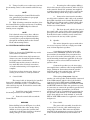
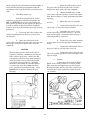
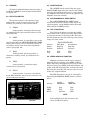
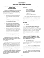
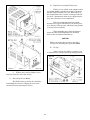
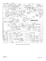
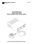
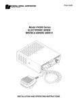
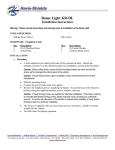
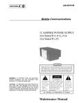
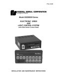
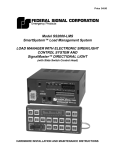
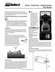
PRICE $4.00
MODEL PA500F
ELECTRONIC SIREN
SERIES B
INSTALLATION AND SERVICE INSTRUCTIONS
SECTION I
GENERAL DESCRIPTION
Figure 1-1. Model PA500F Electronic Siren.
The Model PA500F is designed to drive one or
two 58 or 100 watt speakers. Using two 100-watt
speakers will provide maximum traffic clearing
power.
The Federal Model PA500F is a precision built,
efficient and economical full-featured electronic siren
of advanced design. It provides wail, yelp and hi-lo
siren tones, as well as the Tap II feature, public
address (PA), radio rebroadcast and an air horn
sound.
The Tap II feature allows the driver to change
the siren sound from wail to yelp (or vice-versa) via
the vehicle’s horn ring or by activating the MANUAL
SIREN switch on the Control Head.
The siren may be installed in negative ground
vehicles with 12-volt electrical systems. It is protected against failure modes (including reversed
polarity) by a fuse that is replaceable without tools.
No components protrude from the bottom of the siren
to interfere with mounting arrangements.
Other special features of the Model PA500F
include:
The siren is made up of an Amplifier and a
Control Head. The Amplifier is suitable for mounting
in a dry, adequately ventilated location, while the
Control Head is designed for flush mounting in the
vehicle interior.
A noise-cancelling microphone is wired-in to
prevent loss or theft. It provides high quality voice
reproduction without feedback (squeal). The microphone push-to-talk switch overrides any siren signal
for instant PA use. PA and radio volume are preset at
the factory for maximum gain. Radio interconnect
wires are supplied as part of the control cable.
Additional cabling is not required.
1-1
•
High degree of reliability is achieved
through the use of integrated circuits and
silicon output transistors.
•
Control panel is illuminated with non-glare
lighting.
•
Newly designed printed circuit board
provides improved performance and durability under a wide range of environmental
conditions.
•
Use of screw-terminated terminal block for
easy installation of control cable at Control
Head.
SECTION II
SPECIFICATIONS
Input Voltage .
.
.
.
.
.
.
.
.
11 Vdc to 16 Vdc
Polarity
.
.
.
.
.
.
.
.
Negative ground electrical systems only
.
.
.
.
.
.
.
.
520mA (incl. panel lights)
Operating Current (Control Head & Ampl.)
.
13.3A ±1A (at 13.6V with 5.5-ohm load)
Frequency Range .
.
.
.
.
.
.
.
500 to 1500 Hz (nominal)
Cycle Rate .
.
.
.
.
.
.
.
Wail- 12 cycles/min.
Yelp- 180 cycles/min.
Hi-Lo- 60 cycles/min.
Voltage Output (approx.)
.
.
.
.
.
.
62V peak-to-peak
Audio Frequency Range
.
.
.
.
.
.
300 to 10KHz
Harmonic Audio Distortion.
(300-3000Hz)
.
.
.
.
.
10% max. all power levels from 1/2 to 50 watts
(frequency response ±3dB)
Operating Temperature Range .
.
.
.
.
-30°C to +65°C
Dimensions (HWD)
Control Head.
.
Amplifier Module
.
.
.
.
.
.
.
.
.
.
.
.
3" x 6" x 2"
3-1/4" x 4-1/2" x 7-3/8"
Net Weight
.
.
.
.
.
.
4-1/2 pounds
Shipping Weight (approx.) .
.
.
.
.
.
6 pounds
.
.
Standby Current
.
.
.
.
.
2-1
SECTION III
INSTALLATION
SAFETY MESSAGE TO INSTALLERS
OF
ELECTRONIC SIRENS
WARNING
The lives of people depend on your safe installation and servicing of Federal products. It is
important to read and follow all instructions
shipped with the products. In addition, listed
below are some other important safety instructions and precautions you should follow:
•
Sound output will be severely reduced if any
objects are in front of the speaker. If maximum sound output is required for your application, you should ensure that the front of
the speaker is clear of any obstructions.
•
Install the speaker(s) in a location which provides maximum signaling effectiveness and
minimizes the sound reaching the vehicle’s
occupants.
•
Installation of two speakers requires wiring
speakers in phase.
•
DO NOT install equipment or route wiring
or cord in the deployment path of an air bag.
•
Locate the control head so the vehicle, controls,
and microphone can be operated safely.
•
When drilling into a vehicle structure, be sure
that both sides of the surface are clear of anything that could be damaged.
•
If wiring is shorted to vehicle frame, high
current conductors can cause hazardous
sparks resulting in electrical fires or flying
molten metal.
Before Installation
Qualifications
•
To properly install an electronic siren: you
must have a good understanding of automotive electrical procedures and systems, along
with proficiency in the installation and service
of safety warning equipment.
Sound Hazards
•
•
Your hearing and the hearing of others, in or
close to your emergency vehicle, could be
damaged by loud sounds. This can occur from
short exposures to very loud sounds, or from
longer exposures to moderately loud sounds.
For hearing conservation guidance, refer to
federal, state, or local recommendations.
OSHA Standard 1910.95 offers guidance on
“Permissible Noise Exposure.”
All effective sirens and horns produce loud
sounds which may, in certain situations,
cause permanent hearing loss. You should
minimize your exposure times and wear suitable hearing protection.
After Installation
During Installation
•
•
•
DO NOT connect this system to the vehicle
battery until ALL other electrical connections
are made, mounting of all components is
complete, and you have verified that no
shorts exist.
Be sure the siren amplifier and speaker(s) in
your installation have compatible wattage
ratings.
In order for the electronic siren to function
properly, the ground connection must be
made to a solid chassis component and
not to an insulated point.
•
After installation, test the electronic siren,
speaker system, and light system to ensure
that it is operating properly.
•
Test all vehicle functions, including horn
operation and vehicle light systems, to ensure
proper operation.
•
After testing is complete, provide a copy of
these instructions to the instructional staff
and all operating personnel.
•
File these instructions in a safe place and
refer to them when maintaining and/or reinstalling the product.
Failure to follow all safety precautions and
instructions may result in property damage, serious
injury, or death to you or others.
3-1
3-1. UNPACKING.
3-3. CONTROL HEAD INSTALLATION.
After unpacking the Model PA500 F, examine it
for damage that may have occurred in transit. If the
equipment has been damaged, file a claim immediately with the carrier stating the extent of the
damage. Carefully check all envelopes, shipping
labels and tags before removing or destroying them.
WARNING
When installing equipment inside air bag
equipped vehicles, the installer MUST ensure
that the equipment is installed ONLY in areas
recommended by the vehicle manufacturer.
Failure to observe this warning will reduce the
effectiveness of the air bag, damage the air
bag, or potentially damage or dislodge the
equipment, causing serious injury or death to
you or others.
3-2. AMPLIFIER INSTALLATION.
A. Secure both mounting brackets to the
chassis with #10 thread-forming hex. head screws (2
for each bracket), as shown in figure 3-1.
CAUTION
The Control Head is designed to be flush
mounted in any relatively flat surface. To install,
proceed as follows:
The Amplifier is NOT waterproof. It must be
mounted in a location which is sheltered from
falling rain, snow, standing water, etc. Also,
it must be installed in an adequately ventilated area. Never install near heater ducts.
A. Select a location for the Control Head on
the mounting surface that does not impair the
drivers’ ability to safely drive the vehicle as he
operates the siren. The selected location should
afford good visibility and free accessibility to the
Control Head controls.
Do not mount the Amplifier under the vehicle’s
hood.
B. Select a suitable mounting location for the
Amplifier. Some possible mounting locations are: in
the equipment cabinet, under the front seat, or in the
trunk (under the rear deck, near the rear seat speakers, if vehicle is so equipped). Keep in mind that the
control cable is 10 feet long and the power cable is 8
feet long.
B. Place the mounting template, supplied in
the accessory kit, over the selected mounting location. Scribe a mark for each of the four mounting
holes. Also, scribe a cut mark along the heavy dark
line on the template.
C. Using the chassis mounting brackets as
templates, scribe four drill position marks at the
mounting location.
CAUTION
Take care not to damage wires or linkages
located behind the dashboard, while performing steps C. and D.
CAUTION
Before drilling holes in ANY part of a vehicle,
be sure that both sides of the mounting surface are clear of parts that could be damaged;
such as brake lines, fuel lines, electrical
wiring, or other vital parts.
C. Drill four 0.120 diameter (#31 drill) mounting holes at the marks scribed in step B.
D. The mounting hardware supplied in the
siren accessory kit provides the siren user with a
choice of mounting hardware; thread-forming screws
with lockwashers or 1/4-20 cap screws with
lockwashers and hex nuts. Consequently, the holes
drilled in the mounting surface must be appropriate
for the mounting screws selected. If the threadforming screws are to be used, drill 3/16" holes at the
drill position marks. Drill 9/32" holes at the position
marks if the 1/4-20 cap screws, lockwashers and nuts
will be used.
Secure the Amplifier to the mounting
surface, using the mounting hardware, including
lockwashers.
Figure 3-1. Mounting Bracket Installation.
3-2
D. Using a keyhole saw or sabre saw, saw into
the mounting surface at the cutmark scribed in step
B.
3. If routing the cable requires drilling a
hole in sheet metal or other material, drill a 5/8" hole
in the material. Install 5/8" grommet (not supplied)
or similar protective device in the hole, to protect the
cable from damage which sharp edges could cause.
NOTE
Before completing the Control Head installation, perform the procedures in paragraph
3-4, Electrical Installation.
4. Connect the wires from the 9-conductor cable and 3-conductor audio cable to the terminal
block (TB1) installed on the Control Head PC board.
The PC board is silk-screened to identify both cables
(audio and control), and wire colors are also identified for ease of installation.
E. With all wiring connections complete, place
the Control Head in position and secure to mounting
surface with four (4) #6B Phillips head threadforming screws (supplied).
5. The clear zip cord, which is also part of
the control cable, can be used to allow incoming radio
messages to be rebroadcast over the outside speaker.
To make this feature available, merely connect the
zip cord across the two-way radio’s speaker.
NOTE
If it is desired or necessary, three adhesive
backed gasket strips are included with the
accessory kit to prevent light from bleeding
through the mounting between the Control
Head and mounting surface.
B.
Speaker.
The unit is designed to operate with either
one or two low power (58-watt) or high power (100watt) 11-ohm impedance speakers.
3-4. ELECTRICAL INSTALLATION.
WARNING
A speaker is not included as part of the
electronic siren. FEDERAL speakers are weatherproof and may be installed in any convenient location; on the roof, fender, behind the grille, etc. Any
special mounting instructions applicable to the type
of speaker you have selected will be found in the
speaker carton.
Failure to observe this WARNING may result
in fire, burns or blindness.
If shorted to vehicle frame, high current conductors can cause hazardous sparks resulting
in electrical fires or molten metal.
DO NOT connect this system to vehicle battery until ALL other electrical connections
are made and mounting of all components is
complete.
Connect the speaker(s) to the siren using
user-supplied two conductor cable having 18AWG, or
larger, conductors. Connections from the speaker
should be made at the terminal strip , above the
control cable plug, as shown in figure 3-2.
Verify that no short circuits exist, before connecting to the Positive (+) battery terminal.
A.
Control Cable.
When using a low power (58-watt)
speaker, one of the speaker leads should be connected
to the COM terminal and the other lead should be
connected to the LO PWR terminal. High power
(100-watt) speakers should be connected to the COM
and HI PWR terminals. When two speakers are used,
it is necessary to connect the speakers in parallel and
in phase for optimum performance. On Federal
speakers, this can be accomplished by connecting the
two-speaker leads marked “1” to the COM terminal
on the siren and the two leads marked “2” to the HI
PWR or LOW PWR terminal (as applicable) as shown
in figure 3-2.
The control cable is designed to be installed
between the Amplifier and the Control Head. It
consists of a 9-conductor cable, a 3-conductor audio
cable and clear zip cord. To install the control cable,
proceed as follows:
1. Install the control cable connector to
the mating connector on the Amplifier.
2. Route the control cable toward the
Control Head.
C.
WARNING
Before drilling holes in ANY part of a vehicle,
be sure that both sides of the surface being
drilled are clear of parts that could be damaged; such as brake lines, fuel lines, electrical
wiring, linkages or other vital parts.
Power Cable.
The power cable assembly, located in the
accessory kit, is a 4-wire cable terminating in an
orange edge connector. This connector should be
installed on the mating 4-pin connector (J2) located
on the Control Head PC board, and should be ori
3-3
ented so that the wires protrude toward the middle of
the board. The following paragraphs describe the
installation of the leads at the other end of the power
cable.
1.
c.
Splice the white/yellow wire in
the power cable to the horn side of the cut wire.
Insulate the splice with a wire nut (supplied).
d. Obtain an SPST relay of sufficient contact current capacity to activate the vehicle
horn. Refer to figure 3-3 while performing the following steps.
Horn Ring (figure 3-3).
If the horn ring will not be used to
control siren operation, fold back and insulate the
YEL and WHT/YEL wires in the power cable and
disregard the procedure in this paragraph. However,
in order to utilize the Tap II and Press-and-Hold
features of the siren, the following procedure must be
performed.
e.
Mount the relay in a suitable
location.
f.
Connect the horn side of the wire
cut in step a. to the relay contact terminal.
g. Determine the “sense” of the
vehicle’s horn ring activation circuit, i.e. does the
horn circuit require a switched positive voltage or
switched ground for activation.
a. Locate the wire that connects the
vehicle horn ring switch to the horn or horn relay.
Cut this wire.
b. Splice the yellow wire in the
power cable to the horn ring side of the wire that was
cut in step a. Insulate the splice with a wire nut
(supplied).
h. Connect the relay wiper terminal
to the positive or negative potential determined in
step g.
i.
Connect the white/yellow wire in
the power cable to one end of the relay coil.
CAUTION
j.
Connect the other end of the relay
coil to the opposite potential of that connected to the
wiper in step h.
The horn ring transfer circuit of the siren is
capable of switching a maximum of 2-amperes.
Some vehicles do not have a horn relay and,
consequently, will draw more than 2-amperes
when the vehicle horn is activated. Consult
your vehicle service manual or a qualified
mechanic to determine the current required
to activate the horn. If it is less than 2-amperes, perform the procedure in step c. If it is
greater than 2-amperes, perform steps d.
through j.
2.
Ignition.
a. Connect the wire marked “IGNITION” to the vehicle ignition or accessory circuit.
This connection will supply power to the Control
Head panel lights and two-way radio control head
whenever the vehicle ignition key switch is in the
“on” position.
Figure 3-2. Speaker Connections.
Figure 3-3. Horn Ring Connections.
3-4
If necessary, drill a 5/8" hole in the
vehicle firewall. Install a user-supplied 5/8" grommet,
or similar device or material, to protect the wiring
and cabling against damage from rough edges.
b. Connect the wire marked
“GROUND” directly to the vehicle frame.
The Control Head can now be secured to the
vehicle dashboard.
D.
3. Route the fused power lead (spade
tongue lug end) from an area near the battery to the
Amplifier. (Do not connect to battery at this time.) If
necessary, pass the lead through the 5/8" hole that
was drilled in step 2.
Amplifier Power Connections.
Locate the fused power lead and ground
lead in the accessory kit. Both leads are #14AWG.
1. Connect the spade tongue lug end of
the ground lead to the NEG terminal of the Amplifier. Connect the other end of this lead to the vehicle
chassis as close as practical to the Amplifier.
4. Connect the spade tongue lug on the
fused power lead to the POS terminal on the Amplifier.
5. Connect the ring terminal on the
remaining end of the power lead directly to the
positive terminal of the battery.
WARNING
Before drilling holes in ANY part of a vehicle,
be sure that both sides of the surface being
drilled are clear of parts that could be damaged; such as brake lines, fuel lines, electrical
wiring, linkages or other vital parts.
3-5. TESTING AFTER INSTALLATION.
After installation, test the electronic siren,
including horn operation, to ensure that it is operating properly.
2. If the Amplifier is installed in the
vehicle passenger compartment, it will be necessary
to drill a 5/8" hole in the vehicle firewall for the fused
power lead.
After testing is complete, provide a copy of this
manual to all operating personnel.
3-5
SECTION IV
OPERATION
SAFETY MESSAGE TO OPERATORS OF
FEDERAL SIGNAL ELECTRONIC SIRENS
AND LIGHT/SOUND SYSTEMS
WARNING
Signaling Limitations
The lives of people depend on your safe operation of Federal products. It is important to
read and follow all instructions shipped with
the products. In addition, listed below are
some other important safety instructions and
precautions you should follow:
•
Be aware that the use of your visual and audible signaling devices does not give you the
right to force your way through traffic. Your
emergency lights, siren, and actions are
REQUESTING the right-of-way.
•
Although your warning system is operating
properly, it may not alert everyone. People
may not hear, see, or heed your warning signal.
You must recognize this fact and continue
driving cautiously.
•
Situations may occur which obstruct your
warning signal when natural or man-made
objects are between your vehicle and others,
such as when you raise your hood or trunk
lid. If these situations occur, be especially
careful.
Qualifications
•
To properly use an electronic siren and
speaker(s): you must have a good understanding
of general vehicle operation, a high proficiency
in the use of safety warning equipment, and
thorough knowledge of state and federal
UNIFORM TRAFFIC CODES.
Sound Hazards
•
•
Your hearing and the hearing of others, in or
close to your emergency vehicle, could be damaged by loud sounds. This can occur from short
exposures to very loud sounds, or from longer
exposures to moderately loud sounds. For
hearing conservation guidance, refer to federal,
state, or local recommendations.
OSHA Standard 1910.95 offers guidance on
“Permissible Noise Exposure.”
Driving Limitations
All effective sirens and horns produce loud
sounds which may, in certain situations, cause
permanent hearing loss. You should minimize
your exposure times and wear suitable hearing
protection.
•
At the start of your shift, you should ensure
that the light/sound system is securely attached
to the vehicle and operating properly.
•
If the unique combination of emergency vehicle
equipment installed in your vehicle has
resulted in the siren controls being installed
in a position that does not allow you to operate
them by touch only, OPERATE CONTROLS
ONLY WHILE YOUR VEHICLE IS STOPPED.
•
If driving conditions require your full attention, you should avoid operating the siren
controls while the vehicle is in motion.
Sound Limitations
•
•
Maximum sound output will be severely reduced if any objects are in front of the speaker.
If your installation has obstructions in front
of the speaker, drive even more cautiously.
Continuing Education
•
Frequently inspect the speaker to ensure that
it is clear of any obstruction, such as mud or
snow, which will reduce maximum sound
output.
File these instructions in a safe place and
refer to them periodically. Give a copy of these
instructions to new recruits and trainees.
Failure to follow these safety precautions may
result in property damage, serious injury, or death to
you, to passengers, or to others.
4-1
4-3. ON/OFF SWITCH.
4-1. GENERAL.
The ON/OFF switch controls all power to the
Model PA500F. Depressing the switch to ON, illuminates the Control Head and activates a relay within
the Amplifier which allows power to be applied to the
Amplifier electronic circuitry.
All controls utilized during normal operation of
the Model PA500F are located on the Control Head
(see figure 4-1).
4-2. SELECTOR SWITCH.
4-4. AIR HORN/MANUAL SIREN SWITCH.
The Selector switch is a five-position rotary
switch used to select the mode of operation. The
following are positions on the Selector switch.
A.
The AIR HORN/MANUAL SIREN switch
activates the electronic air horn sound (up) in any
selected position, except RADIO and the peak-andhold sound in the STBY position
RADIO.
4-5. TAP II FUNCTIONS.
In this position, incoming radio messages
are amplified by the siren and rebroadcast over the
outside speaker.
B.
Tap II allows the driver to change the audible
siren sound via the vehicle’s horn ring. This feature
is especially effective for clearing traffic. The chart
below demonstrates how the horn ring can be used to
change the siren sound.
STBY.
In this position, it is possible to operate the
siren by activating the AIR HORN/MANUAL SIREN
switch. The siren can also be activated by means of
an auxiliary switch, such as the horn ring button
(refer to paragraph 4-6).
C.
TAP II FUNCTIONS
WAIL.
In this position, the siren produces a
continuous “wailing” sound , up and down in frequency.
D.
First Horn
Ring Tap
Produces
Second Horn
Ring Tap
Produces
Wail
Yelp
Yelp
Wail
Wail
Yelp
4-6. PRESS-AND-HOLD FUNCTION.
Additional alternate sounds can be activated
when the Selector switch is set to STBY or HI-LO.
While depressing and holding the horn ring and the
Selector switch set to STBY, peak-and-hold siren will
sound. In the HI-LO position the air horn will sound.
Releasing the horn ring will cause the siren to revert
back to the original function.
YELP.
In this position, a continuous rapid
“warbled” tone is generated.
E.
Selector
Switch
Position
HI-LO.
In this position, a two-tone sound will be
heard. This distinctive tone may be reserved for any
special indication situation.
The TAP II functions can also be activated by
depressing the MANUAL SIREN switch, as shown
below:
Selector
WAIL
YELP
HI-LO
1st Tap
(MANUAL)
Yelp
Wail
Air Horn
2nd Tap
(MANUAL)
Wail
Yelp
Hi-Lo
NOTE
Peak-and-hold siren and air horn are the
“Press and Hold” features.
Figure 4-1. Control Head Front View.
4-2
SECTION V
SERVICE AND MAINTENANCE
Communications and shipments should be
addressed to:
SAFETY MESSAGE TO PERSONNEL SERVICING
FEDERAL SIGNAL
ELECTRONIC SIRENS
Service Department
Federal Signal Corporation
2645 Federal Signal Drive
University Park, IL 60466
The lives of people depend on your safe servicing
of Federal products. It is important to follow all
instructions shipped with the products. In addition,
listed below are some other safety instructions and
precautions you should follow:
•
1-800-433-9132
(In Illinois) 1-708-534-3400
Read and understand all instructions in
this manual before servicing electronic
siren.
•
To properly service an electronic siren,
you must have a good understanding of
automotive electrical systems and emergency signalling procedures.
•
All effective sirens and horns produce
loud sounds which may cause, in certain
situations, permanent hearing loss. You
should take appropriate safety precautions such as wearing hearing protection.
If any unit is returned for adjustment or repair,
it can be accepted only if we are notified by letter or
phone in advance of its arrival. Such notice should
clearly indicate the service requested and give all
pertinent information regarding the nature of malfunction and, if possible, its cause.
5-2. SIREN.
•
DO NOT connect this system to the positive terminal of the battery until servicing
is complete, and you have verified that
there are no short circuits to ground.
•
In order for the electronic siren to function properly, the ground connection
must be made to a solid chassis component and not to an insulated point.
A.
General.
Any competent radio repairman or electronic technician should have little difficulty in
tracing and correcting a malfunction, should any
occur. For emergency replacement of any of the small
components, care must be used when soldering. Heat
easily impairs transistors, capacitors and circuit
boards. It is therefore advisable to use longnose
pliers or a similar heat sink on the lead being soldered.
If IC13 or C21 are replaced, it may be
necessary to adjust R57. With the Selector Switch set
to STBY, hold the AIR HORN/MANUAL SIREN
switch in the MANUAL SIREN position and adjust
R57 for 1400Hz at the siren output.
Failure to follow all safety precautions and
instructions may result in property damage, serious
injury, or death to you or others.
B.
Removal for Servicing.
5-1. GENERAL.
To remove the electronic assembly, located
inside the Amplifier chassis, for servicing; proceed as
follows (see figure 5-1):
Most of the component electronic parts used in
the Model PA500F are standard items that can be
obtained from any radio or electronics supply shop.
In order to reduce equipment down-time, Federal
recommends that the entire printed circuit board
(Part No.2001072) be replaced. The printed circuit
boards are relatively inexpensive allowing you to
keep an adequate supply in your repair shop.
1. Remove the four #10 thread-forming
hex head screws which secure the Amplifier chassis
to the mounting brackets (two screws on each
bracket). Lift the Amplifier away from the mounting
brackets.
The factory can and will service your equipment
or assist you with technical problems, should any
arise, that cannot be handled satisfactorily and
promptly locally.
2. Remove the four hex head screws on
the amplifier’s bottom which secure the cover to the
Amplifier chassis.
5-1
D.
Replacement of Output Transistors.
Failure of one or both of the output transistors (Q201, Q202) is usually the result of a defective
speaker (short circuited voice coil). Rebroadcast of
the unsquelched radio or music for long periods will
also have a detrimental effect on the output transistors, and is therefore not recommended.
Federal recommends that both output
transistors be replaced should only one device prove
to be defective. This practice will insure long periods
of service between failures.
When installing new output transistors,
insure that the Sil-Pad insulators are installed
between the heatsink and transistors.
CAUTION
Make certain that the speaker is not defective prior to installing the repaired PA500F.
E.
Testing.
After servicing is complete, perform a test
of all functions to ensure siren is operating properly.
Figure 5-1. Chassis Removal.
3. Remove the cover by sliding it away
from the connector end of the chassis.
C.
Removal of Circuit Board.
The PC Board is secured to the chassis by
four Phillips head screws. Unplug the four wafer
connectors before removing the screws.
Figure 5-2. Internal View.
5-2
5-3. REPLACEMENT PARTS LIST.
Reference
Designation
Q201, Q202
F1
DS1, 2, 3
Description
Part Number
Transistor, 2N5885, NPN, Power
Fuse, 20A, 3AG
Lamp, Panel
Insulator (Q201, Q202)
Main Circuit Board
(with parts installed)
Output Circuit Board
(with parts installed)
Control Head Circuit Board
(with parts installed)
Chassis
Cover
Amplifier Assembly
Control Assembly
Accessory Kit
Microphone
Output Transformer
5-3
125B432
148A127
149A117
235A123A-01
2001072A
200C907
200C908B
85361080A
85361081A
8536C1025B
85361030A
85361027A
258B577A-02
120C167A
Figure 5-3. Model PA500F Schematic Diagram.
255A207 I
REV. I 1295
Printed in U.S.A.