
1
4181M
ε
EUROTHERM
CHESSELL
Model 4181M
Chart recorder
User guide
Major functional parts
Hard keys (3)
Numeric entry
keypad
80-character display
Softkeys (5)
Door catch
(Lift and turn clockwise)
Door closed
Chart illumination lamp
(behind cover)
Platen release catches
(Upper paper tray behind)
Memory card slot (Power on-off switch behind)
Circuit board retainer
Configuration transfer
socket
LA248163
Print head
Lower paper tray
Door Open
Useful part numbers
PA244816
CH533151
LA246843
HA246958
HA247361
HA247733
HA248387
LA246779UK10
LA246779UK25
LA244180U100
LA249556
LA248163
GD248010Uxxx
Battery pack
Fuse
PC Configuration Tool
Communications Manual
Memory Card Instruction Manual
Graphics Unit Manual
Technical Manual
100 Shunt
250 Shunt
Input Attenuator
6-colour disposable print cartridge (Model 4181)
6-colour disposable print cartridge (Model 4180)
22 metre z-fold chart (xxx = N of chart divisions = 100 or 120)
Declaration of Conformity
Manufacturer's name:
Eurotherm Recorders Limited
Manufacturer's address
Dominion Way, Worthing, West Sussex,
BN14 8QL, United Kingdom.
Product type:
Industrial chart recorder
Models:
4180C (Status level F8 or higher)
4180M (Status level K8 or higher)
4181M (Status level A1 or higher)
Safety specification:
EN61010-1:1993/A2:1995
EMC emissions specification:
EN50081-2 (Group 1; Class A)
EMC immunity specification:
EN50082-2
Eurotherm Recorders Limited hereby declares that the above products conform to the safety
and EMC specifications listed. Eurotherm Recorders Limited further declares that the
above products comply with the EMC Directive 89 / 336 / EEC amended by 93 / 68 / EEC,
and also with the Low Voltage Directive 73/23/EEC
Signed:
Dated:
Signed for and on behalf of Eurotherm Recorders Limited
Peter De La Nouger de
(Technical Director)
IA249986U050 Issue 3 Jly 98
1998 Eurotherm Recorders Ltd.
Aall rights are strictly reserved. No part of this document may be reproduced, stored in a retrieval system or
transmitted in any form, or by any means, without the prior, written, permission of the copyright owner.
Eurotherm Recorders Ltd. reserves the right to alter the specification of its products from time to time
without prior notice. Although every effort has been made to ensure the accuracy of the information
contained herein, it is not warranted or represented by Eurotherm Recorders Ltd. to be a complete or up-todate description of the product.
180 MM MULTIPOINT RECORDER INSTALLATION AND OPERATION MANUAL
180 mm MULTIPOINT RECORDER
INSTALLATION AND OPERATION MANUAL
OVERALL CONTENTS LIST
Section
Page
SAFETY NOTES ........................................................................ i - 3
TERMINOLOGY ........................................................................ i - 4
1 INSTALLATION
1.1 INSTALLATION PROCEDURE ............................................... 1 - 3
1.2 UNPACKING THE RECORDER ............................................. 1 - 3
1.3 MECHANICAL INSTALLATION ............................................. 1 - 3
1.4 SUPPLY VOLTAGE CONNECTION ....................................... 1 - 3
1.5 SIGNAL WIRING ............................................................... 1 - 6
1.6 CONFIGURATION TRANSFER WIRING ................................ 1 - 9
1.7 CHART INSTALLATION /REPLACEMENT ............................... 1 - 10
1.8 PRINT CARTRIDGE REPLACEMENT ....................................... 1 - 11
SECTION 2 BASIC OPERATION
2.1 FIRST SWITCH ON ............................................................ 2 - 2
2.2 OPERATOR INTERFACE ........................................................ 2 - 34
2.3 CONFIGURATION EXAMPLE ............................................... 2 - 7
2.4 COPY CONFIGURATION ................................................... 2 - 16
SECTION 3 OPERATOR MENUS
3.1 INTRODUCTION ................................................................ 3 - 5
3.2 TOP LEVEL OPERATOR MENU PAGE 1 ................................. 3 - 6
3.3 TOP LEVEL OPERATOR MENU PAGE 2 ................................. 3 - 14
3.4 TOP LEVEL OPERATOR MENU PAGE 3 ................................. 3 - 18
3.5 TOP LEVEL OPERATOR MENU PAGE 4 ................................. 3 - 20
4 CONFIGURATION
4.1 INTRODUCTION ................................................................ 4 - 5
4.2 INSTRUMENT CONFIGURATION ........................................ 4 - 8
4.3 CHART CONFIGURATION .................................................. 4 - 12
4.4 CHANNEL / ALARM CONFIGURATION ............................... 4 - 14
4.5 GROUP CONFIGURATION ................................................. 4 - 28
4.6 INTERNAL EVENT CONFIGURATION ................................... 4 - 29
4.7 LOG CONFIGURATION ..................................................... 4 - 31
4.8 COPY CONFIGURATION ................................................... 4 - 32
4.9 OPTIONS CONFIGURATION .............................................. 4 - 33
(Continued)
YEAR
2000
COMPLIANT
HA247645
Issue 10 Nov 98
YEAR 2000 COMPLIANCE
All software versions of non-graphics products, and software versions 2.7 onwards of products
with graphics displays, comply with the requirements of the British Standards Institute
document 'Disc PD2000-1. A Definition of Year 2000 Conformity Reqirements', when the
product is used as specified in this manual.
Section i
Page i - 1
180MM MULTIPOINT RECORDER INSTALLATION AND OPERATION MANUAL
List of Contents (Cont.)
Section
Page
4.10 TRANSFER CONFIGURATION ........................................... 4 - 33
4.11 DIAGNOSTICS ................................................................. 4 - 34
4.12 AUTOCONFIGURATION .................................................. 4 - 38
4.13 OPERATOR ACCESS CONFIGURATION ............................. 4 - 38
4.14 ADJUST ........................................................................... 4 - 41
4.15 PRINT CONFIGURATION .................................................. 4 - 46
5 OPTIONS
5.1 INSTALLING NEW OPTIONS .............................................. 5 - 3
5.2 TOTALISER / COUNTER / TIMER (TCT) OPTION .................... 5 - 4
5.3 MATHS PACK .................................................................... 5 - 10
6 SERVICE
6.1 CHART ILLUMINATION TUBE REPLACEMENT ........................ 6 - 2
6.2 BATTERY REPLACEMENT ..................................................... 6 - 2
7 REFERENCE
7.1 RECORDER MESSAGES ...................................................... 7 - 2
7.2 COSHH DATA .................................................................... 7 - 4
7.3 LIST OF EFFECTIVE PAGES .................................................. 7 - 8
7.4 GLOSSARY OF TERMS ........................................................ 7 - 9
ANNEX A RECORDER SPECIFICATION
A1 GENERAL SPECIFICATION ................................................... A - 2
A2 UNIVERSAL 8-CHANNEL INPUT BOARD SPECIFICATION ....... A - 4
A3 16 CHANNEL DC INPUT BOARD SPECIFICATION ................. A - 6
A4 RELAY OUTPUT BOARD SPECIFICATION ............................... A - 7
A5 ANALOGUE OUTPUT BOARD SPECIFICATION ...................... A - 7
ANNEX B PREVIOUS RECORDER MODELS
B1 INTRODUCTION ................................................................. B - 3
B2 CHART INSTALLATION/REPLACEMENT ................................. B - 4
B3 PRINT CARTRIDGE REPLACEMENT ........................................ B - 6
INDEX
Full sectional contents lists appear at the beginning of each chapter
Section i
Page i - 2
HA247645
Issue 10 Nov 98
180 MM MULTIPOINT RECORDER INSTALLATION AND OPERATION MANUAL
Safety Notes
1. Whenever it is likely that protection has been impaired, the unit shall be made inoperative and secured against
unintended operation. The nearest manufacturer’s service centre should be consulted for advice.
2. Any adjustment, maintenance and repair of the opened apparatus under voltage, should be avoided as far as possible and, if inevitable, shall be carried out only by a skilled person who is aware of the hazard involved.
3. The Mains (supply voltage) wiring must be terminated in such a way that, should it slip in the cable clamp, the
Earth wire would be the last wire to become disconnected.
WARNING!
Any interruption of the protective conductor inside or outside the apparatus, or disconnection of the
protective earth terminal is likely to make the apparatus dangerous under some fault conditions. Intentional interruption is prohibited.
4. Where conductive pollution (e.g. condensation, carbon dust) is likely, adequate air conditioning/filtering/sealing
etc. must be installed in the recorder enclosure.
5. This unit contains one or more batteries which must be treated and disposed of with care. In particular, batteries
must not be shorted or an explosion can occur. Batteries should be disposed of in accordance with local regulations; they must not be discarded with normal refuse.
6. Signal and supply wiring should be kept separate from one another. Where this is impractical, shielded cables
should be used for the signal wiring. Where signal wiring is carrying (or could carry, under fault conditions) hazardous voltages *, double insulation should be used.
7. If the equipment is used in a manner not specified by the manufacturer, the protection provided by the equipment
might be impaired.
8. For both portable and panel mounting equipment, the protective earth terminal must remain connected (even when
the recorder is isolated from the mains supply) if any of the I/O circuits are connected to hazardous voltages*.
*
A full definition of ‘Hazardous’ Voltages appears under ‘Hazardous Live’ in BS EN61010. Briefly, under normal
operating conditions Hazardous voltage levels are defined as >30V RMS (42.4V peak) or >60V dc.
Symbols used on the recorder labelling
One or more of the symbols below may appear on the recorder labelling.
!
Refer to the Manual for instructions
Protective Earth
This recorder for ac supply only
This recorder for dc supply only.
Risk of electric shock
HA247645
Issue 10 Nov 98
Section i
Page i - 3
180MM MULTIPOINT RECORDER INSTALLATION AND OPERATION MANUAL
STATIC ELECTRICITY
High voltages (tens of kilovolts) can be generated on the human skin through a number of mechanisms, such as friction
between different materials (e.g. nylon and skin), and separation of similar materials (e.g. masking tape, nylon sheet).
The gate-oxide region of all metal oxide semiconductors (MOS) is extremely thin, and can be damaged by voltages as
low as 60 Volts. Modern MOS devices have built-in clamp diodes which reduce the incidence of obvious static damage
considerably. It is possible however, even with such clamping diodes, to produce a small rupture in the oxide layer.
This might not destroy the device immediately, but it m ay result in a gradual reduction in the performance of the device until, eventually, it fails.
For this reason, the following precautions should be taken when handling any recorder circuit board.
1. Personnel handling MOS devices, or circuit boards containing them, should wear anti-static materials such as cotton. Nylon clothing should be avoided.
2. All bench tops should be covered with conductive material (104 to 105 Ohms per square) maintained at the recorder
chassis potential.
3. Circuit boards removed from the recorder should be placed into a static-safe bag, initially at the recorder chassis
potential, for storage. Before re-fitting the board, the containing bag should again be returned to the recorder chassis potential.
4. Personnel handling MOS devices, or boards containing them, should wear a wrist strap connected (via a safety
resistor) to the bench top, or if appropriate, to a suitable grounding point on the rack.
5. Leads of MOS devices removed from circuit should be shorted together using conductive foam or similar.
6. MOS devices should not be extracted from or inserted into circuit whilst the circuit board has power applied.
TERMINOLOGY
Anti-static
This term means that the material in question does not of itself generate static electricity. Such materials do not afford
protection against external electric fields.
Static safe
This means that the material in question a) does not generate static electricity, and b) any device enclosed in such material is safe from the effects of external electric fields.
Section i
Page i - 4
HA247645
Issue 10 Nov 98
180 mm MULTIPOINT RECORDER INSTALLATION AND OPERATION MANUAL
SECTION 1: INSTALLATION
LIST OF CONTENTS
Section
1.1
1.2
1.3
1.4
page
INSTALLATION PROCEDURE ...............................................
UNPACKING THE RECORDER .............................................
MECHANICAL INSTALLATION .............................................
SUPPLY VOLTAGE CONNECTION .......................................
1
1
1
1
-
3
3
3
3
1.4.1 Supply voltage selection ......................................................... 1 - 3
1.4.2 Supply voltage wiring ............................................................ 1 - 5
1.4.3 Supply voltage fuse ................................................................ 1 - 5
1.5 SIGNAL WIRING ............................................................... 1 - 6
1.5.1 The analogue output board as a transmitter power supply .......... 1 - 6
ANALOGUE OUTPUT CHANNEL ....................................... 1 - 6
ANALOGUE INPUT CHANNEL .......................................... 1 - 6
1.6 CONFIGURATION TRANSFER WIRING ................................ 1 - 9
1.7 CHART INSTALLATION / REPLACEMENT .............................. 1 - 10
1.7.1 Old chart removal ................................................................. 1 - 10
1.7.2 Fitting a new chart ................................................................. 1 - 10
1.8 PRINT CARTRIDGE REPLACEMENT ....................................... 1 - 11
Notes:
1.
If the recorder is to be left for an extended period without power applied, it is recommended that the
print cartridge be removed from the recorder (section 1.8) and stored separately in a sealed container.
2
The instrument can weigh up to 20 kg. It is therefore recommended that a risk assessment be carried
out before it is handled.
Note:
Sections 1.7 and 1.8 describe chart and print cartridge replacement procedures for current recorders. For
previous versions of the recorder, see Annex B towards the end of this manual. The two versions of the
recorder are distinguished most easily by examining the print cartridge.
As can be seen from the front views shown in the figure below, the two types are visually quite different;
they are not physically interchangeable.
LA 248 163
New version
HA247645
Issue 10 Nov 98
Original version
Section 1
Page 1 - 1
180 mm MULTIPOINT RECORDER INSTALLATION AND OPERATION MANUAL
This page is deliberately left blank
Section 1
Page 1 - 2
HA247645
Issue 10 Nov 98
180 mm MULTIPOINT RECORDER INSTALLATION AND OPERATION MANUAL
SECTION 1 INSTALLATION
1.1 INSTALLATION PROCEDURE
The installation procedure is as follows:
1. Unpack the recorder (section 1.2)
2. If the recorder is to be panel mounted, fit the recorder into the panel (section 1.3)
3. Connect supply and signal wiring (sections 1.4 and 1.5)
4. Fit chart and printhead (sections 1.7 and 1.8)
5. Switch on. Configure the recorder.
1.2 UNPACKING THE RECORDER
The recorder is shipped in a special pack, designed to ensure adequate protection during transit. Should the outer box
show signs of abnormal wear or damage, it should be opened immediately and the recorder examined. If there is evidence of damage, the instrument must not be operated and the local representative contacted for instructions. After the
recorder has been removed from its packing, the packing should be examined to ensure that all accessories and documentation have been removed.
1.3 MECHANICAL INSTALLATION
As shown in figure 1.3 below, the recorder is intended for installation in a 281 mm x 281 mm cutout, in a panel which
is either vertical or sloping up to 30 degrees. Particular attention should be paid to the recommended minimum distances between adjacent recorders. These distances are advised in order to retain ease of access, to allow full door
opening and for panel strength considerations.
The instrument is inserted through the panel cutout, from the front. With the weight of the recorder supported, the
panel clamps are clipped into the holes located, one each side of the recorder. The jacking screws should now be
tightened until the springs of the panel jacks are compressed to approximately half of their free length.
Once the recorder is securely mounted, the door should be opened (by lifting and then turning the latch clockwise) and
the internal packing removed and stored with the external packing, against future transport requirements.
1.4 SUPPLY VOLTAGE CONNECTION
All connections are made at the rear of the recorder. Supply voltage wiring, supply voltage selection and fuse replacement can all be carried out without the removal of the terminal cover.
1.4.1 Supply voltage selection
As shown in figure 1.4.1 (page 1-5), the supply voltage setting switch is located to the right of the fuse drawer associated with the IEC plug. The switch is operated upwards (230V indicated) to select 180 to 264 V, or downwards
(115V indicated) to select 90 to 132V.
Down for 90
to 130 V
Up for 180
to 264V
HA247645
Issue 10 Nov 98
230
OR
115
Section 1
Page 1 - 3
180 mm MULTIPOINT RECORDER INSTALLATION AND OPERATION MANUAL
Front
View
46 mm.
(1.8 in)
304 mm. (12 in.)
271 mm (10.67 in)
View on right
hand side
278 mm (10.95 in)
288 mm (11.4 in)
288 mm (11.4 in)
Maximum panel thickness
42 mm (1.66 in)
Top view
278 mm (10.95 in)
Terminal cover
Overall case dimensions
45mm (1.8in) (min)
281 x 281 mm
( 0.00 + 0.05)
11.07 x 11.07 in.
(-0.00 + 0.05 in)
Vertical
35mm (1.4in) (min)
30 30
Panel cutout
Maximum installed angles
Figure 1.3 Mechanical installation
Note: If this is a graphics recorder consult the Graphics Unit Manual for special installation instructions.
Section 1
Page 1 - 4
HA247645
Issue 10 Nov 98
180 mm MULTIPOINT RECORDER INSTALLATION AND OPERATION MANUAL
1.4.2 Supply voltage wiring
Before connecting the supply to the recorder, check that the recorder voltage select switch has been set to the correct
voltage range, as described above.
Before proceeding further, please read the warnings on page i - 3.
The line supply is terminated using an IEC socket which is connected into the mating plug at the rear of the recorder
power supply (figure 1.4.1). Recommended minimum wire size is 16/0.2 (0.5 mm2)
1.4.3 Supply voltage fuse
The supply fuse is located in a pull-out drawer integral with the IEC plug. The fuse specifications (3.15 Amp type F)
are the same for both supply voltage ranges, and are as follows:Rating
Size
Speed
Material
3.15 Amps
20 mm
Fast blow
Ceramic
It should be ensured that only fuses with the required rated current and of the specified type are used for replacement.
The use of makeshift fuses, and the short-circuiting of fuse holders are prohibited, and will invalidate the manufacturer’s warranty.
Ch 1
Slot 1
Slot 2
Slot 3
Line power
connector
Earth Stud
230
Fuse
Battery
drawer
pack cover
Supply
voltage
selector
Serial
comms.
module
(optional)
Figure 1.4.1 Recorder rear view with terminal cover removed
HA247645
Issue 10 Nov 98
Section 1
Page 1 - 5
180 mm MULTIPOINT RECORDER INSTALLATION AND OPERATION MANUAL
1.5 SIGNAL WIRING
All signal wiring terminations are located behind the terminal cover (figure 1.3). This acts not only as protection, but
also as a thermal ‘container’ to reduce temperature fluctuations as much as possible for the thermocouple cold junction
terminations. To remove the rear cover, release the screw securing it to the rear of the recorder. Slot 1 is the topmost
slot, and channel 1 is the right-most channel.
Figure 1.5 shows signal wiring for the various inputs supported by the recorder.
Note: Recommended maximum wire size is 2.5 mm2
1.5.1 The analogue output board as a transmitter power supply
Each analogue output channel can be wired to provide 24V at up to 25mA as shown in figure 1.5.1 below. Typical
configuration pages are as follows:
Analogue output channel
The analogue output channel should be set up as follows (see section 4 for details):
O/P Type mA
4.00 to 24.00
Source
Constant
24.000
Enabled
Value Format XXX.XX
On error
Drive hi
To find the channel number, the 'CARDS' section of the 'INSTRUMENT' configuration should be accessed, to find the
address of the analogue output board. Each address is associated with 8 channels, so an address of two, for example,
means that the first analogue output channel is 9.
Analogue input channel
I/P Type mA
4.00 to
Shunt 100.00 ohms
20.00
Lin Func. Linear
Unscaled
Value format XXX.XX
Damping None
(Continued)
Section 1
Page 1 - 6
HA247645
Issue 10 Nov 98
180mm MULTIPOINT RECORDER INSTALLATION AND OPERATION MANUAL
8-Channel input board signal wiring
Chan
6
Chan
7
Chan
4
Chan
5
18 17 16 15 14 1312 11 10 9 8 7 6 5 4 3 2 1
CV I
Polarising key
Polarising key
Polarising key
Chan
8
CV I
CV I
CV I
Chan
2
Chan
3
C
V
V
Chan
1
Ch Ch Ch Ch
16 15 14 13
2-Wire RTD inputs
V
I
3 - Wire RTD inputs
C
V
I
Ch3
Ch Ch
2
1
V- V+ V- V+ V- V+ V- V+
CV I
CV I
V- V+ V- V+ V- V+ V- V+
V- V+ V- V+ V- V+ V- V+
DC Volts 10V
I
C
V
DC mA
DC volts (<10V);
DC mV; Thermocouples
I
Attenuator
assembly
Current inputs should
not be connected here
+
-50 to +100V
Potentiometric inputs
C
V
V+
V-
Contact inputs
V+
V-
V+
V+
nc
+
Signal input
Contact inputs
I
C
V
Attenuator
assembly
+
Signal input
+
-1 to +50V
c
no
Microswitch, Relay
contact etc.
no
In order to prevent incorrect board types being fitted, a polarising key can be inserted between
contacts 5 and 6 of each connector
Microswitch,
Relay contact
etc.
Potentiometer
Shunt
assembly
I
nc
Resistance
thermometer
DC Volts 10V
Voltage inputs should
not be connected here
c
Resistance
thermometer
Ch
4
V- V+ V- V+ V- V+ V- V+
CV I
+
Signal input
connected here
Ch Ch Ch Ch
8
7
6
5
CV I
VShunt
assembly
Ch Ch
10 9
18 17 16 15 14 13 12 11 10 9 8 7 6 5 4 3 2 1
I
+
Signal input Voltage/thermocouple
inputs should not be
Polarising key
18 17 16 15 14 13 12 11 10 9 8 7 6 5 4 3 2 1
V-
C
Ch
12
Ch11
18 17 16 15 14 13 12 11 10 9 8 7 6 5 4 3 2 1
DC mA
C
16-Channel input board signal wiring
Relay output board signal wiring
In order to prevent incorrect board types being fitted, a polarising key can be inserted
between contacts 15 and 16 of each connector
INTERNAL (BOARD) WIRING
Contacts shown in alarm (de-energised) state
4/8-channel analogue output board signal wiring
Polarising key
Ch 8
Ch
7
Polarising key
Ch 4
Ch 5
Ch 6
18 17 16 15 14 13 12 11 10 9 8 7 6 5 4 3 2 1
C Vo Io
C Vo Io
C Vo Io
C Vo Io
Voltage output
C
This connector
fitted but not
wired with fourchannel option
Vo
+
Io
Normally closed
ONLY ONE CHANNEL SHOWN FOR CLARITY
Ch
3
Ch 2
Ch 1
18 17 16 15 14 13 12 11 10 9 8 7 6 5 4 3 2 1
C Vo Io
C Vo Io
C Vo Io
Common
C Vo Io
Normally open
Relay coil operated by JOB
as set up in channel / event /
totaliser etc. configuration
Current output
C
Vo
Io
+
In order to prevent incorrect board types being fitted, a polarising key can be inserted between
contacts 13 and 14 of each connector
Polarising key
Polarising key
18 17 16 15 14 13 12 11 10 9 8 7 6 5 4 3 2 1
18 17 16 15 14 13 12 11 10 9 8 7 6 5 4 3 2 1
NO NC C
NO NC C
NO NC C
NO NC C
NO NC C
NO NC C
Chan 8
Chan 7
Chan 6
Chan 4
Chan 3
Chan 2
NO NC C
Chan5
NO NC C
Chan1
User connections
In order to prevent incorrect board types being fitted, a polarising key can be inserted between
contacts 4 and 5 of each connector
Figure 1.5 Sheet 1
Signal wiring - terminations
HA247645
Issue 10 Nov 98
Section 1
Page 1 - 7
180mm MULTIPOINT RECORDER INSTALLATION AND OPERATION MANUAL
Chan 16
Chan 9
Chan 8
Chan 1
Slot 1 : 16 channel
Chan 32
Chan 25
Chan 24
Chan 17
Slot 2 : 16 channel
Slot 3 : Empty
Chan 8
Chan 5
Chan 4
Chan 1
Slot 1 : 8 channel
Slot 2 : Empty
8 Channels
Slot 3 : Empty
Chan 8
Chan 5
Chan 4
Chan 1
Slot 1 : 8 channel
Chan 16
Chan 13
Chan 12
Chan 9
Slot 2 : 8 channel
Chan 32
Chan 25
Chan 24
Chan 17
Slot 3 : 16 channel
32 Channels
Chan 8
Chan 5
Chan 4
Chan 1
Slot 1 : 16 channel
Chan 8
Slot 2 : Empty
Chan 24
Slot 3 : Empty
Chan 4
Chan 1
Slot 1 : 8 channel
Chan 17
Chan 16
Chan 9
Slot 2 : 16 channel
Chan 32
Chan 29
Chan 28
Chan 25
Chan 7
Chan 1
Chan 5
Slot 3 : 8 channel
16 Channels
Chan 8
Chan 16
Chan 8
Chan 24
Chan 5
Chan 13
Chan 5
Chan 17
Chan 4
Chan 1
Slot 1 : 8 channel
Chan 16
Chan 8
Chan 12
Chan 9
Slot 2 : 8 channel
Chan 24
Chan 21
Chan 20
Chan 17
Slot 2 : 8 channel
Slot 3 : Empty
Chan 32
Chan 29
Chan 28
Chan 25
Slot 3 : 8 channel
Chan 5
Chan 4
Chan 1
Slot 1 : 8 channel
Slot 1 : 16 channel
Chan 4
Chan 1
Slot 1 : 8 channel
Chan 8
Chan 16
Chan 9
Slot 2 : 16 channel
Chan 24
Chan 17
Chan 16
Chan 9
Slot 2 : 16channel
Slot 3 : Empty
Chan 40
Chan 33
Chan 32
Chan 25
Slot 3 : 16 channel
Slot 1 : 16 channel
Chan 8
Chan 5
Chan 4
Chan 1
Slot 1 : 8 channel
Chan 16
Chan 13
Chan 12
Chan 9
Slot 2 : 8 channel
Slot 3 : Empty
Chan 24
Chan 21
Chan 20
Chan 17
Slot 3 : 8 channel
Chan 7
Chan 1
Slot 1 : 16 channel
Chan 16
Chan 8
Chan 7
Chan 1
Chan 24
Chan 21
Chan 20
Chan 17
Slot 2 : 8 channel
24 Channels
Chan 8
Chan 5
Chan 4
Chan 1
Slot 1 : 8 channel
Chan 16
Chan 8
Chan 16
Chan 13
Chan 12
Chan 9
Slot 2 : 8 channel
Chan 32
Chan 25
Chan 24
Chan 17
Slot 2 : 16 channel
Chan 24
Chan 21
Chan 20
Chan 17
Slot 3 : 8 channel
Chan 40
Chan 37
Chan 36
Chan 33
Slot 3 : 8 channel
Chan 16
Chan 8
Chan 7
Chan 1
Slot 1 : 16 channel
Chan 32
Chan 25
Chan 24
Chan 17
Slot 2 : 16 channel
Chan 48
Chan 41
Chan 40
Chan 33
Slot 3 : 16 channel
Figure 1.5 Sheet 2
Signal wiring - Channel locations
Figure 1.5 Sheet 2
Signal wiring - Channel locations
Section 1
Page 1 - 8
Section 1
Page 1 - 8
40 Channels
48 Channels
HA247645
Issue 10 Nov 98
180 mm MULTIPOINT RECORDER INSTALLATION AND OPERATION MANUAL
1.5.1 TRANSMITTER POWER SUPPLY (Cont.)
Analogue output
board
C
Vo
Analogue input
board
Io
C
V
I
Shunt
–
+
4 to 20 mA
current loop
Figure 1.5.1 Wiring of the analogue output as a Transmitter Power Supply
1.6 CONFIGURATION TRANSFER WIRING
As explained in section 4.10, the configuration of one recorder can be transferred to or from one or more other recorders using the 9-way D-type socket located inside the recorder, on the right-hand side, above the chart cassette. Figure
1.6a shows the cable specification for a connection between two recorders. No screen is necessary.
9-way Dtype Plug
2
ESI_LIS
2
3
ESI_TLK
3
5
5
Vss (0 V)
9
5V from recorder
5V from recorder
9-way Dtype Plug
9
Cable length: 2 metres (max.)
Wire type: 7/0.2 (0.22 mm2) min.
Figure 1.6a Cable specification for configuration transfer
Configuration transfer can also be carried out between the recorder and any host computer or configuration terminal
which is capable of accepting 5 V logic levels at its RS232 input, and which does not require hardware handshake. An
RS232 converter may be required with some computers to change the recorder's signals to 12 V.
Figure 1.6b shows how to wire the recorder link to host computer 9-way and 25-way D-types. It is up to the user to
determine whether a plug or socket is required at the host computer end of the link.
2
3
4
5
6
7
8
20
PC Tx
PC Rx
2
3
RTS
CTS
DSR
Ground
DCD
DTR
25-way D-type
connector
5
Recorder
connector
(9-way D-type)
1
2
3
4
5
6
7
8
DCD
PC Rx
PC Tx
2
3
DTR
Ground
5
DSR
RTS
CTS
9-way D-type
connector
Recorder
connector
(9-way D-type)
Figure 1.6b Configuration transfer port to host computer wiring
Alternatively, the communications option can be used. This allows not only configuration save and restore, but also
full configuration and monitoring functions.
A PC configuration tool is available from the manufacturer.
HA247645
Issue 10 Nov 98
Section 1
Page 1 - 9
180 mm MULTIPOINT RECORDER INSTALLATION AND OPERATION MANUAL
1.7 CHART INSTALLATION / REPLACEMENT
1 123.4 Deg C Ch1 Tag
2 LINE
MODE HOLD
NEXT
Note: See Annex B for previous recorder versions
Before fitting a chart, the chart drive must be switched
off, as follows:
a. Operate the ‘Home’ hard key.
b. Operate the ‘CHART’ softkey.
c. Operate the ON/OFF softkey, then the OFF or FAST
OFF softkey.
d. When ‘Printer is off line' appears, operate the PARK softkey and wait until the print cartridge parks somewhat to the right of centre.
e. Note the position of the ADVANCE softkey.
PREVIOUS
Operator select a category
DISPLAY CHART ALARM CHANNEL
Chart : select a category
ON/OFF SPEED LOG INT MODE
MORE>
SCALES
Printer is on line
OFF
FAST OFF
Printer is off line
ON
PARK
ADVANCE
1.7.1 Old chart removal
Open the door of the recorder by lifting the latch and rotating it
clockwise. If fitting a chart for the first time, or if the previous chart
has already been removed, go to section 1.7.2.
B
A
Pull the paper guide forwards, as shown (A), and disengage the remaining chart (B) from the drive sprockets. Pull the end of the chart
downwards clear of the platen.
Open the lower paper tray by rotating it forwards as shown (C) in the
figure, and remove the old chart.
C
Figure 1.7.1 Chart removal
Remove any residual paper dust from the paper tray.
1.7.2 Fitting a new chart
Release the platen by pushing upwards on one or both latches (D). Swing
the platen forwards to reveal the upper paper tray. Remove any residual
paper dust.
Check that the printhead guide bars are clean and shiny and
that the drive belt and flexi cable for the printhead are in good
condition. If not, carry out remedial action as described in the
Service Manual.
Remove the new chart from its packing and fan (as shown in
figure 1.7.2a) several times to separate the leaves, and to remove loose paper dust. Ensure that the leaves are fully separated, or the paper transport will not operate correctly.
D
D
Orient the chart such that the red end-of-chart line is at the
bottom, and the circular chart holes are to the left (i.e. the elongated slots are to the right). Load the chart into the upper paper
tray and unfold the top three or four leaves.
Section 1
Page 1 - 10
Figure 1.7.2a Loading the new chart
HA247645
Issue 10 Nov 98
180 mm MULTIPOINT RECORDER INSTALLATION AND OPERATION MANUAL
1.7.2 FITTING A NEW CHART (Cont.)
As shown in figure 1.7.2b, feed the top few leaves between the
paper guide and the platen, then push the platen closed ENSURING THAT IT LATCHES CORRECTLY INTO PLACE.
With the paper guide pulled forwards, feed the end of the chart
through the gap between the platen and the paper guide, and lay
the first two or three leaves in the bottom (take-up) paper tray..
Close the paper guide, ensuring that both sets of chart holes
locate correctly on the drive sprockets, and that the horizontal
grid lines are parallel with the chart guide.
If the chart is loaded correctly, the circular holes will be on the
left, and the printed grid will be uppermost, with no red line
showing.
Figure 1.7.2b Chart loading
Ensure that the paper lies naturally (i.e. the fold direction is the same as when packed by the chart manufacturer),
then use the ADVANCE softkey to feed more chart through, to ensure it is moving smoothly.
FAILURE TO ENSURE THAT THE CHART FOLDS NATURALLY WILL RESULT IN THE EVENTUAL
MALFUNCTIONING OF THE CHART FEED.
1.8 PRINT CARTRIDGE REPLACEMENT
Caution
Before attempting to change the print cartridge it is essential to ensure that the printhead/cartridge is
parked, as described in section 1.7, above, otherwise it will not be possible to change the cartridge
without risk of damage.
Note:
1 To ensure maximum printhead life, it is recommended that the print cartridge be removed and stored
separately, in a sealed container, if the recorder is to be left unpowered for an extended period.
2 See Annex B for previous recorder versions.
3. In order to avoid getting ink marks on the hands, it is recommended that a pair of disposable gloves
be used when handling the print cartridge.
Switch the printer off-line and park the printhead as described in section 1.7 above.
Open the platen by pushing upwards on one or both latches.
Carefully pull the printhead downwards as shown in figure
1.8, to remove it.
Unpack the new print cartridge and push it upwards into the
carriage, ensuring that it is pushed fully home, close the
platen and return the recorder to service.
Figure 1.8 Print cartridge replacement
HA247645
Issue 10 Nov 98
Section 1
Page 1 - 11
180 mm MULTIPOINT RECORDER INSTALLATION AND OPERATION MANUAL
This page is deliberately left blank
Section 1
Page 1 - 12
HA247645
Issue 10 Nov 98
180 MM MULTIPOINT RECORDER INSTALLATION AND OPERATION MANUAL
SECTION 2: BASIC OPERATION
LIST OF CONTENTS
Section
Page
2.1 FIRST SWITCH ON ............................................................ 2 - 2
2.2 OPERATOR INTERFACE ........................................................ 2 - 3
2.2.1 Display control hardkeys ........................................................ 2
HOME KEY ..................................................................... 2
ENTER KEY ...................................................................... 2
CANCEL KEY .................................................................. 2
2.2.2 Status indicators .................................................................... 2
2.2.3 Text editing ........................................................................... 2
NORMAL CHARACTER SET ............................................... 2
ALTERNATIVE CHARACTER SET ......................................... 2
-
3
3
3
3
4
4
4
4
2.3 CONFIGURATION EXAMPLE ............................................... 2 - 7
2.3.1
2.3.2
2.3.3
2.3.4
Required channel inputs / outputs ............................................ 2
Accessing configuration ......................................................... 2
Chart speed .......................................................................... 2
Channel range ...................................................................... 2
INPUT TYPE, RANGE ETC. ................................................ 2
LINEARISATION TYPE AND SCALING ................................ 2
DISPLAY FORMAT, DAMPING AND BREAK .........................
RESPONSE ..... 2
2.3.5 Channel alarms ..................................................................... 2
ALARM TYPE AND SETPOINT ............................................ 2
ALARM ACTIONS ............................................................ 2
2.3.6 Channel zone ....................................................................... 2
SETTING THE CHART AREA FOR TRACING ........................ 2
CHART SCALE ................................................................. 2
2.3.7 Channel trace ....................................................................... 2
TRACE ON/OFF; TRACE COLOUR ................................... 2
2.3.8 Channel identification ............................................................ 2
SETTING TRACE IDENTIFIERS ............................................ 2
2.3.9 Group configuration .............................................................. 2
SELECTING THE GROUP .................................................. 2
DEFINING THE GROUP CONTENTS .................................. 2
GROUP FORMAT ............................................................. 2
2.3.10 Selecting the group for display .............................................. 2
2.3.11 Printing the configuration on the chart .................................... 2
-
7
7
8
8
8
9
-
9
10
10
10
11
11
11
12
12
12
12
13
13
13
13
14
14
2.4 COPY CONFIGURATION ................................................... 2 - 16
2.4.1 Copy range and zone ............................................................ 2 - 16
2.4.2 Trace colour .......................................................................... 2 - 17
2.4.3 Trace Identifiers ..................................................................... 2 - 17
HA247645
Issue 9 Jly 98
Section 2
Page 2 - 1
180 MM MULTIPOINT RECORDER INSTALLATION AND OPERATION MANUAL
2: BASIC OPERATION
This section is designed to help you as a new user to configure a channel to a set of basic parameters so you can start
recording your own traces with the minimum of effort.
For full information about Operator and Configuration displays see sections 3 and 4/5 respectively.
Figure 2.3 is a type of map to help show you round the top level menus of the recorder. The diagram shows all available options. If an option isn’t fitted then its softkey doesn’t appear, so your displays might be slightly different from
those shown.
2.1 FIRST SWITCH ON
To apply power to the recorder, open the recorder door, release the
platen by pushing upward on the catches. With the platen open, the
power on-off switch can be located as shown in figure 2.1.
When the recorder is switched on, an initialisation message appears
briefly at the display, and a ‘Power on’ message is printed on the
chart. The message includes the current time and date, the print
mode (trace priority) and chart speed (120mm / hr).
After initialisation is complete, the display goes into ‘background
mode’ i.e. it displays a single channel’s number, status or value and
‘tag’ on the top line, and will have a series of ‘softkey’ legends on
the lower line.
01
2 LINE
OFF
MODE
1
HOLD
NEXT
Figure 2.1 On-off switch location
PREVIOUS
⇐ Softkey legends
The softkeys (2 LINE, MODE etc.) are fully described in section 3.
The first channel to be displayed is the first channel fitted (normally 1).
After approximately 3 seconds, the display changes to show channel 2 and so on until all the measuring channels have
appeared. After all the measuring channels have been ‘scrolled through’ in this way, any option values (maths channels, totalisers/counters) are displayed in turn, before channel 1 is returned to.
As delivered, all channels are set to OFF. In order to carry out measurements and start tracing, you need to tell the
recorder what input types are wired to each channel, what ranges and scales to use, alarm setpoints, alarm types and so
on.
To do this, you need to access the configuration menus, but before you do, here is some basic information you need to
do the job.:
Section 2
Page 2 - 2
HA247645
Issue 9 Jly 98
180 MM MULTIPOINT RECORDER INSTALLATION AND OPERATION MANUAL
2.2 OPERATOR INTERFACE
The ‘Operator interface’ is the name given to the display and its associated hardkeys (including numeric keys) and
softkeys.
05 542.95 Furn01A
2 LINE
MODE
-->
Display
control
hardkeys
(Clear)
(Page scroll)
(Move cursor)
TYPE
(Next item)
(Previous item)
7
8
9
4
5
6
1
2
3
0
+
Numeric
keypad
Softkeys (with configuration functions)
Figure 2.2 Display / keyboard
2.2.1 Display control hardkeys
These three keys, located to the left of the display, help you to access and edit items with minimum effort.
HOME KEY
The 'HOME' key is used one or more times to return you to the top level menus as follows:.
a. If the display is in background mode, a single operation of this key will call the top level operator menu.
b. If you are in the operator menus operation of the 'HOME' key will return you to the top level operator menu.
c. During configuration, a single operation of the key will return to the top level configuration menu, a second operation will return you to the operator top level menu.
ENTER KEY
The 'Enter' key is used to confirm any changes to operation or configuration made since the last time it was operated. If
no such changes have been made, the key moves you up one menu level
CANCEL KEY
The cancel key is used to 'undo' any changes made since the Enter key was last operated. If no such changes have been
made, the key moves you up one menu level.
HA247645
Issue 9 Jly 98
Section 2
Page 2 - 3
180 MM MULTIPOINT RECORDER INSTALLATION AND OPERATION MANUAL
2.2.2 Status indicators
During normal operation of the recorder (i.e. not in configuration), characters 39 and 40 of the top line of the display
are used to indicate recorder / input status as follows.
P
I
Channel alarm. This bell symbol flashes whenever an unacknowledged active alarm is present. The bell is steadily
illuminated if an acknowledged alarm is present but again flashes if a further unacknowledged alarm becomes active.
See section 3.2.3 for how to acknowledge alarms.
Printer off indicator. This appears if the printer drive has been switched off.
System error indicator The System error indicator appears if any of the items listed below is true. Any current system
errors can be viewed via the Operator menu (Section 3) or instrument configuration pages (section 4.2)
1.
2.
3.
4.
5.
6.
7.
There is a fault with remote CJ temperature.
The battery is exhausted or missing.
There is a failure in the real-time clock or the time/date have not been set.
There is a fault in the writing system.
There is a fault in an input or derived channel.
Battery-backed RAM failure or EEPROM failure.
Memory card battery low or exhausted.
2.2.3 Text editing
+
Text entry is by means of the cursor and up and down scroll keys together with the
–
key.
The cursor (right arrow) key is used to locate the cursor beneath the character to be edited and the scroll keys are then
used to scroll through either of the character sets depicted (approximately) below.
Notes:
1.
The two sets can be switched between using the key associated with the numeric keyboard.
2.
The clear key
can be used to clear the text string from the cursor position to the end inclusive.
3.
Should an error be made, the cancel key can be used to ‘undo’ all changes so far made to the text
string.
4.
Under certain circumstances, it is possible to have the current time, date etc. included in a message
to be printed in the chart. See the ‘Embedded Sequences’ description in section 3.3.3.
Normal character set
A to Z, a to z, Ä ä à ç ê è é Ö ö ô Ü ü ù β Σ µ Ω δ (space) # $ % & ( ) * + ,
- . / : ; < = > _ £˚ 0 to 9, (Space)
Alternative character set
!❝ ❜ [ \ ] ^❛{ | } ~ Çâ å ë ï ì Å É æ Æ ò û ÿ ¢ ¥ á í ó ú ñ Ñ a o ¿ ¡ « » α Γ πσ τ φ θ ∞∈
∩ ≡ ± ≥ ≤ ÷ ≈ •.√ η •
2 3
Section 2
Page 2 - 4
HA247645
Issue 9 Jly 98
180mm MULTIPOINT RECORDER INSTALLATION AND OPERATION MANUAL
For full details of operator and configuration menus, see sections 3 and 4 respectively
'Background display'
01
OFF
2 LINE
1
MODE
HOLD
NEXT
PREVIOUS
Operate 'Home' key to call 1st
Top level Operator page
Top level operator pages
Operator : Select a category
DISPLAY CHART
Operator : Select a category
ALARM CHANNEL MORE>
Chart : Select a category
ON/OFF SPEED LOG INT MODE
PROCESS
KEYS
TEXT
LOG
Operator : Select a category
MORE>
CLOCK JOB SRC SYS ERR CONFIG
Operator : Select a category
MORE>
M CARD
MORE>
Enter password **
SCALES
QUIT
ENTER
The password is set to 10 by the manufacturer.
You can change it as a part of the Instrument configuration
(INSTRM softkey - see section 4.2)
Printer is on line
OFF FAST OFF
Printer is off line
ON
PARK ADVANCE
Chart must be off for configuration print.
Top level configuration pages
Configuration: select a category
INSTRM CHART CHANNEL GROUP
MORE>
Configuration : Select a category
EVENTS
LOGS
COPY
MATHS
MORE>
Configuration : Select a category
TOTAL'R COUNTER TIMER
COMMS
MORE>
Configuration : Select a category
TRANSFR
MCARD
DIAGS
AUTOCFIG MORE>
1 : Select a category
ALARM
ZONE
TRACE
IDENT
Chart : Select a category
SPEED LOG INT MODE
FORMAT TRACES
PRINT
MORE>
ALL
CHANNEL TRACE
ALARM
MORE>
ALARM
Configuration for group : Everything
CONTENT FORMAT TITLE
NEXT PREVIOUS
Channel
RANGE
ACCESS ADJUST
Configuration print: select a category
Configuration copy : Select a category
CHANNEL MATHS
Configuration : Select a category
COPY CHANNEL/
ALARM CONFIGURATION
Configuration print in progress
STOP
This diagram shows all options.
Your display pages may be different, since softkeys do not
appear for options which are not fitted.
PRINT CHANNEL CONFIGURATION
BASIC
CONFIGURATION
Figure 2.3
Basic menu structure
HA247645
Issue 9 Jly 98
Section 2
Page 2 - 5
180mm MULTIPOINT RECORDER INSTALLATION AND OPERATION MANUAL
This page is deliberately left blank
Section 2
Page 2 - 6
HA247645
Issue 9 Jly 98
180 MM MULTIPOINT RECORDER INSTALLATION AND OPERATION MANUAL
2.3 CONFIGURATION EXAMPLE
This section gives you a step-by-step guide showing you how to set up (configure) a single channel to accept a particular type of input signal and the range of temperatures to be measured; to set up the chart range, to enter a name for the
channel; and to select an alarm type and threshold. This is sufficient to get you going, but further sections are included to help you to copy your configuration to one or more further channels, how to set up a group for display, and
how to print your set-up on the chart.
2.3.1 Required channel inputs / outputs
Before you start to configure any channel you will need to know exactly what you want the recorder to do with the
input you are providing. It is recommended that, for each channel, you have a list of parameters which are to be set up
similar to the following imaginary example:
Channel Number
Temperature range
Display scale
Input type
Chart span
Chart scale
Input Break response
Trace
Descriptor
Tag
Alarm
5
0 to 900 ˚C
0.00 to 900.0 ˚C
Type K thermocouple, using the recorder’s internal cold junction for compensation.
400 to 800 ˚C
10 divisions
Upscale Drive.
Enabled; black; interpolation on.
Furnace No1 temp A
Furn01A
Tripped immediately if the temperature exceeds 780˚C, and remains tripped until acknowledged. Sounds internal buzzer whilst active.
The channel is to be displayed as a member of a group called ‘Furnace 1 temps’ which includes channels 5 to 8, and it
is to be traced with the recorder chart speed set to 60 mm/hr.
2.3.2 Accessing configuration
If the recorder is switched off, open the recorder door, and operate the power on-off switch located behind the chart
cassette.
The recorder will initialise itself. This means that it gets data from the various areas of memory, and sets up the trace/
display etc. functions previously configured. If no previous configuration has taken place (as assumed below) then the
‘default’ values (i.e. values entered at manufacture) are used.
Once initialisation is complete, the first display page appears. 01 OFF
2 LINE
The page shown opposite is the default type of display mode.
Operation of the home key calls the first of the top level Operator Menu pages to the display.
1
MODE
HOLD
NEXT
PREVIOUS
Operation of the ‘Softkey’ immediately below the MORE>
Operator : Select a category
legend calls the second of the top level Operator Menu pages to DISPLAY
CHART ALARM CHANNEL
the display.
MORE>
Operation of the softkey immediately below the MORE> legend calls the third of the top level Operator Menu pages to the
display.
Operator : Select a category
PROCESS
KEYS
TEXT
LOG
MORE>
As you can see, CONFIG is the fourth softkey.
Operator : Select a category
CLOCK JOB SRC SYS ERR CONFIG
MORE>
HA247645
Issue 9 Jly 98
Section 2
Page 2 - 7
180 MM MULTIPOINT RECORDER INSTALLATION AND OPERATION MANUAL
2.3.2 ACCESSING CONFIGURATION (Cont.)
Operator : Select a category
CLOCK JOB SRC SYS ERR CONFIG
MORE>
THE RECORDER IS DESPATCHED FROM THE
MANUFACTURER WITH A PASSWORD OF ‘10’
Enter Password ********
Operation of the softkey immediately below the CONFIG
legend causes the Password entry page to appear.
Enter the password, by operating the ‘1’, then the ‘0’ numeric keys followed by operation of the ‘Enter’ key:
<1> <0>
(Enter)
Configuration : Select a category
INSTRM
CHART CHANNEL GROUP
MORE>
Chart : Select a category
SPEED LOG INT MODE
FORMAT
TRACES
2.3.3 Chart speed
Operation of the CHART softkey calls the CHART configuration page. We are interested only in setting the chart
speed, so press the SPEED softkey.
Operate the scroll down key as often as necessary to change
speed A to 60 mm/hr, then press the enter key followed by
the Home key to save the new speed in the recorder’s
memory, and then to return to the top level configuration
menu.
Speed B 1200 mm/hr
Speed A 120 mm/hr
Units mm/hr
User speed
120 mm/hr
60 mm/hr
Speed B 1200 mm/hr
Speed A
Units mm/hr
User speed
120 mm/hr
Configuration : Select a category
INSTRM CHART CHANNEL GROUP
Channel
RANGE
1 : Select a category
ALARM
ZONE
TRACE
2.3.4 Channel range
IDENT
<5>
Use the CHANNEL softkey to call the top level Channel
Configuration Menu to the display.
Channel
RANGE
Select the required channel number (5 in this case) using
the numeric keyboard. After channel five has been selected,
press the RANGE softkey.
I/P Type Off
5 : Select a category
ALARM
ZONE
TRACE
IDENT
I/P Type T/C 0
CJC type Internal
to 10.00 ˚C
You can use the field scroll keys to scroll through the various input types available. (A single operation of the up key
calls T/C (thermocouple) as input type.)
I/P Type T/C 0
CJC type Internal
to 10.00 ˚C
Note that ˚C and CJC type internal are default values. Alternative values are scrollable using the field scroll keys.
I/P Type T/C 0
CJC type Internal
to 10.00 ˚C
INPUT TYPE, RANGE ETC.
Use the arrow key twice to move the cursor to the second of
the temperature input fields.
Enter the high input range (900) using the numeric keys.
MORE>
<9><0><0>
I/P Type T/C 0
CJC type Internal
to 900
˚C
Do not operate the enter key yet !
Use the page scroll key to call the next page.
Section 2
Page 2 - 8
HA247645
Issue 9 Jly 98
180 MM MULTIPOINT RECORDER INSTALLATION AND OPERATION MANUAL
2.3.4 CHANNEL RANGE (Cont.)
LINEARISATION TYPE AND SCALING
Lin Func Linear
Unscaled
The page scroll key calls the second channel range page
to the display, where ‘Linear’ appears as the default.
Use the field scroll up key repeatedly to scroll through
the linearisation types until ‘Type K’ appears.
Use the page scroll key to call the next display page:
DISPLAY FORMAT, DAMPING AND BREAK
RESPONSE
The default decimal point position is two decimal places
as required. Use the arrow key to move to the ‘Damping’ field.
Lin Func Type K
Unscaled
Value format XXX.XX
Damping None I/P break response None
Value format XXX.XX
Damping None I/P break response None
The default ‘Damping’ value of ‘None’ is as required.
Use the arrow key to move the cursor to the ‘I/P break
response' field. Use the field scroll up key, to change
from None to ‘Drive hi’.
Value format XXX.XX
Damping None I/P break response None
Value format XXX.XX
Damping None I/P break response Drive hi
Operate the Enter key once to confirm all the changes so
far, then again to return to the top level Channel Configuration menu.
HA247645
Issue 9 Jly 98
Section 2
Page 2 - 9
180 MM MULTIPOINT RECORDER INSTALLATION AND OPERATION MANUAL
2.3.5 Channel alarms
Channel
RANGE
5 : Select a category
ALARM
ZONE
TRACE
IDENT
ALARM TYPE AND SETPOINT
Use the alarm softkey to call the alarm setpoint / jobs page
to the display. The default alarm number is 1, which will
be used here for convenience. (The numeric keys would
be used to select alarms 2 to 4 for this channel). Use the
SET PT softkey to access the setpoint configuration page.
Use the field scroll down key twice to scroll the alarm enable field from ‘Off‘ through ‘Trigger’ to ‘Latched’.
Alarm 1 : Select a category
SET PT
JOBS
Type Absolute high
Enable Off
Set Point 10.00 ˚C
Type Absolute high
Enable Latched
Set Point 10.00 ˚C
The alarm type is as required, so use the right arrow key
twice to move the cursor to the Setpoint field.
Type Absolute high
Enable Latched
Set Point 10.00 ˚C
Use the numeric keys to enter the value of 780.
Type Absolute high
Enable Latched
Set Point 10.00 ˚C
Use the page key to call the next alarm page. Hysteresis
and dwell defaults are as required. (If it had been necessary, numeric entry keys would have be used to enter a
hysteresis value and to change the dwell period.)
Use the enter key once to confirm the changes, then again
to return to the top level alarm page.
<7><8><0>
Enable Latched
Set Point 780
Type Absolute high
˚C
Hysteresis 00000 ˚C
Dwell
0s
ALARM ACTIONS
Operation of the JOBS softkey calls the Alarm Jobs page.
The default job number is 1, which we will use for convenience. You would use the Page scroll key to select job
2 if required.
Alarm 1 : Select a category
SET PT
JOBS
J1 No action
Use the field scroll up key to scroll through the job categories: Chart, Trace, Alarm.
Use the right arrow key to move the cursor to the action
field, followed by a single operation of the field scroll
down key to ‘Sound Buzzer’. ‘While active’ is the required
job qualifier and this completes the alarm configuration.
Operate the enter key once to confirm the changes, again,
to return to the top level alarm page, and a third time to
return to the top level channel configuration page.
Section 2
Page 2 - 10
J1 Alarm
Everything
Acknowledge alarms of
On going active
J1 Alarm
Everything
Acknowledge alarms of
On going active
J1 Alarm
Sound Buzzer
While active
HA247645
Issue 9 Jly 98
180 MM MULTIPOINT RECORDER INSTALLATION AND OPERATION MANUAL
2.3.6 Channel zone
SETTING THE CHART AREA FOR TRACING
Use the ZONE softkey to call the first Channel Zone page.
This, together with the following page allows you to enter
values for Chart Span, Chart Zone and Chart Divisions.
Use the field scroll key to change ‘Unspanned’ to ‘Chart
span’.
Use the right arrow key and numeric keys to enter the chart
range (span) of 400 to 800 ˚C
Channel
RANGE
5 : Select a category
ALARM
ZONE
TRACE
Unspanned
Chartzone
Chartspan
Chartzone
IDENT
0.0 to 100.0%
0.000 to 900.0 ˚C
0.0 to 100.0%
<4> <0> <0>
Chart span
Chart zone
400 to 900.0 ˚C
0.0 to 100.0%
Chart span
Chart zone
400 to 900.0 ˚C
0.0 to 100.0%
<8> <0> <0>
The default chart zone (full width of chart) is acceptable,
so operate the page up key to call the chart scale (number
of divisions) page.
CHART SCALE
Chart span
Chart zone
400 to
800 ˚C
0.0 to 100.0%
Chart scale Off
Operate the field scroll up key to select ‘Automatic.’
Chart scale Automatic divs 5
Use the right arrow key once, then the numeric keys <1>
<0>, to change the number of divisions from the default
(5) to 10 (as required).
This completes the channel zone configuration.
Operate the enter key twice to return to the top level Channel Configuration page.
HA247645
Issue 9 Jly 98
Chart scale Automatic divs 5
<1> <0>
Chart scale Automatic divs 10
Section 2
Page 2 - 11
180 MM MULTIPOINT RECORDER INSTALLATION AND OPERATION MANUAL
2.3.7 Channel trace
TRACE ON/OFF; TRACE COLOUR
Use the TRACE softkey to call the trace definition page.
Default conditions are as required except for Colour A
which is required to be black.
Use the right arrow key to move the cursor to the ‘Colour A’ field.
Use the field scroll down key twice to change colour ‘A’
from Blue to Black.
Use the enter key twice to return to the top level Channel
Configuration page.
2.3.8 Channel identification
Channel
RANGE
5 : Select a category
ALARM
ZONE
TRACE
IDENT
Trace On
Colour A Blue
Line thickening Off
B Blue
Trace On
Colour A Blue
Line thickening Off
B Blue
Trace On
Colour A Blue
Line thickening Off
B Blue
Trace On
Colour A Black
Line thickening Off
B Blue
Channel
RANGE
5 : Select a category
ALARM
ZONE
TRACE
IDENT
SETTING TRACE IDENTIFIERS
Descriptor Channel Number 5
Use the IDENT softkey to call the first channel descriptor / tag page.
Use the Clear key to clear the default descriptor.
Use the +/- key to select the required character set, then
use the up and down arrow keys and the cursor key to
enter the required channel name (descriptor).
Use the page key to call the Channel Tag page, and enter
the new string (Furn01A) in a similar way to that described above for the descriptor.
Descriptor
Descriptor Furnace No1 temp A
Tag 5
Tag Furn01A
Operate the Enter key to confirm the changes, then the
Home key to return to the top level configuration page.
Configuration : Select a category
INSTRM CHART CHANNEL GROUP
MORE>
This concludes the channel configuration as defined at section 2.3.1, and should be sufficient for you to start recording
using your own input signals and ranges etc. The rest of section 2.3 describes how to include channel 5 in a group
called ‘Furnace 1 temps’ and how to select that group for display. We will then print the configuration on the chart.
Section 2
Page 2 - 12
HA247645
Issue 9 Jly 98
180 MM MULTIPOINT RECORDER INSTALLATION AND OPERATION MANUAL
2.3.9 Group configuration
Configuration : Select a category
INSTRM
CHART CHANNEL GROUP
MORE>
SELECTING THE GROUP
Use the GROUP softkey to call the top level Group Configuration page to the display.
Config for Group: Everything
CONTENT FORMAT TITLE
Use the field scroll up key to scroll to the first empty group.
Config for Group: Empty 1
CONTENT FORMAT TITLE
Use the TITLE softkey then enter the new name (Furnace
1 temps) as described for channel ident above.
Group Title is Furnace 1 temps
A double operation of the Enter key confirms the changes,
and re-calls the top level Group Configuration Page.
Config for Group: Furnace 1 temps
CONTENT FORMAT TITLE NEXT PREVIOUS
DEFINING THE GROUP CONTENTS
Operation of the CONTENT softkey calls the content page.
Use the ADD and TO softkeys and numeric entry keys to
enter channels 5 to 8.
Operate the Enter key twice to confirm the changes and to
return to the top level Group Configuration page.
—->
CLEAR
TYPE ↑
-->
ADD
TO
—-> 01,
CLEAR
TYPE ↑
-->
ADD
TO
<5>
—> 05,
CLEAR
TYPE ↑
-->
ADD
TO
—> 05- 01,
CLEAR
TYPE ↑
-->
ADD
TO
ADD
TO
<8>
GROUP FORMAT
Operation of the format softkey allows the Engineering units
to be defined as being included or not included, according
to the yes/no field (field scroll key).
This key also allows the format of channels in the specified group to be defined as ‘Number/tag’, ‘Number only’
or ‘Number/Descriptor’ using the field scroll keys.
—> 05- 08,
CLEAR
TYPE ↑
-->
Config for Group: Furnace 1 temps
CONTENT FORMAT TITLE
NEXT PREVIOUS
Include item units yes
Item identification by Number/Tag
In this case, the defaults are acceptable, and the group
configuration is completed by an operation of the Enter
key.
This is followed by two operations of the Home key to
cause a return to the Operator Top Level Menu.
Configuration : Select a category
INSTRM
CHART CHANNEL GROUP
MORE>
Operator : Select a category
DISPLAY CHART ALARM CHANNEL
HA247645
Issue 9 Jly 98
MORE>
Section 2
Page 2 - 13
180 MM MULTIPOINT RECORDER INSTALLATION AND OPERATION MANUAL
2.3.10 Selecting the group for display
Operation of the DISPLAY softkey, followed by the MODE
softkey, calls the ‘Group Select’ page to the display.
Use the NEXT and PREVIOUS keys to scroll through the
various group names, until ‘Furnace 1 temps’ appears.
Operation of the Enter key now completes the configuration defined in Section 2.3.1
The displayed value (probably >Range) will be meaningless since the example set-up just completed will not match
the actual input conditions of your own recorder. Remain
in Operator Mode for the time being.
Operator : Select a category
DISPLAY
CHART ALARM CHANNEL
01 23.57 Deg C
2 LINE
MODE
Pond Temperature
HOLD
NEXT PREVIOUS
Gp Everything
-->
Mode Numeric
NEXT PREVIOUS
-->
Mode Numeric
NEXT PREVIOUS
Gp Furnace 1 temps
05
>RANGE ˚C
2 LINE
MODE
MORE>
Furn01A
HOLD
NEXT
PREVIOUS
2.3.11 Printing the configuration on the chart
Before the recorder will print the configuration on the chart, you will have to turn the printer off line. To do this, operate
the HOME key to bring the top level Operator menu to the display.
05
>RANGE ˚C
2 LINE
MODE
Furn01A
HOLD
NEXT
PREVIOUS
Operate the CHART softkey
Operator : Select a category
DISPLAY
CHART ALARM CHANNEL
MORE>
Operate the ON/OFF softkey
Operate the OFF or FAST OFF softkey (Note 1). After the
‘Please Wait’ message, note that an inverse ‘P’ appears at
character 39 position to remind the user that the printer is
off (Note 2).
Notes:
1. The FAST OFF softkey causes an almost immediate
switching off of the chart.
The OFF softkey prints a 'Chart Off' message before
switching the chart drive off.
2. If an instrument alarm is currently active, an inverse 'I'
will appear instead of the inverse 'P'
Chart : Select a category
ON/OFF SPEED
LOG INT MODE
SCALES
Printer is On line
OFF
FAST OFF
Please Wait
Printer is Off line
ON
PARK ADVANCE
P
Operate the Home key again and enter configuration mode
as described in section 2.3.2
Section 2
Page 2 - 14
HA247645
Issue 9 Jly 98
180 MM MULTIPOINT RECORDER INSTALLATION AND OPERATION MANUAL
2.3.11 PRINTING THE CONFIGURATION ON THE CHART (Cont.)
From the first top level configuration page, use the
MORE> key repeatedly until the PRINT softkey appears.
(How many MORE> keys there are, depends on how
many options you have fitted in your recorder.)
‘Maths’, ‘Total’r’, ‘Counter’ and ‘Timer’ do not appear
unless the options are fitted.
‘M Card‘ and ‘Comms’ appear only if the options are
fitted.
Configuration : Select a category
INSTRM
CHART CHANNEL GROUP
MORE>
Configuration : Select a category
EVENTS
LOGS
COPY
MATHS
MORE>
Configuration : Select a category
TOTAL’R COUNTER TIMER
COMMS
MORE>
Configuration : Select a category
TRANSFR M CARD DIAGS AUTOCFIG MORE>
Configuration : Select a category
ACCESS ADJUST
PRINT
MORE>
Operate the PRINT softkey.
Operate the CHANNEL softkey to initiate printing of the
channel configuration on the chart. This will cause the
recorder to print the configuration of all the channels fitted, which are not turned off.
Once this is finished, the display reverts to the previous
top level configuration page.
Configuration for group Furnace 1 temps
ALL
CHANNEL TRACE
ALARM
MORE>
Configuration print in progress
STOP
Configuration : Select a category
ACCESS ADJUST
PRINT
MORE>
Figure 2.3.11 is an attempt to show how the channel configuration just completed should look when printed on the chart.
The configuration printed includes all channels which are not configured to OFF. (In this case it is assumed that all
channels except channel 5 are OFF, as delivered.)
4180M INSTRUMENT CONFIGURATION 3.3 10:05:54
INPUT CHANNEL CONFIGURATION 1
01/05/95
----------------------------------------------------------------------------|TYPE |
INPUT / RANGE
|FUNCTION|FORMAT
|
SCALE
|UNITS
--|-----|--------------------------|--------|----------|-------------|------5|T/C |0.0000>900.00 C
CJ INT |TYPE K |XXX.XX
|O.OOOO>900.00| C
----------------------------------------------------------------------------INPUT CHANNEL CONFIGURATION 2
----------------------------------------------------------------------------|TAG
|DESCRIPTOR
|ADJUST
|CJ
|MV
|OHMS
|BREAK|DAMPING
--|-------|-----------------|---------|-------|-------|-------|-----|-------5|T/C
|Furnace No1 tempA|NONE
|FACTORY|FACTORY|FACTORY|HIGH |NONE
----------------------------------------------------------------------------*****************************************************************************
Figure 2.3.1 Channel configuration printout
HA247645
Issue 9 Jly 98
Section 2
Page 2 - 15
180 MM MULTIPOINT RECORDER INSTALLATION AND OPERATION MANUAL
2.4 COPY CONFIGURATION
Once a channel has been configured, you can copy its range, zone and alarm data to one or more other channels with
similar configurations. The new channels retain their original trace and ident configurations.
EXAMPLE
To copy the configuration of channel 5 to channels 6 to 8, and then make the following changes:
Channel 6: Trace colour = Red, Descriptor = ‘Furnace No 1 temp B’, Tag = Furn01B
Channel 7: Trace colour = Blue, Descriptor = ‘Furnace No 2 temp A’, Tag = Furn02A
Channel 8: Trace colour = Green, Descriptor = ‘Furnace No 2 temp B’, Tag = Furn02B
Apart from these changes, the configuration of the channels (including alarm type and setpoint etc.) is the same as for
channel 5.
2.4.1 Copy range and zone
Configuration : Select a category
INSTRM
CHART CHANNEL GROUP
MORE>
Enter configuration as described in section 2.3.2 above.
Configuration : Select a category
EVENTS
LOGS
COPY
MATHS
MORE>
Use the MORE> key, then the COPY key to access the
copy menu page.
Use the CHANNEL softkey to access the channel copy
page.
Configuration copy : Select a category
CHANNEL MATHS
ALARM
Copy channel 1’s range/zone config to
channel(s) 1 to 1
<5>
Note that the MATHS softkey appears only if the maths
pack option is fitted.
Use the numeric keys and the cursor key to enter the
source channel (5) and the destination channels (6 to 8).
Copy channel 5’s range/zone config to
channel(s) 1 to 1
Copy channel 5’s range / zone config to
channel(s) 1 to 1
<6>
Copy channel 5’s range / zone config to
channel(s) 6 to 1
Copy channel 5’s range / zone config to
channel(s) 6 to 1
<8>
Initiate the copy using the Enter key.
Copy channel 5’s range / zone config to
channel(s) 6 to 8
Please wait
A further operation of the enter (or cancel) key causes a
return to the previous (Select a category) page, from
which you can select ALARM.
Enter source and destination channels, and initiate the
copy as for copying channels above.
Section 2
Page 2 - 16
Copy channel 5’s range / zone config to
channel(s) 6 to 8
Configuration copy : Select a category
CHANNEL MATHS
ALARM
Copy Channel 1’s alarm/job config to
channel(s) 1 to 1
HA247645
Issue 9 Jly 98
180 MM MULTIPOINT RECORDER INSTALLATION AND OPERATION MANUAL
2.4 COPY CONFIGURATION (Cont.)
Configuration : Select a category
INSTRM
CHART CHANNEL GROUP
MORE>
2.4.2 Trace colour
Operate the Home key and enter CHANNEL configuration.
Channel
RANGE
5 : Select a category
ALARM
ZONE
TRACE
IDENT
<6>
Select channel 6, and operate the TRACE softkey to call
the trace definition page.
Use the cursor key twice, then the down arrow key to select red as the trace colour.
Use the enter key twice to return to the top level Channel
Configuration page.
Channel
RANGE
6 : Select a category
ALARM
ZONE
TRACE
IDENT
Trace On
Colour A: Black
Line thickening Off
B Black
Trace On
Colour A: Black
Line thickening Off
B Black
Trace On
Colour A: Black
Line thickening Off
B Black
Trace On
Colour A: Red
Line thickening Off
B Black
2.4.3 Trace Identifiers
Use the IDENT softkey to call the first channel descriptor /
tag page.
Use the Clear key to clear the default descriptor.
Channel
RANGE
6 : Select a category
ALARM
ZONE
TRACE
IDENT
Descriptor Channel Number 6
Enter the new descriptor as described in 2.3.8 above.
Descriptor
Use the page key then enter the new tag in the same way.
Use the enter key twice to return to the top level Channel
Configuration page, and repeat the above for channels 7
and 8, making the appropriate changes.
Descriptor Furnace No1 temp B
Tag 6
When complete, operate the Enter key to confirm the
changes, then the Home key to return to the top level configuration page.
Tag Furn01B
Channel
RANGE
6 : Select a category
ALARM
ZONE
TRACE
IDENT
As a final check, you can print the channel and alarm configurations on the chart
HA247645
Issue 9 Jly 98
Section 2
Page 2 - 17
180 MM MULTIPOINT RECORDER INSTALLATION AND OPERATION MANUAL
2.4 COPY CONFIGURATION (Cont.)
4180M INSTRUMENT CONFIGURATION 3.3
10:59:22
01/05/95
CHANNEL ALARM CONFIGURATION 1
----------------------------------------------------------------------------|ENABLE
|
ALARM TYPE
|UNITS
-----|--------------|---------------------------------------------|---------05_1|LATCHED
|ABSOLUTE HIGH
780.00
| C
06_1|LATCHED
|ABSOLUTE HIGH
780.00
| C
07_1|LATCHED
|ABSOLUTE HIGH
780.00
| C
08_1|LATCHED
|ABSOLUTE HIGH
780.00
| C
----------------------------------------------------------------------------CHANNEL ALARM CONFIGURATION 2
----------------------------------------------------------------------------|AVERAGE|HYSTERESIS|
DWELL
-----|-------|----------|---------------------------------------------------05_1|
|
0.0000|
0S
06_1|
|
0.0000|
0S
07_1|
|
0.0000|
0S
08_1|
|
0.0000|
0S
----------------------------------------------------------------------------CHANNEL ALARM JOBS
----------------------------------------------------------------------------05-1-1| ALARM
SOUND BUZZER WHILE ACTIVE
06-1-1| ALARM
SOUND BUZZER WHILE ACTIVE
07-1-1| ALARM
SOUND BUZZER WHILE ACTIVE
08-1-1| ALARM
SOUND BUZZER WHILE ACTIVE
----------------------------------------------------------------------------*****************************************************************************
4180M INSTRUMENT CONFIGURATION 3.3
10:55:37
01/05/95
INPUT CHANNEL CONFIGURATION 1
----------------------------------------------------------------------------|TYPE |
INPUT / RANGE
|FUNCTION|FORMAT
|
SCALE
|UNITS
--|-----|--------------------------|--------|----------|-------------|------5|T/C |0.0000>900.00 C
CJ INT |TYPE K |XXX.XX
|0.0000>900.00| C
6|T/C |0.0000>900.00 C
CJ INT |TYPE K |XXX.XX
|0.0000>900.00| C
7|T/C |0.0000>900.00 C
CJ INT |TYPE K |XXX.XX
|0.0000>900.00| C
8|T/C |0.0000>900.00 C
CJ INT |TYPE K |XXX.XX
|0.0000>900.00| C
----------------------------------------------------------------------------INPUT CHANNEL CONFIGURATION 2
----------------------------------------------------------------------------|TAG
|DESCRIPTOR
|ADJUST
|CJ
|MV
|OHMS
|BREAK|DAMPING
--|-------|-----------------|---------|-------|-------|-------|-----|-------5|T/C
|Furnace No1 tempA|NONE
|FACTORY|FACTORY|FACTORY|HIGH |NONE
6|T/C
|Furnace No1 tempA|NONE
|FACTORY|FACTORY|FACTORY|HIGH |NONE
7|T/C
|Furnace No1 tempA|NONE
|FACTORY|FACTORY|FACTORY|HIGH |NONE
8|T/C
|Furnace No1 tempA|NONE
|FACTORY|FACTORY|FACTORY|HIGH |NONE
----------------------------------------------------------------------------*****************************************************************************
Figure 2.4 Configuration print for channels 5 to 8
Section 2
Page 2 - 18
HA247645
Issue 9 Jly 98
180 MM MULTIPOINT RECORDER INSTALLATION AND OPERATION MANUAL
SECTION 3 : OPERATOR MENUS.
LIST OF CONTENTS
Section
Page
3.1 INTRODUCTION ................................................................ 3 - 5
TOP
TOP
TOP
TOP
LEVEL
LEVEL
LEVEL
LEVEL
OPERATOR
OPERATOR
OPERATOR
OPERATOR
MENU
MENU
MENU
MENU
PAGE
PAGE
PAGE
PAGE
1
2
3
4
(SECTION 3.2) ......... 3
(SECTION 3.3) ......... 3
(SECTION 3.4) ......... 3
(SECTION 3.5) ........ 3
-
5
5
5
5
3.2 TOP LEVEL OPERATOR MENU PAGE 1 ................................. 3 - 6
3.2.1 DISPLAY softkey ..................................................................... 3
3.2.2 Chart control page ................................................................ 3
ON/OFF SOFTKEY .......................................................... 3
SPEED SOFTKEY .............................................................. 3
LOG INT SOFTKEY ........................................................... 3
MODE SOFTKEY .............................................................. 3
3.2.3 View and acknowledge alarms page ....................................... 3
3.2.4 Channel parameters and alarm setpoint adjustment page ............ 3
-
6
9
9
9
10
10
11
12
3.3 TOP LEVEL OPERATOR MENU PAGE 2 ................................. 3 - 14
3.3.1 Process page ........................................................................ 3
3.3.2 KEYS softkey ......................................................................... 3
3.3.3 TEXT softkey .......................................................................... 3
EMBEDDED SEQUENCES ................................................. 3
3.3.4 Manual log generation ........................................................... 3
-
14
15
16
16
17
3.4 TOP LEVEL OPERATOR MENU PAGE 3 ................................. 3 - 18
3.4.1
3.4.2
3.4.3
3.4.4
CLOCK softkey ...................................................................... 3
Job source search (JOB SRC softkey) ........................................ 3
System error display .............................................................. 3
CONFIG softkey ................................................................... 3
-
18
18
19
19
3.5 TOP LEVEL OPERATOR MENU PAGE 4 ................................. 3 - 20
3.5.1 M CARD softkey .................................................................... 3 - 20
HA247645
Issue 9 Jly 98
Section 3
Page 3 - 1
180 MM MULTIPOINT RECORDER INSTALLATION AND OPERATION MANUAL
This page is deliberately left blank
Section 3
Page 3 - 2
HA247645
Issue 9 Jly 98
180mm MULTIPOINT RECORDER INSTALLATION AND OPERATION MANUAL
SECTION 3 OPERATOR MENUS
Operator: Select a category
DISPLAY CHART
ALARM CHANNEL
Operator: Select a category
PROCESS
KEYS
TEXT
LOG
MORE>
Operator: Select a category
CLOCK JOB SRC SYS ERR CONFIG
MORE>
Operator: Select a category
M CARD
MORE>
MORE>
Use numeric keypad to enter channel number
Log Everything
Select channel
Home
VALUE
ALARM
Displays
current
channel's
value
IDENT
Displays Displays Displays
current
current
current
channel's channel's channel's
alarms
tag and
alarm
descriptor setpoints
Shows
newest
active
alarm
Shows
oldest
active
alarm
ACK
ACK
MATHS
CLEAR
MORE>
MODE
-->
NEXT
PREVIOUS
SAVE
Store
config.
on card
RESTORE FORMAT
Retrieve
config.
from card
MORE>
Format
card
Job source search : Select a category
NEXT
ACK ALL KEY 2
Default
action is to
acknowledge all
alarms
KEY 3
MATHS
FAST OFF
KEY 5
Display /
preset
counter
values
ALARM MESSAGE MORE>
LOGGING DERIVED TIMER TOTAL'R MORE>
Actual key legends are set up in Instrument configuration.
Keys are set up as latching or non-latching in instrument configuration.
Actions to be taken when the keys are operated defined in Event
configuration.
TOTL'R COUNTER TIMER
Display /
preset
totaliser
values
TRACE
Select job type for search
Scroll through
characater set from
current character.
Use +/- key to swap
character sets
Job source search : Select a category
KEY 4
Operator : Select a category
Printer is on line
CHART
PREVIOUS
Manual job keys
SCALES
Select chart Select Select print Initiate
interval
speed
mode
quick scale
A or B for
A or B
A or B print to chart
log 1
OFF
<--
Clears from Move cursor left or
cursor
right.
position to
end of line.
Chart : Select a category
SPEED LOG INT
Set card
Select
on/off line interval A or
for card B for log 2.
changing.
Enter / edit Operator Message N (N = 1 or 2)
Operator message N
Shows further derived
channel alarms, or if
none, shows input
channel alarms.
ON/OFF
STATUS OFFLINE INTERVL MORE>
Scroll
Shows card
through file size, free
names.
memory,
Delete files. write protect
status.
Chart : Select a category
System error display
Print Operator Message
1 or 2 on chart
Shows further input
channel alarms, or if
none, shows derived
channel (if fitted) alarms.
Memory card : Select a category
DIR
QUIT
Password 10 when despatched from the
manufacturer. Can be edited in
Instrument Configuration.
Select group for
printing
EDIT 1 EDIT 2 PRINT 1 PRINT 2
Derived channels in alarm
OLDEST NEWEST
ENTER
PREVIOUS
Text : Select a category
CHANNEL MORE>
Acknowledes all
active
alarms on
this page
NEXT
Initiate log of
displayed
group name
I/P channels in alarm
OLDEST NEWEST
Enter password __________
to chart
SEND
SET PT
Softkeys appear only if
option fitted.
Select job type for search
Job source search : Select a category
COUNTER RELAY
Start /
reset/
monitor
timers
CLOCK
MORE>
Select job type for search
Use numeric keyboard to select channel number
Select derived channel
Printer is off line
ON
02
542.95 C
2 LINE
MODE
PARK
ADVANCE
VALUE
ALARM
Displays
current
channel's
value
Displays Displays Displays
current
current
current
channel's channel's channel's
alarms
tag and
alarm
descriptor setpoints
IDENT
HH:MM:SS
Day
DD MMM YYYY
SET PT
Furn01A
HOLD
NEXT
Select scroll
or hold
display
PREVIOUS
Display next or last
process variable.
Grp Everything
Mode Numeric
-->
NEXT
PREVIOUS
Use --> to
For Grp: Select 1 of
move
the 8 available groups.
between
For Mode: Select
Grp and
Numeric, Indicator, or
Mode
PV.
02
03
542.73 C
543.09 C
Furn01A
Furn01B
Operate any softkey to return to single line working
Figure 3.1
Operator menu structure
HA247645
Issue 9 Jly 98
Section 3
Page 3 - 3
180mm MULTIPOINT RECORDER INSTALLATION AND OPERATION MANUAL
This page is deliberately left blank
Section 3
Page 3 - 4
HA247645
Issue 9 Jly 98
180 MM MULTIPOINT RECORDER INSTALLATION AND OPERATION MANUAL
SECTION 3 OPERATOR MENUS
3.1 INTRODUCTION
The operator menus (if enabled - see section 4.13) allow the operator to control certain basic recorder functions without
having to use a password (i.e. without having to enter the recorder’s configuration). The functions are as follows:
1
2
3
4
5
6
7.
8
9
10
11
12
Chart control.
View alarm status and alarm acknowledgement.
Channel value display and alarm setpoint adjustment
Derived channel, totaliser, counter and timer option view and control (if option(s) fitted).
Direct initiation of ‘jobs’ via softkey operation.
Log initiation.
Editing and printing of two operator messages
Viewing of system time and date.
Job source search.
Viewing of system errors.
Entry to configuration using the password.
Control of memory card option functions.
The operator menus are arranged as a top level menu, with a number of lower levels accessed using softkeys, as depicted in figure 3.1.
Page one of the top level menu appears when the ‘HOME’ hardkey is operated one or more times.
Further pages are revealed by operating the MORE softkey on each page.
TOP LEVEL OPERATOR MENU PAGE 1 (For full description – see section 3.2)
Operator : Select a category
DISPLAY
CHART ALARM CHANNEL
MORE>
TOP LEVEL OPERATOR MENU PAGE 2 (Section 3.3)
Operator : Select a category
PROCESS
KEYS
TEXT
LOG
MORE>
TOP LEVEL OPERATOR MENU PAGE 3 (Section 3.4)
Operator : Select a category
CLOCK JOB SRC SYS ERR CONFIG
MORE>
TOP LEVEL OPERATOR MENU PAGE 4 (SECTION 3.5)
Operator : Select a category
M CARD
MORE>
Operation of MORE in menu page 4, causes a return to page 1.
The above displays show all options current at time of print. The actual layout of the displays will depend on which
options are actually fitted.
HA247645
Issue 9 Jly 98
Section 3
Page 3 - 5
180 MM MULTIPOINT RECORDER INSTALLATION AND OPERATION MANUAL
3.2 TOP LEVEL OPERATOR MENU PAGE 1
3.2.1 DISPLAY softkey
Operation of the DISPLAY softkey calls the DISPLAY menu page. This page contains a process variable (PV) display
and the softkeys described below. After approximately 3 seconds, the PV number changes to the next highest in the
group, unless HOLD has previously been selected (in which case the softkey legend is SCROLL, not HOLD). The
numeric +/- key can be used to scroll through the PVs in both SCROLL and HOLD mode.
Operator : Select a category
DISPLAY
CHART ALARM CHANNEL
05 783.95˚C
2 LINE
MODE
2 LINE
MODE
Furn01A
HOLD
NEXT
MORE>
PREVIOUS
Operation of this softkey causes the lower line of the display to show a second set of process variables,
instead of the softkey captions. Enter or Cancel hardkeys, or any of the softkeys can be used to return to
Single line display (i.e with softkeys on the bottom line)
Operation of this key calls the ‘Display mode / Group Select’ page to the display. See figures 3.2.1a/b/c for
an illustration of the different display modes available.
Gp Group descriptor—— Mode Numeric
-->
NEXT PREVIOUS
Gp
Mode
Use NEXT and / or PREVIOUS softkeys to scroll through the available groups.
Use NEXT and / or PREVIOUS softkeys to select the display mode:
Numeric
Up to two PVs can be displayed as digital values on each display line, depending
on the format selected for the group. This group format (section 4.5) defines
whether any units, tags or descriptors appear alongside the value, and thus how
many values can appear on each line (figure 3.2.1a).
Indicator
The top line of the display contains channel number, digital value and units for the
current channel together with an analogue (bar) interpretation of that value. The
bottom line contains either softkey legends or, if 2-line working is in operation, a
further channel display (figure 3.2.1b).
PV Select
Allows up to 4 process variables to be selected for continuous display, independently of Group organisation. The display can contain either two or four PVs as
shown in figure 3.2.1c.
To select a PV, the cursor is moved to the appropriate field, using the Æ softkey or
the numeric decimal point key. The type (Derived, Totaliser etc.) is then selected,
using the TYPE softkey or the numeric key. Finally the required PV number is
entered using the numeric entry keys.
HOLD
SCROLL
Hold Operation of this softkey causes the process variable currently being displayed to remain at the top line, instead of being replaced by the next PV in the
group. Operation also causes the legend to change to ‘Scroll’.
Operation of this softkey causes the normal PV scrolling process to take place,
where each PV in
the group is displayed in turn for about 3 seconds. Operation
of the softkey also causes the legend to change to ‘Hold’.
NEXT
Causes the next ‘page-full’ of process variables (PVs) in the currently selected group, to be displayed. The
number of PVs on a display page depends on the format (see above) selected in Group Configuration (described in section 4.5) and on whether one-line or two-line operation is selected (see ‘2-LINE’ above).
PREVIOUS
As ‘NEXT’ above, but the direction of scrolling is reversed.
Section 3
Page 3 - 6
HA247645
Issue 9 Jly 98
180 MM MULTIPOINT RECORDER INSTALLATION AND OPERATION MANUAL
3.2.1 DISPLAY SOFTKEY (Cont.)
Group format defines what information appears at the display, and therefore how many process
variables appear on each line. The examples below show two-line working.
Process variable
Process variable
value
05
783.95
06
543.09
07
421.98
08
432.09
Process variable
Number only, Units: No
= 2 PVs per line
Process variable value
Process variable units
05
542.95 ˚C
06
07
421.98 ˚C
08
Process variable
543.09 ˚C
432.09 ˚C
Number only, Units: Yes
= 2 PVs per line
Process variable value
Process variable tag
05
542.95 Furn01A
06
432.09 Furn01B
Process variable
07
08
Process variable
Process variable value
Process variable
units
421.98 ˚C
432.09 ˚C
Number /tag, Units: No,
= 1 PV per line
Process variable tag
DEFAULT DISPLAY TYPE
Number /tag, Units: Yes
= 1 PV per line
Furn02A
Furn02B
Process variable value
Process variable descriptor
05
542.95 Furnace No1 tempA
06
543.09 Furnace No1 tempB
Process variable
Process variable value
Process variable
units
Number /descriptor, Units: No
= 1 PV per line
Process variable descriptor
07
421.98 ˚C
Furnace No2 tempA
08
432.09 ˚C
Furnace No2 tempB
Number /descriptor, Units: Yes
= 1 PV per line
Figure 3.2.1a Numeric indication modes
HA247645
Issue 9 Jly 98
Section 3
Page 3 - 7
180 MM MULTIPOINT RECORDER INSTALLATION AND OPERATION MANUAL
3.2.1 DISPLAY SOFTKEY (Cont.)
Analogue representation
of channel value
Scale
lower
limit
Channel
Number
{
-20
0
7
8
Digital channel
value
-13.4 deg C
301.7 deg C
20
500
}
Scale
upper
limit
INDICATOR DISPLAY MODE (2-LINE)
Figure 3.2.1b Indicator display mode (2-line)
Input channel units
Input channel current value
Input channel number
05
542.95 C
2 LINE
MODE
Allows a further two PVs to be
displayed (on the bottom line). Any
softkey returns to single-line working.
Totaliser number
Totaliser current value
Totaliser units
T12 34452878 galls
-->
TYPE ↑
Note...
PV numbers fixed. To
display new PV use --> (.),
TYPE (+/-) and numeric
keys.
Selects D (Derived channel), T (totaliser), C (counter)
or blank (Input channel). This key's function is also
carried out by +/- numeric key ).
Calls a further display page which
allows a new mode to be selected
(Numeric, indicator, Auto or PV).
Moves cursor. This key's function is
also carried out by the decimal point
numeric key.
PROCESS VARIABLE (PV) DISPLAY MODE (SINGLE LINE WORKING)
Input channel units
Input channel current value
Input channel number
05
C07
542.95
C
1244 Trips
Counter number
Totaliser number
Totaliser current value
Totaliser units
T12 34452878 galls
D16
32.34kg/m2
Derived channel units
Counter value
Derived channel value
Counter units
Derived channel number
PROCESS VARIABLE (PV) DISPLAY MODE (TWO LINE WORKING)
Notes...
1
Process variables (PVs) are fixed (i.e. they do not scroll)
2
The mix of PVs is determined by the user. Those in the examples above were chosen to illustrate the prefixes
for counters, totalisers etc.
3
In two-line mode, used decimal key as cursor, +/- as TYPE key and numeric keys to enter the PV number
Figure 3.2.1c PV display modes
Section 3
Page 3 - 8
HA247645
Issue 9 Jly 98
180 MM MULTIPOINT RECORDER INSTALLATION AND OPERATION MANUAL
3.2.2 Chart control page
Operator : Select a category
DISPLAY
CHART ALARM CHANNEL
MORE>
Operation of the CHART softkey calls the menu page depicted below.
Chart: Select a category
ON/OFF SPEED
LOG INT
MODE
SCALES
ON/OFF SOFTKEY
Operation of this soft key calls the chart on-off line page. With the chart on-line, the page is as depicted below.
Printer is On line
OFF FAST OFF
OFF
FAST OFF
If the OFF softkey is operated, the recorder will continue to print logs and queued demand messages before
printing a Printer Off message and then switching the chart drive off-line. After a ‘Please Wait’ message,
the display changes to the off line display, with a ‘Printer Off’ status indicator towards the right-hand end
of the display (inverse ‘P’).
If the FAST OFF softkey is operated, the recorder will finish printing the current line of text (if any) before switching the chart off-line. Demand messages are lost, but if logging is in operation when FAST
OFF is operated, the remainder of the log will be printed when the chart is switched back on-line.
Printer is Off line
ON PARK ADVANCE
P
ON
Switches the chart and print mechanism on. After a ‘Please Wait’ message, the display changes to the 'Online’ page shown above and the ‘Printer Off’ status indicator is extinguished.
PARK
Causes the printhead to move to the centre of the chart. Charts and printheads should be changed only with
the carriage parked in this way.
Operation of this key causes the chart to advance 16 cm. Once initiated, this advance cannot be stopped.
Further operations of the softkey during advance will cause further chart advances to be queued.
ADVANCE
SPEED SOFTKEY
Operation of the SPEED softkey allows the operator to switch between two chart speeds, known as chart speeds A and
B, set up during chart configuration as described in section 4.3.
Chart speed is 120 mm/hr : Speed
120
1200
Chart speed is 1200 mm/hr : Speed
120
1200
A
B
The current chart speed is shown in the top line of the display. Chart speed A (120 mm/hr in the example above) is
selected by operation of the left-most soft key; speed B (1200 mm/hr) by operation of the adjacent softkey.
HA247645
Issue 9 Jly 98
Section 3
Page 3 - 9
180 MM MULTIPOINT RECORDER INSTALLATION AND OPERATION MANUAL
3.2.2 CHART CONTROL PAGE (Cont.)
Operator : Select a category
DISPLAY
CHART ALARM CHANNEL
Chart: Select a category
ON/OFF SPEED
LOG INT
MORE>
MODE SCALES
LOG INT SOFTKEY
Log 1 can be initiated automatically, at one of two intervals, known as interval A and interval B, set up as a part of
Chart configuration (Section 4.3). The content of Log 1 and its destination (chart or memory card -if fitted), is defined
in ‘Log Configuration’ as described in section 4.7.
Operation of the LOG INT softkey allows the operator to switch between interval A and interval B. The current log
interval is shown in the top line of the display, and the softkey captions show the alternative intervals. A log interval
of, say, 00:30 means that log Nº1 is printed on the chart every 30 minutes. A log interval of 00:00 stops the log being
printed.
For example purposes only, in the displays depicted below, log interval A is 0 and log interval B is 1 hour.
Logging interval is 00:00 : Interval
00:00
01:00
A
Logging interval is 01:00 : Interval
00:00
01:00
B
If the memory card option is fitted, log 2 can also be initiated automatically at one of two 'archive intervals'. See section 4.1.4 for details.
MODE SOFTKEY
The recorder offers three ‘Print Modes’ which define the way in which information is presented on the chart. These
modes are called: Trace priority, Text priority and Text only, and are fully described in section 4.3 (Chart configuration). Any one of these modes can be defined as Mode A and/or Mode B as a part of ‘Chart configuration.
The MODE softkey allows the operator to select print mode A or print mode B. The current mode is shown in the top
line of the display and the softkey captions show the alternative print mode available. For example purposes only, in
the displays depicted below Print Mode A is Trace priority and Print Mode B is Text priority.
Print mode is Trace priority : Mode A
TRC PRI TXT PRI
Print mode is Text priority :Mode
TRC PRI TXT PRI
B
SCALES SOFTKEY
Operation of this softkey causes the ‘Quick Scale Dump’ page to appear. Operation of the START soft key causes the
recorder to print on the chart, the scales of all channels currently set up to trace (section 4.4.5).
Quick Scale Dump - Trace will be broken
START
Section 3
Page 3 - 10
HA247645
Issue 9 Jly 98
180 MM MULTIPOINT RECORDER INSTALLATION AND OPERATION MANUAL
3.2.3 View and acknowledge alarms page
Operation of the ALARM softkey calls the first alarm overview page to the display. The top line of the display shows
channels currently in alarm*. In the first example below, channels 3, 6 and 13 are in alarm. Alarms are presented in
channel number order, with derived channels following measuring channels.
* Or channels with latching type alarms that were not acknowledged before going out of alarm.
Channels with one or more unacknowledged alarms have a flashing underline; channels with all active alarms acknowledged have a steady underline.
Operator : Select a category
DISPLAY
CHART ALARM CHANNEL
MORE>
I/P chans 03, 06, 13,
OLDEST NEWEST
ACK
CHAN
MORE>
DV chans D01, D02, D03
OLDEST NEWEST
ACK
CHAN
MORE>
OLDEST
Shows details of the oldest currently active alarm. Allows the operator to scroll through the list of active
alarms in chronological order and to acknowledge individual alarms as required.
NEWEST
Shows details of the latest currently active alarm. Allows the operator to scroll through the list of active
alarms in chronological order and to acknowledge individual alarms as required.
ACK
Acknowledges all currently active, unacknowledged alarms on the display page.
Note: In general, to acknowledge all active alarms the operator need make only two or three keystrokes
viz: HOME hardkey (if necessary) to enter the top level operator menu; ALARM softkey and finally ACK
softkey.
CHAN
Calls current channel display page (see section 3.2.4 below for details). Allows the operator to interrogate
alarms channel by channel.
MORE
Scrolls through further alarm pages.
HA247645
Issue 9 Jly 98
Section 3
Page 3 - 11
180 MM MULTIPOINT RECORDER INSTALLATION AND OPERATION MANUAL
3.2.4 Channel parameters and alarm setpoint adjustment page
Facilities
View channel value and scale.
View channel alarms; View and/or modify alarm setpoints (thresholds)
View channel tag and descriptor. The tag (seven characters) is printed on the chart alongside the channel
trace. The descriptor (17 characters) can be configured to appear at the display, and in logs.
Access
Home key (if necessary) followed
a) by operation of the CHANNEL softkey then numeric entry of the channel required OR
b) direct to the channel value display from the alarm page described in 3.2.3 above.
Operation of the CHANNEL softkey in the top level operator menu, calls the channel menu page, as depicted below.
Once the page is displayed, a channel number (6 in the page depicted below) can be entered using the numeric keypad
to the right of the display.
Operator : Select a category
DISPLAY
CHART ALARM CHANNEL
MORE>
<6>
Channel 6: Select a category
VALUE
ALARM
IDENT SET PT
VALUE
This causes the selected channel’s details to be displayed, showing current value, units and descriptor.
06
783.98 ˚C
Furnace No1 tempB
0
900
Operation of the Enter or Cancel hardkeys causes a return to the Select Channel display.
ALARM
This causes details of the first of the channel’s active alarms (if any) to be displayed. The top line shows
the channel number and descriptor, the alarm number and type, and alarm time.
061
Furnace No1 tempB Hi 14:42:22
ACK
NEXT PREVIOUS
ACK
NEXT
Operation of the ACK softkey causes the alarm to be acknowledged, if unacknowledged.
Operation of the NEXT softkey allows the channel’s active alarms (if any) to be scrolled
through.
PREVIOUS Operation of the PREVIOUS softkey allows the channel’s active alarms (if any) to be scrolled
through.
Operation of the Enter or Cancel hardkeys causes a return to the Select Channel display.
IDENT
Operation of this softkey causes the channel’s number, tag and descriptor to appear at the top line of the
display. Other channels can be accessed using the NEXT and PREVIOUS softkeys.
06 Tag Ch6 Descriptor Chan 6
NEXT PREVIOUS
The Enter or Cancel hardkey is used to return to the Select Channel display.
(Continued)
Section 3
Page 3 - 12
HA247645
Issue 9 Jly 98
180 MM MULTIPOINT RECORDER INSTALLATION AND OPERATION MANUAL
3.2.4 CHANNEL PARAMETERS AND ALARM SETPOINT ADJUSTMENT PAGE (Cont.)
Operator : Select a category
DISPLAY
CHART ALARM CHANNEL
MORE>
<6>
Channel 6: Select a category
VALUE ALARM IDENT SET PT
SET PT
Allows the operator to change alarm setpoints, reference values etc. if permitted (see access configuration
in section 4.13). Numeric entry keys are used to change the setpoint. Operation of the enter key causes the
new value to be read into the recorder data base. The figures below show typical displays for the types of
alarm available. (Underlines appear only if operator access is allowed)
61 Abs hi
CLEAR
Set Point
780.0
NEXT
62 Dev in
CLEAR
Ref 10.00 Dev1.000
-->
NEXT PREVIOUS
PREVIOUS
63 Roc rise Chng1.000 per 1 s
CLEAR PERIOD+
-->
NEXT PREVIOUS
121 Digital
CLEAR
NEXT
PREVIOUS
-->
PERIOD+
HA247645
Issue 9 Jly 98
Active Message
Resets the entered values to zero.
Calls the next alarm for the channel.
Calls the previous alarm for the channel.
This softkey allows the active (i.e. flashing) cursor to be moved between the configurable fields. Once the
flashing cursor is below the relevant field, the numeric or PERIOD keys are used to enter the new value.
Appears only with Rate-of-Change alarms, and allows scrolling of the ‘period’ field. (Numeric keys cannot be used to enter this value.)
Section 3
Page 3 - 13
180 MM MULTIPOINT RECORDER INSTALLATION AND OPERATION MANUAL
3.3 TOP LEVEL OPERATOR MENU PAGE 2
3.3.1 Process page
Operation of the PROCESS softkey calls the process menu page to the display if any options are fitted. If no options
are fitted, then a message ‘No process options fitted’ will appear for three seconds.
Operator : Select a category
DISPLAY
CHART ALARM CHANNEL
MORE>
Operator : Select a category
PROCESS
KEYS
TEXT
LOG
MORE>
Operator : Select a category
MATHS
TOTAL’R COUNTER TIMER
MATHS
Operation of this softkey calls the DERIVED CHANNEL menu page as depicted below.
Channel D01: Select a category
VALUE
ALARM
IDENT SET PT
Use the numeric keys to enter the channel number. The VALUE page includes a RESET softkey if applicable. The
remaining displays are as described for measuring channels (section 3.2.4 above).
TOTAL’R
Operation of this softkey allows totaliser values to be viewed and pre-set if required. The relevant totaliser
(1 to 12) is selected by use of the numeric entry keys.
Totaliser T 1 : Select a category
VALUE EDIT
VALUE
Operation of this softkey displays the value of the selected totaliser. The totaliser value can be set to the
pre-set value, using the PRESET softkey.
NEXT and PREVIOUS softkeys call other totalisers’ values to the display.
T1 12345678 Units —Descriptor——
PRESET NEXT PREVIOUS
EDIT
Allows the Pre-set value to be changed using the numeric keys, if operator access allowed.
Preset is 12000.000
COUNTER
Section 3
Page 3 - 14
Similar to the totaliser described immediately above allowing the counter to be set to a pre-set value, from
which it will count.
HA247645
Issue 9 Jly 98
180 MM MULTIPOINT RECORDER INSTALLATION AND OPERATION MANUAL
3.3.1 PROCESS PAGE (Cont.)
Operator : Select a category
DISPLAY
CHART ALARM CHANNEL
MORE>
Operator : Select a category
PROCESS
KEYS
TEXT
LOG
MORE>
Operator : Select a category
MATHS
TOTAL’R COUNTER TIMER
TIMER
Operation of this softkey calls the timer display page and the required timer (N) is selected using the
numeric entry keys. Duration / Repeat period are set up in timer configuration (section 5.4).
Timer N : Select a category
CONTROL IDENT
CONTROL
Calls the following control page if he timer is disabled (See section 5.4)
Timer
N disabled
OR, if the timer is enabled:
Timer
START
START
N waiting for start
Causes the timer to start.
Timer N duration left to run DDDDDD
RESET
Timer
RESET
RESET
IDENT
N repeats in DDdy HHhr MMmn SSs
Resets the timer leaving it waiting to be started again.
Calls the timer ident page. A 20-character descriptor can be entered as a part of each timer’s configuration (section 5.4).
Timer N DDDDDDDDDDDDDDDDDDDD
NEXT PREVIOUS
NEXT
Calls the next timer’s ident page to the display
PREVIOUS Calls the previous timer’s ident page to the display.
3.3.2 KEYS softkey
Operation of this softkey calls the user-configured softkey captions (section 4.2.1 - Instrument configuration Page
2) to the display. The softkeys are used to allow the operator to trigger jobs. Use the Cancel or Enter key to return
to the top level menu.
HA247645
Issue 9 Jly 98
Section 3
Page 3 - 15
180 MM MULTIPOINT RECORDER INSTALLATION AND OPERATION MANUAL
3.3.3 TEXT softkey
Applications Generating notes to print on the chart.
Adding batch numbers to the chart.
Entering the Operator’s name to be embedded in other messages.
Access HOME key (if necessary), followed by operation of the MORE and TEXT softkeys
The TEXT softkey allows the operator to edit up to two messages, one or both of which can then be printed on the
chart, using the PRINT 1 and / or PRINT 2 softkeys. Either of these messages can be embedded in other messages
(Section 4.2).
Operator : Select a category
DISPLAY
CHART ALARM CHANNEL
MORE>
Operator : Select a category
PROCESS
KEYS
TEXT
LOG
MORE>
Text: select a category
EDIT 1 EDIT 2 PRINT 1
PRINT 2
Operation of the EDIT 1 or EDIT 2 softkey calls the edit page to the display.
Text of operator message number 1 or 2
CLEAR
<—-—>
NEXT PREVIOUS
CLEAR
<––
––>
NEXT
PREVIOUS
Clears the message from the cursor position (inclusive) to the end of the line.
Moves cursor left
Moves cursor right
Selects next character in the currently selected character set
Selects previous character in the currently selected character set
EMBEDDED SEQUENCES
The messages can include one or more embedded sequence, each of which causes the current value of a particular
variable (e.g. time, date, value of channel N etc.) to be included, automatically, in the message when printed. The sequences are embedded using the < and > characters (delimiters) to separate them from normal text. The available sequences, which must be entered as shown, are as follows:<TIME>
<DATE>
<OP1>
<OP2>
Embeds the current time in hh:mm:ss format
Embeds the current date in the format defined in the instrument configuration i.e. DD/MM/YY or MM/
DD/YY.
Not valid for Operator Messages. For Custom or Alarm Messages (section 4.2.1) <OP1> embeds operator message Nº 1. If Operator message Nº 1 itself contains embedded sequence commands, these will not
be expanded.
As <OP1>, but for operator message Nº 2.
The remaining sequences require both a source and a type to be defined as <ITEM-TYPE> or <ITEM.TYPE>. If the
ITEM is a channel, and the hyphen (-) format is used, then the TYPE is underlined (in red) if it has an active or unacknowledged alarm associated with it. If the dot (.) format is used, or if the ITEM is not a channel, this underlining is
not carried out.
(Continued)
Section 3
Page 3 - 16
HA247645
Issue 9 Jly 98
180 MM MULTIPOINT RECORDER INSTALLATION AND OPERATION MANUAL
3.3.3 TEXT PAGE (Cont.)
EMBEDDED SEQUENCES (Cont.)
ITEMS
Blank
nn
Dnn
Tnn
Cnn
Enn
tnn
Use the triggering item itself (e.g. alarm, totaliser) as the source.
Use measuring channel nn as the source.
Use derived channel nn as the source.
Use totaliser Nº nn as the source.
Use counter Nº nn as the source.
Use event Nº nn as the source.
Use timer Nº nn as the source.
TYPES
PV
TA
DE
UN
NO
Causes the ITEM’s process value to be embedded.
Causes the ITEM’s tag to be embedded.
Causes the ITEM’s descriptor to be embedded.
Causes the ITEM’s units string to be embedded
Causes the ITEM’s identification number (e.g.. 11, T2, D43) to be embedded.
EXAMPLES
The message <TIME><DATE><.TA><-PV><.UN> would cause the current time and date, followed by the tag, process
value (underlined if in alarm) and units, to be printed for the message’s triggering source.
For a specified ITEM (measuring channel 12 in this example) <TIME><DATE><12.TA><12-PV><12.UN> would
result in the same message being printed, but for channel 12 instead of the triggering source.
3.3.4 Manual log generation
This softkey appears only if operator access to log generation has been enabled (section 4.13). Allows the operator to
initiate the printing of any of the logs.
Operator : Select a category
DISPLAY
CHART ALARM CHANNEL
MORE>
Operator : Select a category
PROCESS
KEYS
TEXT
LOG
MORE>
Log Everything to chart
SEND
NEXT
Log -----
SEND
HA247645
Issue 9 Jly 98
PREVIOUS
Presents the title of the group Everything. The remaining eight groups can be scrolled through using
NEXT and PREVIOUS softkeys. Destination of the log (chart or memory card filename) is set up in log
configuration (section 4.7).
Causes selected log to be initiated.
Section 3
Page 3 - 17
180 MM MULTIPOINT RECORDER INSTALLATION AND OPERATION MANUAL
3.4 TOP LEVEL OPERATOR MENU PAGE 3
Operator : Select a category
DISPLAY
CHART ALARM CHANNEL
MORE>
Operator : Select a category
PROCESS
KEYS
TEXT
LOG
MORE>
Operator : Select a category
CLOCK JOB SRC SYS ERR CONFIG
MORE>
3.4.1 CLOCK softkey
Operation of the CLOCK softkey calls the following page to the display, allowing the operator to check the system
time and date. Setting time and date is part of Instrument Configuration described in section 4.2.1.
HH:MM:SS
Day DD MMM YYYY
3.4.2 Job source search (JOB SRC) softkey
Function
To allow the operator to find all the triggers which have been set up to initiate a particular job.
Operation of the JOB SRC softkey calls the first of the following pages to the display. Subsequent pages are called by
operation of the MORE> softkey.
Job source search : Select a category
CHART TRACE
ALARM MESSAGE
MORE>
Job source search : Select a category
LOGGING DERIVED TIMER TOTAL’R
MORE>
Job source search : Select a category
COUNTER
RELAY CLOCK
MORE>
Operation of any of the category softkeys presents the menu of jobs associated with the selected category (section
4.1.3). Use of the next and / or previous softkeys allows the menu items to be scrolled through. The first item in the
CHART category is depicted as an example, below.
Chart printer on line
NEXT
PREVIOUS
Once the required job has been located, operation of the enter key initiates a search for all trigger sources for that job.
After a ‘Please wait’ message, the job sources will be presented at the bottom line of the display. Up to 8 sources can
be displayed on one page, but if there are more than eight, the first six are displayed along with a ‘MORE>’ softkey to
allow access to remaining sources.
(Continued)
Section 3
Page 3 - 18
HA247645
Issue 9 Jly 98
180 MM MULTIPOINT RECORDER INSTALLATION AND OPERATION MANUAL
3.4.2 JOB SEARCH SOURCE (Cont.)
Chart printer on line
011, D032, E06, T04, C01, t05, MORE>
Where
a. Normal measuring channels are presented without prefix.
b. Derived channels have the prefix ‘D’.
c. Event numbers have the prefix ‘E’.
d. Totaliser numbers have the prefix CAPITAL ‘T’.
e. Timer numbers have the prefix ‘t’.
f. Counters have the prefix ‘C’.
g. Alarm numbers are presented as subscript numbers after the associated channel number.
Thus, in the above example, the chart is put on-line by Channel 1, Alarm 1 or Derived channel 3, Alarm 2 or Event
6 or Totaliser 4 or Counter 1 or Timer 5 or by further sources on subsequent pages (MORE>).
3.4.3 System error display
Operator : Select a category
DISPLAY
CHART ALARM CHANNEL
MORE>
Operator : Select a category
PROCESS
KEYS
TEXT
LOG
MORE>
Operator : Select a category
CLOCK JOB SRC SYS ERR CONFIG
MORE>
System errors can be viewed by operating the SYS ERR key in the operator menu. This causes system errors to be presented one at a time on the top line of the display. If more than one system error is operative, the ‘page’ symbol appears as the right-most character of the top line, and the NEXT and PREVIOUS keys can be used to scroll through the
list (section 2.2.2).
3.4.4 CONFIG softkey
Enter Password __________
QUIT
ENTER
Entry of the correct password allows access to the configuration menus described in section 4. The recorder is despatched with a password of 10, but this can be customised as a part of ‘Instrument’ configuration. If set to a single ‘0’,
the configuration menus are freely enterable from the Operator menus without the need for password entry.
HA247645
Issue 9 Jly 98
Section 3
Page 3 - 19
180 MM MULTIPOINT RECORDER INSTALLATION AND OPERATION MANUAL
3.5 TOP LEVEL OPERATOR MENU PAGE 4
3.5.1 M CARD softkey
A full description of this option is to be found in the Memory Card Instruction Manual supplied with every recorder
fitted with the option.
DIR
STATUS
OFFLINE
INTERVL
SAVE
RESTORE
FORMAT
Operator : Select a category
DISPLAY
CHART ALARM CHANNEL
MORE>
Operator : Select a category
PROCESS
KEYS
TEXT
LOG
MORE>
Operator : Select a category
CLOCK JOB SRC SYS ERR CONFIG
MORE>
Operator : Select a category
M CARD
MORE>
Memory card : Select a category
DIR
STATUS CHT CPY OFFLINE
MORE>
Memory card : Select a category
REPORT INTERVL
SAVE RESTORE
MORE>
Memory card : Select a category
FORMAT
MORE>
Allows the operator to scroll through the files on the card and to delete any which are unwanted.
Allows the operator to view the number of unused kB available on the card.
Allows data transfer to the card to be stopped. This allows a full card to be changed without loss or corruption of data.
Allows the user to select archiving interval A or B for log 2. Log 2 may thus be printed on the chart or
logged to memory card, automatically at regular intervals. (See also section 4.1.4)
Allows a configuration to be saved on a formatted memory card
Allows the recorder's configuration, previously saved on the memory card, to be retrieved to any similar
recorder fitted with the memory card option.
Allows a memory card to be formatted prior to use.
Operator access to some or all of the above functions can be disabled as described in section 4.13.
Section 3
Page 3 - 20
HA247645
Issue 9 Jly 98
180 MM MULTIPOINT RECORDER INSTALLATION AND OPERATION MANUAL
SECTION 4 : CONFIGURATION.
LIST OF CONTENTS
Section
Page
4.1 INTRODUCTION ................................................................ 4 - 5
4.1.1
4.1.2
4.1.3
4.1.4
Password .............................................................................. 4
Text strings ............................................................................ 4
Jobs .................................................................................. 4
Logs .................................................................................. 4
LOGGING TO CHART ...................................................... 4
LOGGING TO MEMORY CARD ........................................ 4
-
5
5
6
7
7
7
4.2 INSTRUMENT CONFIGURATION ........................................ 4 - 8
PAGE
PAGE
PAGE
PAGE
1
2
3
4
PARAMETERS
PARAMETERS
PARAMETERS
PARAMETERS
...................................................... 4
...................................................... 4
...................................................... 4
...................................................... 4
-
9
10
11
11
4.3 CHART CONFIGURATION .................................................. 4 - 12
4.3.1 Chart parameters .................................................................. 4
4.3.2 Print modes ........................................................................... 4
TRACE PRIORITY .............................................................. 4
TEXT PRIORITY ................................................................. 4
TEXT ONLY ...................................................................... 4
-
13
13
13
13
13
4.4 CHANNEL / ALARM CONFIGURATION ............................... 4 - 14
4.4.1 Channel address allocation .................................................... 4
ADDRESSING RULES ........................................................ 4
4.4.2 Channel configuration: Range ................................................. 4
INPUT CHANNELS ........................................................... 4
PAGE ONE PARAMETERS ................................................. 4
PAGE TWO PARAMETERS ................................................. 4
PAGE THREE PARAMETERS ............................................... 4
OUTPUT CHANNELS ........................................................ 4
4.4.3 Channel configuration: Alarms ................................................ 4
ALARM ACTION .............................................................. 4
SET PT SOFTKEY PAGE ONE PARAMETERS ........................ 4
SET PT SOFTKEY PAGE 2 PARAMETERS .............................. 4
JOBS SOFTKEY ................................................................ 4
4.4.4 Channel configuration: Zone ................................................... 4
ZONE PARAMETERS ........................................................ 4
4.4.5 Channel configuration: Trace .................................................. 4
DEFAULT CHANNEL COLOURS ......................................... 4
4.4.6 Channel configuration: Ident ................................................... 4
-
14
14
15
15
16
17
17
18
20
20
23
23
24
25
25
26
26
27
4.5 GROUP CONFIGURATION ................................................. 4 - 28
4.5.1 Group parameters ................................................................. 4 - 28
4.6 INTERNAL EVENT CONFIGURATION ................................... 4 - 29
EXAMPLE ........................................................................ 4 - 29
4.6.1 Event parameters ................................................................... 4 - 30
4.7 LOG CONFIGURATION ..................................................... 4 - 31
4.7.1 Log parameters ..................................................................... 4 - 31
4.8 COPY CONFIGURATION ................................................... 4 - 32
4.8.1 Rules for copying ................................................................... 4 - 32
4.9 OPTIONS CONFIGURATION .............................................. 4 - 33
(Continued)
HA247645
Issue 10 Nov 98
Section 4
Page 4 - 1
180MM MULTIPOINT RECORDER INSTALLATION AND OPERATION MANUAL
Section 4 List of contents (Cont.)
Section
page
4.10 TRANSFER CONFIGURATION ........................................... 4 - 33
4.10.1 Transfer parameters .............................................................. 4 - 33
4.11 DIAGNOSTICS ................................................................. 4 - 34
4.11.1
4.11.2
4.11.3
4.11.4
4.11.5
4.11.6
4.11.7
SBC .................................................................................. 4
Board ................................................................................ 4
Pens .................................................................................. 4
Relays ................................................................................ 4
Output ............................................................................... 4
CJ Temp ............................................................................. 4
Comms ............................................................................... 4
TALK ............................................................................... 4
LISTEN ............................................................................ 4
LOOP BACK .................................................................... 4
4.11.8 Default ............................................................................... 4
4.11.9 M Card .............................................................................. 4
TEST ............................................................................... 4
VERSION ........................................................................ 4
4.11.10 Display ............................................................................. 4
-
34
34
34
34
34
37
37
37
37
37
37
37
37
37
37
4.12 AUTOCONFIGURATION .................................................. 4 - 38
4.13 OPERATOR ACCESS CONFIGURATION ............................. 4 - 38
4.14 ADJUST ........................................................................... 4 - 41
4.14.1 Input adjust ......................................................................... 4
REMOVE ......................................................................... 4
VIEW .............................................................................. 4
4.14.2 Output adjust ...................................................................... 4
4.14.3 Chart adjust ......................................................................... 4
4.14.4 CALIB softkey ....................................................................... 4
CJC CALIBRATION ........................................................... 4
VIEW .............................................................................. 4
-
41
42
42
43
43
44
45
46
4.15 PRINT CONFIGURATION .................................................. 4 - 46
Section 4
Page 4 - 2
HA247645
Issue 10 Nov 98
180mm MULTIPOINT RECORDER INSTALLATION AND OPERATION MANUAL
SECTION 4 CONFIGURATION
From Operator menu (Figure 3.1)
Configuration : Select a category
INSTRM
CHART
CHANNEL
GROUP
Section
4.2
Section
4.3
Section
4.4
Clock
Speed
Input type
Messages Log interval Linearisation
Alarm
Mode
Units
messages
Format
Range
Scales
Traces
Scale
Alarm
More>
Zone
Trace
Cards
Password
Ident
Softkeys
Language
More>
MORE>
Section
4.5
Content
Format
Title
Configuration : Select a category
EVENTS
Section
4.6
Source
Jobs
Ident
LOGS
Section
4.7
Content
Destination*
Units
COPY
Section
4.8
Channel
Alarms
Maths*
MATHS*
Function
Units
Scale
Alarm
Zone
Trace
Ident
Remote CJ
Lin. tables
Cycle time
System error
More>
Ident
Network*
MORE>
Section
5.3
* Option softkeys appear only if the relevant option is fitted.
(For this reason, the positions of the softkeys on your
instrument may vary from those shown in this diagram.)
Configuration : Select a category
TOTAL'R* COUNTER*
TIMER*
COMMS*
Section
5.2
Function
Alarm
Ident
Section
5.2
Preset
Alarm
Ident
Section
5.2
MORE>
HA246958
Function
Jobs
Ident
Protocol Configuration : Select a category
Baud Rate
TRANSFER
M CARD
DIAGS
AUTOCFIG
MORE>
Parity
Section
Section
Section
HA247261
Data bits
4.10
4.11
4.12
Stop bits
Save/
Format card SBC type
Initiate
Handshake
Configuration : Select a category
Save/
restore
Boards
Group
PRINT
ACCESS
ADJUST
restore
settings
Printer
address
configuration Relays
Section
Section
Section
4.13
4.14
4.15
View status
Output
View
Chart
Input
Print
all / part
CJ Temp
directory
Output configuration
Channel
Comms
Delete files
Text
Chart
Default
Set up reportconfiguration
Calibrate
Group
Start/stop Mem card
Maths
replay
Display
Counter
Archive
Totaliser
interval
Timer
Chart copy
Memory
Card off line
MORE>
Figure 4.1
Configuration menus
HA247645
Issue 10 Nov 98
Section 4
Page 4 - 3
180mm MULTIPOINT RECORDER INSTALLATION AND OPERATION MANUAL
This page is deliberately left blank
Section 4
Page 4 - 4
HA247645
Issue 10 Nov 98
180 MM MULTIPOINT RECORDER INSTALLATION AND OPERATION MANUAL
4.1 INTRODUCTION
Note: In order to help new users, a configuration guide appears as Section 2 to this manual. This gives
step-by-step instructions to allow the configuration of a single input channel to be carried out and then
copied to other channels.
The configuration of the recorder is carried out in a number of separate operations (categories) as listed below in the
order in which they appear at the recorder display. See figure 4.1.
1.
2.
3.
4.
5.
6.
7.
Instrument
Chart
Channels / alarms
Groups
Events and jobs
Logs
Configuration copy
8.
9.
10.
11.
12.
13.
Maths functions (option)
Totalisers (option)
Counters (option)
Timers (option)
Memory card (option)
Communications (option)
14.
15.
16.
17.
18.
19.
Configuration transfer
Diagnostics
Autoconfiguration
Operator access
Adjust
Configuration print
As will become clear, the techniques used in the configuration of the recorder are largely the same as those for the
Operator Menu described in section 3 above. For this reason, large parts of this configuration section are laid out
more as reference material than as descriptive matter.
TIMEOUT
Unless one of the activities listed below is taking place, a return to the normal background display will be made after
4 minutes of keyboard inactivity. Should this happen, the configuration menus can be re-entered only after a further
entry of the password (see section 4.1.1 below).
Timeout will not occur under the following conditions:
Changes to CARDS configuration are being confirmed
Autoconfiguration in progress
Configuration save or restore (to memory card) in progress
Memory card being formatted
Memory card is offline
Configuration printing is in progress
Channels are being copied
Channel adjustment, Input calibration or Cold Junction calibration is in progress
Recorder is in diagnostics.
4.1.1 Password
In order to prevent unauthorised access to the recorder configuration, a password protection system operates. When
dispatched from the factory the password is 10, but this can be changed as a part of the Instrument Configuration
described below.
If a password of a single 0 is set up, the configuration menus can subsequently be accessed directly from the operator
menu (CONFIG softkey) without a password being needed.
4.1.2 Text strings
A number of configuration items (e.g. channel descriptor) require text to be entered and the technique for achieving this
is described in section 2.2.3. It is also possible to have time, date, process variable value etc. embedded in messages
to be printed on the chart or to appear at the display as described in section 3.3.3
HA247645
Issue 10 Nov 98
Section 4
Page 4 - 5
180MM MULTIPOINT RECORDER INSTALLATION AND OPERATION MANUAL
4.1.3 Jobs
A ‘job’ is defined as an action that can be initiated by an alarm, a timer, a counter etc. Jobs can be configured to be
active continuously whilst the initiating source is active (or inactive) (e.g. Select chart speed B), or to carry out a particular task (e.g. Increment totaliser Nº3) as the result of a single trigger going active or inactive.
Up to two jobs can be initiated by each alarm, timer etc. as shown in figure 4.1.3 below.
JOB
TRIGGERS
Channel
alarm
Contact
closure i/p
Counter
setpoint
Totaliser
setpoint
Timer
trigger
Operator
softkeys
Memory
card
Instrument
alarm
JOB TYPES
JOB ACTIONS (Up to two per trigger)
Chart jobs
Switch chart drive on; Switch to chart speed B;
Switch to print mode B; Chart advance
Trace jobs
Trace specified channel/group;
Select colour B for channel/group; Rapid scale print.
Alarm jobs
Acknowledge alarms of specified group;
Disable alarms in specified group; Sound buzzer
Message jobs
Output specified message to the chart, display or
memory card.
Logging jobs
Output specified log; Switch to log interval B;
Switch to archive interval B
Derived
channel jobs
Reset / trigger / disable / switch / trace specified
channel or group of channels.
Timer jobs
Start / reset specified timer;
Reset all timers (global reset).
Counter jobs
Increment / decrement / preset / disable specified
counter; Preset / disable group of counters.
Totaliser jobs
Preset specified totaliser / group of totalisers;
Disable specified totaliser / group of totalisers.
Relay jobs
Operate specified relay on specified board
Clock jobs
Add / subtract one hour; Load pre-set time.
Memory card
jobs
Switch chart copy on / off; Replay specified report;
Stop replay of current report.
Figure 4.1.3 Job triggers and actions
Section 4
Page 4 - 6
HA247645
Issue 10 Nov 98
180 MM MULTIPOINT RECORDER INSTALLATION AND OPERATION MANUAL
4.1.4 Logs
Logs are alpha-numeric reports showing the current values of a group of variables. Which group is allocated to which
log is set up as a part of the log configuration (section 4.7), and the content of each group is set up as a part of Group
Configuration (Section 4.5). Logs can either be printed on the chart, or if the relevant option is fitted, they can be directed to a memory card. Log destination (chart or card) is set up as a part of log configuration (section 4.7).
LOGGING TO CHART
When logging is in operation, the relevant values are printed across the full width of the chart.
The number of values per line depends on how much information (e.g. descriptors, tags) is to be included (group configuration - section 4.5).
Up to six logs are available, each of which can be allocated a ‘group’ as described in section 4.7. The printing of a log
can be initiated in the following ways:
a)
b)
c)
d)
By the operator (section 3.3.3)
As a result of job action (section 4.1.3)
For log 1 only, automatically, at one of two fixed time periods (log intervals A and B).
If memory card archiving software is fitted, log 2 can also be printed automatically at one of two archive intervals
set up as a part of memory card configuration.
OPERATOR INITIATION
As described in section 3.3.3, log printing can be initiated by the operator, at any time, from the LOG softkey in the
level 1 Operator Menu.
JOB ACTION
As shown in figure 4.1.3, one of the jobs types available is ‘Logging’. Within this category, a particular log number
can be selected for printing when the job becomes active, and/or the logging interval for log 1 can be selected to ‘B’.
LOG INTERVAL
As detailed in section 4.3 below, two log intervals (A and B) can be entered as a part of the chart configuration for
automatic printing of log 1. Log interval A or B is selected for use from the top level Operator menu (section 3.2.2) or
by job action (section 4.1.3). The intervals are in hours and minutes; an entry of 0:0 disabling automatic log printing.
As supplied by the factory, log interval A is set to 00:00 (off); interval B to 01:00 (1 hour).
ARCHIVE INTERVAL
If any of the memory card logging or archiving options is fitted, two archive intervals (A and B) can be entered as a
part of the memory card configuration for automatic printing of log 2. Interval A or B is selected for use from the top
level Operator menu or by job action (section 4.1.3). The intervals are in hours, minutes and seconds; an entry of
00:00:00 disabling automatic log printing. As supplied by the factory, both archiving intervals are set to 00:00:00
(off). Refer to the Memory Card Manual for further details.
LOGGING TO MEMORY CARD
Logging to memory card is initiated in exactly the same way as logging to chart, described above, except that the log
destination (set up in log configuration) is a file name instead of ‘to chart’. Refer to the Memory Card Manual for full
details.
HA247645
Issue 10 Nov 98
Section 4
Page 4 - 7
180MM MULTIPOINT RECORDER INSTALLATION AND OPERATION MANUAL
4.2 INSTRUMENT CONFIGURATION
Configuration : Select a category
INSTRM
CHART CHANNEL GROUP
MORE>
Instrument : Select a category
CLOCK
MSG'S ALM MSGS SCALES
MORE>
Instrument : Select a category
CARDS
PASSWD
KEYS LANG'GE
MORE>
Instrument : Select a category
REM CJ LIN TAB CYCLE SYS ERR
MORE>
Instrument : Select a category
IDENT
MORE>
Figure 4.2 Instrument configuration
The instrument configuration allows the following items to be set up:
1. Current Date and Time (CLOCK softkey). It should be noted that adding or subtracting an hour can be done using
‘Clock’ jobs, simplifying time changes at Spring and Autumn.
2. A Preset Time (CLOCK soft key), used to synchronize clocks of multiple instruments.
3. The date format (DD/MM/YY or MM/DD/YY).
4. Messages (up to 10 printed, displayed or archived by job action) (MSG’S softkey). These messages may contain
embedded sequences as described in section 3.3.3
5. Alarm on/off and alarm acknowledgement messages, including the time at which the action occurred, can be
printed automatically if the messages are enabled (ALM MSG’S softkey). The messages apply only to latching
and non-latching alarms on measuring or derived channels. This saves the user having to set up jobs to trigger user
messages.
6. Customised scales (SCALES softkey). This allows the user to define exactly what information is to appear where
on the printed scale. Up to four scales can be set up, and any channel can be configured to use one of these scales,
instead of the normal automatic scaling. See section 4.4.4 - Channel zone.
7. Which card type is located in which slot is usually determined automatically using AUTOCONFIG. This can be
overruled from within the CARDS pages to allow slots to be used for COMMS, TEST or NETWORK inputs,
none of which requires an I/O board to be fitted. Further, it is possible to ‘shutdown’ cards I/O boards to allow
them to be removed without generation of spurious alarms.
8. A new password can be entered (PASSWD softkey). The recorder is despatched from the factory with the
password ‘10’.
9. The five softkeys can be used as event sources. The KEYS softkey allows the labels which are to appear above the
keys to be entered, and the key action to be defined as latching or non-latching. The jobs to be carried out when
the softkeys are operated are set up in Event Configuration (section 4.6).
10. The display language can be selected as French, German or English (LANG’GE softkey).
11. One or more channel numbers can be defined as remote CJ inputs (REM CJ softkey). This allows either a single
channel to be used for all channels set up for remote CJ, or a channel can be set up as remote CJ input for each
input card. The remote CJ temperature units can also be set up.
12. Two user linearisation tables of up to 32 points each can be entered as input / output pairs.
(Continued)
Section 4
Page 4 - 8
HA247645
Issue 10 Nov 98
180 MM MULTIPOINT RECORDER INSTALLATION AND OPERATION MANUAL
4.2 INSTRUMENT CONFIGURATION (Cont.)
13. A recorder iteration period can be set, which overrides the normal 1 second period. If an error message is required when the recorder cannot meet the specified iteration rate, then this can also be set up.
14. System errors can be displayed, and where relevant, cleared.
15. A recorder identifier can be entered for use in logging to memory card (if fitted) , and with networked instruments.
As can be seen from figure 4.2 above, entry is by operation of the INSTRM softkey in the top level configuration
menu. In order to return to higher levels of menu, the Cancel, Enter or Home key is operated.
PAGE 1 PARAMETERS
CLOCK
Time
Date
Preset time
Date format
Allows entry of Hours and Minutes. Entry method: numeric keys. The
clock starts when the ‘Enter’ key is operated.
Allows entry of Day number, Month and Year. Entry method: field scroll
keys (month); numeric entry (Day, month and year). Day name is automatically linked to the rest of the date.
Allows entry of pre-set hours and minutes for job action (e.g. clock synchronization among multiple recorders). Entry method: numeric keys.
Allows Day/Month/Year (DD/MM/YY) or Month/Day/Year (MM/DD/YY)
to be chosen for date display/archiving etc.)
MSG’S
Select Customised Message. Entry method: Numeric keys. (1 to 10)
EDIT
Presents selected message text for editing. See sections 2.2.3 and 3.3.3
ALM MSG’S
Alarm on/off messages
Alarm acknowledgement msgs
SCALES
Select customised scale
EDIT
HA247645
Issue 10 Nov 98
Scrollable Yes or No to enable / disable, respectively, the automatic printing of alarm on and alarm off messages. (Format of messages is: HH:MM
Alarm(s) on (off) CCn, DCCn etc, where HH:MM is the time at which the
alarms changed state, CC is the channel number and n is the alarm number
(1 to 4). DCC is used to denote a derived channel number.)
Scrollable Yes or No to enable/disable, respectively, the automatic printing
of alarm acknowledgement messages.
Entry method: Numeric entry keys. (1 to 4).
Presents selected scale for editing. The lower line of the display initially
represents the first 40 of the 77 positions at which characters can be printed
on the chart. The top line shows the current cursor position. The right arrow (cursor) key is used to move the cursor along the scale. When the fortieth character is reached (i.e. the right-hand end of the display line further
operations of the cursor key result in the scale’s apparently moving left,
until cursor position 77 is reached. Further operation of the cursor key
returns to the beginning of the scale. Any alphanumeric character can be
entered at any of the 77 positions using either the field scroll keys or the
numeric keyboard. Operation of the ‘Enter’ key confirms the new scale.
‘Cancel’ or a further ‘Enter’ returns to the ‘Select customised scale’ page.
Section 4
Page 4 - 9
180MM MULTIPOINT RECORDER INSTALLATION AND OPERATION MANUAL
4.2.1 INSTRUMENT PARAMETERS (Cont.)
PAGE 2 PARAMETERS
CARDS
Addr1 to Addr9
Allows the card type for each address to be set up (see section 4.4.1 for addressing rules), and to be defined as either enabled or shutdown. ‘Shutdown’ allows a card to be removed from its slot without any resulting alarms
etc. being generated and also allows the recorder I/O to be configured even
if the cards are not fitted. The page scroll keys are used to scroll through
Empty, Universal i/p, Relay, Comms, Test, 8 channel o/p,16 channel i/p, 4
channel o/p or networking if fitted. (Comms is used when data sent over a
serial link to be traced on the chart without an I/O board.) If any modification is made, operation of the ENTER key will call a ‘QUIT / CONTINUE’
page, asking if the instrument is to be re-initialised to the new card configuration.
PASSWD
Enter new password
A new password up to 10 characters long can be entered using the numeric
keyboard. Setting the password to a single 0 (zero) allows direct entry from
the operator menu. Once the password has been confirmed by operation of
the ‘Enter’ key, the operator is requested to enter it again (to ensure that it
was correct the first time). If the second entry differs from the first, the
message ‘New Password Rejected’ appears, and the recorder returns to the
‘Instrument: Select a category’ page.
KEYS
Operator key N
When the KEYS softkey in page 2 of the Operator menu is operated, the
five softkeys can be used as event sources. The KEYS softkey in the Instrument Configuration menu allows the softkey labels and actions to be defined. The page scroll key is used to scroll through the five displays. On
each page, the softkey legend can be entered and each softkey can be defined as being latching or non-latching by using the field scroll keys. The
actions associated with each softkey are defined in the Event configuration
(Section 4.6).
LANG’GE
ENGLISH / FRENCH / GERMAN
Sets all further displays into English / French / German.
Section 4
Page 4 - 10
HA247645
Issue 10 Nov 98
180 MM MULTIPOINT RECORDER INSTALLATION AND OPERATION MANUAL
4.2.1 INSTRUMENT PARAMETERS (Cont.)
PAGE 3 PARAMETERS
REM CJ
Channel NN (DNN)
Units of
Enable/Disable
LIN TAB
CONTENT
TITLE
CYCLE
Allows one or more input channels to be defined (using the numeric
keys) as remote CJ inputs. The input types, linearisations etc. must be
entered as a part of channel configuration, using the same temperature
units as those specified in the ‘Units of’ field described immediately
below. To use a derived channel, the channel number must be assigned
a ‘D’ prefix, using the ± key.
Allows ˚C, ˚F or Kelvin or Rankine to be selected for the remote CJ,
using the field scroll keys.
Allows the operator to disable the remote CJ channels.
Allows entry of up to two linearisation tables, each of which can have
up to 32 input/output pairs, either equally or non-equally spaced. The
user can select which sets of points to apply to a particular input signal.
A linear interpolation is carried out between pairs.
Allows a table title to be entered.
Cycle time
Allows the operator to force the recorder iteration rate to a value other
than its normal one second.
System error cycle time limit When set to zero, no error is reported if the recorder cycle time exceeds
the default (1 sec.) or user specified cycle time. If the error time limit is
set to the default or user specified time, then a system error message is
generated each time the cycle time exceeds the error limit time.
SYS ERR
Operation of this softkey causes any system errors to be displayed.
Where appropriate, a CLEAR softkey is included on the bottom line. If
more than one error message is active, the page scroll keys are used to
access further pages.
PAGE 4 PARAMETERS
IDENT
HA247645
Issue 10 Nov 98
Allows the operator to enter a unique, 20-character, instrument identifier
for including in memory card logs (if the relevant option is fitted) and
with networked instruments
Section 4
Page 4 - 11
180MM MULTIPOINT RECORDER INSTALLATION AND OPERATION MANUAL
4.3 CHART CONFIGURATION
The chart configuration allows the following items to be set up:
1. Chart speed units (SPEED softkey). This allows the choice of mm/hr or inches/hour. This selection should be
made before any new chart speed settings are made.
2. Chart speeds A and B (SPEED softkey). This allows two alternative speeds to be entered for selection from the
Operator menu (section 3.2.2) or by job action (section 4.1.3). The available fixed speeds (table 4.3) are scrolled
through using the field scroll keys.
3. A user-defined chart speed is enterable using the numeric keys. The available range is from 0 to 1500 mm/hr or 0
to 60 in/hr, according to the speed units chosen.
4. Logging intervals A and B (LOG INT softkey). This allows two alternative logging intervals to be entered for
selection from the Operator menu or by job action. The logging interval defines how often log 1 is automatically
printed on the chart. (0 = log 1 not automatically printed.)
5. Print modes A and B (MODE softkey). This allows two print modes to be defined for selection from the Operator
Menu or by job action. The available print modes: Trace priority, Text priority and Text only are described below
in section 4.3.2.
6. Interpolation (TRACES softkey). Allows interpolation to be switched on or off. Interpolation ‘on’ causes the
printer to draw a horizontal line between normal dotting points, to smooth the trace at high chart speeds.
7. Adaptive recording (TRACES softkey). Allows adaptive recording to be switched on or off. Adaptive recording
traces all signal variations even at low chart speeds.
Configuration : Select a category
INSTRM
CHART CHANNEL GROUP
MORE>
Chart : Select a category
SPEED LOG INT MODE
FORMAT
TRACES
Figure 4.3 Chart configuration
As can be seen from the figure, entry is by operation of the CHART softkey in the top level configuration menu. In
order to return to higher levels of menu, the Cancel, Enter or Home key is operated.
Note: For date format (Day/Month/Year or Month/day/year) selection see Instrument Configuration.
Section 4
Page 4 - 12
HA247645
Issue 10 Nov 98
180 MM MULTIPOINT RECORDER INSTALLATION AND OPERATION MANUAL
4.3.1 Chart parameters
Note: If the chart speed units are to be changed, this should be done before setting chart speeds. In
particular, the ‘user speed’ is not converted so if, for example, a mm/hr chart speed value is entered and
the units are subsequently changed to in/hr, the entered ‘user speed’ value is lost.
SPEED
Speed A (B)
Units
User speed
mm/hr. Off
in/hr
Off
Allows chart speed A (B) to be entered for selection by the operator or as a result of
job action. Chart speeds are scrolled-through using the field scroll keys. The available chart speeds are listed in table 4.3.1 below.
Allows mm/hr or in/hr to be selected using the field scroll keys. See the note
above.
Allows entry of any speed up to 1500 mm/hr (60 in/hr) using the numeric keys. As
stated in the note above, if this entry is made before the chart speed units are
changed, the value is lost (i.e. set to zero).
5
0.25
10
0.5
20
1
30
2
60
4
120
5
300
6
600
10
1200 1500 User
25
50 User
Table 4.3.1 Available chart speeds
LOG INT
MODE
FORMAT
TRACES
Logging interval A (B) Allows log 1 printing interval A (B) to be entered for selection by the operator or as
a result of job action. Logging intervals (in hours and minutes up to 99 hrs, 99
minutes.) are entered using the numeric entry keys. An entry of 00:00 causes automatic printing of log 1 to be inhibited. (For Log 2, archive interval is set up as a
part of the Memory Card configuration.)
Print mode A (B)
Allows print mode A (B) to be entered for selection by the operator or as a result of
job action. The field scroll keys are used to scroll through the three available
modes: Trace priority, Text priority, Text only (see section 4.3.2 for further details).
Scale format
Allows channel scales to be printed with: descriptor only, tag only or descriptor
and tag.
Interpolation
Use the field scroll keys to enable / disable interpolation
Adaptive recording
Use the field scroll keys to enable / disable adaptive recording.
4.3.2 Print modes
The recorder can operate in one of three modes to print data on the chart:
TRACE PRIORITY
All message types can be printed, but the traces are not interrupted. All demand messages are queued until printed. If
the queue overflows, ‘Message lost’ is printed on the chart.
TEXT PRIORITY
Demand messages are printed in overprint (i.e. traces are not interrupted) if the print queue is less than 70% full. Otherwise, message printing takes priority and the traces are broken. When logging, the trace is always broken. If the
queue overflows, ‘Message lost’ is printed on the chart.
TEXT ONLY
All cyclic messages are inhibited. Only logs and demand messages are output. This mode is intended for report generation and alarm logging. If the print queue overflows, ‘Message lost’ is printed on the chart
HA247645
Issue 10 Nov 98
Section 4
Page 4 - 13
180MM MULTIPOINT RECORDER INSTALLATION AND OPERATION MANUAL
4.4 CHANNEL / ALARM CONFIGURATION
Channel / alarm configuration is described in the following sub-sections: Range, Alarm, Zone, Trace, Ident. Each of
these categories is accessible by softkey action from the Channel level 1 display.
In order to help new users, Section 2 gives step-by-step instructions to allow the complete configuration of a single
input channel to be carried out, then copied to further channels.
4.4.1 Channel address allocation
Each I/O board has an address (irrespective of its physical slot location)
allocated to it by a user-accessible rotary switch. Each address is associated with eight channels as shown in table 4.4.1.
If, for example, 8-channel boards with addresses 1 and 3 are fitted, but
address 2 is not used, then channels 1 to 8 and 17 to 24 are available for
measurement purposes but channels 9 to 16 are not. These channels can
still be configured (if ‘shutdown’ as described in section 4.2.1 (CARDS)),
if the missing board is later to be fitted.
ADDRESSING RULES
Address
Chan Nºs
0
1
2
3
4
5
6
7
8
9
A to F
Invalid
1 to 8
9 to 16
17 to 24
25 to 32
33 to 40
41 to 48
Relay only
Relay only
Relay only
Invalid
Table 4.4.1 Channel
addressing
1. Addresses 0 and A to F are not recognised by the I/O boards, and any data requested or sent is ignored.
2. 16-channel boards use two addresses, so the first address after a 16-channel board, must be left empty. Within this
constraint, 16-channel boards can be allocated any address between 1 and 5.
3. 8-channel input boards can be allocated any address from 1 to 6 provided that the preceding address is not assigned
to a 16-channel board.
4. Relay output boards can be allocated any valid address provided that the preceding address is not assigned to a 16channel board.
5. As despatched from the factory, address 1 is at the topmost slot, and channel numbers increase from right to left
when viewed from the rear of the recorder.
CAUTION
ALWAYS SWITCH THE RECORDER OFF, OR ISOLATE FROM LINE POWER BEFORE OPENING
THE WRITING SYSTEM, AND ENSURE THAT THE PRINTHEAD IS PARKED.
Open the recorder door and remove the card retainer (secured by screw
‘A’ in figure 4.4.1) to reveal the I/O boards.
The address switches are located on the front edges of the I/O boards.
The address is adjusted by inserting a small, preferably plastic, tool into
the switch slot, and rotating the switch wiper to the required position.
Refit the card retainer, and with the recorder powered, go to Instrument
Configuration and update the CARDS page(s) (section 4.2.1) to show the
new address set-up.
Figure 4.4.1 Card Access
Section 4
Page 4 - 14
HA247645
Issue 10 Nov 98
180 MM MULTIPOINT RECORDER INSTALLATION AND OPERATION MANUAL
4.4.2 Channel configuration: Range
INPUT CHANNELS
Operation of the CHANNEL softkey causes the level 1 channel configuration page to appear Enter the required channel number using the numeric keys. Operation of the RANGE softkey now calls the first of the three Range pages.
Four of the alternative input types, together with their subsequent pages are depicted in figure 4.4.2. The parameters
on these pages tell the channel about the input signal which is going to be applied to it.
On page one, select input type and range of measurement. For thermocouples, select cold junction compensation type.
For ‘current’ inputs, specify a shunt value. For ‘digital’ inputs, open and closed state labels (descriptors) can be entered. Go to page two before operating the ‘Enter’ key.
On page two, select a linearisation type to match the input type selected at page one. For a voltage or current input
representing a temperature, enter a linearisation range. For signals requiring scaling before trace and display, enter
scale limits to match the input range.
On page three, select decimal point position for the display, select a damping period and input break response.
Configuration : Select a category
INSTRM
CHART CHANNEL GROUP
MORE>
Channel
RANGE
mA Inputs
OR
1 : Select a category
ALARM
ZONE
TRACE
OR
IDENT
RTD Inputs
I/P Type mA
value 1 to value 2
Shunt 100.00 ohms
I/P Type RTD
value1 to value2
Lin Func. Linear
Unscaled
Lin Func. Pt100
Scaled to D.DDD to
Value format XXX.XX
Damping 256s I/P break response Drive lo
Value format XXX.XX
Damping
4s
DDD.D units
OR
Thermocouple Inputs
'Digital' Inputs
I/P Type T/C
value1 to value2 ˚C
CJC type External temperature xx ˚C
I/P Type Dig
Open Heat OFF Closed Heat ON
Lin Func.
Unscaled
Damping None
Type J
Value format XXX.XX
Damping
2s I/P break response Drive hi
For input type DIG, the damping page
appears only for channels associated with 16channel input boards.
Figure 4.4.2a input channel configuration: Typical range pages
HA247645
Issue 10 Nov 98
Section 4
Page 4 - 15
180MM MULTIPOINT RECORDER INSTALLATION AND OPERATION MANUAL
4.4.2 INPUT CHANNEL CONFIGURATION: RANGE (Cont.)
PAGE ONE PARAMETERS
I/P type
Allows the required input type to be selected. The available types (scrolled by the field scroll
keys) are as follows:
Note: A suitable linearisation function must be selected from page two before the ‘Enter’ key is operated. If this is not done, the message ‘Invalid configuration’ will appear.
Off
T/C
mV
V
mA
RTD
Ohms
Dig
Comms
Test
The channel is switched off; no processing of channel input or alarms takes place.
Selects ‘thermocouple’ as the type of input.
Selects mV as the type of input.
Selects Volts as the type of input
Selects mA as the type of input
Selects resistance thermometer as the type of input. (Not 16-channel board)
Selects Ohms as the type of input. (Not 16-channel board).
Selects digital (discrete) input (switch contact). Open input is accepted if the resistance across
the input terminals is greater than 3000 Ohms. Closed input is accepted if the resistance across
the input terminals is less than 500 Ohms. Contact closure inputs are not available on channels
1, 8 or 16 of the 16-channel dc input board (dig does not appear as a menu item for these channels.)
Must be selected if the host computer is to address the channel (applicable only to recorders
fitted with the communications option).
Allows a test sine or triangular waveform to be selected.
Value 1 (2)
Allows entry of the expected range of the input signal. Value 1 is the low end of the range;
Value 2 the high end.
˚C
For thermocouple and RTD inputs, the temperature units can be set to ˚C, ˚F, K (Kelvin) or
Rankine (R) using the field scroll keys.
CJC type
Allows Internal, external or remote cold junction compensation to be applied by scrolling
through the three types, using the field scroll keys. Applies only if input type is
‘thermocouple’.
The recorder uses its integral cold junction for compensation.
Allows the temperature at which the external cold junction is maintained to be entered using
the numeric keys. The temperature units for the cold junction are those set up as input units.
Selects ‘Remote’ to be used for cold junction compensation. The channel which is to measure
the temperature to be used for this input card is defined as a part of the instrument configuration, as described in section 4.2.
Internal
External
Remote
Shunt
Allows a shunt value to be entered (using numeric keys) when mA is selected as input type. A
100 Ohm shunt gives 2 V at 20 mA; a 250 Ohm shunt gives 5 V at 20 mA. The value entered
must match the shunt connected across the inputs.
Open (closed)
Allows two legends to be entered for ‘digital’ inputs, one for the open input case; the other for
when the inputs are closed. These legends appear at the display as channel status.
The page down key is operated to call the second range page to the display:
Note: DEFAULT ALARMS. If the input type is changed to DIG, the alarm type defaults to OFF,
Digital, Dwell 0 sec. If the input type is changed from DIG, the alarm type defaults to OFF, Absolute
high, Setpoint 10.00.
Section 4
Page 4 - 16
HA247645
Issue 10 Nov 98
180 MM MULTIPOINT RECORDER INSTALLATION AND OPERATION MANUAL
4.4.2 INPUT CHANNEL CONFIGURATION: RANGE (Cont.)
PAGE TWO PARAMETERS
Lin Func
Allows an appropriate linearisation function to be defined for the input type selected at page one.
The following linearisations can be scrolled through using the field scroll keys:
Thermocouples: Types B, C, E, J, K, L, N, R, S, T, U, NiMoNiCo (note 3), Platinel II.
Resistance thermometers: Pt100, Pt1000, Cu10, Ni100, Ni120
Other functions: Linear, sqrt, x3/2, x5/2, User 1, User 2.
Notes
1. An appropriate linearisation function must be selected here, before the i/p type is ‘Entered’ at
page one. If this is not done, the message ‘Invalid Configuration’ will appear.
2. The 16 channel dc input card supports a maximum of eight different linearisation functions,
including ‘linear’.
3. Previous versions of the recorder came with NiNiMo linearisation instead of NiMoNiCo.
Unscaled / Scaled to
The field scroll keys are used to scroll between ‘Unscaled’ and ‘Scaled to’.
Unscaled: The scale is identical with the range.
Scaled to: Used to allow entry of chart / displayed values, when the input value (page 1) and the
chart/displayed values are to be different, as in the following example.
Example: An input from a transducer has a range of 0 to 5 V. It is required however that the
displayed value is in %, where 0 V represents 0% and 5 V represents 100%. In such a case, a
range would be set (in page 1) of 0 to 5, and a scale would be set here, in page 2, of 0 to 100.
Units
Allows a Units string to be entered using the keyboard / field scroll keys. The cursor (left and
right arrow) keys are used to move from character to character. The Clear (C) key can be used to
delete the existing or newly entered string, from cursor to the end of the line. (Use of the Cancel
(X) key will cause all the changes so far made in pages one and two to be lost).
The page down key is operated to call the third range page to the display.
PAGE THREE PARAMETERS
Value format
Allows the required decimal point position to be chosen for display. The available positions
(scrolled-through by the field scroll keys) are: X.XXXX, XX.XXX, XXX.XX, XXXX.X,
XXXXX.
Damping
For the 16-channel dc input board, one of the following time constants (scrolled-through using
the field scroll keys) can be applied to any input signal: None, 2, 4, 8, 16, 32, 64, 128 or 256
seconds.
For the 8-channel universal input board, damping can be applied to all types of input, except
‘dig’ (Contact closure).
I/P Break response
Allows Drive hi(gh), Drive lo(w) (not 16-channel board) or None to be selected, using the field
scroll keys. Drive hi causes the trace to move to full scale (span) if the input goes open circuit.
Drive lo causes the trace to move to chart zero. If ‘none’ is selected, the trace will drift, responding to any voltages picked-up by the external wiring acting as an aerial.
Operation of the Enter key causes all the changes made in pages one, two and three to be sent to the recorder data base.
Operation of the page down key re-calls page one to the display. A further operation of the ‘Enter’ key, or operation of
the cancel key returns the level 1 Channel configuration page to the display.
HA247645
Issue 10 Nov 98
Section 4
Page 4 - 17
180MM MULTIPOINT RECORDER INSTALLATION AND OPERATION MANUAL
4.4.2 CHANNEL CONFIGURATION : RANGE (Cont.)
OUTPUT CHANNELS
Operation of the CHANNEL softkey causes the level 1 channel configuration page to appear. Operation of the RANGE
softkey from this page calls the first of the Range pages to appear. Alternative output types, together with their subsequent pages are depicted in figure 4.4.2b. The parameters on these pages are described in the tables below.
On page one, select output type, range of measurement and source of input. For input or derived channel sources, page
two allows offset and span values to be entered. for constant source, this page does not appear.
On page three, select decimal point position for the display and error response.
Configuration : Select a category
INSTRM
CHART CHANNEL GROUP
MORE>
Channel 9 : Select a category
RANGE
ALARM
ZONE
TRACE
Voltage outputs
IDENT
Voltage outputs
OR
0.00 to 10.00
O/P Type V
Source
Constant
5.000
OR O/P
Enabled
Value format XXXX.X
–
On error
Drive Off
Type V
0.00 to 10.00
Source
Derived channel 1
Offset
Source span
Enabled
0.000000 Units
0.000000 to 10.00000 Units
Value format XXXXXXXX.
On error
Drive lo
mA outputs
O/P Type mA
4.00 to 20.00
Source
Input channel 1
Offset
Source span
0.000 mA
4.000 to
Enabled
20.00 mA
Value format XXX.XX
On error
Drive hi
Figure 4.4.2b Output channel configuration: Typical range pages
Section 4
Page 4 - 18
HA247645
Issue 10 Nov 98
180 MM MULTIPOINT RECORDER INSTALLATION AND OPERATION MANUAL
4.4.2 OUTPUT CHANNEL CONFIGURATION (Cont.)
PAGE 1 PARAMETERS
O/P type
Off
V
mA
Source
Input channel N
Derived channel N
Constant
Enabled
Allows the required output type to be selected as Off, V or mA
Channel output goes to 0mA at Io and C terminals, and approximately -1 Volt
across Vo and C terminals.
Sets the channel to apply a voltage signal across Vo and C terminals. Allows a
span of up to 10V to be entered. Io is set to its Off state.
Sets the channel to source current at the Io and C terminals. Allows a span of
up to 25mA to be entered. Vo is set to its Off state.
Use numeric keys to enter channel number
If maths pack option fitted, use numeric keys to enter derived channel number.
Allows a constant to be entered using the numeric keys. The output range available is -15 to +115% of the span set in the top line of the page, provided that
this does not exceed the absolute maximum figures given in the technical specification at Annex A.
Scrollable through 'Disabled' and 'Enabled'. When disabled to outputs are set to
their off states.
PAGE 2 PARAMETERS
Note: this page does not appear when input source 'constant' is selected in page 1.
Offest
Allows an adjustment to be made to match the recorder output with external
equipment.
Initially shows the source channel's span, but can be edited using the numeric
keypad.
Source span
PAGE 3 PARAMETERS
Value format
On error
lo
hi
Off
HA247645
Issue 10 Nov 98
Allows the required decimal point position to be chosen. For source = constant,
the available positions (scrolled-through by the field scroll keys) are: X.XXXX,
XX.XXX. XXX.XX, XXXX.X, XXXXX. For source = input or derived, additional formats are available as follows: XXXXXXXX, XXXXXXX.X,
XXXXXX.XX, XXXXX.XXX, XXXX.XXXX, XXX.XXXXX,
XX.XXXXXX, scientific, time, date, elapsed. See section 5.3.1 for details.
Determines what the output signal does if the source channel fails or if the recorder internal communications stop.
Signal goes to 'zero' - 15% span.
Signal goes to span + 15% span
Switches output off as defined in 'O/P type' in 'Page 1 parameters' above.
Section 4
Page 4 - 19
180MM MULTIPOINT RECORDER INSTALLATION AND OPERATION MANUAL
4.4.3 Channel configuration: Alarms
Note: In the following diagrams, the measured value increases from left to right.
Up to four alarms can be configured for each channel. The available alarm types are: Absolute high, Absolute low,
Rate-of-change rise, Rate-of-change fall, Deviation in, Deviation out, Digital active-open, Digital active-closed.
Digital alarms can be selected only for channels defined as ‘I/P Type Dig’ in Range Configuration above. Channels
defined as Dig can have only digital alarms.
For absolute and deviation types, a hysteresis value can be configured to prevent continuous triggering of the alarm,
should the process variable value ‘hover’ at or near the setpoint (or threshold). For all types of alarm, a ‘Dwell’ period can be configured, to delay the alarm becoming active after it has been triggered. If the value goes out of alarm
during the dwell time, then the alarm is ignored.
Alarms can be used to trigger a wide range of jobs (Section 4.1.3) including the operating of output relays.
ALARM ACTION
The four types of alarm action are as follows:
Off
The alarm is disabled.
Trigger
Once active, the alarm stays active until the alarm source returns to a non-alarm state. Any continuous jobs (e.g. change print mode) will remain active for the duration of the alarm state. Trigger
alarms are not annunciated in any way (e.g. no bell symbol appears at the display; no messages are
printed on the chart) and do not appear in history lists.
Latching
Once active, the alarm stays active until it is both acknowledged AND the alarm source has returned to a non-alarm state. Any continuous jobs (e.g. change chart speed) remain active until the
source returns to a non-active state (whether or not he alarm has been acknowledged).
Non-latching
Once active, the alarm stays active until the alarm source returns to a non-alarm state. Any continuous jobs (e.g. change print mode) will remain active for the duration of the alarm state.
Latest part of chart
Absolute High
setpoint
Absolute Low
setpoint
Absolute Low
alarm active
An absolute high alarm becomes active when its setpoint
value is exceeded, and remains active until the measured
value falls below the value (setpoint - hysteresis).
Measured
value
Absolute High
alarm active
Hysteresis
An absolute low alarm becomes active when the measured
value falls below the setpoint, and remains active until the
measured value rises above the value (setpoint + hysteresis).
Hysteresis
Earliest part of chart
Figure 4.4.3a Absolute alarm definitions
Section 4
Page 4 - 20
HA247645
Issue 10 Nov 98
180 MM MULTIPOINT RECORDER INSTALLATION AND OPERATION MANUAL
4.4.3 ALARM TYPES (Cont.)
Deviation
value
Latest part of chart
Deviation
value
Deviation
value
Latest part of chart
Deviation
value
Deviation-in
alarm active
Deviation-out
alarm active
Deviation-in
alarm active
Measured
value
Deviation-out
alarm active
Reference
value
Hysteresis
Hysteresis
Measured
value
Reference
value
Hysteresis
Hysteresis
Earliest part of chart
Earliest part of chart
Figure 4.4.3b Deviation alarm definitions
50
Latest part of chart
Rate of change - rise
alarm active
40
Measured
value
Minutes
30
Rate of change - fall
alarm active
Rate of change - fall
alarm active
20
In this example, both rise and fall
alarms are triggered at 200 litres
per minute
10
Rate of change - rise
alarm active
0
Earliest part of chart
0
2
4
6
Litres x 1000
8
10
Figure 4.4.3c Rate-of-change alarm definitions
With Rate-of-change alarms, a value (200 litres in the above sketch), a time period (one minute above), and an averaging period have to be configured. The alarm is triggered if the measured value changes by more than the configured
value in less than the configured period (more than 200 litres per minute in the above example). The averaging period
is used to change the sensitivity of the alarm, such that noise spikes on, or normal oscillations in the input signal do
not trigger false alarms.
HA247645
Issue 10 Nov 98
Section 4
Page 4 - 21
180MM MULTIPOINT RECORDER INSTALLATION AND OPERATION MANUAL
4.4.3 ALARM TYPES (Cont.)
DIGITAL (DISCRETE) ALARMS
These alarms are triggered by contact closures or openings as defined during configuration. The relevant channel must
be configured as ‘Input Type Dig’ in its Range configuration.
Note: Contacts closed is defined as a resistance of less than 500Ω across the input; Contacts open is
defined as a resistance of more than 3000Ω across the input.
Figure 4.4.3d shows typical display pages for the four types of alarm. Select alarm 1 to 4 for the channel, using the
field scroll keys
Configuration : Select a category
INSTRM
CHART CHANNEL GROUP
MORE>
Select channel using numeric keypad
Channel 05 : Select a category
RANGE
ALARM
ZONE
TRACE
IDENT
Select alarm1 to 4 using numeric keypad
ALARM 1 : Select a category
SET PT
JOBS
OR
OR
Absolute alarms
Deviation alarms
Enable Unlatched Type Absolute high
Set Point 780.0 Units
Enable Trigger
Reference 245.0
Hysteresis XXXXX units
Dwell 0 s
Hysteresis XXXXX units
Dwell 0 s
Rate of change
alarms
Enable Latched
Type Rate of chg rise
10 units per 1 s Average
Type Deviation out
Deviation 10 units
OR
Digital alarms
Enable Off
Active Heat ON
Type Digital
Dwell 2s
Dwell 100s
Figure 4.4.3d Channel configuration: Typical alarm pages
Section 4
Page 4 - 22
HA247645
Issue 10 Nov 98
180 MM MULTIPOINT RECORDER INSTALLATION AND OPERATION MANUAL
4.4.3 CHANNEL CONFIGURATION: ALARMS (Cont.)
SET PT SOFTKEY PAGE ONE PARAMETERS
Enable
Off
Trigger
Unlatched
Latched
Type
Absolute
Set Point
Deviation
Reference
Deviation
Rate
Value
Time
Average
Digital
Active
Dwell
Allows the following Enable functions to be scrolled-through using the field scroll
keys.
All alarm action inhibited
Initiates Jobs but does not annunciate. Suitable for remote control purposes such as
updating the clock, resetting totalisers etc.
Alarm display and job actions are active as long as the alarm is active.
Alarm display is active until the alarm returns to a non-active state, and the alarm
has been acknowledged. Continuous job actions continue until the alarm returns to
its non-alarm state, whether the alarm is acknowledged or not.
Allows the different types of alarm to be scrolled through using the field scroll
keys: Absolute high / low; Rate-of-change rise / fall; Deviation in / out; Digital.
For absolute alarms only. This is the trigger level entered using the numeric keys,
at which the alarm becomes active.
For deviation alarms only. This sets a central value about which the Deviation
value (see immediately below) is to operate. Entered using the numeric keys.
For deviation alarms only. This sets a range, either side of the reference value,
inside which a ‘deviation in’ alarm is active or outside which a ‘deviation out’
alarm is active. Entered using the numeric keys.
For rate-of-change alarms only, allows a value (D) to be entered using the numeric
keys. If the change in the channel value (∆PV) over the time period specified (T)
(see immediately below) is greater than D, the alarm becomes active. (I.E. if
∆PV/T > D the alarm is active.)
Allows a time period (T) to be entered (using the field scroll keys) for use with the
above Value. Scrollable values are: 1, 10, 30 and 60 seconds, and 10, 30 and 60
minutes.
Allows averaging periods of 1 to 9 seconds to be entered using the numeric keys.
This allows the sensitivity of the rate-of-change alarms to be varied.
Scrollable between the Open state and Closed state text strings as entered in page
one of Range configuration (see section 4.4.2 above). If set to the open state, then
the alarm is active with a high resistance input. If set to the closed state the alarm
is active with a low resistance input.
Allows initiation of alarm action to be delayed by up to 2048 seconds after the
alarm is detected. If the channel goes out of alarm within this period, the alarm is
ignored.
SET PT SOFTKEY PAGE 2 PARAMETERS
Hysteresis
Dwell
HA247645
Issue 10 Nov 98
Allows ‘deadband’ areas to be entered (using numeric keys), for absolute and deviation alarms, to stop ‘twitching’ if the channel value is hovering around the setpoint.
Allows initiation of alarm actions to be delayed for up to 2048 seconds after the
alarm is detected. If the channel goes out of alarm within the dwell period, the
alarm is ignored.
Section 4
Page 4 - 23
180MM MULTIPOINT RECORDER INSTALLATION AND OPERATION MANUAL
4.4.3 CHANNEL CONFIGURATION: ALARMS (Cont.)
JOBS SOFTKEY
As previously stated, each channel may have up to two jobs allocated to it (see section 4.1.3). Figure 4.4.3e shows
some typical job pages. The job number is selected using page scroll keys.
Configuration : Select a category
INSTRM
CHART CHANNEL GROUP
MORE>
Channel NN : Select a category
RANGE
ALARM
ZONE
TRACE
IDENT
Alarm N : Select a category
SET PT
JOBS
J1 Clock
Add 1 hour
On going active
J2 Message
N to chart
On going inactive
Figure 4.4.3e Typical job pages
JOB PARAMETERS
Type
Allows a job category to be selected using the field scroll keys.
Categories are: No action, Chart, Trace, Alarm, Message, Logging, Derived, Timer, Counter, Totaliser,
Relay, Clock, assuming the relevant options are fitted.
Action
The actions that can be scrolled through (using the field scroll keys), depend on the category selected - see
section 4.1.3. For channel dependent jobs (e.g. 'Trace colour B whilst in alarm') the channel number must
be entered using the numeric keypad, otherwise the action will take place on channel 1.
Trigger
This field allows the trigger types to be scrolled-through using the field scroll keys. The types are: On
going active; On going inactive; On acknowledgement; While active; While inactive, While unacknowledged, depending on type.
Section 4
Page 4 - 24
HA247645
Issue 10 Nov 98
180 MM MULTIPOINT RECORDER INSTALLATION AND OPERATION MANUAL
4.4.4 Channel configuration: Zone
Zone configuration sets up spans, zones and scales to allow the location of the trace on the chart to be defined. Figure
4.4.4 shows the relevant display pages.
Configuration : Select a category
INSTRM
CHART CHANNEL GROUP
MORE>
Channel NN : Select a category
RANGE
ALARM
ZONE
TRACE
IDENT
Unspanned
Chart zone XXX.X to XXX.X%
Chart scale Automatic divs NN
Figure 4.4.4 Channel configuration: Zone
ZONE PARAMETERS
Unspanned /Chart span
Zone
Chart scale
Off
Unspanned: Used when chart span is the same as the range / scale. Field scroll
keys are used to scroll to ‘Chart span’.
Chart span: Allows a chart zero and full scale to be entered that is different from
the input zero and full scale For example, a range of 100 to 250 ˚C may be traced
on the chart out of an input range of say, 0 to 800 ˚C, thus allowing an area of
particular interest to be enlarged on the chart.
Allows the printing area of the chart to be defined in percentage terms. In this way,
a particular trace can be restricted to the right half of the chart to avoid being overprinted by columnar logs, or restricted to a part of the chart which is clear of other
traces.
Allows the user to define the format of the scale.
Automatic divs
Defining automatic divisions 1 to 10 (numeric entry), allows the user to choose
how many divisions of the scale are printed on the chart. For example selecting ‘1’,
causes ‘zero’ and full scale values only to be printed: Selecting ‘4’, causes 0,
25%, 50%, 75 and 100% of the span to be printed.
Customised number N Causes one of the four (selected by numeric entry keys) customised scales set up in
the instrument configuration (section 4.2.1 (SCALES)) to be used by this channel.
Inhibits scale printing for this channel
HA247645
Issue 10 Nov 98
Section 4
Page 4 - 25
180MM MULTIPOINT RECORDER INSTALLATION AND OPERATION MANUAL
4.4.5 Channel configuration: Trace
Trace configuration allows the channel trace on the chart to be switched on or off, line thickening to be enabled/disabled and two alternative trace colours for the channel to be defined for selection by job action. Figure 4.4.5 shows the
relevant page. For interpolation and adaptive recording on/off see Chart configuration - section 4.3.
Configuration : Select a category
INSTRM
CHART CHANNEL GROUP
MORE>
Channel NN : Select a category
RANGE
ALARM
ZONE
TRACE
Trace On
Colour A Black
IDENT
Line thickening off
Colour B Black
Figure 4.4.5 Channel configuration: Trace
Trace
Line thickening
Colour A (B)
Allows the channel trace to be permanently ON, permanently OFF, or conditionally on or off as required by a ‘job.’ The field scroll keys are used to scroll through these choices.
Allows line thickening to be switched on or off. Line thickening produces an extra wide trace on the
chart to aid long-distance viewing.
The field scroll keys are used to scroll through the available colours for the channel trace. Colour B is
selected by job action. Available colours are: red, brown, green, violet, blue and black.
DEFAULT CHANNEL COLOURS
Colours A and B for each channel are factory pre-set according to channel number. If no changes are made by the user,
then the channels will print out in these colours. For each channel, default colours A and B are the same.
Table 4.4.5 shows the default colours for both measuring channels and derived (maths) channels if applicable.
Channel numbers
1
2
3
4
5
6
7
8
9
10
11
12
13
14
15
16
17
18
19
20
21
22
23
24
Default colours A/B
Red
Brown
Green
Violet
Blue
Black
Table 4.4.5 Channel default colours
Section 4
Page 4 - 26
HA247645
Issue 10 Nov 98
180 MM MULTIPOINT RECORDER INSTALLATION AND OPERATION MANUAL
4.4.6 Channel configuration: Ident
Ident configuration allows channel descriptors (17 characters maximum), and tags (7 characters maximum) to be entered using the cursor, scroll up and scroll down softkeys. The descriptor is entered at page one; the tag at page two.
The group configuration described below (Section 4.5) defines whether the descriptor or the tag is included in the PV
display and in logs.
Configuration : Select a category
INSTRM
CHART CHANNEL GROUP
MORE>
Channel NN : Select a category
RANGE
ALARM
ZONE
TRACE
IDENT
Descriptor CCCCCCCCCCCCCCCCC
Tag CCCCCCC
Figure 4.4.6 Channel configuration: Ident
HA247645
Issue 10 Nov 98
Section 4
Page 4 - 27
180MM MULTIPOINT RECORDER INSTALLATION AND OPERATION MANUAL
4.5 GROUP CONFIGURATION
There are six groups to which process variables can be assigned. One group (Default name 'Everything') contains all
configured Channels, totalisers etc. Though its title and the format in which its contents are displayed can edited by the
user, the contents of this group cannot be changed.
The remaining groups ('Empty 1' to Empty 5') can be fully configured as to content, title and format.
The selection of which group's contents is to be displayed during normal operation is made at the DISPLAY page of the
Operator menu (section 3.2.1).
Configuration : Select a category
INSTRM
CHART CHANNEL GROUP
MORE>
Use NEXT and PREVIOUS softkeys to scroll to the required group
Config for Group : Everything
CONTENT FORMAT TITLE
NEXT
--> 05 - 08, C01, 01
CLEAR
TYPE ↑
-->
PREVIOUS
Group title is ---New group name--ADD
TO
Bottom line does not appear for 'Everything'
group, since its contents cannot be modified.
See figure 3.2.1a for further details
Include item units yes
Item identification by Number/tag
Figure 4.5 Group configuration
4.5.1 Group parameters
CONTENT
(Note 5 below)
CLEAR
TYPE↑
ADD
TO
Deletes the cursor item from the group contents.
Operation of this key scrolls through the types of PV which can be part of a group
i.e. D (Derived channel), T (Totaliser), C (counter) and measuring channel (no
prefix).
Operation of this key causes a new entry (01) to be made. The numeric keys are
used to enter the required number. The initial entry is a measuring channel. To
change the entry to a derived channel, totaliser or counter, the TYPE↑ softkey is
used.
This key allows a range of inputs to be entered. For example, the keystrokes given
below would enter measuring channels 9 to 24.
9
2
4
Add
9
To
2
4
Enter
FORMAT
Item identification by Allows ‘Number only’, ‘Number / Tag’, or ‘Number / Descriptor’ to be scrolledthrough using the field scroll keys. This defines how the group channels are identified in the logs, and at the display. For tag and descriptor entry, see section 4.4.6
(Channel configuration: Ident) above.
Include item units
Allows the channel units string to be added to the PV identification. For Units
entry, see section 4.4.2 (Channel configuration: Range) above.
TITLE
Group title is
Allows a title of up to 20 characters to be entered for the currently selected group
using the Clear, cursor and field scroll keys.
NEXT / PREVIOUS
Allows the groups to be scrolled through.
Section 4
Page 4 - 28
HA247645
Issue 10 Nov 98
180 MM MULTIPOINT RECORDER INSTALLATION AND OPERATION MANUAL
4.5.1 GROUP PARAMETERS (Cont.)
Notes:
1. The TO key can be used to toggle between ‘from’ and ‘to’ range limits.
2. Group items are scrolled-through in the order in which they are entered. To insert an item, the
cursor is positioned below the item immediately to the left of where the new item is to appear,
and the ADD softkey operated as usual. The new item is inserted to the right of the cursor.
3. A ‘single’ item can be changed to a range item by positioning the cursor below it and operating
the TO key.
4. Multiple entries are allowed. This can be used for example, to ensure that a particular derived
channel (e.g. Group Average) always appears at the bottom line of the display (in 2-line mode),
by entering the derived channel as every other item in the group.
5. The ‘Everything’ group contents cannot be changed, so the lower line of the CONTENT page is
blank.
4.6 INTERNAL EVENT CONFIGURATION
12 internal events are configurable, and each event allows up to two jobs to be initiated as the result of single source or
as combinations of sources as described below. Source types include both channel alarms and system errors.
It should be noted that, although only two sources can be combined for any one event, events themselves can be
sources for other events, allowing multiple AND / OR functions to be carried out.
Example
The buzzer is to be sounded if
a) Totaliser 1 is in alarm OR
b) Channel 3 is in alarm OR
c) Channel 5 is in alarm.
To achieve this, Event 1, say, can OR Channel 3 in alarm and Channel 5 in alarm sources. Event 2 can then OR Event
1 and ‘Totaliser 1 in alarm’ sources to sound the buzzer if any of the three sources goes active.
Configuration : Select a category
EVENTS
LOGS
COPY
MATHS
MORE>
Event 2 : Select a category
SOURCE JOBS
IDENT
Totaliser
Event 1
1 alarm
Or
Enabled
J1 Alarm
Descriptor Tot1 or alms 3,5
Sound Buzzer
while active
J2 No action
Figure 4.6 Event configuration
HA247645
Issue 10 Nov 98
Section 4
Page 4 - 29
180MM MULTIPOINT RECORDER INSTALLATION AND OPERATION MANUAL
4.6 INTERNAL EVENT CONFIGURATION (Cont.)
4.6.1 Event parameters
SOURCE
Allows the event sources to be scrolled through using the Field Scroll keys. Each source can be active on
its own or AND’ed or OR’d with another. Events can also be enabled or disabled. The event sources avail
able, if all options are fitted, are:
System error
Writing system failure
Battery low
Clock h/w failure
Invalid remote cj temp
Power up
Event
Totaliser alarm
Group totaliser alarm
Counter alarm
Group counter alarm
Timer output
DV partial failure
Mem. card battery low
Mem. card battery flat
Mem. card full
Mem. card NN% full
Mem. card fitted
Replaying file
Manual key
Channel alarm
Channel alarm on group
Unack’ed group alarm
Input channel failure
JOBS
Type
Action
Trigger
IDENT
Section 4
Page 4 - 30
Active if any of the following instrument alarms are active: Writing system
failure, Battery low, Clock hardware failure, Input channel failure, Invalid
remote cold junction temperature, EEPROM failure, battery-backed RAM
failure, cycle time exceeded.
Active if a failure in the chart drive is detected.
Active when the RAM battery voltage drops below a safe voltage.
Active if the clock circuit fails.
Active if a failure in the remote CJ sensing circuit is detected.
Triggers at initialisation.
Allows one or more other events to be used as sources.
Active if a specified totaliser’s alarm is active
Active if any totaliser alarm is active in a specified group.
Active if a specified counter’s alarm is active
Active if any counter alarm is active in a specified group.
Allows one or more timers to be defined as event sources.
Active when one or more (but not all) inputs to a group maths function (e.g.
Continuous Max) fails.
The battery in the data card should be replaced as soon as possible
The battery is exhausted, and data will be lost when card is removed.
Active when the memory card is full.
Active when the card is a configurable percentage full. See memory card
manual.
Active whilst a memory card is fitted.
Active during replay of a file from the memory card.
The operator soft keys can act as event sources. The field scroll keys are
used to scroll through the available softkeys.
Allows an alarm on a specific channel to be used as an event input.
Allows a group to be specified (field scroll). Any active alarm within this
group will then act as an event source.
Allows any channel alarm in a specified group to act as an event source until
the alarm is acknowledged.
Active if a failure in a specified input channel is detected.
Allows a job category to be selected using the field scroll keys. Categories
are: No action, Chart, Trace, Alarm, Message, Logging, Derived, Timer,
Counter, Totaliser, Memory, Relay, Clock and M Card, assuming the relevant options are fitted.
The actions that can be scrolled through (using the field scroll keys), depend
on the category selected - see section 4.1.3
This field allows the trigger types to be scrolled-through using the field
scroll keys. The types are: On going active; On going inactive; On acknowledgement; While active; While inactive; While unacknowledged.
Allows a 20-character descriptor to be entered for the event.
HA247645
Issue 10 Nov 98
180 MM MULTIPOINT RECORDER INSTALLATION AND OPERATION MANUAL
4.7 LOG CONFIGURATION
Allows a specific Group to be associated with each of the six available logs, and log destination (chart or memory
card) to be defined. Logs are initiated by operator action, by job or automatically at a fixed time period. See section
4.1.4 of this manual, and the Memory Card manual for details.
Log text on the chart is in black, except for items in alarm which are printed in red.
Configuration : Select a category
EVENTS
LOGS
COPY
MATHS
MORE>
Use numeric keys to enter required log number
Log 1 : Select a category
SET UP
OR
OR
Log -----Group name----- to chart
Include group title YYY
Log -----Group name----- to file
File type PACKED
Log -----Group name----- to file
File type ASCII
Filename type TTTTTTTT
Filename type counter
CCCCCCCC.ASC
Counter N to be used as filename
Filename.PKD
Bottom line appears only if 'counter'
is selected as filename type.
Compression ratio NNNNNN
Include column titles YYY
Date format DDDDDDDDDDDDDDDDD
Figure 4.7 Log configuration pages
4.7.1 Log parameters
Group name
To chart
To file
The field scroll keys are used to scroll through the groups.
The group is logged to chart.
Include group title
The field scroll keys are used to scroll through ‘yes’ and ‘no’, to select whether the
group name is to be included in the log.
If the data archiving option is fitted, the field scroll keys are used to scroll through
PACKED or ASCII as log type. If data logging option fitted, only ASCII is available. If neither option is fitted, the ‘to file’ menu item does not appear and the ‘to
chart’ item is not editable.
For full details of the PACKED and ASCII parameters refer to the Memory Card manual.
PACKED
Filename type.
Use the field scroll keys to scroll through ‘text’, hourly, daily
or ‘counter’.
Compression ratio. Use the field scroll keys to scroll between ‘Normal’ or ‘High’.
ASCII
Filename type. Use the field scroll keys to scroll through ‘text’, hourly, daily or
‘counter’.
Include column titles Use the field scroll keys to scroll between ‘Yes’ or ‘No’.
Date format Use the field scroll keys to scroll through ‘Spreadsheet’, ‘Integer’ or
DD/MM/YY,HH:MM:SS.
HA247645
Issue 10 Nov 98
Section 4
Page 4 - 31
180MM MULTIPOINT RECORDER INSTALLATION AND OPERATION MANUAL
4.8 COPY CONFIGURATION
This facility allows the copying of
a) Measuring channel range and zone information,
b) Alarm configuration, including jobs,
c) Derived channel function and zone information, if the maths pack option is fitted.
Once the relevant sources have been selected, operation of the ENTER key initiates the copy process. During copying,
a ‘Please Wait’ message is displayed. When copying is complete, the display returns to the previous channel, alarm or
maths copy page.
Configuration : Select a category
EVENTS
LOGS
COPY
MATHS
MORE>
Configuration copy : Select a category
CHANNEL
MATHS
ALARM
Copy channel nn's range/zone config to
channel(s) nn to nn
Copy Channel nn's alarm/job config to
Channel(s) nn to nn
OR
I/O channel's zone
and range copied
Copy Derived ch nn's alarm/job config to
Channel(s) Dnn to Dnn
Copy channel Dnn's funct/zone config to
channel(s) Dnn to Dnn
Derived channel's zone
and range copied
Underlined field is scrollable between
'Channel nn's' and 'derived ch nn's'
(bottom line changes appropriately).
All alarms and associated jobs are
copied.
Please wait
Figure 4.8 Copy configuration
4.8.1 Rules for copying
1. When copying alarm configuration, I/O channels can be copied only to other I/O channels, and derived channels
can be copied only to other derived channels. The bottom line of the display always repeats the selection made in
the top line.
2. If, during copying of range/zone, an input type is to be changed to digital the alarm type defaults to: OFF, Digital, Dwell 0 sec. If the input type is to be changed from digital to analogue, the alarm type defaults to: OFF,
Absolute high, Setpoint 10.00.
3. If an attempt is made to copy an alarm / job configuration, where the source and destination types are different
(i.e. one digital and the other analogue), the copy will not be carried out, in order to avoid conflict between I/O
type and alarm type.
4. 16-channel board channels will not accept RTD or Ohms as input type; ‘dig’ as input type to channels 1, 8 or 16;
input break drive lo(w).
5. When copying ‘dig’ inputs from 8-channel boards to 16-channel boards, the damping is set to ‘none’. When copying dig inputs from 16-channel boards to 8-channel boards, the copy is aborted if the damping is not set to ‘none’.
Section 4
Page 4 - 32
HA247645
Issue 10 Nov 98
180 MM MULTIPOINT RECORDER INSTALLATION AND OPERATION MANUAL
4.9 OPTIONS CONFIGURATION
The maths pack, totaliser, counter and timer options are described in section 5 of this manual.
The Communications and Memory Card options are described in separate manuals supplied with the options
4.10 TRANSFER CONFIGURATION
Caution
This function can be used to transfer a configuration to another recorder. The existing configuration
of the destination recorder is overwritten. Ensure that the transfer is carried out in the correct direction (from save to restore) to avoid overwriting the intended source recorder's configuration.
This feature allows the transfer of configuration between recorders, or between a recorder and a host computer, using
the nine-way connector located above and to the right of the chart. Section 1.6 shows wiring details.
The configuration transfer connections are designed for TTL (0 to 5 V) signals. A RS232 converter may be required
with some host computers, to change the signals to 12 Volts.
Configuration : Select a category
TRANSFR M CARD DIAGS AUTOCFIG
MORE>
Configuration Save / Restore
SAVE RESTORE SETTINGS
Baud rate 9600
One stop bit
Eight data bits
No parity
Figure 4.10 Configuration-transfer configuration
4.10.1 Transfer parameters
TRANSFER
SAVE *
RESTORE*
SETTINGS
Calls the configuration transfer page to the display. Before initiating transfer, ensure that a suitable cable is fitted between the recorder and the other device. See
figures 1.6a/b
Initiates an XMODEM transfer of the recorder configuration via the 9-way D-type
port located beside the chart illumination tube on the inside of the door. This can
be used to copy configuration to another ‘destination’ recorder (previously set to
RESTORE), or to store the recorder’s configuration in any device capable of
XMODEM file transfer.
Allows a configuration to be loaded from a second recorder (set to SAVE) or from
a PC or other configuration terminal.
Allows the field scroll keys to be used to set the Baud rate to 19,200, 9,600, 4,800,
2,400, 2000, 1800, 1,200, 600, 300, 150, 134.5, 110 or 75 (must be the same at
both devices). The other settings are fixed, as depicted in figure 4.10 above.
* A PC configuration tool is available from the recorder manufacturer.
Note: Any adjustments made in the 'Adjust' section of configuration (section 4.14 of this manual) are lost
during configuration transfer.
HA247645
Issue 10 Nov 98
Section 4
Page 4 - 33
180MM MULTIPOINT RECORDER INSTALLATION AND OPERATION MANUAL
4.11 DIAGNOSTICS
As shown in figure 4.11, operation of the DIAGS softkey calls the first of the diagnostics pages to the display. The
following notes are intended to clarify the information contained in the figure.
4.11.1 SBC
This softkey allows the operator to view details of the SBC.
4.11.2 Board
Operation of this softkey calls board information for the board at address 1 to the display. The information is: Board
type, Serial number and software version number. Board information for other addresses can be accessed by use of the
page scroll key.
4.11.3 Pens
Operation of this softkey causes the printhead to print lines of TgTg....TgTg across the width of the chart, starting with
the violet pen. Other pens are selected for test by softkey.
4.11.4 Relays
Operation of this softkey causes a display of relay status for the relay board (if any fitted) with the lowest address. Status is shown as E (Not in alarm state) or D (In alarm state). Relays can be toggled between E (Energised) and D (Deenergised) using the page keys. Other relay boards can be accessed using the page-scroll keys.
4.11.5 Output
Allows two analogue output channels to be exercised so that their actual outputs can be compared with their required
outputs. All other channels are set to their 'on error' status (section 4.4.2 - output channels).
Output
n ±DDDDD.DD UUUUU ±dd.dd uu
for card N n ±DDDDD.DD UUUUU ±dd.dd uu
N
Slot number
n
±DDDDD.DD
UUUUU
±dd.dd
uu
Channel number
Control value
Engineering units
Actual value
Actual units
Initially, the lowest slot number containing an analogue output (AO)
board. When all the channels of this board have been scrolled through
(Page keys) the next slot with an AO board fitted will appear. When all
AO channels have been scrolled through, the first AO board is returned
to.
Pairs of channels are scrolled through using the Page keys.
User entered control value in engineering (UUUUU) units.
The engineering units in which the channel is configured.
The output value in Volts or mA (uu) as configured.
The output type (V or mA) as configured.
The only user accessible fields are the ±DDDD.DD fields which can be accessed using the cursor keys.
Notes:
1 All AO channels except the two on display are set to their 'On error' value
2 The message 'No analogue outputs configured' appears if no analogue output channels have been configured.
Section 4
Page 4 - 34
HA247645
Issue 10 Nov 98
180mm MULTIPOINT RECORDER INSTALLATION AND OPERATION MANUAL
4.11 DIAGNOSTICS (CONT.)
Configuration : Select a category
TRANSFR M CARD DIAGS AUTOCFIG MORE>
Instrument diagnostics
SBC
BOARD
PENS
RELAYS
Drive Relays
FOR CARD N
Testing Violet pen
VIOLET
BLUE
GREEN
Instrument diagnostics
OUTPUT CJ TEMP COMMS
MORE>
1 E
5 D
2 D
6 D
3 E
7 D
DEFAULT
MORE>
Display controller SW VERSION N.N
MORE>
MORE>
Serial communications diagnostics tests
TALK
LISTEN
LOOP
Address P : TTTTTTTTTTTTTTTTTTTTT
SERIAL No: NNNNNNNN
SW VERSION: II.RR
Card type must be SRAM Size xxxk
TEST
VERSION
Serial communications loopback test
The loopback is SSSSSSS
SSSSSS = 'WORKING', 'GARBLED' or 'BROKEN'
P = Board address
TTT---TTT = Board type
NNN---NNN = Board serial number
II = Software issue number
RR = Software revision number
Use page key to access further addresses.
SW VERSION N.NN
EEPROM = YYk
Instrument diagnostics
MCARD DISPLAY
Default configuration : Confirm
QUIT
CONFIRM
4 E
8 E
Please wait
BROWN
Testing Violet pen
RED
BLACK
SBC MEMORY
RAM = xxxK
MORE>
Received: HH,HH,HH,HH,HH,HH,HH,HH,HH,HH
HH,HH,HH,HH,HH,HH,HH,HH,HH,HH,HH,HH,HH
HH = Hex code for up to 23 characters received after initiation.
Clear key clears display and restarts listen
Continuously sending 10 character P's
Hex code 50, then pausing and repeating
CJ Temps in X NN TT.T NN TT.T
for card N
NN TT.T NN TT.T
X = F or C (toggle using field scroll keys)
NN = CJ number; TT.T = CJ temperature
N = card address
Output
n DDDDD.DD UUUUU
for card N n DDDDD.DD UUUUU
n = channel number
N = slot number
DDDDD.DD = user entered value
dd.dd = actual output
UUUUU = configured units
uu = actual units
dd.dd uu
dd.dd uu
Figure 4.11
Diagnostics menu organisation
HA247645
Issue 10 Nov 98
Section 4
Page 4 - 35
180mm MULTIPOINT RECORDER INSTALLATION AND OPERATION MANUAL
This page is deliberately left blank
Section 4
Page 4 - 36
HA247645
Issue 10 Nov 98
180 MM MULTIPOINT RECORDER INSTALLATION AND OPERATION MANUAL
4.11.6 CJ Temp
Shows the temperatures being measured by the cold junctions associated with the first relevant I/O board address. The
field scroll keys can be used to toggle between Fahrenheit and Celsius. Further boards are accessed by using the field
scroll keys.
4.11.7 Comms
Operation of this softkey calls a further ‘softkey page’ allowing the user to send or receive data, and to check that the
communications line is working correctly. The communications tests are all run with the following parameters set:
Baud rate = 9600; Data bits = 8; Stop bits = 1; Parity = None.
TALK
Operation of this softkey causes a string of ten characters P (hex 50) to be transmitted, followed by a pause, then a
further 10 characters P.
LISTEN
Operation of this softkey causes the next 23 transmitted characters to be displayed. Operation of the Clear key clears
the display before the next 23 characters are displayed.
LOOP BACK
BEFORE INITIATING THIS TEST, THE Tx AND Rx CONNECTIONS SHOULD BE SHORTED TOGETHER AT
SOME POINT IN THE TRANSMISSION LINE.
Operation of this softkey calls the loopback test page, showing that up to the point at which Rx and Tx are shorted, the
link is working correctly (WORKING), working incorrectly (GARBLED) or not working at all (BROKEN).
4.11.8 Default
Operation of this softkey, followed by operation of the CONFIRM softkey, causes the factory configuration to be written to the recorder’s data base.
This operation overwrites any customer-entered configuration data.
4.11.9 M Card
TEST
Allows testing of the memory card and the memory card controller (if fitted).
Testing overwrites the memory card contents
VERSION
Operation of this softkey displays the version number of the memory card controller software.
4.11.10 Display
Operation of this softkey displays the version number of the display controller software.
HA247645
Issue 10 Nov 98
Section 4
Page 4 - 37
180MM MULTIPOINT RECORDER INSTALLATION AND OPERATION MANUAL
4.12 AUTOCONFIGURATION
When triggered, the auto-configuration facility causes the recorder to determine whether any I/O boards, options
etc. have been added or deleted, and changes the configuration as appropriate. The validity of data is checked, and
if any area of the configuration is no longer valid, it re-configures it to a default state.
Configuration : Select a category
TRANSFR M CARD DIAGS AUTOCFIG MORE>
Auto configure - I/O, options, groups
QUIT
CONTINUE
Figure 4.12 Auto-config configuration
QUIT
CONTINUE
Returns to the previous ‘Select a category’ page.
Causes the recorder to carry out automatic configuration.
4.13 OPERATOR ACCESS CONFIGURATION
This section shows how certain parts of the recorder’s configuration, normally accessible via the Operator’s menu,
can be made inaccessible and vice-versa. Operation of the ACCESS softkey calls the first of the access category
pages. Figure 4.13 shows the complete menu, allowing the items listed in table 4.13, below, to be toggled between Operator accessible (yes) and ‘Not available’ (no). The table below gives factory settings (defaults).
Chart
Speed A to Speed B (yes)
Log interval A to Log interval B (yes)
Mode A to Mode B (no)
Printer on/off line (yes)
Channel Alarm setpoints (no)
Text
Group
Log
Maths
Edit operator messages (yes)
Select specified group for display (yes)
Initiate logging of specified log (yes)
Reset derived channels (no)
Alarm setpoints (no)
Counters Preset counter (no)
Totalisers Preset totaliser (no)
Timers
Control timers (no)
Format card (no)
Save / Restore configuration (no)
Memory Display status / directory (no)
Card
Delete files (no)
Select archive interval B (no)
Set memory card off line (no)
Table 4.13 Operator access parameters
Section 4
Page 4 - 38
HA247645
Issue 10 Nov 98
180mm MULTIPOINT RECORDER INSTALLATION AND OPERATION MANUAL
4.13 OPERATOR ACCESS (CONT.)
Top level
configuration menu
Configuration : Select a category
DIAGS AUTOCFIG ACCESS ADJUST
MORE>
Operator Permisions : Select a category
CHART CHANNEL
TEXT
GROUP
MORE>
Use field scroll keys to select required group
Select group Everything
ACCESS
NEXT
PREVIOUS
Operator permissions : Select a category
LOG
MATHS COUNTER TOTAL'R
MORE>
Group : Allow operator to :Select for display yes
Text : Allow operator to :Edit operator text yes
Totaliser : Allow operator to :Preset value no
Counter : Allow operator to :Preset value no
Channel : Allow operator to :Change : Alarms no
Chart : Allow operator to :Change : speed yes Log int yes Mode
no
Operator permissions : Select a category
TIMER
M CARD
MORE>
Maths : Allow operator to :Reset no Change : Alarms no
Memory card : Allow operator to :Format no Save no Restore no
Select log using numeric keys
Chart : Allow operator to :Turn printer on and off line yes
Select log NN
ACCESS
Log : Allow operator to :Generate log yes
Timer : Allow operator to :Control timers no
Memory card : Allow operator to :Display Status/Dir yes Delete no
Memory card : Allow operator to :Configure report
Memory card : Allow operator to :Replay no Stop replay no
Memory card : Allow operator to :Change archive interval
Memory card : Allow operator to :Chart copy: control no change file
no
Memory card : Allow operator to :Turn memory card offline no
Figure 4.13
Operator access configuration
HA247645
Issue 10 Nov 98
Section 4
Page 4 - 39
180mm MULTIPOINT RECORDER INSTALLATION AND OPERATION MANUAL
This page is deliberately left blank
Section 4
Page 4 - 40
HA247645
Issue 10 Nov 98
180 MM MULTIPOINT RECORDER INSTALLATION AND OPERATION MANUAL
4.14 ADJUST
Note: Any adjustments made in this section of configuration are lost during a configuration transfer (section 4.10 of this manual)
4.14.1 Input adjust
This section describes how the input/output channels can be adjusted to the required range for non-standard inputs,
how the print head is aligned with the chart calibration marks, and how to calibrate input channels. The adjustments
are in four subsections: Input, Output, Chart and Calibration.
Configuration : Select a category
ACCESS ADJUST PRINT
MORE>
Adjust : Select a category
INPUT
OUTPUT
CHART
CALIB
Input Adjust : Select a category
APPLY REMOVE VIEW
Input adjust channel(s) NN to NN
QUIT CONTINUE
Enter required channel
number(s)
Set up sensor LOW point
CONTINUE
Monitor LOW point: ch NN +DDD.DD
CONTINUE
NEXT
PREVIOUS
Reading at LOW point should be +DDD.DD
CONTINUE
Channel number(s) can be
scrolled through to check
reading stability
Enter required value
(5 digits and sign)
Set up sensor HIGH point
CONTINUE
Monitor HIGH point: ch NN +DDD.DD
CONTINUE
NEXT
PREVIOUS
Channel number(s) can be
scrolled through to check
reading stability
Reading at HIGH point should be +DDD.DD
CONTINUE
Enter required value
(5 digits and sign)
Adjustment procedure complete
3-second display
Figure 4.14.1 Channel Input Adjust menu
To adjust one or more channels, the prompts are followed as shown in figure 4.14.1 above. Numbers of channels to be
adjusted and required values are entered using the numeric keypad. The monitor pages can be used for scrolling
through the channels to ensure that the readings are all steady before adjustment is applied.
HA247645
Issue 10 Nov 98
Section 4
Page 4 - 41
180MM MULTIPOINT RECORDER INSTALLATION AND OPERATION MANUAL
4.14.1 INPUT ADJUST (Cont.)
REMOVE
Note: It is possible to disable input adjustment, using the ‘VIEW’ page described below.
In order to remove any adjustment, the REMOVE softkey is operated to call the first ‘remove’ page:
Remove input adjust for ch(s) NN to NN
QUIT CONFIRM
Operation of the CONFIRM softkey causes a return to the ‘INPUT, OUTPUT, CHART, CALIB’ page, via a ‘fleeting’
display page: ‘Adjustment removal complete’, which displays for three seconds.
VIEW
Operation of the VIEW softkey will call one of the two pages depicted below:
NN DDDDDDDDDDDDDDDDDDDD unadjusted
NN DDDDDDDDDDDDDDDDDDDD adjusted
Use adjustment YYY
In both cases, NN is the channel number, and DDD—DDD is the channel descriptor. The page scroll key can be used
to scroll through the channel numbers.
The ‘Use adjustment’ field can be used to disable the adjustment, when set to ‘no’. Use adjustment is set to ‘Yes’ as a
default.
Section 4
Page 4 - 42
HA247645
Issue 10 Nov 98
180 MM MULTIPOINT RECORDER INSTALLATION AND OPERATION MANUAL
4.14.2 Output adjust
This allows the range of the analogue output to be adjusted to account for tolerance errors in external equipment. The
technique used is:
1 To specify a low point and, after a stabilisation time, to enter the value which is read by the external equipment.
2. To repeat the above for a high point.
The output board then calculates newoffsets and gains for the channel.
Notes:
1.
The CLEAR key is used to set the DDDDD.DD value to zero.
2.
Adjust REMOVE and VIEW operate in a similar way to that described for input channels above.
3.
Adjust is not available for channels with 'Constant' as their input source.
Configuration : Select a category
ACCESS ADJUST PRINT
MORE>
Adjust : Select a category
INPUT
OUTPUT CHART
CALIB
Output Adjust : Select a category
APPLY REMOVE VIEW
Enter required channel
number
Output adjust channel NN
QUIT CONTINUE
Set up LOW output
CLEAR CONTINUE
ch NN
-->
±DDDDD.DD
Enter required value
(default = 10% span)
Enter LOW reading
CLEAR CONTINUE
ch NN
-->
±DDDDD.DD
Enter value measured
Set up HIGH output ch NN
CLEAR CONTINUE
-->
±DDDDD.DD
Enter required value
(default = 90% span)
Enter HIGH reading ch NN
CLEAR CONTINUE
-->
±DDDDD.DD
Enter value measured
Adjustment procedure complete
3-second display
Figure 4.14.2 Output channel adjust menu
4.14.3 Chart adjust
Operation of the CHART softkey causes the recorder to go into pen calibration mode. The printhead continuously
scans from zero to full scale, leaving lines of dots at or close-to the zero, centre and full scale calibrations of the chart.
The display changes as follows:
Chart paper calibration
<<ZERO ZERO>> ALIGN <<SPAN
SPAN>>
The ALIGN softkey is used as many times as is necessary to set the central line as straight as possible. The <<zero and
zero>> softkeys are then used to align the printhead zero with the chart zero, and the <<span and span>> softkeys are
used to align the printhead full scale with the chart full scale.
Operation of the Enter hard key causes the new zero and span to be read into the recorder. On the second operation of
Enter, the display returns to the ‘INPUT, OUTPUT, CHART, CALIB’ page.
HA247645
Issue 10 Nov 98
Section 4
Page 4 - 43
180MM MULTIPOINT RECORDER INSTALLATION AND OPERATION MANUAL
4.14.4 CALIB softkey
This feature allows the user to calibrate 8-channel universal input board channels to his or her own requirements. The
facility is not available for the 16-channel dc input board. It is recommended that for maximum accuracy, the Input
calibration be carried out before the Cold Junction calibration.
Configuration : Select a category
ACCESS ADJUST PRINT
MORE>
Adjust : Select a category
INPUT
OUTPUT
CHART
CALIB
Channel Calibration : Select a category
IP CAL CJ CAL FACTORY
VIEW
Calibrate channels NN to NN
QUIT
CONTINUE
-->
Enter required channel
number(s)
Input type to be calibrated TTTT
QUIT
CONTINUE
NEXT
PREVIOUS
Scroll between
mV and Ohms
Scroll through mV range
Input range to be calibrated range N
QUIT
CONTINUE
NEXT
PREVIOUS 1 to 4 or Ohms range 1 to 3
as per table 4.15.3..
Apply zero
CONTINUE
Monitor ZERO point: ch NN +DDD.DD
CONTINUE
NEXT
PREVIOUS
Channel number(s) can be
scrolled through, to check
reading stability
Reading at ZERO point should be +DDD.DD
CONTINUE
Enter required mV or
Ohms value
(5 digits and sign)
Apply
SPAN
Reading
at ZERO point should be +DDD.DD
CONTINUE
Monitor
point:
chshould
NN +DDD.DD
Reading SPAN
at ZERO
point
be +DDD.DD
CONTINUE
NEXT
PREVIOUS
Channel number(s) can be
scrolled through, to check
reading stability
Reading at ZERO
SPAN point should be +DDD.DD
CONTINUE
Enter required mV or
Ohms value
(5 digits and sign)
Calibration
procedure
complete
Reading
at ZERO
point should
be +DDD.DD
CONTINUE
3-second display
Figure 4.14.4 Input channel calibration menu
The input ranges (range N) above, are given in table 4.14.4 below. The user must choose the lowest possible of the
available ranges which will suit the application.
Range
number
mV
Ranges
Range
number
Ohms
Ranges
1
2
3
4
0 to 40 mV
0 to 200 mV
0 to 1000 mV
0 to 10000 mV
1
2
3
0 to 180 Ω
0 to 1800 Ω
0 to 10000 Ω
Table 4.14.4Input ranges
Section 4
Page 4 - 44
HA247645
Issue 10 Nov 98
180 MM MULTIPOINT RECORDER INSTALLATION AND OPERATION MANUAL
4.14.3 CALIB SOFTKEY (Cont.)
CJC Calibration
Before this procedure can be carried out it is necessary to connect a thermocouple, (or thermocouple simulator) of a
known type, held at a known reference temperature, to each of the input channels to be calibrated. The channels must
then be configured for that type of thermocouple, and have ‘internal’ set as their cold junction compensation type.
Operation of the CJ CAL softkey calls the first Cold Junction calibration page to the display:
Calibrate cj(s) for channel(s) NN to NN
QUIT CONTINUE —>
The relevant channel number(s) are entered using the cursor and numeric keys. ‘CONTINUE’ calls the next page:
Apply reference temperature
QUIT CONTINUE
Continue calls the next page:
Monitoring reference : ch NN +DD.DDD
CONTINUE
The page scroll keys can be used to scroll through the selected channels to ensure that they are all stable, before the
adjustment is applied. Continue calls the next page:
Reference temperature is TT.T ˚C
CONTINUE
The known reference temperature (TT.T) is entered using the numeric keys. CONTINUE initiates the calibration procedure.
CJ calibration procedure complete
Operation of the FACTORY softkey calls the ‘Use factory cal’ page to the display. The relevant channel numbers are
entered using the cursor and numeric keys.
Use factory cal for channel(s) NN to NN
QUIT CONFIRM —>
Operation of CONFIRM returns the relevant channel(s) (including CJs) to factory calibration. A ‘fleeting’ display (Return to factory cal procedure complete) appears for three seconds.
HA247645
Issue 10 Nov 98
Section 4
Page 4 - 45
180MM MULTIPOINT RECORDER INSTALLATION AND OPERATION MANUAL
4.14.3 CALIB SOFTKEY (Cont.)
VIEW
Operation of the VIEW softkey allows each channel to be scrolled through, to determine whether factory or field calibrations are in use for input and cold junction compensation.
NN DDDDDDDDDDDDDDDDDDDD cal being use
Input : FFFFFFF Cold junction : FFFFFFF
where NN is the channel number, DDD — DDD is the channel descriptor and FFFFFFF is either ‘Factory’ or ‘Field’
as appropriate.
The page scroll keys can be used to view other channels.
4.15 PRINT CONFIGURATION
This allows the instrument configuration to be output to the chart.
Configuration : Select a category
ACCESS ADJUST PRINT
MORE>
Top level
configuration
menu
Configuration print : Select a category
ALL
CHANNEL TRACE
ALARM
MORE>
Configuration print : Select a category
INSTRM MSG'S
GROUP
EVENTS
MORE>
Configuration print : Select a category
MATHS TOTAL'R COUNTER TIMER
MORE>
Configuration print in progress
STOP
Figure 4.15 Configuration print
Note: Operation of the ‘ALL’ softkey causes a full configuration print. Operation of any other softkey
causes only that section to be printed.
Section 4
Page 4 - 46
HA247645
Issue 10 Nov 98
180 MM MULTIPOINT RECORDER INSTALLATION AND OPERATION MANUAL
SECTION 5 : OPTIONS.
LIST OF CONTENTS
Section
Page
5.1 INSTALLING NEW OPTIONS .............................................. 5 - 3
5.2 TOTALISER / COUNTER / TIMER (TCT) OPTION .................... 5 - 4
5.2.1 Totalisers .............................................................................. 5
TOTALISER CONFIGURATION ........................................... 5
5.2.2 Counters ............................................................................... 5
COUNTER CONFIGURATION ........................................... 5
5.2.3 Timers .................................................................................. 5
CONFIGURATION ........................................................... 5
-
4
4
6
6
8
8
5.3 MATHS PACK .................................................................... 5 - 10
5.3.1 Introduction ........................................................................... 5
5.3.2 Configuration ........................................................................ 5
5.3.3 Maths functions ..................................................................... 5
MATHS PACK LEVEL ONE ................................................. 5
MATHS PACK LEVEL TWO ................................................ 5
5.3.4 Equations ............................................................................. 5
CHANNEL AVERAGE ....................................................... 5
GROUP AVERAGE ........................................................... 5
ROLLING AVERAGE ......................................................... 5
RATE OF CHANGE .......................................................... 5
RELATIVE HUMIDITY ......................................................... 5
FVALUE ........................................................................... 5
MASS FLOW LINEAR ....................................................... 5
MASS FLOW (SQUARE ROOT) ......................................... 5
ZIRCONIA PROBES .......................................................... 5
SWITCH ......................................................................... 5
HIGH SELECT .................................................................. 5
LOW SELECT ................................................................... 5
STOPWATCH .................................................................. 5
TIME STAMP .................................................................... 5
HA247645
Issue 9 Jly 98
-
10
10
12
12
12
13
13
13
13
13
14
15
16
18
19
20
20
20
20
20
Section 5
Page 5 - 1
180 MM MULTIPOINT RECORDER INSTALLATION AND OPERATION MANUAL
This page is deliberately left blank
Section 5
Page 5 - 2
HA247645
Issue 9 Jly 98
180 MM MULTIPOINT RECORDER INSTALLATION AND OPERATION MANUAL
SECTION 5 OPTIONS
This section contains details of options other than Communications, Memory Card and Networking, which are dealt
with in separate manuals.
Note: When installing new options (as described below), the battery is disconnected from the control
board, and any volatile information is lost. This information includes timer/counter/totaliser values, maths pack functions which have ‘histories’ such as averages, operator selections such as
chart speed, chart on/off, display mode etc. and the real-time clock.
5.1 INSTALLING NEW OPTIONS
New options are fitted by inserting an ‘Option Key’ into a connector located on the control board at the rear of the writing system as
follows:
A
A
Isolate the recorder from the supply.
Open the recorder door and swing the cassette down by operating
both latches.
Figure 5.1a
Writing system securing screws
Undo the two captive screws (‘A’ in figure 5.1a), and pull the writing system forwards until it meets the stops (figure 5.1b).
Lift the writing system out of the case, disconnecting the power, I/
O and any other looms as shown in figure 5.1c
Whilst observing the relevant static precautions detailed near the
beginning of this manual, the option locations on the control board
(B in figure 5.1c) can now be accessed by removing the plastic
rivets at the top of the board, then carefully lifting and tilting the
board back and away.
Figure 5.1b Pull writing system forwards
Release as many connectors as are necessary to allow the insertion
of the new option key. Note that the flexible cable is a push fit into
its (zero insertion force) connector.
Fit the option key(s). Re-fit the control board re-making all the
connectors previously disconnected. Return the writing system to
the case, ensuring that all connectors are re-made, and secure it
with the two captive screws.
Apply power to the recorder and use the ‘Autoconfigure’ facility
(section 4.12) to include the new option(s) in the data base. Set the
date and time as described in section 4.2.1
B
Figure 5.1c Option key locations
HA247645
Issue 9 Jly 98
Section 5
Page 5 - 3
180 MM MULTIPOINT RECORDER INSTALLATION AND OPERATION MANUAL
5.2 TOTALISER / COUNTER / TIMER (TCT) OPTION
5.2.1 Totalisers
The TCT option contains 12, eight-digit totaliser functions, each of which is used to integrate a given input or derived
channel’s input, providing that it is above a low cut-off point, below a high cut-off point and within the channel’s
range.
A ‘setpoint’ value can be entered, and when the totaliser value exceeds this threshold, up to two actions (job list) are
carried out. The jobs remain active until the totaliser is reset or disabled.
The function equation is:
Where
tott =
tott-1 =
mat =
PSF =
USF =
tot t = tot t −1 +
mat
PSF × USF
totaliser value at time t.
totaliser value last time
input value of source channel (Ca) at time t
Period scaling factor
Units scaling factor (negative for decrement; positive or un-signed for increment).
TOTALISER CONFIGURATION
FUNCTION SOFTKEY
PAGE 1
Enabled/Disabled
Source
Period scaler (PSF)
Units scaler (USF)
PAGE 2
Group reset
Preset
Cut off low
Cut-off high
PAGE 3
Value format
Allows the totaliser to be turned on or off.
Number of the input or derived channel to be used as the totaliser source.
Changes time units of input to seconds. E.g. If input is litres / hour then PSF = 3600.
Changes the counting scale. E.g. If Input = litres/sec and the output is to be litres x103 (i.e. thousands of litres), then USF is set to 1000. Direction of count is defined by the sign of the USF, a
negative USF causing the totaliser to decrement.
Allows the totaliser to be susceptible to group reset (enable) or not (disable).
Allows entry of an eight-digit preset value, from which the totaliser will count after being preset
Value of the source channel (in engineering units) below which it is not to be totalised (can be
negative).
Value of the source channel (in engineering units) above which it is not to be totalised (must be
positive).
Allows the number of decimal places to be selected for the displayed value.
ALARM SOFTKEY
SET PT SOFTKEY
Set Point
Limit
Eight digit value entered using the numeric keys to act as the trip point for the job list.
Scroll through ‘High’ or ‘Low’. Defines whether job list is initiated when the totaliser exceeds the
setpoint (High) or when it falls below it (Low).
JOBS SOFTKEY
Allows jobs 1 or 2 to be selected from the list given in section 4.1.3. Can be used to reset totaliser.
IDENT SOFTKEY
Allows a 17-character descriptor, a units string and a seven-character tag to be entered to describe
the totaliser function.
Section 5
Page 5 - 4
HA247645
Issue 9 Jly 98
180 MM MULTIPOINT RECORDER INSTALLATION AND OPERATION MANUAL
TOTALISER CONFIGURATION (Cont.)
Top level
configuration menu
Configuration : Select a category
TOTAL'R COUNTER TIMER
COMMS
MORE>
Use numeric keys to select Totaliser TNN : Select a category
FUNCT
ALARM
IDENT
required totaliser
Enabled Source channel 1
Units scaler D.DDD Period scaler
Descriptor -Totaliser
name-
1s
Preset D.DDDDDDD Group preset enable
Cut off low DDDD.DDD high DDDD.DDD
Units UUUUU
Tag TTTTTT
Value format XXXXX.XX
Alarm : Select a category
SET PT JOBS
Setpoint D.DDDDDDD
Limit high
J1 Sound buzzer
While active
J2 No action
Figure 5.2.1 Totaliser configuration
Note:
HA247645
Issue 9 Jly 98
Totaliser values are held in battery-backed memory and are thus retained even when power is
removed. It is recommended that the recorder is left switched ON whilst the battery pack is being
replaced to ensure that totaliser values are not lost.
Section 5
Page 5 - 5
180 MM MULTIPOINT RECORDER INSTALLATION AND OPERATION MANUAL
5.2.2 Counters
The TCT option supplies 12, eight-character counters which are controlled from other recorder functions through job
lists. As shown in section 4.1.3, counter jobs are:
a.
b.
c.
d.
Increment specified counter.
Decrement specified counter.
Preset specified counter or group of counters.
Disable specified counter or group of counters.
Each counter is configured with a threshold to allow it to trigger up to two jobs itself. A ‘limit’ input allows these jobs
to be initiated either when the count value exceeds the threshold (Limit high) or when it falls below the threshold
(Limit low).
Counters values are non volatile, i.e. the values are maintained with power removed from the recorder. In order to
maintain this function, power must be maintained to the recorder whilst the batteries are being replaced (section 6.2).
COUNTER CONFIGURATION
The required counter (NN in figure 5.2.2) is selected using the numeric keys.
PRESET
Preset
Group Preset enable
ALARM
SET PT
JOBS
IDENT
Descriptor
Units
Tag
Section 5
Page 5 - 6
Eight-digit value of preset, entered using the numeric keys. The value is loaded
into the counter by ‘preset specified counter’ job (section 4.1.3), or by operator
action.
Scroll through ‘enable’ or ‘disable’ to define the counter as being susceptible to
group Preset (enable) or not (disable).
Set Point
An eight-digit value entered using the numeric entry keys. Acts as the
trip point for the job list.
Limit
Scroll through ‘High’ or ‘Low’. Defines whether job list is initiated
when the counter exceeds the setpoint (High) or when it falls below it
(Low).
Allows up to two jobs to be set up to be initiated when the counter value passes the
threshold value. See section 4.1.3 for job details.
Allows the entry of a title of up to 17 characters, to describe the counter’s use and
to distinguish it from other variables.
Allows a units string to be entered for the counter value.
Allows a 7-character ‘tag’ to be entered for the counter
HA247645
Issue 9 Jly 98
180 MM MULTIPOINT RECORDER INSTALLATION AND OPERATION MANUAL
COUNTER CONFIGURATION (Cont.)
Top level
configuration menu
Use numeric keys to
select required counter
Configuration : Select a category
TOTAL'R COUNTER TIMER
COMMS
MORE>
Counter CNN : Select a category
PRESET ALARM
IDENT
Preset DDDDDDDD Group reset enable
Descriptor ----Counter name----
Units UUUUU
Tag TTTTTT
Alarm : Select a category
SET PT JOBS
Set point DDDDDDDD
Limit high
J1 Sound buzzer
While active
J2 No action
Figure 5.2.2 Counter configuration
HA247645
Issue 9 Jly 98
Section 5
Page 5 - 7
180 MM MULTIPOINT RECORDER INSTALLATION AND OPERATION MANUAL
5.2.3 Timers
The TCT option supplies 12 timers, each of which can be configured to start at a specific time and date (according to
the real-time clock in the recorder). The timer will then run for a configurable time period (duration), and will repeat
at a configurable rate. Alternatively, the timer can be initiated by a job (see ‘Timer’ jobs in section 4.1.3), and it will
then repeat at the configured repetition rate. Once initiated, the timer will re-start every repeat period until it is disabled.
Each timer can have up to two jobs allocated to it from the list in section 4.1.3. The jobs are active for the timer Duration period.
Timer values are non volatile, i.e. the values are maintained with power removed from the recorder.
In order to maintain this function, power must be maintained to the recorder whilst the batteries are being replaced
(section 6).
CONFIGURATION
The required timer (NN in figure 5.2.3) is selected using the numeric keys.
FUNCT Page 1
Enabled
Global reset enable
Start at
Scroll through ‘enabled’ or ‘disabled’ to enable or disable the timer respectively.
Scroll through ‘enable’ or ‘disable’ to define the timer as being susceptible to global reset (enable) or not (disable).
Field scroll keys are used to enter time and date at which the timer is to start. (XX
= ‘Don’t care’ see note and example below). If all fields are XX, the timer can be
started only by job or operator action.
FUNCT Page 2
Repeat every
Duration
JOBS
IDENT
Descriptor
Note:
Days, hours, minutes and seconds values are entered using the numeric keys, to
define repeat period. If all zeros entered, timer does not repeat.
Numeric entry of timer duration.
Allows up to two jobs to be set up to be active for the timer duration. See section
4.1.3 for job details.
Allows the entry of a title of up to 20 characters, to describe the timer’s use and to
distinguish it from other variables.
If no entry (i.e. XX) is made in the first field, then the timer operates every next smallest defined
time period. For example, if no month is entered, but a day number of 01 is entered, then the
timer will operate on the 1st day of each month. If no month or day value is defined, but an hours
value of 12 is entered, then the timer will operate every day at noon.
EXAMPLE
To start a timer at mid day on the 1st of each month:
Enabled
Global reset enable
Start at XX/01 month/date 12:00 hr:mins
Section 5
Page 5 - 8
HA247645
Issue 9 Jly 98
180 MM MULTIPOINT RECORDER INSTALLATION AND OPERATION MANUAL
TIMER CONFIGURATION (Cont.)
Top level
configuration menu
Use numeric keys to select
required timer
Configuration : Select a category
TOTAL'R COUNTER TIMER
COMMS
MORE>
Timer NN : Select a category
FUNCT
JOBS
IDENT
Descriptor --Timer name----
Enabled
Global reset enable
Start at XX/XX month/date XX:XX hr:mins
Repeat every 0 dys 1 hrs 0 mns
Duration DDDDDs
0s
J1 Logging
Generate log N
on going active
J2 No action
Figure 5.2.3 Timer configuration
HA247645
Issue 9 Jly 98
Section 5
Page 5 - 9
180 MM MULTIPOINT RECORDER INSTALLATION AND OPERATION MANUAL
5.3 MATHS PACK
5.3.1 Introduction
The maths pack option is available in two versions called level 1 and level 2, both of which support 24 derived channels (D1 to D24) and differ only in the number of functions available (section 5.3.3).
When the source channel is being selected, operation of the key allows the operator to toggle between input channels
and derived channels (prefixed with a ‘D’ at the display and on the chart).
The operation and configuration of derived channels are similar to that described for measuring channels, and share the
following parameters.
Channel units
Zone
Trace
Colour
Descriptor
Tag
Alarms
Jobs
Five-character, user-definable string
Spans, scales and print zones as for measuring channels
On, off or conditionally on as for measuring channels
Colours A and B selectable as for measuring channels
17-character descriptor as for measuring channels
Seven-character tag as for measuring channels
Types, setpoints, hysteresis etc. as for measuring channels, though derived channel alarms and
measuring channel alarms are not mixed on the Operator’s alarm overview page; Derived channel
alarms appear as a separate list, after measuring channel alarms.
Type and actions etc. as for measuring channels
Maths pack unique parameters are as follows:Value format Each derived variable and associated parameters can be displayed in the following ways:
Five digits with configurable decimal point position
Seven digits with configurable decimal point position
Eight digit integer (no decimal places).
Scientific (X.XXX+ee) e.g. 12324 would be expressed as 1.232+04; 0.000012324 would be expressed as 1.232-05.
In addition, the following time/date formats are available:
Time as HH:MM:SS (Time part of Time Stamp function).
Date as DD/MM/YY or MM/DD/YY (Date part of Time Stamp function). Date format is specified
as a part of ‘Instrument’ configuration.
Elapsed time as HH:MM:SS. If the period is 100 hours or more, the format changes to
HHHHH:MM.
Group reset enable Allows the derived channel value to be reset as a part of a group reset.
5.3.2 Configuration
Figure 5.3.2 shows the configuration pages for the FUNCT softkey. After the FUNCT softkey has been operated, the
function type is selected using the field scroll keys. Operation of the page scroll key results in the relevant configuration page for that function to appear. After all the necessary sources have been defined, the page scroll key is again
operated to call the ‘Group reset and value format’ page to the display.
Alarm, Zone, Trace and Ident configuration are the same as for measuring channels.
Section 5
Page 5 - 10
HA247645
Issue 9 Jly 98
180 MM MULTIPOINT RECORDER INSTALLATION AND OPERATION MANUAL
5.3.2 MATHS PACK CONFIGURATION (Cont.)
Top level configuration
menu
Configuration : Select a category
MATHS TOTAL'R COUNTER TIMER
MORE>
Use numeric keys to select
required derived channel
Derived channel DNN : Select a category
FUNCT
ALARM
ZONE
TRACE
IDENT
Use up/down arrow keys to
select function, then 'page'
key to gain access.
Function: Function type
Scale 0.000 to 10.00 Units
Stopwatch and timestamp
functions
En ter va lue using numeri c ke ys
CONSTANT
SAMPLE AND HOLD
On trigger sample and hold source
Constant value 25.00
CHANNEL MINIMUM
COPY
Copy from source
Minimum of source
Select group using up/down arrow keys
ADD
Add source 1 to source 1
SUBTRACT
LATCHING MINIMUM
Latching min of ----Group name---Select group using up/down arrow keys
Subtract source 1 from source 2
GROUP MINIMUM
Continuous min of ----Group Name---CHANNEL MAXIMUM
MULTIPLY
Multiply source 1 by source 2
Maximum of source
DIVIDE
Select group using up/down arrow keys
Divide source 1 by source 2
LATCHING MAXIMUM
Latching max of ----Group Name---Select group using up/down arrow keys
MODULUS
Take modulus of source
CONTINUOUS MAXIMUM
Continuous max of ----Group Name---POLYNOMIAL
SQUARE ROOT
Take square root of source
Polynomial of chan NN A0 1.000 + 00
A1
1.000+ 00 A2 1.000+ 0 0 A3 1.000+ 00
RELATIVE HUMIDITY
CHANNEL AVERAGE
Average of source
Time interval TTTT minutes
GROUP AVERAGE
Wet temp ch WW Dry temp ch DD
Atm press ch AA Psych const 6.660 -0 4
Fvalue
Select group using up/down arrow keys
Average of ----Group Name----
Temperature channel TT
Sterilizing temp 99.0 z value 1
ROLLING AVERAGE
LINEAR MASS FLOW
Rolling average of source
Sample: Interval SSSS Points PPPP
Flow ch NN Temperature ch NN
Absolute press ch NN Constant 1.00
SQUARE ROOT MASS FLOW
EXPONENT
Raise e to the power of source
Differential press ch NN Temp ch NN
Absolute press ch NN Constant 1.00
ZIRCONIA PROBE
LOG BASE e
Take natural log of source
Probe temperature channel NN
Probe EMF channel NN Reference 1.000 %
Raise 10 to the power of source
Switch : channel A NN
10 x
SWITCH
channel B NN
HIGH SELECT
LOG BASE 10
Take log base 10 of source
Higher of channels
NN and
NN
LOW SELECT
RATE OF CHANGE
Rate of change of source
Sample period PPPP s Rate RRRR s
Lower of channels
NN and
NN
Group reset appears only with
resettable functions
Value format XXXXXXX.X
Group reset DDDDDDD
Figure 5.3.2 Derived channel configuration
HA247645
Issue 9 Jly 98
Section 5
Page 5 - 11
180 MM MULTIPOINT RECORDER INSTALLATION AND OPERATION MANUAL
5.3.3 Maths functions
The following maths functions are available. Unless otherwise stated, the word ‘channel’ is used as a general term to
include both input (measuring) and derived channels.
MATHS PACK LEVEL ONE
Constant
Allows entry of a constant
Copy
Allows a totaliser or counter value to be imported.
Add
Adds two channels together.
Subtract
Subtracts one channel from another
Multiply
Multiplies two channels together
Divide
Divides one channel by another
Modulus
Takes the value of the input without the sign.
MATHS PACK LEVEL TWO
Square root
Takes the square root of a channel.
Channel average
Takes the average of the value of a channel over a configurable time period, then resets and
repeats.
Group average
Takes the average of a named group of channels.
Rolling average
Takes the continuous average value of a channel at a specified sample rate, over a specified
time period. For example, it may take the average of readings made every 5 minutes over the
past half hour, where 'the past half hour' is continuously rolling (I.E. the first reading is discarded when the seventh one is taken and so on)
Exponent
Provides the value of e raised to the power of a specified channel
Loge
Takes the ‘natural’ log of a specified channel’s value.
10x
Output is 10 raised to the power of a specified channel.
Log10
Take log10 of the channel value
Rate of change
Determines the change in value of the source channel over a specifiable time period.
Sample and hold
Allows the value of a channel to be held as a result of a trigger input.
Channel minimum
Holds the minimum value reached by a specified channel since the function was started.
Latching minimum
Holds the minimum value reached by any channel in a specified group, since the function
was initiated.
Continuous min.
The current minimum value out of all the channels in a specified group.
Channel maximum
Holds the maximum value reached by a specified channel since the function was started.
Latching maximum
Holds the maximum value reached by any channel in a specified group, since the function
was initiated.
Continuous max.
The current maximum value out of all the channels in a specified group.
Polynomial
Third order polynomial curve fit A0 + A1(X) + A2(X2) + A3(X3), where X is the value of the
source channel and A0 to A3 are constants.
Relative humidity
Calculates relative humidity from wet and dry temperature inputs, atmospheric pressure input
and psychrometric constant input.
F value
Calculates FO or FH from temperature and Z-value inputs.
Linear mass flow
Calculates mass flow from linear type transducer output.
Square root mass flow Calculates mass flow from square root type transducer output.
Zirconia probe
Solves the Nernst oxygen equation.
Switch
Copies one of two channels selected as input sources.
High select
Output is the higher of two source channels’ values.
Low select
Output is the lower of two source channels’ values.
Stopwatch
Increments four times per second whilst enabled.
Time Stamp
Holds current time and date value when triggered by a job.
Section 5
Page 5 - 12
HA247645
Issue 9 Jly 98
180 MM MULTIPOINT RECORDER INSTALLATION AND OPERATION MANUAL
5.3.4 Equations
CHANNEL AVERAGE
To provide the arithmetic mean of a channel over a specified time period.
t=Tx60
At′ =
Where,
∑ mat
t=1
Tx60
At = Channel average at time t
mat = Value of channel to be averaged, at interval sample time t
T = Time interval in minutes
GROUP AVERAGE
To provide the average value of a all the channels in a group.
At =
Where,
At =
mat =
mnt =
mxt =
R=
(mat + − − − − +mnt + − − − − +mxt )
R
Mean value of the specified group of channels at time t
Value of first channel in the group at time t
Value of nth channel in the group at time t
Value of final channel in the group at time t
Number of channels in the group
ROLLING AVERAGE
To calculate continuously, the arithmetic mean of a specified number of consecutive readings of a source channel. The
user configures the number or readings (points) to be averaged, and the time between samples.
s=PT
At =
Where
At =
mat - s =
P=
T=
∑ ma(t−s)
s=1
P
Rolling average of specified channel at time t.
Value of specified channel at time t - s.
Number of readings to be averaged.
Sample interval in seconds.
At reset, the time period is restarted and the P set to zero.
RATE OF CHANGE
To calculate the rate of change (d/dt) of the value of a specified channel.
At =
Where,
HA247645
Issue 9 Jly 98
At =
mat =
mat-Ta =
R=
(mat − ma(t −Ta) ) × R
P
Rate of change value
Current value of source channel
Value of source channel last time
Rate multiplier in seconds to give rate per minute, per hour etc. from sample rates of
minutes, seconds etc.
P = Sample period in seconds (time between successive calculations).
Section 5
Page 5 - 13
180 MM MULTIPOINT RECORDER INSTALLATION AND OPERATION MANUAL
5.3.4 EQUATIONS (Cont.)
RELATIVE HUMIDITY
To determine the percentage relative humidity using wet and dry temperature, and atmospheric pressure inputs.
Note: The psychrometric constant used in the calculation (to be entered by the user) is generally 6.66 x 10⁻⁴.
%RH =
Where
VPAir
VPSat
VPair = the water vapour pressure in the atmosphere being measured
VPsat = the saturated water vapour pressure at the measured dry bulb temperature.
VPAIR CALCULATION
VPair is calculated as follows:
VPAir = VPWetsat − {6.66 × 10
where,
−4
× mct × (mat − mbt )}
mat = value of the channel measuring dry bulb temperature (˚C)
mbt = value of the channel measuring wet bulb temperature (˚C)
mct = value of the channel measuring the atmospheric pressure (bar)
2
3
4
5
VPWetsat = A0 + ( A1 × mbt ) + ( A2 × mbt ) + ( A3 × mbt ) + ( A4 × mbt ) + ( A5 × mbt )
where,
VPwetsat = the saturated water vapour pressure at the measured wet bulb temperature, calculated as
follows:
A0 = 6.17204663 10-3
A1 = 4.28096024 10-4
A2 = 1.53342964 10-5
A3 = 2.40833685 10-7
A4 = 3.04249240 10-9
A5 = 2.65867713 10-11
VPSAT CALCULATION
2
3
4
5
VPSat = A0 + ( A1 × mat ) + ( A2 × mat ) + ( A3 × mat ) + ( A4 × mat ) + ( A5 × mat )
VPsat is calculated as follows:
where mat, and A0 to A5 are as described for VPWetsat above.
Section 5
Page 5 - 14
HA247645
Issue 9 Jly 98
180 MM MULTIPOINT RECORDER INSTALLATION AND OPERATION MANUAL
5.3.4 EQUATIONS (Cont.)
FVALUE
To calculate the equivalent time at Sterilizing Temperature (for temperatures below, at and above Sterilizing Temperature) both in dry (FH) and steam (FO) sterilizing environments, using the following equation:
mat −target temp
Fvalt = Fvalt −1 + T ×10
Where Fvalt =
Fvalt-1 =
T=
mat =
Target temp =
Z=
=
Z
F value at time t (minutes)
F value last iteration
Internal recorder iteration rate (minutes)
Value of temperature measuring channel
121.1˚C for FO; 170˚C for FH
Temperature interval representing a factor-of-10 reduction in killing efficiency
10˚C for FO; = 20˚C for FH
Application Notes
To ensure that sterilizer loads which contain materials with differing thermal inertias are thoroughly sterilized, a typical sterilizer has up to 12 different measuring points within the load. To ensure accuracy, the temperature sensors
should be calibrated, and the channel adjustment facility used to compensate for any inaccuracies found.
If each of the inputs is used to compute an F value, each of these values can then be used as an input to a Group Continuous Minimum function, with a high absolute alarm set at the correct F value. The alarm can be used to sound a
warning, or an associated relay can be linked into the autoclave control system to signify the end of a sterilization cycle.
HA247645
Issue 9 Jly 98
Section 5
Page 5 - 15
180 MM MULTIPOINT RECORDER INSTALLATION AND OPERATION MANUAL
5.3.4 EQUATIONS (Cont.)
MASS FLOW LINEAR
Note:
The overall accuracy of a flow measurement installation depends on a number of factors outside
the control of the recorder manufacturer. For this reason, the manufacturer takes no responsibility
for the accuracy of results obtained using the mass flow equations implemented in the maths pack.
It is not recommended that the recorder be used for custody transfer.
K
Qmt =
where,
Rg × Z
Qmt =
Flowt =
AbsPt =
Temp =
K=
Rg =
Z=
×
Flowt × AbsPt
Temp
mass flow in kg/sec.
measured value from the flow meter at time t
absolute pressure of the fluid at time t in kPa(A).
absolute temperature (Kelvin) of the fluid.
scaling factor (see below).
specific gas constant in J/(kg-K) (see below)
compressibility factor (see below).
For the recorder user, the equation above becomes:
Mass flow =
where
mat =
mbt =
mct =
md =
Const =
md × mat × mbt
mct
the value, at time t, of the channel measuring the flow meter output
the value, at time t, of the channel measuring the absolute pressure of the fluid.
the value, at time t, of the channel measuring the fluid temperature.
the constant value derived from the following:
K
Rg × Z
SCALING FACTOR (K)
This is calculated from the following equation:
K=
where,
Section 5
Page 5 - 16
S
mamax
S = the full scale output from the flow meter
mamax = the full scale input of the channel reading the output from the flow meter.
HA247645
Issue 9 Jly 98
180 MM MULTIPOINT RECORDER INSTALLATION AND OPERATION MANUAL
5.3.4 MASS FLOW (LINEAR) (Cont.)
SPECIFIC GAS CONSTANT (Rg)
The specific gas constant values are available from published tables. For convenience, the Rg values for a number
of common gases are given in table 5.3.4 below.
Gas
Air
Ammonia (NH3)
Carbon dioxide (CO2)
Carbon monoxide (CO)
Ethylene
Hydrogen (H2)
Methane (CH4)
Nitrogen (N2)
Oxygen (O2)
Propane (CH3CH2CH3)
Steam (H2O)
Rg
(J/kg-K)
287.1
488.2
188.9
296.8
296.4
4116.0
518.4
296.8
259.8
188.5
461.4
Table 5.3.4 Common gas constants
COMPRESSIBILITY FACTOR (Z FACTOR)
The compressibility factor is a density related measure of how far a particular gas deviates from a ‘perfect’ gas
under any set of temperature and pressure conditions, and is given by the equation:
Z=
where,
Z=
P=
T=
ρ=
P
T
×
1
ρ
Compressibility factor
Absolute pressure of the gas
Absolute temperature of the gas.
Gas density at pressure P and temperature T (from published tables)
Alternatively the Z-factor can be obtained experimentally.
HA247645
Issue 9 Jly 98
Section 5
Page 5 - 17
180 MM MULTIPOINT RECORDER INSTALLATION AND OPERATION MANUAL
5.3.4 EQUATIONS (Cont.)
MASS FLOW (SQUARE ROOT)
Note: The overall accuracy of a flow measurement installation depends on a number of factors outside the
control of the recorder manufacturer. For this reason, the manufacturer takes no responsibility for
the accuracy of results obtained using the mass flow equations implemented in the maths pack.
It is not recommended that the recorder be used for custody transfer.
2
Qmt =
where,
Qmt =
DeltaPt =
AbsPt =
Temp t =
K=
Rg =
Z=
K
Rg× Z
×
DeltaPt × AbsPt
Tempt
mass flow in kg/sec.
measured value of differential pressure across the orifice plate at time t, in kPa.
absolute pressure at the upstream tapping at time t, in kPa(A).
absolute temperature at the upstream tapping at time t, in Kelvin.
Scaling factor (see below).
Specific gas constant in J/(kg-K)
Compressibility factor
For the recorder user, the equation above becomes:
Mass flow =
where
mat =
mbt =
mct =
md =
Const =
Where,
md × mat × mbt
mct
the value, at time t, of the channel measuring the flow meter output
the value, at time t, of the channel measuring the absolute pressure of the fluid.
the value, at time t, of the channel measuring the fluid temperature.
the constant value derived from the following:
K
2
Rg × Z
K = scaling factor (see below)
Rg = Specific gas constant in J/kg-K (see mass flow (linear) above).
Z = Compressibility factor (see mass flow (linear) above).
SCALING FACTOR (K)
This is calculated from the following equation:
K=
where,
Section 5
Page 5 - 18
S
mamax
S = the full scale output from the flow meter
mamax = the full scale input of the channel reading the output from the flow meter.
HA247645
Issue 9 Jly 98
180 MM MULTIPOINT RECORDER INSTALLATION AND OPERATION MANUAL
5.3.4 EQUATIONS (Cont.)
ZIRCONIA PROBES
A Zirconia (oxygen) probe consists of two platinum electrodes bonded to a pellet or cylinder of Zirconia. At elevated
temperatures, such a probe develops an electromotive force (emf) across it which is proportional to the probe temperature and to the log of partial pressure (oxygen) difference between its two ends.
OXYGEN CONCENTRATION MEASUREMENT
In order to measure oxygen concentrations, one end of the probe is inserted into the atmosphere to be measured,
whilst the other end is subject to a reference atmosphere. For most applications, air provides a suitable reference
(reference input = 20.95% for air).
The temperature of the probe is normally measured using a type K or a type R thermocouple. The temperature effect
on the thermocouple is such that for successful operation with the recorder, the probe temperature must be greater than
700˚C.
The probe output obeys a law, described by the Nernst oxygen equation:
P1
E = 0.0496 × T × log P2
or, re - written, P2 =
where,
P2 =
P1 =
E=
T=
P1
10
E
0.0496×T
Partial pressure of oxygen in the sampled gas (%)
Partial pressure of oxygen in the reference atmosphere (%) (20.95 for air)
Electromotive force across the probe, in mV
Probe temperature in Kelvins.
In order to obtain a useful result, it is necessary to scale the inputs and outputs correctly. The channel measuring the
probe voltage will normally need a scale of 0 to 100 mV. The temperature measuring channel will probably be scaled
at 300 to 1800 K, whilst the output scaling would typically be 0 to 5% for boiler flues and 0 to 20% in kilns.
OXYGEN POTENTIAL MEASUREMENT
The oxygen potential of an atmosphere is a measure of its ability to oxidise or to reduce. For any element, a value of
oxygen potential (free energy of formation) is known, and above this value the material will oxidise, below it, no
oxidation will occur.
Oxygen potential is given by the equation:
Op = 0.00457 × T × log Op ′
where,
Op = Required oxygen potential (kilocalories)
T = Probe temperature (Kelvin)
Op´ = Partial pressure of oxygen in the reference atmosphere in atmospheres.
It can be shown that, because the oxygen potential of air is essentially constant over the temperature range 873 to 1473
K the probe output is proportional to the oxygen potential of an atmosphere according to:
E = (10.84 × T ) + 40 mV between 873 and 1473K
Thus, it is possible to measure oxygen potential directly from a Zirconia probe, using a standard input channel of the
recorder, scaled in units of Oxygen potential.
A typical input range would be 40 to 1124 mV, with a scale of 0 to - 100 kilocalories. Such scaling would be appropriate over the temperature range 873 to 1473 Kelvins.
HA247645
Issue 9 Jly 98
Section 5
Page 5 - 19
180 MM MULTIPOINT RECORDER INSTALLATION AND OPERATION MANUAL
5.3.4 EQUATIONS (Cont.)
SWITCH
This function copies one of two input or derived channels’ values according to the state of its ‘Select channel B for
Dnn’ job. I.E. if a relevant switch job is active, copy the value of source channel B, otherwise copy the value of source
channel A.
HIGH SELECT
This function has two input or derived channels as sources, and copies whichever has the higher value at the time.
LOW SELECT
This function has two input or derived channels as sources, and copies whichever has the lower value at the time.
STOPWATCH
The stopwatch starts counting as soon as the function is configured. The value is normally displayed in as a
number of 1/4 seconds, but if one of the date / time formats described in section 5.3.1 is selected, the value is
displayed in hours/minutes/seconds. The stopwatch can be disabled by a maths pack ‘job’, and can also be reset to
zero.
TIME STAMP
When triggered by a maths pack ‘job’ becoming active, the time stamp reads the current time and date from the system
clock and holds it. The time or the date can be displayed, according to the configured value format.
Note:
Section 5
Page 5 - 20
The display format selected affects only the value displayed, not the internal value of the channel.
This internal value is a number of seconds, either elapsed since enabled (stopwatch) or elapsed
since 1st of January 1988 (Time Stamp). This allows time functions to be processed in the maths
pack. For example, two channels, each with a time stamp as its value can be subtracted to give the
time between the two time stamps, and this can be displayed as elapsed time if so configured in the
Value Format page.
HA247645
Issue 9 Jly 98
180 MM MULTIPOINT RECORDER INSTALLATION AND OPERATION MANUAL
SECTION 6: SERVICE.
LIST OF CONTENTS
Section .................................................................................... Page
6.1 CHART ILLUMINATION TUBE REPLACEMENT .................... 6 - 2
6.2 BATTERY REPLACEMENT ................................................. 6 - 2
Refer to the Technical Manual for full servicing and maintenance details.
HA247645
Issue 9 Jly 98
Section 6
Page 6 - 1
180 MM MULTIPOINT RECORDER INSTALLATION AND OPERATION MANUAL
6.1 CHART ILLUMINATION TUBE REPLACEMENT
WARNING
THE RECORDER SHOULD BE ISOLATED FROM MAINS (LINE) POWER BEFORE ANY ATTEMPT
IS MADE TO REPLACE THE FLUORESCENT TUBE USED FOR CHART ILLUMINATION.
WARNING
THE EXHAUSTED TUBE MUST BE DISPOSED OF CAREFULLY. SHOULD THE TUBE BREAK,
INHALATION OF THE FLUORESCENT POWDERY MATERIAL ON THE INSIDE OF THE TUBE
SHOULD BE AVOIDED.
Isolate the recorder from line power, open the recorder door, and remove the plastic cover/reflector which surrounds
the fluorescent tube.
Rotate the tube 90˚ and pull it ‘away’ from the door, out of its end connections, and dispose of carefully.
Rotate the new tube such that the pins at each end will enter the connectors located at the door.
Carefully push the tube home, and rotate the tube 90˚*. Spring the plastic cover / reflector into place. Re-apply mains
(line) power, switch the recorder on, close the door and check that the chart illumination is working.
* CAUTION
THE TUBE MUST BE ROTATED 90˚, OTHERWISE A HEATER CIRCUIT WILL NOT BE COMPLETED, LEADING TO THE EARLY FAILURE OF THE TUBE.
6.2 BATTERY REPLACEMENT
Replacement battery assemblies are available from the manufacturer.
At the rear of the recorder, remove the battery cover, and with power applied to the recorder (see note 2 below), disconnect the battery pack, and fit the replacement.
Re-fit the battery cover.
Notes:
1.
The connector is polarised, so reverse connection is not possible.
2.
Clock and totaliser/counter/timer data will be lost if the battery is changed with power removed
from the recorder.
Figure 6.1
Chart illumination lamp replacement
Section 6
Page 6 - 2
Figure 6.2 Battery replacement
HA247645
Issue 9 Jly 98
180 MM MULTIPOINT RECORDER INSTALLATION AND OPERATION MANUAL
SECTION 7 : REFERENCE.
LIST OF CONTENTS
Section
Page
7.1 RECORDER MESSAGES ...................................................... 7 - 2
FAILURE TO ADJUST ......................................................... 7
FAILURE TO CALIBRATE ..................................................... 7
FAILURE TO REMOVE ADJUSTMENT OR CALIBRATION ........ 7
INVALID INDEX ................................................................ 7
INVALID CONFIGURATION .............................................. 7
PRINTER MUST BE ON LINE .............................................. 7
PRINTER MUST BE OFF LINE ............................................. 7
CONFIGURATION DISABLED BY COMMS ......................... 7
-
2
2
2
3
3
3
3
3
7.2 COSHH DATA ................................................................... 7 - 4
7.2.1 Printhead inks ....................................................................... 7 - 4
7.2.2 Nickel-cadmium batteries ........................................................ 7 - 6
7.3 LIST OF EFFECTIVE PAGES .................................................. 7 - 8
7.4 GLOSSARY OF TERMS ....................................................... 7 - 9
HA247645
Issue 10 Nov 98
Section 7
Page 7 - 1
180 MM MULTIPOINT RECORDER INSTALLATION AND OPERATION MANUAL
7.1 RECORDER MESSAGES
This section gives interpretations for messages, which appear at the display for the guidance of the user. The messages
are ‘fleeting’, i.e they appear for approximately 3 seconds, before the previous display page is re-called.
FAILURE TO ADJUST
This message appears during input adjust procedure (section 4.14.1) if the channel being adjusted is not an analogue
input type, or if there is a hardware or an internal communications failure within the recorder. If the channel is definitely an analogue input, a service engineer should be contacted.
Failed to adjust channel NN
CONTINUE
Operation of the CONTINUE key will call any further channels for which the adjustment failed. When all channels
have appeared, the adjustment complete message appears:
Adjustment procedure complete
FAILURE TO CALIBRATE
This message appears during the input calibration procedure (section 4.14.3) if the channel being calibrated is not an
analogue input type, if there is a hardware or internal communications failure within the recorder or if the calibration
limits are exceeded. The message also appears during CJ calibration, if the associated channel input type is not a thermocouple. The configuration of the channel should be checked, and if correct, a service engineer should be contacted.
Failed to calibrate channel NN
CONTINUE
Operation of the CONTINUE key will call any further channels for which the calibration failed. When all channels
have appeared, the calibration complete message appears:
Calibration procedure complete
CJ Calibration procedure complete
FAILURE TO REMOVE ADJUSTMENT OR CALIBRATION
This message appears if an attempt is made to remove an adjustment or calibration previously entered (sections 4.14.1
and 4.14.3), if the input channel has been switched off or removed, if a hardware or internal communications failure
has appeared or if the channel is not an analogue input type.
Failed to remove adjustment on ch NN
Failed to return ch NN to factory cal
Section 7
Page 7 - 2
HA247645
Issue 10 Nov 98
180 MM MULTIPOINT RECORDER INSTALLATION AND OPERATION MANUAL
7.1
RECORDER MESSAGES (Cont.)
INVALID INDEX
This message appears if a channel / totaliser etc. number is entered which is greater than the maximum number of
channels / totalisers etc. fitted.
Invalid index
INVALID CONFIGURATION
This message appears if one part of the configuration conflicts with another e.g. if the linearisation type does not match
the input type.
Invalid configuration
PRINTER MUST BE ON LINE
This message appears if a ‘Quick Scale Print’ (section 3.2.2) is requested with the printer off line. The operator
CHART category must be entered (also section 3.2.2), and the chart switched on-line.
Printer must be on line
PRINTER MUST BE OFF LINE
This message appears if chart calibration (section 4.14.2) or configuration print (section 4.15) is requested with the
printer on line. The operator CHART category must be entered (section 3.2.2), and the chart switched off- line.
Printer must be off line
CONFIGURATION DISABLED BY COMMS
This message appears if an attempt is made to enter configuration after a ‘DP’ command mnemonic has been received
by the recorder over the serial communications link. Configuration may not be entered until an ‘EP’ command mnemonic has been received. See Communications manual for details.
Configuration access disabled by comms
HA247645
Issue 10 Nov 98
Section 7
Page 7 - 3
180 MM MULTIPOINT RECORDER INSTALLATION AND OPERATION MANUAL
7.2 COSHH DATA
7.2.1 Printhead inks
Product:
Water based inks not containing Formamide
Part numbers: LA248163
LA249556
HAZARDOUS INGREDIENTS
Name
% Range
Acid dye
1 to 4
TLV
Toxicological data
Not available
Not applicable
PHYSICAL DATA
Boiling point
>212 ˚ C
Specific gravity
1.05 to 1.1
Vapour pressure
<20 mm Hg
Solubility in water
Complete
Odour
None
Colours
Various
FIRE AND EXPLOSION DATA
Not flammable
Flash point (deg C) (Method used)
Use medium appropriate to primary
cause of fire.
Extinguishing media
Special fire-fighting procedures
FLAMMABLE LIMIT
LEL
Not available
UEL
Not available
None
Unusual fire and explosion hazards None
HEALTH HAZARD DATA
Threshold limit value
Not established
LD 50 Oral
> 5g/kg
LD 50 Dermal
Not available
Skin and eye irritation None in normal use
Over-exposure effects Slight irritation of mucus membrane
Chemical nature
Section 7
Page 7 - 4
Solution of dyestuffs in water and organic solvents
HA247645
Issue 10 Nov 98
180 MM MULTIPOINT RECORDER INSTALLATION AND OPERATION MANUAL
7.2.1 PRINHEAD INKS (Cont.)
HEALTH HAZARD DATA (Cont.)
FIRST AID PROCEDURES
Eyes and skin
Flush affected areas with water. If irritation develops, consult a physician.
Ingestion
Dilute with water and induce vomiting. Obtain immediate medical assistance.
Inhalation
If inhaled, move to fresh air.
REACTIVITY DATA
STABILITY
Stable
Yes
Unstable
Hazardous
decomposition
products
None
Hazardous
polymerisation
Will not occur
Conditions to avoid
Strong oxidising agents and temperatures
above 90˚C
SPILL OR LEAK PROCEDURES
Wipe up spills with towels and cloths. Remove stains with soap solution.
Dispose of waste in accordance with local environment control regulations
SPECIAL PROTECTION INFORMATION
Respiratory
None
Ventilation
Normal ventilation is adequate
Protective clothing
Other
HA247645
Issue 10 Nov 98
Use gloves when handling printheads to avoid stains on skin/clothing
When printheads are being used for recording purposes, there are no
known deletarious effects arising from the inks or pen tips.
Section 7
Page 7 - 5
180 MM MULTIPOINT RECORDER INSTALLATION AND OPERATION MANUAL
7.2.2 Nickel-cadmium batteries
BATTERY PACK (SEALED NICKEL-CADMIUM BATTERIES)
Product:
Part numbers:
PA244816
HAZARDOUS INGREDIENTS
Name
% Range
Negative electrode (cadmium metal, cadmium
hydroxide, nickel sinter)
Positive electrode (nickel hydroxide, cobalt
hydroxide, nickel sinter)
Not established
Not established Highly toxic
Not established
Not established Highly toxic if ingested
Electrolyte (potassium hydroxide)
30 to 45%
TLV
Toxicological data
Not established
Highly toxic iHighly corrosive
PHYSICAL DATA
Boiling point
N/A
Specific gravity
N/A
Vapour pressure
N/A
Solubility in water
N/A
Odour
N/A
Colours
N/A
FIRE AND EXPLOSION DATA
Flash point (deg C) (Method used)
N/A
Extinguishing media
Any
FLAMMABLE LIMIT
LEL
N/A
UEL
N/A
N/A
Special fire-fighting procedures
Batteries can explode due to excessive pressure build-up which might
Unusual fire and explosion hazards not be self-venting. Toxic fumes (cyanogen) may be generated.
HEALTH HAZARD DATA
Threshold limit value
N/A
LD 50 Oral
N/A
Skin and eye irritation
If cells leak, the leak material will be a caustic solution. Avoid contact.
Over-exposure effects
N/A
Chemical nature
Section 7
Page 7 - 6
LD 50 Dermal N/A
See above. Thera are no risks in normal use
HA247645
Issue 10 Nov 98
180 MM MULTIPOINT RECORDER INSTALLATION AND OPERATION MANUAL
7.2.2
NICKELCADMIUM BA
TTERIES (Cont.)
HEALTH HAZARD DATA (Cont.)
FIRST AID PROCEDURES
If leakage occurs, wash the affected area with plenty of water and cover with dry gauze. If affected, wash
eyes with plenty of water. Seek medical assistance.
Eyes and skin
Ingestion
If leakage occurs, do NOT induce vomiting. Give plenty of milk to drink. Obtain immediate medical
assistance, stating 'nickel cadmium battery'.
Inhalation
N/A
REACTIVITY DATA
STABILITY
Stable
Yes
Conditions to avoid
Unstable
Hazardous
decomposition
products
None
Hazardous
polymerisation
Will not occur
Mechanical damage, overcharging, shorting terminals.
Storage temperatures outside the range 0 to 40 deg C.
SPILL OR LEAK PROCEDURES
In normal conditions of use, there is no risk of leakage unless batteries are abused. Abuse can lead to
the leaking of a caustic alkaline solution which corrodes aluminium and copper. The leak material should
be neutralised by a weak acidic solution such as vinegar, or washed away with copious amounts of
water.
CONTACT SHOULD BE AVOIDED
SPECIAL PROTECTION INFORMATION
Respiratory
N/A
Ventilation
N/A
Protective clothing
N/A
In addition to the electrolyte (potassium hydroxide), nickel-cadmium
Other
HA247645
Issue 10 Nov 98
batteries contain cadmium, cadmium hydroxide and nickel hydroxide
all of which are highly toxic.
Section 7
Page 7 - 7
180 MM MULTIPOINT RECORDER INSTALLATION AND OPERATION MANUAL
7.3 LIST OF EFFECTIVE PAGES
This (issue 10) manual consists of the following pages at their stated issue numbers.
Section i
Page i - 1
Page i - 2
Page i - 3
Page i - 4
Section 1
Page 1 - 1
Page 1 - 2
Page 1 - 3
Page 1 - 4
Page 1 - 5
Page 1 - 6
Page 1 - 7
Page 1 - 8
Page 1 - 9
Page 1 - 10
Page 1 - 11
Page 1 - 12
Section 2
Page 2 - 1
Page 2 - 2
Page 2 - 3
Page 2 - 4
Page 2 - 5/6
Page 2 - 7
Page 2 - 8
Page 2 - 9
Page 2 - 10
Page 2 - 11
Page 2 - 12
Page 2 - 13
Page 2 - 14
Page 2 - 15
Page 2 - 16
Page 2 - 17
Page 2 - 18
Section 3
Page 3 - 1
Page 3 - 2
Page 3 - 3 / 4
Page 3 - 5
Page 3 - 6
Page 3 - 7
Page 3 - 8
Page 3 - 9
Page 3 - 10
Page 3 - 11
Page 3 - 12
Page 3 - 13
Page 3 - 14
Page 3 - 15
Page 3 - 16
Page 3 - 17
Page 3 - 18
Section 7
Page 7 - 8
Section 3 (Cont.)
Section 3 (Cont.)
Issue 10
Issue 10
Issue 10
Issue 10
Nov 98
Nov 98
Nov 98
Nov 98
Issue 10
Issue 10
Issue 10
Issue 10
Issue 10
Issue 10
Issue 10
Issue 10
Issue 10
Issue 10
Issue 10
Issue 10
Nov 98
Nov 98
Nov 98
Nov 98
Nov 98
Nov 98
Nov 98
Nov 98
Nov 98
Nov 98
Nov 98
Nov 98
Issue 9
Issue 9
Issue 9
Issue 9
Issue 9
Issue 9
Issue 9
Issue 9
Issue 9
Issue 9
Issue 9
Issue 9
Issue 9
Issue 9
Issue 9
Issue 9
Issue 9
Jly 98
Jly 98
Jly 98
Jly 98
Jly 98
Jly 98
Jly 98
Jly 98
Jly 98
Jly 98
Jly 98
Jly 98
Jly 98
Jly 98
Jly 98
Jly 98
Jly 98
Issue 9
Issue 9
Issue 9
Issue 9
Issue 9
Issue 9
Issue 9
Issue 9
Issue 9
Issue 9
Issue 9
Issue 9
Issue 9
Issue 9
Issue 9
Issue 9
Issue 9
Jly 98
Jly 98
Jly 98
Jly 98
Jly 98
Jly 98
Jly 98
Jly 98
Jly 98
Jly 98
Jly 98
Jly 98
Jly 98
Jly 98
Jly 98
Jly 98
Jly 98
Page 3 - 19
Page 3 - 20
Section 4
Page 4 - 1
Page 4 - 2
Page 4 - 3 / 4
Page 4 - 5
Page 4 - 6
Page 4 - 7
Page 4 - 8
Page 4 - 9
Page 4 - 10
Page 4 - 11
Page 4 - 12
Page 4 - 13
Page 4 - 14
Page 4 - 15
Page 4 - 16
Page 4 - 17
Page 4 - 18
Page 4 - 19
Page 4 - 20
Page 4 - 21
Page 4 - 22
Page 4 - 23
Page 4 - 24
Page 4 - 25
Page 4 - 26
Page 4 - 27
Page 4 - 28
Page 4 - 29
Page 4 - 30
Page 4 - 31
Page 4 - 32
Page 4 - 33
Page 4 - 34
Page 4 - 35/36
Page 4 - 37
Page 4 - 38
Page 4 - 39/40
Page 4 - 41
Page 4 - 42
Page 4 - 43
Page 4 - 44
Page 4 - 45
Page 4 - 46
Section 5
Page 5 - 1
Page 5 - 2
Page 5 - 3
Page 5 - 4
Page 5 - 5
Issue 9 Jly 98
Issue 9 Jly 98
Issue 10
Issue 10
Issue 10
Issue 10
Issue 10
Issue 10
Issue 10
Issue 10
Issue 10
Issue 10
Issue 10
Issue 10
Issue 10
Issue 10
Issue 10
Issue 10
Issue 10
Issue 10
Issue 10
Issue 10
Issue 10
Issue 10
Issue 10
Issue 10
Issue 10
Issue 10
Issue 10
Issue 10
Issue 10
Issue 10
Issue 10
Issue 10
Issue 10
Issue 10
Issue 10
Issue 10
Issue 10
Issue 10
Issue 10
Issue 10
Issue 10
Issue 10
Issue 10
Nov 98
Nov 98
Nov 98
Nov 98
Nov 98
Nov 98
Nov 98
Nov 98
Nov 98
Nov 98
Nov 98
Nov 98
Nov 98
Nov 98
Nov 98
Nov 98
Nov 98
Nov 98
Nov 98
Nov 98
Nov 98
Nov 98
Nov 98
Nov 98
Nov 98
Nov 98
Nov 98
Nov 98
Nov 98
Nov 98
Nov 98
Nov 98
Nov 98
Nov 98
Nov 98
Nov 98
Nov 98
Nov 98
Nov 98
Nov 98
Nov 98
Nov 98
Nov 98
Issue 9
Issue 9
Issue 9
Issue 9
Issue 9
Jly 98
Jly 98
Jly 98
Jly 98
Jly 98
Page 5 - 6
Page 5 - 7
Page 5 - 8
Page 5 - 9
Page 5 - 10
Page 5 - 11
Page 5 - 12
Page 5 - 13
Page 5 - 14
Page 5 - 15
Page 5 - 16
Page 5 - 17
Page 5 - 18
Page 5 - 19
Page 5 - 20
Section 6
Page 6 - 1
Page 6 - 2
Section 7
Page 7 - 1
Page 7 - 2
Page 7 - 3
Page 7 - 4
Page 7 - 5
Page 7 - 6
Page 7 - 7
Page 7 - 8
Page 7 - 9
Page 7 - 10
Page 7 - 11
Page 7 - 12
Annex A
Page A - 1
Page A - 2
Page A - 3
Page A - 4
Page A - 5
Page A - 6
Page A - 7
Page A - 8
Annex B
Page B - 1
Page B - 2
Page B - 3
Page B - 4
Page B - 5
Page B - 6
Index
Page i
Page ii
Page iii
Page iv
Issue 9
Issue 9
Issue 9
Issue 9
Issue 9
Issue 9
Issue 9
Issue 9
Issue 9
Issue 9
Issue 9
Issue 9
Issue 9
Issue 9
Issue 9
Jly 98
Jly 98
Jly 98
Jly 98
Jly 98
Jly 98
Jly 98
Jly 98
Jly 98
Jly 98
Jly 98
Jly 98
Jly 98
Jly 98
Jly 98
Issue 9 Jly 98
Issue 9 Jly 98
Issue 10
Issue 10
Issue 10
Issue 10
Issue 10
Issue 10
Issue 10
Issue 10
Issue 10
Issue 10
Issue 10
Issue 10
Nov 98
Nov 98
Nov 98
Nov 98
Nov 98
Nov 98
Nov 98
Nov 98
Nov 98
Nov 98
Nov 98
Nov 98
Issue 10
Issue 10
Issue 10
Issue 10
Issue 10
Issue 10
Issue 10
Issue 10
Nov 98
Nov 98
Nov 98
Nov 98
Nov 98
Nov 98
Nov 98
Nov 98
Issue 10
Issue 10
Issue 10
Issue 10
Issue 10
Issue 10
Nov 98
Nov 98
Nov 98
Nov 98
Nov 98
Nov 98
Issue 9
Issue 9
Issue 9
Issue 9
Jly 98
Jly 98
Jly 98
Jly 98
HA247645
Issue 10 Nov 98
180 MM MULTIPOINT RECORDER INSTALLATION AND OPERATION MANUAL
7.4 GLOSSARY OF TERMS
The following glossary is general to all the manufacturer’s products and may thus contain terms which are not applicable to your particular unit. In particular, many of the terms are relevant only to configurable recorders.
Alarm
Analogue input
Analogue output
Attenuator
Break response
Chart cassette
Cold Junction Compensation
Communications
Configuration
Continuous trace
Counters
HA247645
Issue 10 Nov 98
A function which is triggered when an input signal or a signal derived from it reaches a certain value (absolute or deviation alarms) or changes faster than a specified rate (rate-ofchange alarms) or changes state (digital alarms). Once triggered, the alarm can initiate a job
list, such as causing a relay output to change state, sounding a buzzer, changing chart speed
etc.
An input which changes in a smooth (non-stepped) way (e.g. thermocouples, resistance thermometers).
An output from the recorder which is a scaled and linearised copy of an analogue input or
derived channel. Also called retransmission output.
A resistive device which reduces the signal voltage by a known ratio (usually 100:1)
The recorder can detect an open circuit at its input terminals. As a part of the channel configuration, the instrument’s response to an open circuit can be defined as ‘None’, ‘Drive
high’ or ‘Drive low’. If ‘none’ is selected the trace is allowed to drift according to what the
input wiring is picking up (acting as an aerial). Drive high (low) causes the trace to be drawn
at the extreme right (left) side of the chart.
A mechanical paper transport system for containing and feeding the chart past the pens or
printhead at a known speed. The cassette includes reservoirs for unused (pay-out tray) and
used (take-up tray) sections of chart.
Also known by the abbreviation CJC. The voltage generated by a thermocouple (TC) junction depends on the temperature difference between the actual bonded junction (the hot junction), and the other (non-bonded) end of the conductors (the cold junction (CJ)). Thus, for
any reading from a TC to be accurate, the temperature of the CJ must be taken into account.
This can be done in three ways: Internal, External or Remote.
Internal. The recorder has integral temperature detectors measuring the temperature near the
terminal blocks (the cold junction for directly connected TCs).
External. For remote TCs, the cold junction can be held at a known temperature. This temperature is entered (in degrees) as a part of the CJC configuration.
Remote. For remote TCs, an auxiliary temperature detector can be used to measure the cold
junction temperature. This detector is then connected to a separate input channel. This input
channel number is entered as a part of the CJC configuration.
Most recorders now offer a ‘Serial Communications’ option to allow a computer (PC) to communicate directly with one or more recorders in order to configure them, or to read information from them regarding the process variables being measured.
This is used as a verb to mean ‘the process of telling your recorder what you want it to do’,
and as a noun to mean ‘the way in which the recorder has been set up (or configured)’. Recorders fitted with memory card or communications options can save their configuration to
the memory card or to the host computer. This ensures against loss, and also allows configurations to be copied from one recorder to another.
This is used to describe recorders which have a single pen associated with each process variable, and this pen traces the value continuously. See also multipoint recorder.
Counters can be incremented or decremented by digital/discrete inputs or by job list action.
Counters can be preset. Each counter can have a set point which triggers a job list when the
counter value passes through the set point either incrementing (High) or decrementing (Low).
Section 7
Page 7 - 9
180 MM MULTIPOINT RECORDER INSTALLATION AND OPERATION MANUAL
Data acquisition
Derived channel
Derived Variable (DV)
Digital (discrete) input
Event input
Graphics recorder/unit
Hysteresis
A general term describing the successful reading of an input signal. The term Data Acquisition Unit describes those units which are able to read input signals and act upon them (alarms
retransmission maths functions etc) without necessarily having the facility of displaying or
recording them.
A ‘pseudo’ channel which contains the results of maths pack operations so they can be traced
on the chart, logged etc.
The result of one or more input channel or derived channel being acted upon by a mathematical function (e.g. Channel average).
An input which has only two states (on or off). Examples are switch inputs or voltage pulse
inputs.
A discrete (switch) or digital (voltage level) input. When active, an event input can initiate a
job list.
A recorder or display unit which uses a touch-sensitive liquid crystal display both as its operator interface, and to display traces as though on a chart. Recorders can come with or without
charts; chartless recorders using electronic storage rather than paper to save information.
When an input signal is ‘hovering’ near a setpoint, then an annoying and potentially damaging series of alarms can be generated, instead of just one alarm which can be acknowledged
and the cause dealt with if necessary. To avoid this, a ‘hysteresis’ value can be entered in the
alarm configuration, which effectively puts a dead band round the set point. For example an
absolute high alarm with a set point of 100 and a hysteresis value of 10, would be triggered
when the input signal value rose above 100, but would not re-trigger again until after the
alarm had been ‘cleared’ by the process value falling below 90. An attempt to depict this example is given in the figure below.
Start
End
Alarm without hysteresis
100
Input signal value
Alarm with hysteresis
Input channel
Input signal
Job list
Linearisation table
Log
Mathematical function
Section 7
Page 7 - 10
90
Alarm off only when value falls below 90.
An input circuit which accepts voltage, current or digital input signals from the user.
A voltage, current or digital input applied to the recorder input circuits. See also Analogue
input and Digital (discrete) input.
A set of actions to be carried out by the recorder, when the job list becomes active. Typical
‘jobs’ are to activate a relay, display a message, change chart speed etc.
Most transducers produce an output which is not directly proportional to the input. For example, the voltage output from a thermocouple does not vary linearly with the temperature it
is exposed to. The recorder uses a ‘look-up’ table to find a temperature value for any mV
input from a specified thermocouple type. Similar tables exist for other transducers such as
resistance thermometers. In most modern instruments, the user can enter one or more tables
of his/her own.
Logging allows process variable values to be printed numerically in tabular form on the chart.
Alternatively, logs can be sent to the memory card (if fitted).
With the maths pack option(s) fitted, a number of mathematical functions become available to
the user. For example, you may want to look at the difference between two input signals, in
which case a simple Subtract function would be used. The resulting Derived Variable can be
traced, using a derived channel, or could be used to trigger a job list if the difference between
the two input signal became too great or too small, and so on. A complete list of functions is
given below, but not all are available on all instruments.
HA247645
Issue 10 Nov 98
180 MM MULTIPOINT RECORDER INSTALLATION AND OPERATION MANUAL
Maths functions (Cont.)
Constant
Copy
Add
Subtract
Multiply
Divide
Modulus
Measured value
Memory card
Multipoint recorder
Operator interface
Paper transport system
Pen
Pen offset compensation
Pen tray
Printhead
Process variable
Relay output
Resistance thermometer
HA247645
Issue 10 Nov 98
Square root
Channel average
Group average
Rolling average
Exponent
Natural log
10x
Log base 10
Rate of change
Sample and hold
Channel minimum
Latching minimum
Continuous minimum
Latching maximum
Continuous maximum
Polynomial
Relative humidity
Linear mass flow
Square root mass flow
Switch
High select
Low select
Trace generator
Stopwatch
Time stamp
Channel maximum
Zirconia probe
F value
An umbrella term which means: the value of an input channel, derived channel, totaliser,
counter, timer etc. measured in mathematical units as a proportion of the span. See also
Process variable.
Used to describe SRAM (Static Random Access Memory) solid state memory cards, or portable hard or floppy disks, used to record configurations, data etc. which can then be taken to a
remote PC for further analysis, if required.
This is used to describe recorders which have multiple pen printheads rather than individual
pens to produce the trace on the chart. Each trace is made up of dots, produced by the printhead as it traverses across the chart at regular intervals. Advantages are that many more
traces can be laid down on the chart, the traces can be annotated for identification and messages can be printed on the chart. Disadvantages are that fast transients may be missed at low
chart speeds.
A term used to describe the controls (e.g. pushbuttons, keypads) and visual feedback (display)
that are used to operate and configure the unit.
This includes the chart cassette and the mechanical system, motors etc. needed to move the
chart through the cassette. The paper transport system is often considered to be an integral
part of the writing system.
A fibre-tipped disposable stylus with an integral ink reservoir. Used to draw (trace) the value
of a single process variable on the chart in continuous trace recorders.
With most continuous trace recorders, the mechanical positions of the pen tips are offset, in
the time axis, in order that they do not collide with one another as they traverse the chart. A
result of this is that simultaneous events in more than one channel can appear to be very far
from simultaneous, particularly at slow chart speeds. To overcome this apparent time difference, most recorders now offer pen offset compensation, which delays the signals of all but
the final channel. This has the disadvantage that changes may not appear on the chart until a
considerable time after they have happened.
With modular recorder designs, each pen has its own mechanical system (including motor
and feedback device) associated with it too drive it backwards and forwards across the chart.
Pen tray is the general term for such mechanical systems. With some recorders, the pen drive
electronics are integral with the pen tray.
This is a device which, together with a disposable multi-colour cartridge, allows multi-point
recorders to mark the chart.
An umbrella term which means: the value of an input channel, derived channel, totaliser,
counter, timer etc. measured in engineering units (e.g. Degrees Celsius). See also Measured
value.
A set of contacts which changes state as a result of a job list being run. Relays are energised
continuously except when ‘in alarm’, so that if power to the recorder fails they go into their
‘alarm’ state.
Also known as a resistance temperature detector (RTD), a resistance thermometer is constructed of a material whose resistance varies in a known way on the temperature it is exposed
to. The resistance variation is non-linear, but for any given type, this non-linearity is well
known and invariable and is compensated for by linearisation tables in the recorder memory.
Section 7
Page 7 - 11
180 MM MULTIPOINT RECORDER INSTALLATION AND OPERATION MANUAL
Retransmission output
Setpoint
Shunt
Span
Trace
Thermocouple
Threshold
Timer
Totaliser
Transducer
Transmitter
Writing system
Zero
Section 7
Page 7 - 12
See Analogue output.
Also known as ‘threshold’, this is the point at which an alarm becomes active or inactive. See
also hysteresis.
The input circuit of each recorder channel measures voltage signals. If current signals are
connected to the recorder, a low value resistor must be placed across the inputs, to convert
the current signal to Volts, according to Ohms law (Volts = Amps x Ohms). Thus, a 0 to 20
mA (0.02 Amps) signal applied across a 250 Ω resistor produces a voltage range of
0 to (0.02 x 250) Volts = 5 Volts.
Such resistors are called ‘Shunt resistors’ or ‘Shunts’ for short, and are usually of very close
tolerance.
Span has two common meanings: the right-most grid of the chart, or the value given by
(maximum value - minimum value). The two meanings are identical where the minimum
value is zero.
The line produced on the chart or display screen showing the value of the process variable
being measured.
A junction of two dissimilar metals which produces a small voltage, the value of which depends on the temperature of the junction. The voltage varies in a non-linear way with temperature, but for any given type, this non-linearity is well known and invariable and is
compensated for by linearisation tables in the recorder memory.
See setpoint.
Timers carry out general timing functions, and can initiate job lists.
A mathematical function which allows flow rates (e.g. cubic feet per second) to be converted
to actual quantities (e.g. cubic feet).
A device which produces an electrical output proportional to temperature, flow rate, pressure,
speed, position etc. Common transducers are potentiometers, thermocouples, resistance thermometers (RTDs) and flow meters.
Thermocouple wire (compensation wire) is expensive, and if the thermocouple is a long way
from the measuring device, it is often cheaper to instal a ‘transmitter’ local to the thermocouple. This device converts the mV signal from the thermocouple to a mA signal which can
then be wired to the recorder using normal copper wire. Transmitters can be self powered, or
they may need power generated for them. Most recorders can be fitted with Transmitter
Power Supplies as an option.
A general term used to describe the mechanical means of moving pens/printheads across the
chart width. The term often includes the paper transport system used to drive the chart
through the cassette.
Zero is generally taken to mean the value associated with the left-most grid line on the chart.
Its actual value need not be zero, as long as it is less than the Span value.
HA247645
Issue 10 Nov 98
180 MM MULTIPOINT RECORDER INSTALLATION AND OPERATION MANUAL
ANNEX A: RECORDER SPECIFICATION
LIST OF CONTENTS
Section
A1
A2
A3
A4
Page
GENERAL SPECIFICATION ................................................
UNIVERSAL 8-CHANNEL INPUT BOARD SPECIFICATION .....
16-CHANNEL DC INPUT BOARD SPECIFICATION ...............
RELAY OUTPUT BOARD SPECIFICATION ............................
A
A
A
A
-
2
4
6
7
INSTALLATION CA TEGORY AND POLLUTION DEGREE
This product has been designed to conform to BS EN61010 installation category II and pollution degree 2. These are
defined as follows:
INSTALLATION CATEGORY II
The rated impulse voltage for equipment on nominal 230V ac mains is 2500V.
POLLUTION DEGREE 2
Normally, only non-conductive pollution occurs. Occasionally, however, a temporary conductivity caused by condensation shall be expected.
HA247645
Issue 10 Nov 98
Annex A
Page A - 1
180 MM MULTIPOINT RECORDER INSTALLATION AND OPERATION MANUAL
ANNEX A
RECORDER SPECIFICATION
A1 GENERAL SPECIFICATION
I/O board types
Input
8-channel universal input; 16-channel dc input
Output
8-channel relay output, 4 channel analogue output, 8 channel analogue output
Max number of I/O boards per type
3 off 8-channel input, 3 off relay output; 3 off 16-channel input; 3 off analogue output
Max number of inputs
48 dc inputs*; 24 resistance inputs; 39 contact closure.
Max number of outputs
Relays:
Analogue outputs:
Maximum number of traced channels
8 x no of free slots.
8
24 total input/derived.
Environmental Performance
General
To BS2011: 1981
Temperature limits
Operation:
Humidity limits
Operation:
5 to 80% RH; non-condensing
Storage:
5 to 90% RH; non-condensing
Storage:
0 to + 50 ˚C
-20 to +70 ˚C
Max. altitude
< 2000 metres
Protection
IP54 (door and bezel); IP31 (sleeve).
Shock
BS EN61010 1990 (safety); IEC 873: 1986
Vibration
BS EN61010 1990 (safety); IEC 873: 1986.
Electromagnetic compatibility (EMC)
Emissions
BS EN50081-2
Immunity
BS EN50082-2
Electrical Safety
To BS EN61010: 1990 Class 1.
Physical
Bezel size
288 mm. high x 288 mm. wide x 45 mm. deep.
Panel cutout size
281 mm high x 281 mm. wide. (+ 1.4 mm. - 0 mm.)
Depth behind bezel rear face
304 mm. (inc. rear cover); 275 mm. (no rear cover)
Weight (Eight-channel instrument)
12.5 kg. max.
Panel mounting angle
Up to ± 30˚ from vertical.
Performance
Maximum scan and update rate
All parameters in 1 second
Maximum print rate (trending)
24 channels in 3 seconds
Maximum chart speed
1500 mm/hr.
Clock accuracy
Better than 60 ppm.
(Continued)
* DC inputs are defined as Volts, mV, mA, thermocouple and contact closure, but do not include resistance inputs.
Annex A
Page A - 2
HA247645
Issue 10 Nov 98
180 MM MULTIPOINT RECORDER INSTALLATION AND OPERATION MANUAL
A1 GENERAL SPECIFICATION (CONT.)
Printing system
Method
Printhead with 6 coloured dotting nibs
Colours
Black, brown, red, green, blue, violet
Printhead life
> 1.5 million dots per colour (recorder continuously powered*)
Dot diameter
0.35 to 0.6 mm.
Dot spacing (vertical)
0.25 mm. (chart speed <300 mm/hr.); 0.5 mm (600 mm/hr); 1 mm. (1200 mm/hr.); 1.25 mm (1500 mm/hr)
Dot spacing (horizontal)
0.39 mm.
Characters per line
77
Noise level
55 dBA max. (door closed).
Maximum trending rate
24 channels per pass (3 seconds)
Paper transport
Type
Tractor feed with selectable chart speed from 1 to 1500 mm/hr. (0.4 to 60 inches/hour)
Chart length
22 metres (z-fold - fold depth 75 mm.).
Chart width
224 mm. overall; 180 mm. calibrated.
Pen-to-paper accuracy
0.25% of calibrated chart width.
Transport accuracy
Better than 10 mm. in 22 meters.
Power requirements
Line voltage (45 to 65 Hertz)
90 to 132 Volts or 180 to 264 Volts (User selectable).
Maximum power
70 W
Fuse type
Ceramic 20 mm. 3.15 Amp. Fast blow.
Interrupt protection
100 ms at 50% load.
Memory protection
EEPROM (for configuration)
Battery-backed RAM for clock, totalisers etc.
RAM / clock-support battery type
Nickel-Cadmium (rechargeable)
Support period (no power to recorder)
3 months min. at 25 ˚C; 1 month min. at 50 ˚C.
* To prolong pen life, it is recommended that the printhead assembly be removed from the recorder if it is to be left unpowered for extended periods.
HA247645
Issue 10 Nov 98
Annex A
Page A - 3
180 MM MULTIPOINT RECORDER INSTALLATION AND OPERATION MANUAL
A2 UNIVERSAL 8-CHANNEL INPUT BOARD SPECIFICATION
General specification
Number of inputs
8
Termination
Edge connector / terminal block
Input types
DC Volts, dc millivolts, dc milliamps (with shunt).
Input type mix
User selectable during channel configuration.
Thermocouple, Resistance thermometer (2- or 3-wire), Ohms, Contact closure
Measurement frequency
All channels in 1 second
Step response to within resolution
2 seconds
Noise rejection
Common mode:
Series mode:
Maximum common mode voltage
150dB above 45 Hz. (channel-channel and channel-ground.)
67dB above 45 Hz.
250 Volts
Maximum series mode voltage
10 mV at lowest range; 500 mV peak at highest range.
Isolation (dc to 65 Hz; BS EN61010)
Installation category II; Pollution degree 2 (see page A-1 for definitions)
300 V channel-to-channel (double isolation) and channel-to-ground (basic isolation)
Dielectric strength
2350 V ac for 1 minute (channel-channel); 1350V ac (channel-ground)
Insulation resistance
50 MΩ at 500V dc.
Input impedance
>10 MΩ (68.8kΩ for 10V range)
Over-voltage protection
60 Volts peak, 500 V through 50 kΩ resistor
Open cct. detection (to 200 mV range)
65 nA current (max.); 8 seconds recognition time (max.); 10 MΩ minimum break resistance.
DC input ranges
Ranges available
-10 to +40 mV; -50 to 200 mV; -500 mV to +1 V; -5 V to +10V (100V with attenuator)
Temperature performance (worst case)
-10 to 40 mV
80ppm/˚C of reading + 27.9ppm/˚C of range
-50 to -200mV
80ppm/˚C of reading + 12.4ppm/˚C of range
-0.5 to +1V
-5 to +10V
Shunt/Attenuator
Fitting method:
Additional errors:
80ppm/˚C of reading + 2.1ppm/˚C of range
272ppm/˚C of reading + 4.7ppm/˚C of range
Resistor modules mounted on user's terminal block(s)
0.1% (shunt); 0.2% (attenuator)
Range
Resolution
Per formance (worst case)
in instrument at 20 ˚C
–10 mV to + 40 mV
– 50 mV to + 200 mV
– 0.5 V to + 1 V
– 5 to + 10 V
1.4 µV
14 µV
37 µV
370 µV.
0.083 % reading + 0.056 % range
0.072% reading + 0.073% range
0.070% reading + 0.032% range
0.223% reading + 0.034% range
Thermocouple data
Linearisation errors
0.15 ˚C or better
Bias current
<2 nA (<10 nA at 70 ˚C)
Cold Junction (CJ) types (selectable)
Off, internal, external, remote.
CJ error
0.5 ˚C or better
CJ rejection ratio
25:1 minimum
Remote CJ
Via any user-selected input channel.
Upscale/downscale drive
Configurable for each channel
T/C type
B
C
E
J
K
L
N
R
S
T
U
NiMoNiCo
Platinel II
Annex A
Page A - 4
Range (˚C)
+ 200 to
0 to
- 200 to
- 200 to
- 200 to
-200 to
- 200 to
- 200 to
- 50 to
- 250 to
- 100 to
- 50 to
-100 to
+ 1800
+ 2300
+ 1000
+ 1200
+ 1370
+ 900
+ 1300
+ 1760
+ 1760
+ 400
+ 600
+1410
+ 1300
Standard
IEC584.1:1977
Hoskins
IEC584.1:1977
IEC584.1:1977
IEC584.1:1977
DIN 43710
IEC584.1:1977
IEC584.1:1977
IEC584.1:1977
IEC584.1:1977
DIN 43710-85
ASTM E1751-95
Engelhard R83
Note: Previous versions of the
recorder came with NiNiMo linearisation instead of NiMoNiCo.
HA247645
Issue 10 Nov 98
180 MM MULTIPOINT RECORDER INSTALLATION AND OPERATION MANUAL
A2 UNIVERSAL 8-CHANNEL INPUT BOARD SPECIFICATION (CONT.)
3-wire RTD data
RTD linearisations
Pt100, Pt1000, Cu10, Ni100, Ni120
Linearisation errors
0.012 ˚C or better
Influence of lead resistance
error:
mismatch:
0.15 % of lead resistance
1 ohm per ohm.
Types and ranges
RTD type
Range (˚C)
Standard
Pt 100
Pt1000
Cu 10
Ni 100
Ni 120
- 200 to + 850
- 200 to + 850
-20 to + 250
- 50 to + 170
- 50 to + 170
IEC751: 1981
Based on IEC751: 1981
General Electric
DIN43760
Based on DIN 43760
Pt100 figures (worst case)
Range ˚C
Resolution
Per formance (worst case)
in instrument at 20 ˚C
- 200 to + 200
- 200 to + 1000
0.02 ˚C
0.14 ˚C
0.033% reading + 0.32 ˚C
0.033% reading + 1.85 ˚C
Ohms ranges
Ranges
0 to 180Ω; 0 to 1.8kΩ; 0 to 10.0kΩ
Temperature performance (worst case)
0 to 180Ω
35ppm/˚C of reading + 34.3ppm/˚C of range
0 to 1.8kΩ
35ppm/˚C of reading + 14.6ppm/˚C of range
0 to 10kΩ
35ppm/˚C of reading + 1.9ppm/˚C of range
Range
0 to 180 Ω
0 to 1.8 kΩ
0 to 10 kΩ
Lead
resistance Resolution
10 Ω
10 Ω
10 Ω
5 mΩ
55 mΩ
148 mΩ
Performance (worst case)
in instrument at 20 ˚C
0.033% reading +0.070% range
0.033 % reading + 0.041 % range
0.037 % reading + 0.020 % range
Other linearisations
Tables available
√ value; (value)3/2; (value)5/2; User defined tables (up to 2 off)
Contact closure (switch) inputs
Type
Volt-free contact
Wetting voltage
2.5 Volts nominal
Minimum latched pulse width
125 ms.
De-bounce
Inherent 1 second.
HA247645
Issue 10 Nov 98
Annex A
Page A - 5
180 MM MULTIPOINT RECORDER INSTALLATION AND OPERATION MANUAL
A3 16-CHANNEL DC INPUT BOARD SPECIFICATION
General specification
Number of inputs
16
Termination
Edge connector / terminal block
Input types
DC Volts, dc millivolts, dc milliamps (with shunt), thermocouple, Contact closure (not channels 1, 8, 16)
Input type mix
Software selected on configuration for each channel*.
Measurement frequency
All channels in 1 second
Step response
1.5 seconds
Noise rejection
Common mode:
Series mode:
150dB above 45 Hz. (channel-channel and channel-ground.)
> 60dB between 10 to 100 Hz.
Maximum series mode voltage
Hardware range +50 mV.
Safety isolation (BS EN61010)
Installation category II, Pollution degree 2 (See page A-1 for definitions)
300 V channel-to-channel (double isolation) and channel-to-ground (basic isolation)
Dielectric strength
2350 V ac continuous (channel-channel); 1350V ac (channel-ground).
Input impedance
> 10 MΩ (68.8kΩ for 5V range)
Over-voltage protection
60 Volts peak, 500 V through 50 kΩ resistor
Open cct. detection (85 mV range only) 65 nA current (max.); 8 seconds recognition time (max.); 40 MΩ minimum break resistance.
Damping
2, 4, 8, 16, 32, 64, 128 or 256 secs. time constant, as configured.
Damping improves o/p noise and performance figures listed in the table below.
DC input ranges
Ranges available
-15mV to +85 mV; -1.0 V to +5 V
Temperature performance (worst case)
-15 to +85mV
80ppm/˚C of reading + 12.9ppm/˚C of range
-1 to +5V
272ppm/˚C of reading + 7.8ppm/˚C of range
Shunt
Externally mounted resistor modules
Additional error due to shunt
0.1%.
Range
Resolution
Performance (worst case)
in instrument at 20˚C
–15 mV to + 85 mV
– 1.0V to + 5 V
± 5.5 µV
± 280µV
0.072% reading + 0.071% range
0.223% reading + 0.055 range
Thermocouple data (in addition to the above)
Linearisation errors
0.15 ˚C or better
Bias current
< 2 nA (< 10 nA at 70 ˚C)
Cold Junction (CJ) types (selectable)
Off, internal, external, remote.
CJ error
1 ˚C or better
CJ rejection ratio
25:1 minimum
Remote CJ
Via any user-selected input channel.
Upscale drive
Configurable for each channel
T/C type
B
C
E
J
K
L
N
R
S
T
U
NiMoNiCo
Platinel II
Range (˚C)
+ 200 to
0 to
- 200 to
- 200 to
- 200 to
-200 to
- 200 to
- 200 to
- 50 to
- 250 to
- 100 to
- 50 to
-100 to
+ 1800
+ 2300
+ 1000
+ 1200
+ 1370
+ 900
+ 1300
+ 1760
+ 1760
+ 400
+ 600
+1410
+ 1300
Note: Previous versions of the
recorder came with NiNiMo linearisation instead of NiMoNiCo.
Standard
IEC584.1:1977
Hoskins
IEC584.1:1977
IEC584.1:1977
IEC584.1:1977
DIN 43710
IEC584.1:1977
IEC584.1:1977
IEC584.1:1977
IEC584.1:1977
DIN 43710-85
ASTM E1751-95
Engelhard R83
* Maximum of eight different linearisations (seven + linear) allowed per board.
Contact closure inputs not available on channels 1, 8 and 16.
Annex A
Page A - 6
HA247645
Issue 10 Nov 98
180 MM MULTIPOINT RECORDER INSTALLATION AND OPERATION MANUAL
A3 16-CHANNEL DC INPUT BOARD SPECIFICATION (CONT.)
Other linearisations
√ value; (value)3/2; (value)5/2; User defined tables (up to 2 off)
Tables available
Contact closure (switch) inputs (not available for channels 1, 8 and 16)
Type
Volt-free contact
Wetting voltage
2. 5 Volts nominal
Minimum latched pulse width
250 ms.
De-bounce
Inherent 1 second.
A4 RELAY OUTPUT BOARD SPECIFICATION
No of relays per board
Eight
Contact format
Single pole change-over (single set of common, normally open and normally closed contacts)
Estimated life at 60VA load
1,000,000 operations
Max contact voltage*
250 Volts ac.
Make:
8 Amps
Continuous:
3 Amps
Break:
2 Amps
Maximum switchable power*
60 watts or 500 VA
Isolation (BS EN61010)
Installation category II, Pollution degree 2
(see page A-1 for definitions)
250V ac channel-to-channel (double isolation) and
channel-to-ground (basic isolation)
Dielectric strength
1350V ac for 1 min. (contact to contact)
2350V ac for 1 min. (channel to channel)
Reduction Factor F
Max contact current*
F
1
0.9
0.8
0.7
F2
F1
0.6
0.5
0.4
0.3
1
0.8
1350V ac for 1 min. (channel to ground)
* With resistive loads. Derate with reactive or inductive loads according to figure A4 in which:
0.6
0.4
Power factor (cos ϕ)
0.2
Figure A4 derating curves
F1 = measured on representitive samples
F2 = typical values (according to experience)
Contact life = resistive life x Reduction factor
A5 ANALOGUE OUTPUT BOARD SPECIFICATION
General specification
Number of outputs
Four or eight as ordered
Termination
Edge connector / terminal block
Output types
Current or Voltage as configured for each channel
Current:
0 to 25mA max. at up to 24 V
Voltage:
-1 to 11V at up to 5 mA
Output frequency
All channels in 1 second
Output damping
250 msec rise time (10% to 90%)
Resolution
0.025% full scale, monotonic.
Isolation (dc to 65 Hz; BS EN61010)
Channel to channel:
Channel-to-ground:
Dielectric strength (BS EN61010)
Installation category II; Pollution degree 2 (See page A1 for definitions)
250V RMS or dc (double isolation)
250V RMS or dc (basic isolation)
(1 minute type tests)
Channel to channel:
2350 V ac
Channel to ground:
1350V ac
Insulation resistance
HA247645
Issue 10 Nov 98
50 MΩ at 500V dc.
Annex A
Page A - 7
180 MM MULTIPOINT RECORDER INSTALLATION AND OPERATION MANUAL
This page is deliberately left blank
Annex A
Page A - 8
HA247645
Issue 10 Nov 98
180 mm MULTIPOINT RECORDER INSTALLATION AND OPERATION MANUAL
ANNEX B PREVIOUS RECORDER MODELS
LIST OF CONTENTS
Section
page
B1 INTRODUCTION ................................................................. B - 3
B2 CHART INSTALLATION / REPLACEMENT ............................... B - 4
B2.1 Old chart removal .................................................................. B - 4
B2.2 Fitting a new chart .................................................................. B - 4
B3 PRINT CARTRIDGE REPLACEMENT ........................................ B - 6
B3.1 Pen lift bar ............................................................................. B - 6
Notes:
1
In order to optimise thermal performance, it is recommended that the recorder be left powered at all
times. If trending is not required, the chart drive can be disabled as described in section B2
2.
If the recorder is to be left for an extended period without power applied, it is recommended that the
printcartridge be removed from the recorder (section B3) and stored separately, in a sealed container.
3
The instrument can weigh up to 20 kg. It is therefore recommended that a risk assessment be carried
out before it is handled.
HA247645
Issue 10 Nov 98
Annex B
Page B - 1
180 mm MULTIPOINT RECORDER INSTALLATION AND OPERATION MANUAL
This page is deliberately left blank
Annex B
Page B - 2
HA247645
Issue 10 Nov 98
180 mm MULTIPOINT RECORDER INSTALLATION AND OPERATION MANUAL
SECTION B PREVIOUS RECORDER MODELS
B1 INTRODUCTION
This section includes chart change/ print cartridge replacement procedures for non-current recorders. Such recorders
are differentiated from the current recorder, by the appearance of the print cartridge as shown in figure B1 below.
Note: The print cartridges are not physically interchangeable
LA 248 163
New version
Original version
Figure B1 Comparison of print cartridges
HA247645
Issue 10 Nov 98
Annex B
Page B - 3
180 mm MULTIPOINT RECORDER INSTALLATION AND OPERATION MANUAL
B2 CHART INSTALLATION /
REPLACEMENT
Before fitting a chart, it is recommended that chart
drive is switched off, as follows:
a. Operate the ‘Home’ hard key.
b. Operate the ‘CHART’ softkey.
c. Operate the ON/OFF softkey, then the OFF or FAST
OFF softkey.
d. When ‘Printer is off line' appears, operate the PARK
softkey and wait until the print cartridge parks at the
centre of travel.
e. Note the position of the ADVANCE softkey.
1 123.4 Deg C Ch1 Tag
2 LINE
MODE HOLD
NEXT
PREVIOUS
Operator select a category
DISPLAY CHART ALARM CHANNEL
Chart : select a category
ON/OFF SPEED LOG INT MODE
MORE>
SCALES
Printer is on line
OFF
FAST OFF
Printer is off line
ON
PARK
ADVANCE
B2.1 Old chart removal
Open the door of the recorder by lifting the latch and rotating it clockwise. If fitting a chart for the first time, or if the previous chart has already been removed, go to section B2.2.
Pull the paper guide forwards, as shown, and disengage the remaining
chart from the drive sprockets. Pull the end of the chart downwards clear
of the platen.*
Open the lower paper tray by rotating it forwards as shown in the figure,
and remove the old chart.
Remove any residual paper dust from the paper tray.
* To free the paper, it may occasionally be necessary to release the
platen, by lifting the latches as shown in figure B2.2a.
Figure B2.1
Chart removal
B2.2 Fitting a new chart
Release the platen by pushing upwards on both latches, as shown. Swing
the platen forwards to reveal the upper paper tray. Remove any residual
paper dust.
Check that the printhead guide bars are clean and shiny and that the drive
belt and flexi cable for the printhead are in good condition. If not, carry
out remedial action as described in the Service Manual.
Figure B2.2a
Paper tray access
Annex B
Page B - 4
HA247645
Issue 10 Nov 98
180 mm MULTIPOINT RECORDER INSTALLATION AND OPERATION MANUAL
B2.2 FITTING A NEW CHART (Cont.)
Remove the new chart from its packing and fan (as shown in figure
B2.2b) several times to separate the leaves, and to remove loose paper
dust. Ensure that the leaves are fully separated, or the paper transport
will not operate correctly.
Orient the chart such that the red end-of-chart line is at the bottom, and
the circular chart holes are to the left (i.e. the elongated slots are to the
right). Load the chart into the upper paper tray (passing it under the tie
bar).
Unfold the top two or three leaves and pull them forwards under the tie
bar (figure B2.2c)
As shown in figure B2.2d, push the platen closed ENSURING THAT IT
LATCHES CORRECTLY INTO PLACE.
Figure B2.2b Chart loading (1)
Pull the paper guide forwards and feed the end of the chart through the
gap between the platen and the paper guide. Close the paper guide, ensuring that both sets of chart holes locate correctly on the drive sprockets,
and that the horizontal grid lines are parallel with the chart guide.
If the chart is loaded correctly, the circular holes will be on the left, and
the printed grid will be uppermost, with no red line showing.
Open the lower paper tray and introduce the first leaves of chart into it.
Close the paper tray and use the ADVANCE softkey to feed extra paper
through.
Ensure that the paper lies naturally (i.e. the fold direction is the same as
when packed by the chart manufacturer).
Figure B2.2c Chart loading (2)
FAILURE TO ENSURE THAT THE CHART FOLDS NATURALLY WILL RESULT IN THE EVENTUAL
MALFUNCTIONING OF THE CHART FEED.
Figure B2.2d Chart loading (3)
HA247645
Issue 10 Nov 98
Figure B2.2e Chart loading (4)
Annex B
Page B - 5
180 mm MULTIPOINT RECORDER INSTALLATION AND OPERATION MANUAL
B3 PRINT CARTRIDGE REPLACEMENT
CAUTION
BEFORE ATTEMPTING TO CHANGE THE PRINT CARTRIDGE IT IS ESSENTIAL TO ENSURE
THAT:
a.
THE RECORDER IS NOT POWERED, OR
b.
THE PRINTHEAD IS PARKED
Switch the printer off-line and park the printhead as described in section B2 above.
Pull the print cartridge forwards to remove it.
Unpack the new cartridge and push it onto the carriage (figure B3). Ensure that the unit is pushed fully home.
Note: To ensure maximum print cartridge life when the recorder is to be left unpowered for an extended
period, the cartridge should be removed from the recorder and stored in a sealed container.
B3.1 Pen lift bar
The following is relevant, only if the cartridge is replaced with power applied to the recorder.
To prevent blotting whilst the recorder is switched off, the pen nibs are lifted from the chart by a small bar.
This bar is pulled out of the way (by a voltage pulse across a solenoid) when power is switched on, and held out of the
way by a small ‘holding’ voltage.
When you remove the cartridge with the recorder powered, it is possible, inadvertently, to pull this bar forwards to the
extent that the holding voltage is insufficient to pull it back in again. If this happens, the nibs of the replacement cartridge will be held off the chart by the bar, and will appear to be not working.
Should this happen, the bar can either be gently pushed back (figure B3.1), or the recorder powered off for a few seconds and then back on again.
Figure B3 Printhead replacement
Annex B
Page B - 6
Figure B3.1 Pen lift bar
HA247645
Issue 10 Nov 98
180 MM MULTIPOINT RECORDER INSTALLATION AND OPERATION MANUAL
INDEX
CHANNEL (Cont.)
Symbols
2-Line softkey .......................................................... 3 - 6
A
Access softkey ....................................................... 4 - 38
Access to channel address switches .................... 4 - 14
ACK softkey ............................................................ 3 - 11
Adaptive recording ................................................. 4 - 13
Adjust softkey ........................................................ 4 - 41
Advance softkey ...................................................... 3 - 9
Alarm
Acknowledgement .............................................. 3 - 11
Actions ............................................................... 4 - 20
Average .............................................................. 4 - 23
Configuration ....................................... 4 - 20 to 4 - 24
Deviation ............................................................ 4 - 23
Dwell .................................................................. 4 - 23
Enable ................................................................ 4 - 23
Hysteresis .......................................................... 4 - 23
Rate ................................................................... 4 - 23
Reference .......................................................... 4 - 23
Setpoint .............................................................. 4 - 23
Softkey ................................................... 3 - 11, 3 - 12
Type definition
Absolute ........................................... 4 - 20 to 4 - 24
Digital ............................................................. 4 - 22
Analogue output
Diagnostics ........................................................ 4 - 34
Offset ................................................................. 4 - 19
Range ...................................................... 4 - 19, A - 7
Source ................................................................ 4 - 19
Use as transmitter power supply ......................... 1 - 6
Archive interval ........................................................ 4 - 7
Autoconfiguration ................................................... 4 - 38
Average
Channel .............................................................. 5 - 13
Group ................................................................. 5 - 13
Rolling ................................................................ 5 - 13
B
Battery pack replacement ........................................ 6 - 2
Bell symbol .............................................................. 2 - 4
Board softkey ......................................................... 4 - 34
C
CALIB softkey .......................................... 4 - 44 to 4 - 46
Calibration
CJ adjust ............................................................ 4 - 45
Input adjust ........................................................ 4 - 44
Pens to paper .................................................... 4 - 43
Cancel key usage .................................................... 2 - 3
Changing the password ......................................... 4 - 10
Channel
Addressing ......................................................... 4 - 14
HA247645
Issue 9 Jly 98
Alarm
Bell symbol ...................................................... 2 - 4
Configuration ....................... 2 - 10, 4 - 20 to 4 - 24
Average (maths function) .................................. 5 - 13
CJC type entry ................................................... 4 - 16
Colours ............................................................... 4 - 26
Configuration ....................................... 4 - 14 to 4 - 27
Damping ............................................................. 4 - 17
Decimal place .................................................... 4 - 17
Descriptor entry ..................................... 2 - 12, 4 - 27
Ident ................................................................... 4 - 27
Input break response ......................................... 4 - 17
Input type ........................................................... 4 - 16
Line thickening ................................................... 4 - 26
Linearisation function entry ............................... 4 - 17
Open/Closed legends entry ............................... 4 - 16
Range
Input channels ..................................... 2 - 8, 4 - 16
Output channels ............................................ 4 - 18
Scaling ............................................................... 4 - 17
Shunt value entry ............................................... 4 - 16
Softkey ....................................... 3 - 12, 4 - 16, 4 - 38
Tag entry ................................................ 2 - 12, 4 - 27
Trace configuration ................................ 2 - 12, 4 - 26
Units ................................................................... 4 - 17
Units entry .......................................................... 4 - 16
Zone configuration ................................. 2 - 11, 4 - 25
Character sets ......................................................... 2 - 4
Chart
Adjustment ......................................................... 4 - 43
Fitting ............................ 1 - 10 to 1 - 11, B - 4 to B - 5
Illumination tube replacement ............................. 6 - 2
Off-line (P) symbol ............................................... 2 - 4
On-off ................................................................. 1 - 10
ON/OFF softkey ................................................... 3 - 9
Printing configuration on .................................... 4 - 46
Scale .................................................................. 4 - 25
Softkey ......................................... 3 - 9, 4 - 13, 4 - 38
Span ................................................................... 4 - 25
Speed
Configuration ....................................... 2 - 8, 4 - 13
Operator selection ........................................... 3 - 9
Circuit board addresses ........................................ 4 - 10
CJ temp softkey ..................................................... 4 - 34
Clock softkey ............................................... 3 - 18, 4 - 9
Comms softkey ...................................................... 4 - 34
Communications. .................................... See HA246958
CONFIG softkey .............................. 2 - 7 to 2 - 8, 3 - 19
Configuration
Access to ..................................... 2 - 7 to 2 - 8, 3 - 19
Alarm .................................................................. 4 - 14
Alarm messages on/off ........................................ 4 - 9
Channel ................................................ 4 - 14 to 4 - 27
Chart .................................................... 4 - 12 to 4 - 13
Chart zone ......................................................... 4 - 25
Circuit board locations ....................................... 4 - 10
Clock .................................................................... 4 - 9
Copying .................................... 2 - 16 to 2 - 18, 4 - 32
Index
Page i
180 MM MULTIPOINT RECORDER INSTALLATION AND OPERATION MANUAL
CONFIGURATION (Cont.)
F
Counters .................................................. 5 - 6 to 5 - 7
Custom linearisation table .................................. 4 - 11
Custom messages ............................................... 4 - 9
Custom scales ..................................................... 4 - 9
Cycle time ........................................................... 4 - 11
Display language ............................................... 4 - 10
Group ..................................................... 2 - 13, 4 - 28
Instrument .............................................. 4 - 8 to 4 - 11
Internal events ..................................... 4 - 29 to 4 - 30
Log
Content / destination ...................................... 4 - 31
Interval ........................................................... 4 - 13
Maths pack .......................................... 5 - 10 to 5 - 11
Operator Keys .................................................... 4 - 10
Password ........................................................... 4 - 10
Print mode ......................................................... 4 - 13
Printout ............................................................... 4 - 46
Remote cold junction .......................................... 4 - 11
Timers .................................................... 5 - 8 to 5 - 10
Totalisers .................................................. 5 - 4 to 5 - 5
Transfer .............................................................. 4 - 33
Zone ................................................................... 4 - 25
Configuration disabled by comms message ........... 7 - 3
Content softkey (Group) ........................................ 4 - 28
Copying channel/alarm config. .... 2 - 16 to 2 - 18, 4 - 32
COSHH data ................................................ 7 - 4 to 7 - 7
Counter softkey ......................................... 3 - 14, 4 - 38
Counters option ........................................... 5 - 6 to 5 - 7
Cycle softkey .......................................................... 4 - 11
Fail-safe setting ..................................................... 4 - 19
Failure to adjust message ....................................... 7 - 2
Failure to calibrate message ................................... 7 - 2
Failure to remove... message .................................. 7 - 2
Fast Off softkey ........................................................ 3 - 9
Format softkey ............................... 3 - 20, 4 - 13, 4 - 28
Fvalue equation ..................................................... 5 - 15
D
I symbol .................................................................... 2 - 4
Ident softkey .............................................. 3 - 12, 4 - 27
Input adjust .............................................. 4 - 41 to 4 - 42
Input type configuration ............................... 2 - 8, 4 - 16
Installation
Chart ........................................................ 1 - 10, B - 4
Electrical ........................................ 1 - 3 to 1 - 6, 1 - 6
Mechanical ........................................................... 1 - 3
Software options .................................................. 5 - 3
Instrument configuration ............................ 4 - 8 to 4 - 11
Interpolation ........................................................... 4 - 13
INTRVL softkey ...................................................... 3 - 20
Invalid configuration message ................................. 7 - 3
Invalid index message ............................................. 7 - 3
Date
Format .................................................................. 4 - 9
Setting .................................................................. 4 - 9
Decimal point position ........................................... 4 - 19
Default softkey ....................................................... 4 - 37
Descriptor entry
Channel .................................................. 2 - 12, 4 - 27
Counters .............................................................. 5 - 6
Event .................................................................. 4 - 30
Group ................................................................. 4 - 28
Timers .................................................................. 5 - 8
Totalisers .............................................................. 5 - 4
Diagnostics ............................................................ 4 - 34
DIR softkey (M Card) ............................................. 3 - 20
Display
Modes
Indicator ........................................................... 3 - 8
Numeric ............................................................ 3 - 7
PV Select ......................................................... 3 - 8
Softkey ..................................................... 3 - 6, 4 - 37
Display/Keyboard .................................................... 2 - 3
Dwell ...................................................................... 4 - 20
G
Group
Average (Maths function) .................................. 5 - 13
Configuration ......................................... 2 - 13, 4 - 28
Contents ............................................................ 4 - 28
Format ................................................................ 4 - 28
Selection for display ............................ 2 - 14 to 2 - 16
Softkey ............................................................... 4 - 38
Title .................................................................... 4 - 28
Group softkey ........................................................ 4 - 28
H
Hardkey usage ......................................................... 2 - 3
High/low select maths functions ............................ 5 - 20
Hold softkey ............................................................. 3 - 6
Home key usage ...................................................... 2 - 3
Host Comms. .......................................... See HA246958
Hysteresis .............................................................. 4 - 20
I
J
Job source search ................................................. 3 - 18
JOB SRC softkey ................................................... 3 - 18
Jobs overview .............................................. 4 - 6 to 4 - 7
Jobs softkey ........................................................... 4 - 24
K
Keys softkey .............................................. 3 - 15, 4 - 10
E
L
Edit 1(2) softkey ..................................................... 3 - 16
Embedded sequences ............................. 3 - 16 to 3 - 17
Enter key usage ....................................................... 2 - 3
Event configuration ................................................ 4 - 30
Latched alarms ...................................................... 4 - 20
LIN TAB softkey ...................................................... 4 - 11
Line supply wiring .................................................... 1 - 3
Line thickening ....................................................... 4 - 26
Listen softkey (Comms) ......................................... 4 - 37
Index
Page ii
HA247645
Issue 9 Jly 98
180 MM MULTIPOINT RECORDER INSTALLATION AND OPERATION MANUAL
L (Cont.)
Operator (Cont.)
Log
Configuration ..................................................... 4 - 31
Destination (Chart or Memory card) .................. 4 - 31
Initiation
By job ............................................................... 4 - 7
Manual ................................................. 3 - 17, 4 - 7
Interval ................................................................. 4 - 7
Configuration ................................................. 4 - 13
Operator selection ......................................... 3 - 10
Softkey ............................................................... 4 - 38
To chart ................................................................ 4 - 7
To memory card ................................................... 4 - 7
LOG INT softkey ........................................ 3 - 10, 4 - 13
Loopback softkey ................................................... 4 - 37
Top level menu
Page 1 .............................................................. 3 - 6
Page 2 .............................................. 3 - 14 to 3 - 17
Page 3 .............................................. 3 - 18 to 3 - 19
Page 4 ............................................................ 3 - 20
Option Installation .................................................... 5 - 3
Option key location .................................................. 5 - 3
Output
Adjustment ........................................... 4 - 43 to 4 - 46
Type ................................................................... 4 - 19
Output (Diagnostics) .............................................. 4 - 34
Oxygen potential measurement ............................ 5 - 19
M
P symbol .................................................................. 2 - 4
Park softkey ............................................................. 3 - 9
Password
Configuration ..................................................... 4 - 10
Entry ..................................................................... 2 - 8
Pens softkey .......................................................... 4 - 34
PERIOD+ softkey .................................................. 3 - 13
Permissions ........................................................... 4 - 38
Preset counter ......................................................... 5 - 6
Print 1(2) softkey ................................................... 3 - 16
Print cartridge replacement ..................................... B - 6
Print mode
Definition of ........................................................ 4 - 13
Operator selection of ......................................... 3 - 10
Printer must be on/off line message ........................ 7 - 3
Printer off-line symbol .............................................. 2 - 4
Printhead ink COSHH data ......................... 7 - 4 to 7 - 5
Printing
Configuration on the chart ................................. 4 - 46
Operator messages ........................................... 3 - 16
Scales ................................................................ 3 - 10
Time and date in messages .............................. 3 - 17
Process softkey ..................................................... 3 - 14
M CARD softkey ........................................ 3 - 20, 4 - 37
Mass flow calculation
Linear ................................................................. 5 - 16
Square root ........................................................ 5 - 18
Maths
Equations ............................................. 5 - 13 to 5 - 20
Functions ........................................................... 5 - 12
Maths pack option ................................... 5 - 10 to 5 - 20
Maths softkey ............................................. 3 - 14, 4 - 38
Mechanical Installation ............................................ 1 - 3
Memory card. .......................................... See HA247361
Message
Editing .................................................................. 4 - 9
Printing ..................................................... 3 - 16, 4 - 9
Mode softkey
Display mode ....................................................... 3 - 6
Print mode ............................................. 3 - 10, 4 - 13
N
Nernst equation ..................................................... 5 - 19
Networking. ............................................. See HA247733
Ni-cad battery COSHH data ........................ 7 - 6 to 7 - 7
O
Off softkey ................................................................ 3 - 9
Offline softkey ........................................................ 3 - 20
On-error ................................................................. 4 - 19
On/off softkey (Chart / Printer) ................................ 3 - 9
On/Off switch ........................................................... 2 - 2
Operator
Access permissions ........................................... 4 - 38
Alarm page ......................................................... 3 - 11
Channel page ...................................... 3 - 12 to 3 - 13
Chart control page ................................. 3 - 9 to 3 - 10
Interface ............................................................... 2 - 3
Log interval selection ......................................... 3 - 10
Messages ........................................................... 3 - 16
Print mode selection .......................................... 3 - 10
Process page ..................................................... 3 - 14
Softkeys
Jobs ............................................................... 4 - 30
Legends ......................................................... 4 - 10
HA247645
Issue 9 Jly 98
P
Q
Quick scale print .................................................... 3 - 10
R
Range softkey ........................................................ 4 - 16
Rate of change maths function ............................. 5 - 13
Recorder
Labelling symbols .................................................. i - 3
Messages ............................................................. 7 - 2
On/off ................................................................... 2 - 2
Relative Humidity calculation ................................ 5 - 14
Relays softkey ....................................................... 4 - 34
REM CJ softkey ...................................................... 4 - 11
Remote CJ configuration ........................................ 4 - 11
Removal of writing system ...................................... 5 - 3
Replacing
Battery pack ......................................................... 6 - 2
Chart illumination tube ......................................... 6 - 2
Index
Page iii
180 MM MULTIPOINT RECORDER INSTALLATION AND OPERATION MANUAL
R (Cont.)
S (Cont.)
Restore softkey
Configuration transfer ........................................ 4 - 33
Memory card ...................................................... 3 - 20
Rolling average maths function ............................. 5 - 13
Switching
Chart on/off ........................................................ 1 - 10
Recorder on/off .................................................... 2 - 2
Symbols (Recorder labelling) .................................... i - 3
SYS ERR softkey .................................................. 3 - 19
System alarm (I) symbol .......................................... 2 - 4
S
Safety notes ............................................................... i - 3
Save softkey
Configuration transfer ........................................ 4 - 33
Memory card ...................................................... 3 - 20
SBC softkey ........................................................... 4 - 34
Scale format ........................................................... 4 - 13
Scales softkey ........................................................ 3 - 10
Scroll softkey ........................................................... 3 - 6
Send softkey .......................................................... 3 - 17
Serial communications. .......................... See HA246958
SET PT softkey .......................................... 3 - 13, 4 - 23
Setting
Alarm parameters .................................. 2 - 10, 4 - 23
Channel
Input type ......................................................... 2 - 8
Name (descriptor/tag) ........................ 2 - 12, 4 - 27
Range .................................................. 2 - 8, 4 - 17
Chart speed ............................................. 2 - 8, 4 - 13
Chart zone ............................................. 2 - 11, 4 - 25
Display format .......................................... 2 - 9, 4 - 28
Linearisation type .................................... 2 - 9, 4 - 17
New password ................................................... 4 - 10
Pen zero and span ............................................ 4 - 43
Trace colours ......................................... 2 - 12, 4 - 26
Trace on/off ............................................ 2 - 12, 4 - 26
Settings softkey
Configuration transfer ........................................ 4 - 33
Signal wiring ............................................................ 1 - 6
Source (analogue output channels) ...................... 4 - 19
Specification
16-channel dc input board ................................... A - 6
8-channel universal input board .......................... A - 4
Analaogue output board ...................................... A - 7
Relay output board .............................................. A - 7
Speed softkey .............................................. 3 - 9, 4 - 13
Static electricity precautions ...................................... i - 4
Status indicators ...................................................... 2 - 4
Status softkey ........................................................ 3 - 20
Stopwatch maths function ..................................... 5 - 20
Supply voltage
Connection ........................................................... 1 - 3
Fuse specification ................................................ 1 - 5
Selection .............................................................. 1 - 3
Switch maths function ............................................ 5 - 20
Index
Page iv
T
Tag entry .................................................... 2 - 12, 4 - 27
Talk softkey ............................................................ 4 - 37
Test softkey ............................................................ 4 - 37
Text editing ............................................................... 2 - 4
Text only print mode .............................................. 4 - 13
Text priority print mode .......................................... 4 - 13
TEXT softkey ......................................................... 3 - 16
Time and date inclusion in messages ................... 3 - 16
Time and Date setting ............................................. 4 - 9
Time stamp maths function ................................... 5 - 20
Timer softkey ................................... 3 - 15, 4 - 38, 5 - 8
Timers option ............................................. 5 - 8 to 5 - 10
Title softkey ............................................................ 4 - 28
Top level operator menu pages ............................... 3 - 5
Totaliser option ............................................ 5 - 4 to 5 - 5
TOTAL'R softkey .............................. 3 - 14, 4 - 38, 5 - 4
Trace priority print mode ........................................ 4 - 13
Trace softkey ......................................................... 4 - 26
Traces softkey ....................................................... 4 - 13
Transfer configuration ............................................ 4 - 33
Transfer softkey ..................................................... 4 - 33
Transmitter Power Supply
Analogue o/p channel .......................................... 1 - 6
Trigger alarms ........................................................ 4 - 20
U
Unlatched alarms description ................................ 4 - 20
User linearisation table entry .................................. 4 - 11
V
Version softkey ...................................................... 4 - 37
W
Wiring
Configuration transfer ..........................................
Mains ...................................................................
Signal ...................................................................
Writing system removal ...........................................
1-6
1-3
1-6
5-3
Z
Zirconia probe maths functions ............................. 5 - 19
Zone softkey .......................................................... 4 - 25
HA247645
Issue 9 Jly 98
Polarising key
Polarising key
Chan
8
Chan
6
Chan
7
Chan
4
Chan
5
Chan
2
Chan
3
Chan
1
18 17 16 15 14 13 12 11 10 9 8 7 6 5 4 3 2 1
18 17 16 15 14 13 12 11 10 9 8 7 6 5 4 3 2 1
C V I
C V I
C V I
C V I
C V I
nc
Shunt
assembly
+
DC V (<10V)
DC mV
Thermocouples
c
DC V
( 50 to +100)
DC mA
C V I
C V I
no
Attenuator
assembly
+
C V I
3-wire
resistance
thermometer
Micro-switch /
relay contacts
etc.
2-wire
Potentiometer
resistance
thermometer
8-channel universal input board (typical inputs)
Ch
15
Ch
16
Ch
14
Polarising key
Ch Ch 11
Ch 10 Ch 9
12
Ch
13
Ch 8 Ch 7 Ch 6 Ch 5
Polarising key
Ch 3
Ch 4
Ch 2 Ch 1
18 17 16 15 14 13 12 11 10 9 8 7 6 5 4 3 2 1
18 17 16 15 14 13 12 11 10 9 8 7 6 5 4 3 2 1
V - V+ V -V+ V- V+ V- V+
V - V+ V -V+ V- V+ V- V+
V- V+ V- V+ V- V+ V-V+
Shunt
assembly
nc
DC V (<5V)
DC mV
Thermocouples
no
Attenuator
assembly
c
+
+
DC V
( 1 to +50V)
Micro-switch / relay
contacts etc.
DC mA
V- V+ V- V+ V- V+ V-V+
16-channel dc input board (typical inputs)
Shunt part n s: 100 = LA246779UK10; 250 = LA246779UK25. Attenuator part n = LA244180U100
Polarising key
Ch 8
Ch
7
Ch 6
Polarising key
Ch 4
Ch 5
18 17 16 15 14 13 12 11 10 9 8 7 6 5 4 3 2 1
C Vo Io
C Vo Io
C Vo Io
C Vo Io
Ch
3
Ch 2
Ch 1
18 17 16 15 14 13 12 11 10 9 8 7 6 5 4 3 2 1
C Vo Io
C Vo Io
C Vo Io
C Vo Io
This connector fitted but not wired for fourchannel option.
Current
output
Voltage
output
4/8 channel analogue output board (typical outputs)
INTERNAL (BOARD) WIRING
Normally closed
Contacts shown in alarm (de-energised) state
Only one channel shown for clarity
Common
Normally open
Polarising key
Polarising key
Relay coil operated by JOB
as set up in channel / event /
totaliser etc. configuration
18 17 16 15 14 13 12 11 10 9 8 7 6 5 4 3 2 1
18 17 16 15 14 13 12 11 10 9 8 7 6 5 4 3 2 1
NO NC C
NO NC C
NO NC C
NO NC C
NO NC C
NO NC C
Chan 8
Chan 7
Chan 6
Chan 4
Chan 3
Chan 2
NO NC C
Chan5
User terminations
Relay output board
HA247645
NO NC C
Chan1
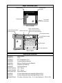
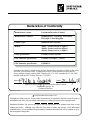
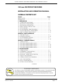
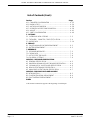
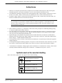
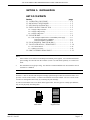

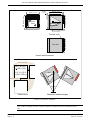
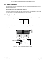
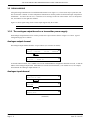
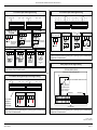
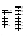
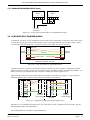
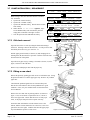
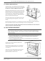

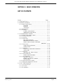
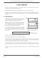
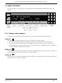
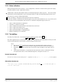
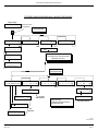

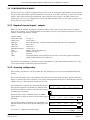
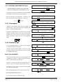
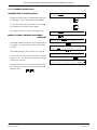
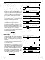
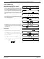
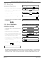
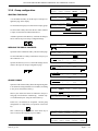
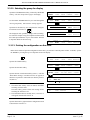
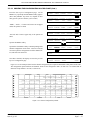


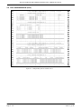
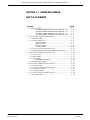

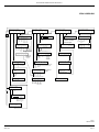

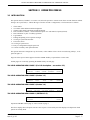
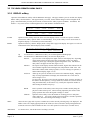
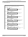
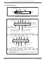
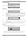
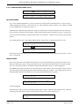
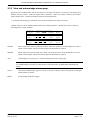
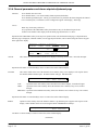
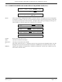
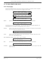
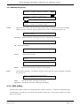
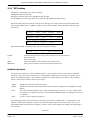
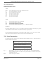
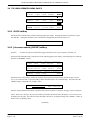
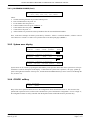
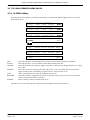
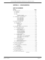
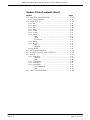
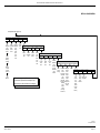

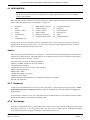
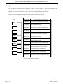
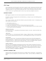
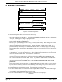
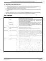
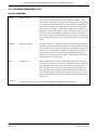
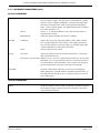
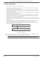
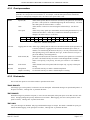
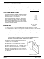
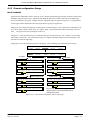
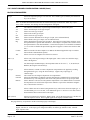
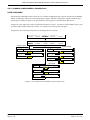
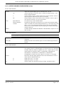
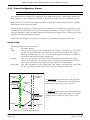

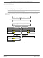
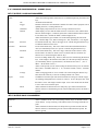
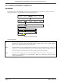
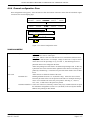
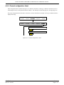
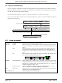
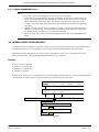
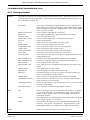
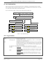
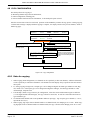
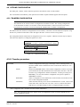
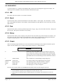


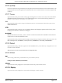
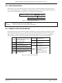


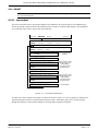
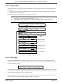
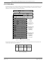

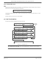

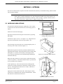
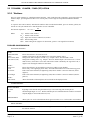
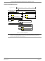
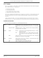
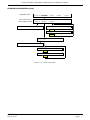
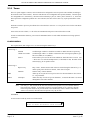
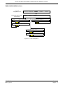
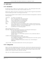
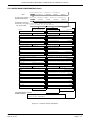
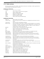
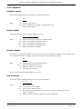
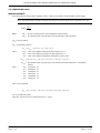
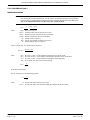
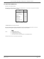
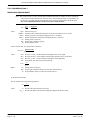

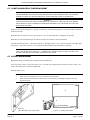
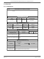
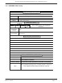
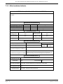
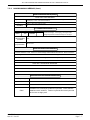
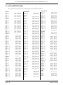
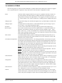
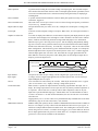
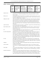
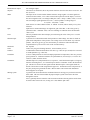
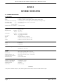
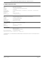
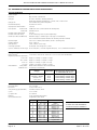
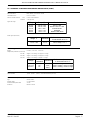
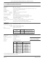


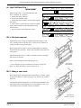
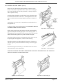
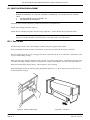
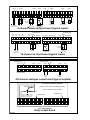


![90X Vol.1 - FAST CORPORATION[株式会社ファースト]](http://vs1.manualzilla.com/store/data/006572316_2-31c9d13a2ca22e21ebe1d6efc2b1adfa-150x150.png)

![取扱説明書 - FAST CORPORATION[株式会社ファースト]](http://vs1.manualzilla.com/store/data/006553029_2-eb0c49d009e589a1095e13b0feb67f2c-150x150.png)