1
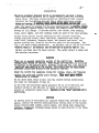
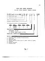
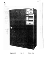
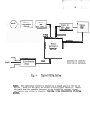
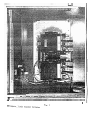
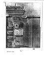
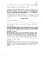
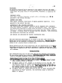
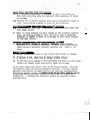
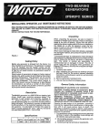
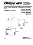
INSTALLATION, OPERATION, and MAINTENANCE INSTRUCTIONS
OWNERS MANUAL
MODELS COVERED BY THIS MANUAL
E6OATS THROUGH E400ATS
and
(UL 1008 Approved)
UE6OATS THROUGH UE400ATS
FORM 1170 10771
TABLE
OF
..
CONTENTS
Introduction
Warning
Service
Warranty
..
Ins t a 1 l a t i o n
Operat i o n
Optional Features
Maintenance
Troubleshooting
LIST
OF
ILLUSTRATIOXS
Fig. 1
ModelNumber~esi~nationTable
Fig. 2
Complete ATS, External View
Fig. 3
Control Box I n t e r i o r , Contactor S h i e l d i n P l a c e
Fig. 4
Typical Block Wiring Diagram
Fig. 5
ATS E x t e r n a l W i r i n g A c c e s s
Fig. 6
200 Ampere, 3 P o l e Transfer Contactor
Fig. 7
. ATS Control Panel
Page
4
The Winco Automatic T r a n s f e r Switch i s d e s i g n e d f o r u s e w i t h a remote
s t a r t t y p e e n g i n e g e n e r a t o r s e t t o s u p p l y s t a n d b y power when t h e prime
s o u r c e f a i l s . The b a s i c s y s t e m c o n t a i n s a n e l e c t r i c a l l y h e l d t r a n s f e r
c o n t a c t o r f o r t r a n s f e r r i n g t h e load from a prime s o u r c e t o a standby
s o u r c e and r e t u r n . A c o n t r o l r e l a y s e n s e s prime power f a i l u r e and
i n i t i a t e s t h e e n g i n e s t a r t i n g sequence. When prime power i s a g a i n a v a i l a b l e , t h e e n g i n e i s s t o p p e d .and t h e l o a d r e t r a n s f e r r e d . A b a t t e r y c h a r g e r
w i t h a u t o m a t i c t a p e r e d c h a r g e , and c h a r g e r a t e ammeter keeps t h e cranking
b a t t e r y a t f u l l charge. A s e l e c t o r s w i t c h , t e s t s w i t c h , s t o p cranking
r e l a y , p i l o t l i g h t s , and o v e r cranking r e l a y a r e p a r t of t h e b a s i c package.
v
Factory wired options include mechanically held t r a n s f e r c o n t a c t o r s ,
v o l t a g e s e n s i t i v e r e l a y s , s t a r t t i m e d e l a y , r e t r a n s f e r t i m e d e l a y , exerc h e r c l o c k , v o l t m e t e r , frequency meter, and e l a p s e d time meter. Any
o p t i o n s s u p p l i e d a r e l i s t e d on t h e f a c t o r y o r d e r f o r t h e equipment. See
,An e x t e r n a l view of t h e ATS w i t h t h r e e
F i g . 1 f o r model number d e s i g n a t i o n .
o p t i o n a l meters i n a d d i t i o n t o t h e s t a n d a r d b a t t e r y c h a r g e ammeter i s
shown i n F i g . 2. .An i n t e r n a l view of t h e ATS i s shown i n F i g . 3. A l l
o p t i o n s a r e shown p l u s t h e b a s i c c o n t r o l . The s a f e t y s h i e l d i s shown o v e r
the t r a n s f e r contactors.
WARNING
There a r e no exposed c o n d u c t o r s o u t s i d e o f t h e c o n t r o l box. Hazardous
v o l t a g e exist i n s i d e o f t h e box. Even though a l l t e r m i n a l s a r e p r o t e c t e d
by b a r r i e r s t o t h e maximum e x t e n t p o s s i b l e i n s i d e t h e box, c a r e should b e
e x e r c i s e d when working on t h e c o n t r o l . Only a u t h o r i z e d and experienced
p e r s o n n e l should have a c c e s s t o t h e i n s i d e o f t h e box.
Check t h e c o n t r o l box nameplate r a t i n g f o r v o l t a g e , phase, and frequency
a g a i n s t t h e prime and s t a n d b y power r a t i n g s . They must a g r e e b e f o r e
installation is started.
Do n o t a l l o w metal c h i p s t o f a l l i n t o t h e c o n t r o l d u r i n g i n s t a l l a t i o n ;
b u t c l e a n o u t t h o r o u g h l y i f t h e y do.
A t any time t h e a s s o c i a t e d e n g i n e g e n e r a t o r s e t i s t o b e s e r v i c e d , t h e
s e l e c t o r s w i t c h i n t h e ATS must b e t u r n e d t o t h e "off" p o s i t i o n t o
p r e v e n t a n unexpected e n g i n e s t a r t . R e s t o r e t o t h e "auto" p o s i t i o n a f t e r
servicing.
SERVICE
If s e r v i c e . p a r t s o r a s s i s t a n c e a r e r e q u i r e d beyond t h a t provided i n t h i s
manual, c o n s u l t t h e n e a r e s t a u t h o r i z e d Winco s e r v i c e shop o r t h e f a c t o r y .
Always f u r n i s h model number, s e r i a l number, and r a t i n g when r e q u e s t i n g
s e r v i c e . Claims f o r s h i p p i n g damage s h o u l d b e made d i r e c t l y t o t h e t r a n s p o r t a t i o n company.
W INC0
U/L 1008
U/L-1008 l i s t e d E
M
- Electrically
- Mechanically
MODEL
NUMBER
DESIGNATION
LISTED AUTOMATIC
-
?
U
E
200
ATS
T.~ANSFER
-
17 M
SWITCHES
/ A
1245689
held
held
Ampere r a t i n g
Automatic t r a n s f e r s w i t c h
2
~ o l t s / p h a s e / w i r e s / ~ o l ecode
s
Code
3
Volts
1201240
Phase
1
Wires
3
Poles
2
!
Engine C o n t r o l :
M = magneto, 12 V DC
B = b a t t e r y , s p a r k & d i e s e l , 12 V DC
1
Design i s s u e , a l p h a b e t i c a l l y
!
Opt i o n s :
1.
2.
4.
5.
6.
8.
9.
R e t r a n s f er d e l a y ( i n c l u d e s o v e r r i d e s w i t c h )
s t a r t delay
Exerciser clock
V o l t a g e s e n s i t i v e r e l a y s (one on 1 p h a s e , t h r e e on 3 phase)
Voltmeter
.
Running t i m e meter
Frequency meter
Fig. 1
'
Complete ATS
Fig.
2
Ext erna 1 View
. .-.-,- .. ---.
C o n t r o l Box I n t e r i o r
.----.m
I
'-&
El
Fig. 3
C o n t a c t o r S h i e l d i n Place
12 MONTH
Limited Warranty
WINCO, Incorporatedwarrantsto the orlglnal purchaserfor 12 months that goods manufacturedor supplled by itwill be free from defects
In workmanshlp and.materia1, provided such goods are Installed, operated and maintained In accordance with WlNCO written Instructions.
WINCO's sole liability, and Purchaser's sole remedy for a failure under this warranty, shall be limited to the repair of the product. At
WINCO's option, materlal found to be defective In material or workmanshlp under normal use and service will be repaired or replaced. For
warranty service, return the product within 12 months from the date of purchase, transportation charges prepaid, to your nearest WlNCO
Authorized Service Center or to WINCO, INC. at Le Center Minnesota.
THERE IS NO OTHER EXPRESS WARRANTY.
To the extent permittedby law, any and all warranties, Including those of merchantability and fitness for a particular purpose, are limited
to 12 months from date of purchase. In no event Is WlNCO liable for Incidentalor consequential damages.
Note: Some states do not allow Ilmitatlon on the duration of implied warranty and some states do no allow the exclusion orlimltaiion
oflncldentalorconsequenflaldamages,so the above llmitatlons may not apply in every Instance. Thls wanantyglves you specific legal rights
which may vary from state to state.
WlNCO reserves the right to change or Improve its products without incurring any obligations to make such changes or Improvement
on products purchased previously.
EXCLUSIONS:
WlNCO does not warrant engines, batteries, or other component parts that are warranted by their respective manufacturers.
WlNCO does not warrant rnodiflcationsor alterations which were not made by WINCO, INC.
WlNCO does not warrant products which have been subjected to misuse and/or negligence or have been Involved in an accident.
This warranty does not Include travel time, mileage, or labor for removal or reinstallation of WlNCO product from its application.
INSTALLATION
LOCATION: The c o n t r o l s h o u l d b e l o c a t e d i n a c l e a n , d r y , i n d o o r p l a c e
n e a r t h e g e n e r a t o r . It must b e mounted on a s o l i d v e r t i c a l s u r f a c e w h i c h
i s r e l a t i v e l y f r e e of v i b r a t i o n . E l e c t r i c a l l y h e l d c o n t a c t o r s may p r o d u c e a n a u d i b l e hum, which can b e minimized by c a r e f u l i n s t a l l a t i o n . Avoid
mounting on a t h i n w a l l which may p r o d u c e a s o u n d i n g board e f f e c t . Allow
room f o r t h e d o o r , h i n g e d on t h e r i g h t s i d e , t o swing open a minimum o f
135O f o r e a s e i n c o n n e c t i n g and s e r v i c i n g .
CODES: W i r i n g must conform t o a p p l i c a b l e e l e c t r i c a l codes. S e p a r a t e
c o n d u i t o p e n i n g s must b e c u t i n t h e m e t a l box f o r t h e l i n e , l o a d , g e n e r a t o r
a n d c o n t r o l l e a d s . A f l e x i b l e s e c t i o n of c o n d u i t i s r e q u i r e d a t t h e
g e n e r a t o r t o absorb g e n e r a t o r set v i b r a t i o n .
LAYOUT:
A t y p i c a l w i r i n g d i a g r a m i s shown i n b l o c k format i n F i g . 4
1- I
Ckt. Brkr.
I
Ckt. Brkr.
I f Reqd.
1
Engine
GENERATOR
LINE
CONTROL
I
Winco
Automatic
Transfer
Switch
Loads
t
I
Distribution
Panel
Fig. 4
LOAD
L o c a t i o n of c o n d u i t s
i n t o box i s o p t i o n a l .
T y p i c a l Wiring System
PANEL: The s u p e r v i s o r y c o n t r o l i s mounted on a hinged p a n e l a t t h e t o p of
t h e box. Swing o u t t h e p a n e l f o r a c c e s s t o w i r i n g s p a c e behind i t . Remove
t h e guard over , t h e t r a n s f e r c o n t i c t o r a t t h e bottom f o r t e r m i n a l a c c e s s ,
and r e p l a c e when w i r i n g i s complete. S e e F i g . 5 f o r i l l u s t r a t i o n of w i r i n g
access.
WIRING: The l o a d c u r r e n t c a r r y i n g wires must b e of a d e q u a t e s i z e t o c a r r y
r a t e d c u r r e n t . I f aluminum c o n d u c t o r s a r e p r e f e r r e d , check marking on cont a c t o r t e r m i n a l s t o make c e r t a i n t h a t t h e y a r e r a t e d f o r aluminum a s w e l l
a s copper conductors. See F i g . 6 f o r i l l u s t r a t i o n of 200 ampere, 3 p o l e
t r a n s f e r c o n t a c t o r . The c o n t r o l w i r e s may b e # I 6 o r l a r g e r f o r any d i s t a n c e up t o 100 f e e t . They connect t h e c o n t r o l ' t e r m i n a l s t r i p i n t h e
t r a n s f e r c o n t r o l box t o a s i m i l a r l y marked t e r m i n a l s t r i p i n t h e g e n e r a t o r
s e t c o n t r o l box;
PROTECTION: C i r c u i t p r o t e c t i o n must b e .provided a s r e q u i r e d . The prime
power s o u r c e should b e p r o t e c t e d ( f u s e s o r c i r c u i t b r e a k e r ) f o r t h e r a t i n g
of t h e s e r v i c e o r of t h e t r a n s f e r c o n t a c t o r , whichever i s lower. The i n p u t
from t h e g e n e r a t o r should b e p r o t e c t e d f o r t h e r a t i n g of t h e g e n e r a t o r o r
t h e t r a n s f e r c o n t a c t o r , whichever i s lower. I f a p p l i c a b l e codes permit
and t h e g e n e r a t o r i s i n h e r e n t l y p r o t e c t e d o r h a s i t s own c i r c u i t b r e a k e r o r
fuses of thelcorrect r a t i n g , additional protection is not required. A
manual d i s c o n n e c t s w i t c h should be p l a c e d i n t h e l i n e between t h e meter and
t h e t r a n s f e r switch.
INSTALLATION
-
Sequence of I n s t a l l a t i o n :
1. Mount t h e c o n t r o l box.
Disconnect e n g i n e c r a n k i n g b a t t e r y .
2.
Connect t h e g e n e r a t o r power l e a d s t o t h e u p p e r t e r m i n a l s on t h e c o n t a c t o r
marked "GEN."
3.
Connect t h e c o n t r o l l e a d s between c o n t r o l box and g e n e r a t o r .
4.
Connect t h e l o a d l e a d s t o t h e bottom t e r m i n a l s on t h e c o n t a d t o r . The
t y o c o n t a c t o r s a r e f a c t o r y i n t e r w i r e d on t h e load s i d e , and one s e t
of terminals is provided.
.-
5.
Connect t h e prime power l e a d s t o t h e upper t e r m i n a l s on t h e c o n t a c t o r
marked "LINE".
6.
Connect t h e b a t t e r y t o t h e e n g i n e g e n e r a t o r s e t a s i n s t r u c t e d w i t h t h e
set.
7.
Note: The n e u t r a l from l i n e , l o a d , and g e n e r a t o r i s unswitched and
should b e s o l i d l y interconnected.
U s e i n s u l a t e d n e u t r a l terminal.
8.
I f a remote t e s t s w i t c h i s t o b e u s e d , remove t h e jumper on t h e twop o i n t t e r m i n a l s t r i p on t h e r i g h t hand s i d e of t h e p a n e l and r u n two
816 w i r e s t o a n o n / o f f t o g g l e s w i t c h .
LA&.
200 Amnere, 3 P o l e T r a n s f e r C o n t a c t o r
U
.
a.
k.
OPERATION
STALLA AT ION CHECKS :
The s t a n d b y system s h o u l d b e ' c h e c k e d a f t e r t h e e n g i n e g e n e r a t o r s e t h a s
b e e n i n s t a l l e d i n a c c o r d a n c e w i t h t h e i n s t r u c t i o n s f o r t h e s e t and t h e
A u t o m a t i c T r a n s f e r S w i t c h h a s been i n s t a l l e d p e r t h i s i n s t r u c t i o n manual.
S e e F i g . 7 f o r c o n t r o l p a n e l l a y o u t . Proceed w i t h t h e c h e c k i n g sequence
a s follows:
1.
S e t t h e s e l e c t o r s w i t c h on " S t o p t t . The s e l e c t o r s w i t c h i s t h e t h r e e
p o s i t i o n s w i t c h i n s i d e t h e c o n t r o l box.
2.
Connect t h e e n g i n e c r a n k i n g b a t t e r y , i f i t h a s n o t p r e v i o u s l y been
c o n n e c t e d . I f t h e ATS was e n e r g i z e d b e f o r e c o n n e c t i n g t h e b a t t e r y ,
t h e b a t t e k y c h a r g e r would c a u s e h a z a r d o u s s p a r k i n g a t t h e b a t t e r y
t e r m i n a 1.
3.
C l o s e t h e c i r c u i t b r e a k e r o r manual s w i t c h i n t h e l i n e l e a d i n g from
t h e p r i m e s o u r c e t o t h e ATS. The l i n e c o n t a c t o r s h o u l d c l o s e and f e e d
power t o t h e l o a d .
I f a r e t r a n s f e r time delay i s included a s an
o p t i o n i n t h e ATS, move t h e r e t r a n s f e r d e l a y o v e r r i d e t o g g l e s w i t c h
momentarily t o t h e "0.R." ( o v e r r i d e ) p o s i t i o n t o c l o s e t h e l i n e contactor.
4.
T u r n t h e s e l e c t o r s w i t c h t o "Check".
The e n g i n e s h o u l d s t a r t and r u n .
T h e c r a n k i n g c i r c u i t i s a u t o m a t i c a l l y d e - e n e r g i z e d a s t h e e n g i n e comes
up t o r a t e d s p e e d . Check g e n e r a t o r v o l t a g e .
5.
T u r n t h e s e l e c t o r s w i t c h t o "Auto".
6.
When i n s t a l l i n g a t h r e e phase t r a n s f e r p a n e l , b e s u r e t o check p h a s e
r o t a t i o n on t h e l o a d l i n e s w i t h p r i m e power, a n d t h e n s t a n d b y power.
U s e a p h a s e r o t a t i o n t e s t e r o r a t h r e e p h a s e motor.
I f phase r o t a t i o n
i s wrong, i n t e r c h a n g e any two l e a d s o f t h a t s u p p l y
not t h e load
leads.
Engine w i l l s t o p .
-
7.
S i m u l a t e a power f a i l u r e by moving t h e t e s t t o g g l e s w i t c h t o "Test".
The l i n e c o n t a c t o r opens and t h e e n g i n e w i l l s t a r t when t h e t e s t
I f a s t a r t d e l a y r e l a y i s i n c l u d e d a s an o p t i o n ,
switch is operated.
t h e e n g i n e w i l l n o t s t a r t f o r t h i s t i m e i n t e r v a l , n o r m a l l y 2.5 t o
15 seconds. The g e n e r a t o r v o l t a g e w i l l come up t o r a t e d v a l u e and
t h e "Gen." c o n t a c t o r w i l l c l o s e . The l o a d i s now s u p p l i e d by t h e
generator.
8.
R e t u r n t h e t e s t s w i t c h t o "Autott. The e n g i n e w i l l s t o p and t h e t r a n s f e r c o n t a c t o r w i l l t r a n s f e r t h e l o a d from t h e g e n e r a t o r t o t h e p r i m e
source. Refer back t o s t e p 3 i f a r e t r a n s f e r d e l a y is included.
9.
Check c h a r g e r a t e on t h e b a t t e r y c h a r g e ammeter. It s h o u l d r e a d two
amperes i f t h e b a t t e r y i s low and a u t o m a t i c a l l y t a p e r towards z e r o
'as f u l l c h a r g e i s r e a c h e d .
.
10.
I f a n e x e r c i s e r c l o c k i s included as a n o p t i o n , s e t t h e time of day
on t h e l a r g e d i a l . S e t t h e day of t h e week on t h e s m a l l d i a l , l a ~ e r
l e f t . T h i s i s a 14 day d i a l and p i n s are o m i t t e d f o r each Monday.
Change p i n s i n t h i s d i a l ' t o choose a n o t h e r day f o r e x e r c i s e . ' These
p i n s have a l e f t - h a n d t h r e a d . The t i m e a t which t h e set i s t o b e
e x e r c i s e d i s s e t f o r 9:00 t o 9:15 A.M.
R e s e t t h e l e f t - h a n d threaded
p i n s i n t h e l a r g e d i a l f o r a d i f f e r e n t e x e r c i s e time. The i n n e r
c i r c l e s t a r t s and t h e o u t e r c i r c l e s t o p s t h e e x e r c i s e .
E x e r c i s e p e r i o d s of 15 t o 30 minutes once a week a r e recommended. The
load is not transferred t o t h e generator during exercise unless a
power f a i l u r e o c c u r s .
11.
I f a n e x e r c i s e r c l o c k i s n o t i n c l u d e d i n t h e ATS, t h e e n g i n e g e n e r a t o r
s e t should b e s t a r t e d and run a t weekly i n t e r v a l s f o r 15 t o 30
.
minutes. S e t t h e s e l e c t o r s w i t c h a t "Check" t o o p e r a t e t h e engine.
R e t u r n se1:ector t o "Auto" a t end of e x e r c i s e .
12.
CAUTION: Always t u r n s e l e c t o r s w i t c h t o "Off" b e f o r e s e r v i c i n g t h e
e n g i n e , g e n e r a t o r , o r t h e ATS.
NORMAL OPERATION - BASIC CONTROL:
A s t a r t / s t o p r e l a y i s e n e r g i z e d when prime power i s a v a i l a b l e . When t h i s
r e l a y i s de-energized upon prime power f a i l u r e , t h e engine s t a r t i n g sequence
i s i n i t i a t e d . The e n g i n e w i l l crank u n t i l it starts, o r u n t i l t h e overc r a n k i n g r e l a y opens t h e c r a n k i n g c i r c u i t i n 60 seconds. The over cranking
r e l a y i s mounted i n t h e door o f t h e c a b i n e t . It h a s a r e d r e s e t b u t t o n
which must b e pushed in t o r e s t o r e t h e c r a n k i n g c i r c u i t , i n t h e e v e n t t h e
r e l a y h a s functioned. I f engine f a i l s t o s t a r t a f t e r s e v e r a l attempts,
r e f e r t o t h e g e n e r a t o r s e t s e r v i c e manual f o r c o r r e c t i v e a c t i o n .
On t h r e e phase systems a phase f a i l u r e r e l a y i s used i n c o n j u n c t i o n w i t h
t h e s t a r t / s t o p r e l a y t o a s s u r e t h e t r a n s f e r o p e r a t i o n i f any phase f a i l s .
When t h e prime power f a i l s , i t a l s o d e - e n e r g i z e s t h e l i n e c o n t a c t o r t o
d i s c o n n e c t t h e l i n e from t h e load. T h i s c o n t a c t o r i s mechanically and
e l e c t r i c a l l y i n t e r l o c k e d w i t h t h e g e n e r a t o r c o n t a c t o r s o t h a t only one cont a c t o r of t h e t r a n s f e r c o n t a c t o r s c a n b e c l o s e d a t one time. T h i s i s
e s s e n t i a l s o t h a t t h e g e n e r a t o r cannot b e connected t o t h e l i n e under any
circumstances.
A s t h e e n g i n e r e a c h e s o p e r a t i n g speed, t h e g e n e r a t o r r e a c h e s o p e r a t i n g
v o l t a g e . T h i s v o l t a g e i s a p p l i e d t o t h e s t o p c r a n k i n g r e l a y , which c l o s e s
and d e - e n e r g i z e s t h e e n g i n e c r a n k i n g c i r c u i t . T h i s same v o l t a g e i s
a p p l i e d t o t h e g e n e r a t o r c o n t a c t o r , which c l o s e s and connects t h e load t o
the generator.
The t h r e e p o s i t i o n s e l e c t o r s w i t c h p e r m i t s t h e e n g i n e t o b e stopped, run
f o r a check w i t h o u t l o a d t r a n s f e r , o r set f o r a u t o m a t i c o p e r a t i o n . T h i s i s
d e s c r i b e d i n t h e i n s t a l l a t i o n check above.
-
Fig. 7
ATS C o n t r o l Panel
A t e s t t o g g l e s w i t c h can s i m u l a t e a l i n e power f a i l u r e by d e - e n e r g i z i n g
t h e t o t a l l i n e c o n t r o l c i r c u i t . The e n g i n e w i l l s t a r t and t h e load w i l l
t r a n s f e r t o t h e g e n e r a t o r when t h e t o g g l e s w i t c h i s moved t o t h e " t e s t "
p o s i t i o n . R e t u r n i n g t h e s w i t c h t o "normal" r e s t o r e s t h e normal standby
c o n d i t i o n w i t h t h e l i n e power supplying t h e load.
An a u t o m a t i c t a p e r e d b a t t e r y c h a r g e r w i l l supply a two ampere c h a r g e t o a
low b a t t e r y and t a p e r t o almost z e r o a t f u l l c h a r g e . The primary of t h e
t r a n s f o r m e r i s p r o t e c t e d by a f u s e and t h e r e c t i f i e d o u t p u t has an a u t o m a t i c r e s e t c i r c u i t b r e a k e r f o r a d d i t i o n a l p r o t e c t i o n . A DC ammeter on
t h e p a n e l i n d i c a t e s t h e a c t u a l charge c u r r e n t .
P i l o t l i g h t s a r e p r o v i d e d t o i n d i c a t e power s o u r c e b e i n g used. The long
l i f e g a s d i s c h a r g e p i l o t l i g h t s i n d i c a t e g r e e n f o r prime power t o t h e l o a d ,
o r r e d f o r standby power. The extended l e n s makes them v i s i b l e through a
wide a n g l e .
OPTIONAL FEATURES
VOLTAGE SENSITIVE RELAYS:
One t o t h r e e v o l t a g e s e n s i t i v e r e l a y s may b e f u r n i s h e d i n t h e prime power
supply l i n e t o s e n s e a v o l t a g e drop. They w i l l open t h e c o n t r o l c i r c u i t
and i n i t i a t e t h e t r a n s f e r t o standby power a t a p r e - s e t v o l t a g e . The dropo u t and pick-up v o l t a g e s a r e p r e - s e t a t t h e f a c t o r y b u t can be a d j u s t e d
a f t e r i n s t a l l a t i o n . 'They permit a f i n e r c o n t r o l of t h e standby system.
START DELAY RELAY :
The s t a r t d e l a y r e l a y p r e v e n t s s t a r t i n g of t h e e n g i n e f o r a p e r i o d up t o
60 s e c o n d s a f t e r power f a i l u r e . It i s f a c t o r y s e t f o r 2.5 t o 15 seconds
but can-be adjusted a f t e r installation.
It p r e v e n t s n u i s a n c e s t a r t i n g of
t h e e n g i n e u n t i l t h e prime power h a s been u n a v a i l a b l e f o r t h e time i n t e r v a l t h e timer is set for.
RETRANSFER DELAY RELAY :
The r e t r a n s f e r d e l a y r e l a y i s a motor d r i v e n t i m e r t o p r o v i d e up t o 30
minutes t i m e d e l a y i n t h e shutdown of t h e e n g i n e and t h e r e t r a n s f e r of
t h e l o a d a f t e r t h e prime power i s a v a i l a b l e . It i s a d j u s t e d f o r 1 5
m i n u t e s d e l a y a t t h e f a c t o r y but can b e r e - a d j u s t e d a f t e r i n s t a l l a t i o n .
It p r e v e n t s n u i s a n c e e n g i n e s t o p s and l o a d r e t r a n s f e r u n t i l prime power
h a s b e e n a s s u r e d f o r t h e p r e - s e t time. An o v e r r i d e t o g g l e switch i s used
i n c o n j u n c t i o n w i t h t h e t i m e r . When t h e momentary c o n t a c t t o g g l e s w i t c h
i s moved t o t h e r e t r a n s f e r p o s i t i o n , t h e t r a n s f e r i s immediately accomp l i s h e d and t h e e n g i n e stopped.
EXERCISER CLOCK:
This. o p t i o n w i l l a u t o m a t i c a l l y s t a r t , r u n f o r 1 5 m i n u t e s , and s t o p t h e
e n g i n e g e n e r a t o r s e t . It can be s e t f o r any t i m e , time i n t e r v a l , and day
It i s e s s e n t i a l t h a t e n g i n e s b e r u n a t l e a s t once a week
of t h e week.
t o i n s u r e a r e l i a b l e system, whether t h e y be c o n t r o l l e d by a c l o c k o r
rnanua 1l y
.
VOLDETER:
An o p t i o n a l v o l t m e t e r can b e mounted i n . t h e c o n t r o l box door. It w i l l
i n d i c a t e t h e load v o l t a g e
240 v o l t s s i n g l e phase o r one o f t h r e e phases
from e i t h e r t h e prime s o u r c e o r t h e g e n e r a t o r , whichever i s s u p p l y i n g t h e
load.
-
FREQUENCY METER:
T h i s meter i n d i c a t e s frequency i n H e r t z w i t h a v i b r a t i n g r e e d .
mounted i n t h e c o n t r o l box d p o r .
RUNNLNG TIHE METER:
T h i s o p t i o n i n d i c a t e s t o t a l h o u r s of e n g i n e g e n e r a t o r o p e r a t i o n .
mounted i n t h e c o n t r o l box door.
-
It i s
It i s
MECHANICALLY HELD TRANSFERCONTACTOR:
The e l e c t r i c a l l y h e l d t r a n s f e r c o n t a c t o r can b e r e p l a c e d w i t h a mechanica l l y h e l d t r a n s f e r c o n t a c t o r , b o t h l i n e and g e n e r a t o r s i d e s . The c o n t a c t o r
i s e l e c t r i c a l l y o p e r a t e d t o e i t h e r c l o s e and l a t c h , o r u n l a t c h and open.
T h e r e i s no n o i s e o r h e a t g e n e r a t e d o r any power l o s s when e i t h e r c o n t a c t o r
i s c l o s e d . A c o n t r o l r e l a y i s i n c l u d e d w i t h t h e c o n t a c t o r . Both e l e c t r i c a l
a n d mechanical i n t e r l o c k s a r e provided.
A l l options a r e a v a i l a b l e f o r f a c t o r y i n s t a l l a t i o n only.
MAINTENANCE
The m o s t ' e s s e n t i a l maintenance i s t o a s s u r e a d r y and c l e a n c o n t r o l box.
Water must n e v e r b e a l l o w e d t o d r i p on t h e c o n t r o l box. I f d u s t and d i r t
a c c u m u l a t e i n t h e i n t e r i o r , d e - e n e r g i z e t h e c i r c u i t s and b r u s h o r wipe
c l e a n o r u s e a s u c t i o n h o s e t o remove d i r t .
Check p e r i o d i c a l l y f o r l o o s e ~ c o n n e c t i o n sand any d e t e r i o r a t i o n of c o n t a c t s .
Any damage c o u l d o n l y b e caused by e x t e r n a l o r i n t e r n a l m a l f u n c t i o n . The
h i g h q u a l i t y components and t h e i r c o n s e r v a t i v e a p p l i c a t i o n keep maintenance
a t a minimum.
TROUBLESHOOTING
Any t r o u b l e s h o o t i n g must b e done w i t h t h e u s e and thorough u n d e r s t a n d i n g
o f t h e w i r i n g d i a g r a m and schematic. S e r v i c i n g u n d e r any o t h e r c o n d i t i o n s
c o u l d b e extremely hazardous t o p e r s o n n e l and p r o p e r t y .
Engine ~ o e s nt' S t a r t On T e s t O r A t Time Of Power F a i l u r e
I f engine d o e s n ' t s t a r t
a) Try t o s t a r t e n g i n e a t e n g i n e c o n t r o l p a n e l .
h e r e , t r o u b l e i s n o t i n t h e ATS.
b)
c)
I f engine s t a r t s i n
t h e selector switch
over cranking r e l a y
DC c r a n k i n g c o n t r o l
.
t r o u b l e is i n w i r i n g t o o r i n t h e ATS. S e t
i n lrcheck" p o s i t i o n and p r e s s r e s e t b u t t o n i n
on door of box. Next check w i r i n g of low v o l t a g e
c i r c u i t p e r w i r i n g diagrams.
"a",
I f e n g i n e s t a r t s i n llcheck" p o s i t i o n b u t n o t i n l1auto1I p o s i t i o n w i t h
t e s t s w i t c h i n "test" p o s i t i o n , t h e s t a r t i s t o p r e l a y i s d e f e c t i v e .
Repair o r replace.
Engine won' t S t o p When Prime Power R e t u r n s
a ) I f a r e t r a n s f e r t i m e d e l a y i s i n c l u d e d , b e s u r e i t h a s timed o u t .
Then check s t a r t / s t o p r e l a y and e x e r c i s e r c l o c k o p e r a t i o n , i f l a t t e r
i s included.
b)
T e r m i n a l "A" on c o n t r o l t e r m i n a l s t r i p must b e grounded f o r engine t o
s t o p . Follow w i r i n g diagrams t o check f o r t h i s c o n d i t i o n .
----
L i n e C o n t a c t o r Won't C l o s e When Prime S o u r c e I s A v a i l a b l e
a ) I f a r e t r a n s f e r t i m e d e l a y i s i n c l u d e d , ~ G r a t er e t r a n s f e r d e l a y overr i d e toggle switch.
b)
R e f e r t o w i r i n g diagrams and check v o l t a g e a t l i n e c o n t a c t o r o p e r a t i o n
coil.
I f t h e r e i s v o l t a g e a t c o i l , t h e c o i l i s open o r mechanical
i n t e r l o c k i s jmmed.
I f t h e r e i s no v o l t a g e a t c o i l , check c i r c u i t s
t o f i n d open c i r c u i t .
G e n e r a t o r C o n t a c t o r Won' t C l o s e When G e n e r a t o r Is Runnin
If o
: voltage,
a ) Check g e n e r a t o r v o l t a g e a t c o n t a c t o r t e r m i n x s .
generator or its wiring is defective.
I f there is generator voltage,
c h e c k v o l t a g e a t g e n e r a t o r c o n t a c t o r o p e r a t i n g c o i l . R e f e r t o (b)
above.
B a t t e r y D o e s n ' t Charge
a ) C h a r g e r a u t o m a t i c a l l y g o e s t o z e r o c u r r e n t when b a t t e r y i s charged.
b)
I f b a t t e r y is low, check f u s e in c h a r g e r primary c i r c u i t ' .
c)
I f 120 v o l t s AC i s a p p l i e d t o t h e t r a n s f o r m e r and t h e r e i s no DC o u t p u t ,
r e p l a c e t h e c h a r g e r u n l e s s some obvious r e p a i r can b e made.
I f any o t h e r m a l f u n c t i o n e x i s t s , r e f e r t o t h e w i r i n g diagrams. Note t h a t
t h e s c h e m a t i c shows t h e c i r c u i t s groubed by f u n c t i o n ; l i n e s i d e c o n t r o l ,
g e n e r a t o r s i d e c o n t r o l , DC engine c o n t r o l , and l o a d s i d e i n s t r u m e n t a t i o n
and b a t t e r y c h a r g e r c o n t r o l . A c a r e f u l s t u d y of any o t h e r symptoms and t h e
w i r i n g d i a g r a m s should e n a b l e a q u a l i f i e d e l e c t r i c i a n t o c o r r e c t any
m a l f u n c t i o n . A v o l t m e t e r and c o n t i n u i t y c h e c k e r a r e e s s e n t i a l t r o u b l e shooting tools.
-
I
2
GENERATOR
RELAY
IF b d
I
I
THREE
PHASE CIRCUIT
I
OMIT
-
I5
IF . T O R "
USED
.
-
GENERATOR
IND:CATOR
m-MP