1
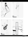
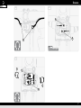
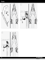
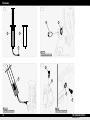
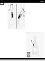
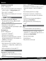
Owner's manual · RT8 TT · RT8 C · RT6 TT · RT6 C THE PASSION PEOPLE www.magura.com Contents Diagrams Introduction Preface................................14 Legend................................14 Technical Specifications Specifications.....................15 Dimensions.........................15 English Safety Intended use.......................16 Basic safety instructions.....16 . Installation Fit the brake........................18 General................................. 18 Mounting brake lever . (RT TT).................................. 18 Mounting the converter . (RT C)................................... 19 Mounting brake cables . (RT C)................................... 19 Changing brake lever . allocation (RT C)................... 20 Shortening brake hose......... 20 Mounting brake shoes.........21 Adjusting brake shoe............ 21 Setting pressure point.........21 On the move Opening the brake for . dis-/mounting the wheel...... 22 Maintenance Regular................................22 Changing brake pads..........23 Retightening brake cables . (RT C)..................................23 Bleeding and filling brake....24 Rules Warranty.............................25 3 Diagrams A1 A2 1 2 B1 1 B2 4 2 8 mm 4 N·m (35 lbf·in) max. 4 ~10 mm THE PASSION PEOPLE www.magura.com Diagrams TD A B 1 C D F E G 5 Diagrams C1 C2 3 1,2 N·m (11 lbf·in) max. D1 D2 2 T20 2 N·m (18 lbf·in) max. 6 20 mm min. THE PASSION PEOPLE www.magura.com Diagrams D3 D4 4 4 1 2 N·m (18 lbf·in) max. D5 1 5 1 5 7 Diagrams E1 F1 1 3 2 2 1 10 mm min. 8 mm 4 N·m (35 lbf·in) max. 5 mm 5 N·m (44 lbf·in) max. G1 G2 18 mm – 22 mm 3 1 23 mm – 28 mm 2 4 5 2 1,5 N·m (13 lbf·in) max. 8 THE PASSION PEOPLE www.magura.com Diagrams H1 3 2 4 mm 7 N·m (62 lbf·in) max. H2 1 1 1 1–1,5 mm 9 Diagrams J1 J2 1 2 1 J3 2 1 10 THE PASSION PEOPLE www.magura.com Diagrams K1 11 Diagrams L1 L2 4 2 5 3 1 3 mm 4 N·m (35 lbf·in) max. L3 L4 2 6 7 7 6 8 mm 4 N·m (35 lbf·in) max. 12 T25 0,5 N·m (4 lbf·in) max. THE PASSION PEOPLE www.magura.com Diagrams L5 3 3 M1 3 13 Introduction Introduction Preface Welcome to the PASSION PEOPLE, You have purchased a powerful, low-maintenance MAGURA RT hydraulic rim brake of the latest generation – designed in Germany. This User Manual is an integral part of your MAGURA product and gives you details of the required tools, correct installation, safe use, maintenance and setup options. Please read this Manual carefully before you install or use your MAGURA product. Always observe and follow all instructions on installation, use and maintenance provided in this Manual and in Manuals by third-party manufacturers whose products you use on your bicycle (headset, stem, handlebar, wheels, etc.). Remember that the mechanic who installs your MAGURA product is responsible for the suitability and compatibility of all the components technically linked to your MAGURA product. Failure to observe the instructions in this Manual can lead to serious or fatal accidents. You can find the diagrams that this Manual refers to in the folder in the front cover. The figures in this Manual may differ slightly from your MAGURA product, however, the required steps are the same for all types and variants – if not stated to the contrary. The type name (1) of your MAGURA brake can be found on one of the two brake arms [TD]. Please note that the braking characteristics of your bicycle may be changed by installation of the new brake. . Familiarize yourself with any changes in the braking characteristics of your bicycle during the first few rides. 14 Legend )) The pointing finger prompts you to perform an action. ÎÎ The arrow shows results or requirements. LLThis notice gives you additional information or tips. refers to an item number in the graphic area – e. g. item ô. [B2] refers to a diagram in the graphic area – e. g. figure B2. (3) This notice warns you about a dangerous situation which can lead to serious or fatal injury if not avoided. This notice warns you about a dangerous situation which can lead to minor or slight injury if not avoided. These notices warn you about the risk of material or environmental damage. Keep this Manual for other users of your MAGURA product. Make sure that each user reads, understands and observes this Manual. If you sell or give away your MAGURA product, be sure to hand over this Manual to the new owner. Please have your MAGURA brake registered online for the 5-year leakproof warranty within thirty days! Visit www.magura.com for more tips and information on your MAGURA product. You can also exchange experiences, ask questions and generally “talk shop” with many PASSION PEOPLE members on the MAGURA Forum. We wish you great success and a great ride Your MAGURA Team THE PASSION PEOPLE www.magura.com Technical Specifications Technical Specifications Specifications RT8 Type name TT hydraulic (MAGURA) Variant Brake lever Brake fluid Time trials, triathlon Applications RT6 C TT Race bike (cable / converter) hydraulic (MAGURA) MAGURA Royal Blood (mineral oil) Street, touring Time trials, triathlon C Race bike (cable / converter) Street, touring Dimensions RT8 Type name Variant TT Ø steerer tube (fork) (A) Thickness of retainer (B) – Retainer angle (C)/ (D)* Ø clamping of brake lever (E) Stud bolts (F) (front/rear) Adjustment dimension (G) (front/rear) TT – C 1⅛" 3 6°/17° 19.55–20.5 28/13 [TD] 47 ± 6 mm Ø brake cable outer sleeve Ø inner brake cable max. Ø brake hose Rim width min.–max. Tyre width max. * RT6 C 1⅛" 3 6°/17° – 5 1.5 – 5 1.5 5 18–28 28 Optional – not included in scope of delivery. 15 Safety Safety Intended use Any use other than the intended use can lead to accidents that cause serious or fatal injury. MAGURA type RT8 TT and RT6 TT rim brakes are designed and intended exclusively –– for installation on standard time trial and triathlon race bikes and the standard time trial or triathlon handlebars. MAGURA type RT8 C and RT6 C rim brakes are designed and intended exclusively –– for installation on standard street and touring race bikes and in combination with standard cable brake levers for caliper brakes. MAGURA rim brakes are designed and intended exclusively –– for use with wheels that have rims with the corresponding brake track areas. –– for the specified application – see Specifications, page 15. MAGURA RT8 and RT6 rim brakes must never be combined and used with components (brake lever, brake body, etc.) of MAGURA disc brakes! Basic safety instructions Always remember that riding a bicycle entails risk both for the rider and other road users, and for the bicycle and its components. . Despite the use of safety gear and complete safety equipment, accidents that cause serious or fatal injury can occur. Always use your common sense and avoid any unreasonable actions! Installation & Maintenance Danger of accident due to damaged brake caused by incorrect or impermissible installation work. –– Never overestimate your technical capabilities. Commission a bicycle workshop or an authorized MAGURA service centre with all installation and maintenance work. This is the only way to ensure that work is conducted in a professional manner. –– Never make any changes (e. g. grinding/painting etc.) to your MAGURA product that are not specifically permitted and described in the user's Manual. –– Always observe all min./max. values stated – see Technical Specifications, page 15. –– For assembly steps that require a specific tightening torque for a screw union, always use a torque wrench set up for the required torque. –– Always maintain your bicycle in technically perfect working order. Danger of accident due to improper accessories. –– Always use MAGURA original parts and lubricants. –– Always use original MAGURA brake shoes and for bleeding and filling use only MAGURA Royal Blood (mineral oil). –– Never use DOT brake fluid. 16 THE PASSION PEOPLE www.magura.com Safety On the Road Danger of accidents due to component failure. Danger of accident due to improper behaviour or improper equipment during riding. –– Before each trip, make sure that the quick release system on your –– Always match your speed to the current road and weather conditions.. wheels is fitted correctly and that your wheels will not work loose. –– Before each trip, make sure your wheels move freely and do not contact the brake pads at any point. –– Before each trip, make sure that the handlebar and stem are correctly fitted and will not twist. –– Before each trip, make sure that both brakes are closed – see Opening the brake for dis-/mounting the wheel, page 22. –– Before each trip, make sure that your brakes operate correctly – the pressure point must be clearly perceptible and does not change when the brake lever is pulled, the brake pads contact the brake track area completely without contacting the tyres. –– Before each trip, make sure that your brakes are not damaged in any way, including with the brake lever pulled (e. g. traces of oil, cracks, etc.). –– Before each trip, make sure that the brake track areas of your wheels and the brake pads have not reached their wear limits and are free from lubricating substances (oil, grease, silicone, wax, etc.). –– After each crash, check your brake for damage and make sure it operates correctly. –– Never use your brake if damage (e. g. traces of oil, cracks, etc.) is visible, you can hear unusual noises or if you have any doubts about its integrity. In this case, have your brake checked in a bicycle workshop or directly by MAGURA Service. Transport & Storage Particularly in wet conditions your braking distance will be significantly increased – always ride cautiously and be ready to brake. –– Always use the front and rear brakes simultaneously. –– Always observe the traffic regulations in the country where you are riding (lighting, reflectors, etc.). –– When riding, always wear a high quality (e.g. ANSI certified), undamaged helmet and clothing that fits snugly but does not impair your actions. –– Only ride your bicycle if you are in good physical condition and your bicycle and all of its components are in perfect working order. Danger of accident due to damaged components. –– Make sure that brake hoses cannot be kinked when you pack your bicycle. –– Do not store your MAGURA brake at temperatures below -15 °C (5 °F) and above 55 °C (131 °F). LLIt is not necessary to drain your MAGURA brake before transporting it by air. Protection of the environment Dispose of used lubricants and oil correctly and in accordance with the legal requirements – never discard them in the sewage system or in the ground. 17 Installation Installation Fit the brake General LLThe following assembly steps always refer to the front wheel brake, but they are identical for the rear wheel brake unless otherwise specified. )) Make sure that the dimensions of the handlebar (Ø clamping of brake lever), fork shaft (Ø converter retainer) and wheels fit your brake – see Technical Specifications, page 15. Danger of accident resulting from restricted or blocked steering movement because brake hose is too short or too long. –– Make sure that there is full steering movement in both directions. –– Keep the length of the brake hose as short as possible and as long as necessary. LLYour MAGURA RT may have been provided with the upgradable Aero cover [A1]. If necessary, you can remove the cover by hand and clip it to the brake arms again later. It is not necessary to unscrew the screws (1) on the guard. LLA thin wire may be helpful for inserting the brake hose into the time- trial handlebar or through the bicycle frame. . Run it in the opposite direction through the outlet to the inlet of the handlebar or frame and fix it to the end of the brake hose with adhesive tape. Do not insert the wire into the brake hose – you will lose oil!. Carefully pulling with the wire and pushing the brake hose at the same time will make it easier to find the outlet. LLBefore installing your brake decide which brake lever (right or left) you want to allocate to your front wheel or rear wheel.. Changing sides – see Changing brake lever allocation (RT C), page 20. LLWhen installing the brake hose for the rear wheel brake use the practi- Oil loss. The brake hose will have to be disconnected from the brake body for some of the following steps. –– Do not actuate the brake lever if the brake hose is disconnected. –– Handle the open brake hose carefully – do not shake it, knock it or hit it. –– Have clean, absorbent and lint-free cloths ready – wipe any leaking oil away immediately. Unusable brake hose – because it is too short. –– Before shortening the brake hose make sure that the handlebar and stem are in their final position and do not need to be raised, extended or adjusted in any way. –– If required, allow a little longer at first – you can always shorten it a bit more but you can't extend it! 18 cal MAGURA hose holder – available in different models. Mounting brake lever (RT TT) Important – see General, page 18! )) Make sure that the pressure point adjusting screws (1) are unscrewed to the stop (-) [H2]. )) Loosen the sleeve nut (1) on the brake body [B1]. )) Pull the brake hose from the brake body. )) Place the brake hose on a solid surface (wood, plastic, etc.) and cut it at right angles immediately behind the olive (2) with a sharp blade – if required, use the MAGURA hose cutter. ÎÎ The olive cannot be used again. )) Insert the brake hose through the time trial handlebar [C1]. )) Attach the brake lever to the time trial handlebar. THE PASSION PEOPLE www.magura.com Installation )) Tighten the clamping screws (3) alternately to a tightening torque of max. 1.2 N·m (11 lbf·in) [C2]. LLThe brake lever can be rotated by hand when forced. It is advantageous if the brake lever can rotate in the event of a fall. This reduces the danger of irreparable damage to the handlebar. Mounting the converter (RT C) )) Mount the converter under the stem on the fork shaft [D1] – use spacers as desired or required. )) Align the stem and converter straight. )) Make sure that the distance between the converter housing and the head tube or headset is at least 20 mm [D2]. ÎÎ The converter cylinder can extend unhindered when the brake opens. LLIf the outlet for the brake cable outer sleeve on the handlebar is inconvenient for a harmonious curve at the stop (1), we recommend positioning the brake cable outer sleeve outside the handlebar and fastening it with insulating tape before winding the handlebar tape. )) Make sure that the brake cable outer sleeves can be positioned in harmonious curves between the handlebar and stops [D3]. )) If required, slide converter onto retainer. )) Tighten retaining screws (2) to a tightening torque of max. 2 N·m (18 lbf·in) [D1]. )) Adjust the headset so that it is free of play. )) Align the stem and converter straight. )) Tighten the clamping screws on the stem to the tightening torque stated by the manufacturer. Mounting brake cables (RT C) LLUse new inner brake cables – this makes installation significantly easier. )) Make sure that the stops (1) are completely screwed in (-) [D3]. )) Make sure that the length of the brake cable outer sleeve is as short as possible (harmonious curves, no kinks) and as long as necessary (ends are fixed in the stops) [D3]. )) Make sure that the ends of the brake cable outer sleeve are clean and smooth. )) Place the brake cable outer sleeve between the brake lever and stop as usual. )) Remove the converter (2) cover by hand [A2]. )) Insert the new inner brake cable, tighten it and fasten it. )) Tighten clamping screw (4) to a tightening torque of max. 2 N·m (18 lbf·in) [D4]. )) Cut off the inner brake cable approx. 8–10 mm behind the clamp with small clippers and clamp on a suitable end sleeve. Danger of accident due to brake failure caused by faulty installation. The stops (1) are intended exclusively for tightening the brake cable [D5]. –– Never attempt to adjust the pressure point of the brake with the stops. –– Make sure that the rockers (5) do not move when you tighten the brake cable with the stops. )) Tighten the brake cable with the stops (1) (+) [D5]. Make sure that the rockers (5) do not move but respond immediately to a pull on the brake lever. LLIt may be necessary to retighten the brake cable after completing in- stallation and adjustment of the brake and the first strong pull on the brake lever – see Retightening brake cables (RT C), page 23. 19 Installation Changing brake lever allocation (RT C) Important – see General, page 18! )) Mark the cut on the brake hose [B2]. )) Place the brake hose on a solid surface (wood, plastic, etc.) and cut at LLIf the connections at the master cylinder are released, the brake must right angles with a sharp blade – if required use the MAGURA hose cutter. )) Remove the brake body from the fork or rear triangle. )) Place the sleeve nut (1) and new olive (2) on the brake hose [B1]. )) Insert the brake hose into the slave cylinder to the stop and hold in position. )) Screw the sleeve nut (1) into the slave cylinder and tighten to a tightening torque of 4 N·m (35 lbf·in) [B1]. )) Make sure that the sleeve nuts (2) of the brake body are long enough [F1]. be refilled on completion – see Bleeding and filling brake, page 24. )) Remove converter (2) cover by hand [A2]. )) Make sure that the pressure point adjusting screws (1) are unscrewed to the stop (-) [H2]. If the brake hose is open at both ends, oil will leak out. –– Place a basin under the end of the hose – before unscrewing the barbe (1)g (1) on the master cylinder (2) [E1]. )) Release barbe (1)g (1) on master cylinder (2) [E1]. )) Screw barbed fitting to desired master cylinder and tighten to a tighten- ing torque of 4 N·m (35 lbf·in). Shortening brake hose Important – see General, page 18! )) Loosen sleeve nut (1) on brake body [B1]. )) Pull the brake hose from the brake body. )) Place brake hose on a solid surface (wood, plastic, etc.) and cut it at right angles immediately behind the olive (2) with a sharp blade – use the MAGURA hose cutter if required. ÎÎ The olive cannot be used again. )) Mount the brake body on the fork or rear triangle – if required, use a serrated washer (1) [F1] – and align vertically – only tighten sleeve nut (2) loosely at this stage. )) Hold the end of the brake hose to the slave cylinder (4) [B2]. Oil loss. –– Do not remove the stud bolts (3) under any circumstances [F1]. )) Install the brake body on the fork or rear triangle – if required use serrated washer (1) [F1] – and align vertically – tighten sleeve nut (2) to a tightening torque of 4–5 N·m (35–44 lbf·in). )) Remove any oil residues thoroughly. )) Pull and hold brake lever. )) Make sure that all connections are tight. Unusable brake hose – because it is too short. –– Calculate the insertion depth (~10 mm) of the brake hose in the slave cylinder (4) [B2]. 20 THE PASSION PEOPLE www.magura.com Installation Mounting brake shoes Setting pressure point Danger of accident due to brake failure caused by faulty installation. Danger of accident due to brake failure caused by faulty installation. –– Use original MAGURA brake shoes exclusively – they have an important spacer, a correspondingly longer threaded sleeve and screw. –– Use only brake pads that have been approved by the rim manufacturer (for carbon rims, for example). Danger of accident by bursting tyres. –– Make sure that the brake pads cannot contact the tyres. ÎÎ The locking screw (1) for the brake pads in the direction of travel always points to the rear [G1]. ÎÎ The spacer (2) for a narrow rim (18–22 mm) is between the convex washer (3) and brake arm, for a wide rim (23–28 mm) between the brake arm and the concave washer (4) [G2]. )) Install the brake shoes with all washers correctly aligned and positioned on the brake arm and align them with the brake pad in the – later – approximate final position. )) Tighten brake shoe screws (5) only hand tight at this stage. The stops (1) are exclusively for tensioning the brake cable [D5]. –– Never attempt to adjust the pressure point of the brake with the stops. )) Screw in the pressure point adjusting screw (1) (+) (1 turn) [H2]. ÎÎ Brake pads move closer to the brake track area (ca. 0.5 mm). point on the brake lever acts at an earlier point. If the pressure point cannot be set within the permissible range: )) Make sure that all washers of the brake shoe are correctly installed – see Mounting brake shoes, page 21. )) For a wide rim (23–28 mm) in combination with particularly flat or – in the permitted range – worn brake pads:. install spacer (2) between the convex washer (3) and brake arm [G2]. )) In case of advanced wear of the pads, replace the worn brake pads by new ones. ÎÎ Pressure Adjusting brake shoe )) Screw the pressure point adjusting screw (1) in (+) or out (-) [H2]. ÎÎ Brake pads move close to the brake track area (+) or further away (-). The optimum distance for the brake shoe setting is 2–3 mm. ÎÎ The preliminary pressure point can be felt at the brake lever. )) Make sure that the brake shoe screws (2) are loose [H1]. ÎÎ The brake shoe can move freely. )) Pull and hold brake lever. )) Align the brake pads precisely to the brake track area (3). )) Tighten the brake shoe screws (2) to a tightening torque of 6–7 N·m (53–62 lbf·in). 21 Maintenance LLTake some time to familiarize yourself with your new MAGURA brake – Regular preferably away from traffic. Danger of accidents due to component failure. Danger of accident due to damaged brake caused by incorrect or impermissible installation work. Danger of accident due to improper accessories. – see Basic safety instructions, page 16. Opening the brake for dis-/mounting the wheel RT TT: )) Press the quick releas (1) at the brake handle down [ J1]. ÎÎ The brake lever and brake arms open. ÎÎ The wheel can be mounted or dismounted. LLWhen the brake lever is actuated the first time, the quick release automatically returns to its locking position. ÎÎ The brake is ready for use. RT C: )) Press the quick releas (1) up [ J2]. ÎÎ Master cylinder (2) is extended – OPEN label is visible. ÎÎ Brake arms are open. ÎÎ The wheel can be mounted or dismounted. Danger of accident due to non-functional brake because of extended master cylinder. –– Before using the bicycle again, make sure that both master cylinders are retracted and the brake arms are closed. )) Press master cylinder (2) forward [ J3]. OPEN label is not visible. quick releas (1) snaps into its locked position. ÎÎ The brake arms are closed. ÎÎ The brake is ready for use. ÎÎ The ÎÎ The 22 Maintenance On the move On the move LLHow frequently you need to maintain your MAGURA product depends on how often you use it, but also on weather conditions. . Perform the following maintenance steps more frequently if you use your bicycle in extreme conditions (rain, dirt, high mileage, etc.). . If you are a frequent user, also consider the fact that this exposes your MAGURA product to more wear and thus requires more frequent maintenance intervals and checks. Corrosion and material damage due to water penetration. –– Never use a pressure or steam cleaner to clean your bicycle – the seals on your bicycle components are not built to withstand this pressure. –– You should even exercise care if you use a water hose. Never point the water jet directly at seal areas [K1]. )) Clean the brake and brake track areas with water, detergent and a brush. )) Clean brake pads and brake track areas on the wheels with suitable degreasers (e.g. brake cleaner, white spirit, etc.). )) Make sure that the brake pads are free from foreign material (stones, glass shards, etc.).. Remove any materials. )) Make sure that the brake track areas on your wheels and the brake pads have not reached their wear limits.. Replace the rims or brake pads with new ones if required. – see Changing brake pads, page 23. )) Check the tension of the inner brake cables (RT C).. The rockers (5) in the converter must respond immediately when the brake lever is actuated [D5]. Tighten brake cables if required (RT C). – see Retightening brake cables (RT C), page 23. THE PASSION PEOPLE www.magura.com Maintenance )) Make sure that the brake responds immediately when the brake lever is Retightening brake cables (RT C) actuated.. Bleed brake if necessary – see Bleeding and filling brake, page 24. )) Make sure that the pressure point is clearly defined – not spongy – and does not remain constant.. Bleed brake if necessary – see Bleeding and filling brake, page 24. )) Make sure that the brake pads are in full contact with the brake track area and do not contact the tyres – see Adjusting brake shoe, page 21. )) Check that the inner brake cables move easily (RT C).. Install new inner brake cables if required. – see Mounting brake cables (RT C), page 19. )) Tighten bolts on brake handle (3) [C2], converter (2) [D1], fork/ frame (2) [F1] and brake shoes (2) [H1] to the specified torque. )) Remove the cover of the converter (2) by hand [A2]. LLIf the rockers (5) in the converter do not respond immediately to a pull Changing brake pads distance of 2.5 mm.. If this distance is not sufficient to tighten the brake cables: )) Make sure that the stops (1) are screwed in completely (-) [D3]. )) Loosen the clamping screw (4) [D4]. )) Tighten and hold the inner brake cable with a small pair of pliers. )) Tighten the clamping screw (4) to a tightening torque of max. 2 N·m (18 lbf·in) [D4]. )) Cut off the inner brake cable approx. 8–10 mm behind the clamp with small clippers and clamp on a suitable end sleeve. )) Tighten the brake cable (+) [D5]. Make sure that the rockers (5) do not move during this process but still respond immediately to a pull on the brake lever. Danger of accident due to brake failure caused by faulty installation. –– Use only brake pads that have been approved by the rim manufacturer (for carbon rims, for example). LLYour MAGURA brake shoe is compatible with the Shimano®-compatible brake pads from various manufacturers (e. g. Swissstop® “Flash Pro”, Kool-Stop® “Dura Pads”, etc.). )) Unscrew the locking screw (1), pull the old brake pad out of the brake shoe [G1]. )) Clean the brake shoe. )) Push the new brake pad into the brake shoe.. Observe the correct position (left / right, direction of movement). )) Tighten the locking screw (1) to a torque of 1.5 N·m (13 lbf·in) [G1]. )) Check the adjustment of the brake shoe. – see Mounting brake shoes, page 21. )) Set the pressure point if required – see Setting pressure point, page 21. on the brake lever, the brake cable must be adjusted with the stops (1) [D5]. Danger of accident due to front wheel blocking because of faulty installation. The stops (1) are exclusively for tensioning the brake cable [D5]. –– Never attempt to adjust the pressure point of the brake with the stops. –– Make sure that the rockers (5) do not move in any way when you tighten the brake cable with the stops. LLThe stops are limited to a total of 2.5 turns. This corresponds to a 23 Maintenance Bleeding and filling brake LLEBT (Easy Bleed Technology) makes it easy to bleed the brake. LLThe only difference between bleeding and filling – if any – is the amount of oil required – the procedure is identical. Loss of oil and irreparable damage to the braking system. –– Open the lock screws for bleeding and filling only. –– Use MAGURA Royal Blood (mineral oil) exclusively for bleeding and filling – never DOT brake fluid. –– Never remove the stud bolts (3) [F1] [M1]. LLBecause MAGURA Royal Blood does not age, it is not necessary to bleed or refill your MAGURA brake regularly. Do this only if one of the following reasons requires it: ÎÎ Brake does not respond immediately to a pull on the brake lever (even though the brake cable is correctly tensioned with RT C). ÎÎ Pressure point is not clearly defined, it is spongy or does not remain constant. ÎÎ After changing the brake hose (left-right) at the brake lever or converter. ÎÎ After replacing the brake hose. LLTo bleed or fill your MAGURA brake you will need the MAGURA service kit or the MAGURA Profi bleed kit – available from dealers. )) Insert barbe (1) tightly into the filling line by hand [L1]. )) Fill filling syringe (2) with MAGURA Royal Blood. )) Make sure that there is no air in the filling syringe and filling line. )) Remove the piston of the bleeding syringe (3). )) Make sure that the pressure point adjusting screws (1) are unscrewed to the stop (-) [H2]. )) Make sure that the brakes are closed. – see Opening the brake for dis-/mounting the wheel, page 22. )) Unscrew the screw plug (4) from the filler hole (5) [L2]. 24 )) Screw the barbed fitting of the filling syringe (2) into the filler hole and tighten to a tightening torque of max. 4 N·m (35 lbf·in) [L3]. )) Unscrew EBT screw (6) from the bleed hole (7) [L4]. )) Insert the bleed syringe (3) tightly into the bleed hole [L5]. )) Position the bicycle so. for RT TT the brake lever is tilted slightly forward.. for RT C the bleed syringe is tilted slightly upwards. )) Press MAGURA Royal Blood slowly out of the filling syringe (2) through the brake system – tap lightly on the brake body, brake lever (RT TT) and converter (RT C) during this process. ÎÎ This loosens air bubbles and they rise into the bleed syringe (3) [L5]. )) Continue the process until you cannot see any more air bubbles. ÎÎ The brake system has been bled. Oil loss when removing the bleed syringe. –– Have a clean cloth at hand. –– Block the top hole with your thumb before removing the syringe. –– After removal quickly place a finger on the tip of the syringe. )) Pull the bleed syringe out of the bleed hole. )) Screw the EBT screw (6) into the bleed hole (7) and tighten to a tightening torque of max. 0.5 N·m (4 lbf·in) [L4]. )) Unscrew the barbed fitting of the filling syringe (2) from the filler hole [L3]. )) Screw the screw plug (4) into the filler hole (5) and tighten to a tightening torque of 4 N·m (35 lbf·in) [L2]. )) Thoroughly clean up any oil residues on any surfaces – particularly on brake track areas and brake pads. )) Pull and hold brake lever. )) Make sure that all connections are tight. )) Set the pressure point – see Setting pressure point, page 21. THE PASSION PEOPLE www.magura.com Warranty Parts, components and assemblies subject to normal wear and tear are not covered under this warranty. The warranty can expire when use according to the terms is no longer applicable. To this appropriate use also belongs the conditions for operating, maintaining and servicing as prescribed in the Manual. Warranty duration and laws may vary from state to state and/or country to country. Warranty cases should be dealt normally by your dealer. But you can send warranty cases also directly to MAGURA or the official service partners. We point out that a warranty case can only be handled with an enclosed proof of purchase. English Rules Rules The warranty can expire when: –– Abnormal strain, neglect, abuse and/or misuse. –– Accident or collision damage. –– Application of not-original MAGURA parts and lubrication products. –– Changing the surface (e.g. painting ...). –– Changing of the structure (e.g. drilling holes ...). –– Removal or garble of the serial number. –– Incorrect maintenance. –– Transport damage or loss. The staff at MAGURA work continuously on improving our products in the context of ongoing technical development. For this reason, we reserve the right to make changes compared to the figures and descriptions in this User Manual. This does not entitle you to claim for changes to products that we have already delivered. For up-to-date information, visit www.magura.com Technical dimensions and weights are to be understood subject to normal tolerances. Reproduction or translation of this User Manual, or parts of it, is subject to written permission by MAGURA. We reserve all rights under copyright law. 25 LLUnsere weltweiten Handelspartner und Service Center finden Sie unter www.magura.com LLCheck out our worldwide partners and service centers at www.magura.com Deutschland MAGURA Bike Parts . GmbH & Co. KG. Eckisstraße 6. D-72574 Bad Urach phone+49 71 25 96 94-0. fax +49 71 25 96 94-17 [email protected] © MAGURA 2012 All rights reserved. Printed in Germany. 2 600 004 – 08-2012 Umschlag & Inhalt:. www.technische-redaktion.de LE SSION PEOP THE PAur a.com www.mag Asia MAGURA Asia Limited Co.. No. 9, Industrial Park, 10th Road Taichung City. 40755 Taichung City, Taiwan phone+886 4 23 59 85 55. fax +886 4 23 59 99 10 [email protected] USA MAGURA USA. 724 West Clem. 62450 Olney, Illinois. phone+1 618 395-2200. fax +1 618 395-4711 [email protected]