1
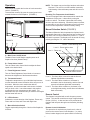
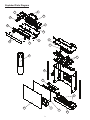
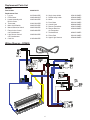
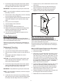
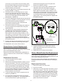
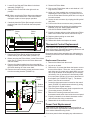
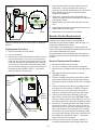
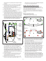
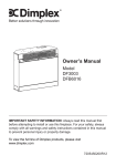
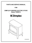
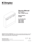
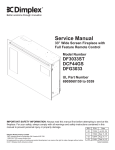
Service Manual
26” Self Trimming Fireplace with 3 Stage Remote
Model Number:
DF2690
MOD: 0
REV
00
PCN
DATE
11047 Nov 14, 08
Dimplex North America Limited
1367 Industrial Road Cambridge ON Canada N1R 7G8
1-800-668-6663 www.dimplex.com
In keeping with our policy of continuous product development, we reserve the right to make changes without notice.
7400010000rev00
Table Of Contents
Page 1 Operation
Page 3 Exploded Parts Diagram
Page 4 Parts List
Page 4
Wiring Diagram
Page 5
Front Glass Replacement
Page 5
Light Bulb Replacement
Page 6
Mirror Replacement
Page 6 Main Power On/Off Switch Replacement
Page 7 Manual Selection Switch Replacement
Page 7 Light Dimmer Replacement
Page 8 Flame Action Control Replacement
Page 8 Flicker Motor/Flicker Rod Replacement
Page 9 Thermostat Control Replacement
Page 10
Power Cord Replacement
Page 10 Remote Control Replacement
Page 11 Heater Assembly Replacement
Operation
NOTE: The heater may emit a slight, harmless odor when
first used. This odor is a normal condition caused by
initial heating of internal heater parts and will not occur
again.
This section will explain the function of each convenient
control. (FIGURE 2)
To access the controls, flip open the control panel cover
towards the bottom of the fireplace. (FIGURE 1)
Resetting The Temperature Cutoff Switch
This unit is equipped with a thermostat which controls the
temperature of the room. It does this by turning the
heater on and off. The heater is protected with a safety
device to prevent overheating. Should the heater overheat,
an automatic cut out will turn the heater off and it will come
back on when temperature reaches its safety setting.
FIGURE 1
Manual Selection Switch (FIGURE 3)
The Manual Selection Switch operates the fireplace levels
sequentially, flame only to flame and low heat, to flame and
high heat. The level is increased every time the “ I “ side of
the switch is pressed. The fireplace can be turned off at any
point by pressing the “ II ” side of the switch.
FIGURE 2
A
B
C
D
E
F
FIGURE 3
Level 3 - Flame and high heat
Level 2 - Flame and low heat
Level 1 - Flame only
A. Main Power On/Off Switch
The Main Power On/Off Switch supplies power to all
fireplace functions (Heater/Flame).
B. Flame Action Control
Turn the Flame Action Control knob to adjust the flame
speed to the desired level.
C. Flame Brightness Control
Manual Section Switch
Turn the Flame Brightness Control knob to increase or
decrease the brightness of the flame and embers.
Level 1: The flame effect is turned on and the first red
indicator light flashes momentarily.
Level 2: The flame effect remains on, the heater is
activated to the low heat setting, and the first and
second red indicator lights flash momentarily.
Level 3: The flame effect remains on, the heater is set
to the high heat setting, and all three red indicators
flash momentarily.
D. Thermostat Control
To adjust the temperature to your individual requirements,
turn the thermostat control clockwise all the way to turn on
the heater. When the room reaches the desired
temperature, turn the thermostat knob counter clockwise
until you hear a click. Leave thermostat in this position
to maintain the room temperature at this setting. For
additional heat, turn clockwise until you hear the click again
and the heater will turn on.
Remote Control
The fireplace is supplied with a radio frequency remote
control. This remote control has a range of approximately
50 feet (15.25 m). It does not have to be pointed at the
fireplace and can pass through most obstacles (including
walls).
E. LED Indicators
Indicates the current function of the fireplace: Flame only;
Flame and Low Heat; and Flame with High Heat.
F. Manual Selection Switch
Toggles sequentially through the 3 levels of the fireplace’s
functions.
Remote Control Initialization
This procedure is required every time there is a loss of
power to the remote control in the fireplace. (i.e. power
failure, breaker tripped, main power switch is turned off)
1
1.Ensure that power is supplied through main service
panel.
2.Locate manual controls. (FIGURE 1)
3.Activate main power switch.
4.Press and hold the Manual Selection Switch in the
“ I “ position for 5-10 seconds. (The second red indicator light will flash). (FIGURE 3)
5.Press the ON button located on the remote control
transmitter.
FIGURE 4
Battery
This will synchronize the remote control transmitter and
receiver.
Battery
Cover
Remote Control Usage
The remote control operates the fireplace levels
sequentially. The level is increased every time the “ON”
button on the transmitter is pressed. The fireplace can be
turned off at any point by pressing the “OFF” button on the
remote control transmitter.
Level 1: The flame effect is turned on and the first red
indicator light is activated.
Level 2: The flame effect remains on, the heater is
activated to the low heat setting, and the first and
second red indicator lights remain activated.
Level 3: The flame effect remains on, the heater is set to
the high heat setting, and all three red indicator lights
are activated.
Battery Replacement (FIGURE 4)
To replace battery:
1. Slide battery cover open on the hand held transmitter.
2. Install one 12-volt (A23) battery in the battery holder.
3. Close the battery cover.
2
Exploded Parts Diagram
11
7
18
8
2
5
16
17
4
14
6
3
15
19
9
10
11
1
13
12
3
18
Replacement Parts List
DF2690
Part Number
Replacement Part:
1. Log set
2. Flicker Motor
3. Heater Assembly with
Built-in Cutout
4. Thermostat
5. Main On/Off Switch
6. Manual Selection Switch
7. Flame Action Control
c/w Potentiometer
8. Light Dimmer Control
c/w Potentiometer
9. Cord Set
6904410159
10. Single Lamp holder
11. Double Lamp holder
12. Mirror
13. Front Glass
14. Control Knob
15. Remote Transmitter
16. Remote Receiver
c/w Transmitter
17. Terminal Block
18. Flicker Rod
19. Upper Light Harness
0437960100RP
3000240200KIT
2000330100RP
2300150100RP*
2800070700RP
2800070500RP
3000240500RP
3000250100RP
4100040200RP
Wiring Diagram - DF2690
4
2500150300RP
2500400300RP
5901210200RP
5901220100RP
8800000200RP
3000370600RP
3000430800RP
4000070100RP
5901250100RP
2500400300RP
Front Glass Replacement
Upper Bulb Requirements:
A quantity of two (2) chandelier or candelabra bulbs with an
E-12 (small) socket base, 15 watt rating are required.
CAUTION: Do Not Exceed 15 Watts Per Bulb
If unit was operating prior to servicing allow at least 10
minutes for light bulbs and heating element to cool off to
avoid accidental burning of skin.
Disconnect power before attempting any maintenance or
cleaning to reduce the risk of electric shock or damage to
persons.
FIGURE 6
Loosen
Replacement Procedure
1. 2. 3. 4. 5. 6.
Slide fireplace out of mantel.
Lay unit on it’s back for safe removal of front glass.
Remove three (3) Phillips screws from right side of trim.
Remove trim.
Slide glass to the right side of the fireplace to remove.
(FIGURE 5)
Reassemble using replacement Front Glass in reverse
order as described above.
Tighten
Removing and Replacing Bulb While
Holding Socket
Upper Bulb Replacement Procedure
1. 2. 3. 4. 5. CAUTION: Even though the glass is safety glass it may
break if bumped, struck or dropped. Care must be
taken when handling the glass.
FIGURE 5
Upper
Bulbs (x2)
Slide fireplace out of mantel.
Lay unit on it’s back for safe removal of front glass.
Remove three (3) Phillips screws from right side of trim.
Remove trim.
Slide glass to the right side of the fireplace to remove.
(FIGURE 5)
CAUTION: Even though the glass is safety glass it may
break if bumped, struck of dropped. Care must be
taken when handling the glass.
Lower
Bulbs (x3)
4.
5.
6.
7.
Trim
Log set
Front Glass
The upper bulbs are located in each corner of the
upper part of the fireplace as shown in FIGURE 5.
Remove the upper light block by removing the (four) 4
Philips mounting screws located under each of the
bulbs.
Replace bulb(s) that require replacement, holding onto
the light socket while unscrewing the bulb. (FIGURE 6)
Reassemble in the reverse order as above.
Lower Bulb Requirements:
A quantity of three (3) chandelier or candelabra bulbs with
an E-12 socket base, 60 watt rating are required.
CAUTION: Do Not Exceed 60 Watts Per Bulb
Light Bulb Replacement
If unit was operating prior to servicing allow at least 10
minutes for light bulbs and heating element to cool off to
avoid accidental burning of skin.
Disconnect power before attempting any maintenance or
cleaning to reduce the risk of electric shock or damage to
persons.
Light bulbs need to be replaced when you notice a dark
section of the flame or when the clarity and detail of the log
exterior disappears. There are two bulbs at the top of the
opening that illuminate the log set exterior and three bulbs
under the log set which generate the flames and embers.
It is a good idea to replace all of the light bulbs at one time
if they are close to the end of their rated life. Group
replacement will reduce the number of times you need to
open the unit to replace the light bulbs.
Lower Bulb Replacement Procedure
1.
2.
3.
4. Slide fireplace out of mantel.
Lay unit on it’s back for safe removal of front glass.
Remove three (3) Phillips screws from the right side of trim.
Slide glass to right side of fireplace to remove.
(FIGURE 5)
CAUTION: Even though the glass is safety glass it may
break if bumped, struck of dropped. Care must be
taken when handling the glass.
5
7.
8.
9.
5. Pull the front edge of the plastic ember bed or plastic
grate up and forward until the rear tab releases from
the ledge located at the bottom of the mirror.
IMPORTANT: Only handle the log set by the ember bed.
NOTE: Log set fits tightly into firebox, some force may be
necessary to remove.
FIGURE 7
6. Remove flicker rod by sliding flicker rod to the left away
from the flicker motor and lifting out.
7. Remove light filter bracket (the metal bracket will have
a tinted film adhered to it) for easier access to light
bulbs.
8. Set log set in front of fireplace.
9. Unscrew bulbs counter clockwise.
10. Insert new bulbs.
11. Replace light filter bracket and flicker rod.
12. Replace the log set by inserting the front edge of the
fireplace and push down on the rear edge of the
ember bed until it snaps into place.
13. Lay unit on it’s back and slide front glass back into
position and attach trim.
Mirror
Clamp
Mirror Replacement
Main On/Off Switch Replacement
If the fireplace was operating prior to servicing allow at
least 10 minutes for light bulbs and heating element to cool
off to avoid accidental burning of skin.
Disconnect power before attempting any maintenance or
cleaning to reduce the risk of electric shock or damage to
persons.
If the fireplace was operating prior to servicing allow at
least 10 minutes for light bulbs and heating element to cool
off to avoid accidental burning of skin.
Disconnect power before attempting any maintenance or
cleaning to reduce the risk of electric shock or damage to
persons.
Replacement Procedure
1.
2.
3.
4. Push the mirror up from underneath to clear the frame and remove.
Insert replacement mirror top end first and lay the bottom end gently in the bottom track of the frame.
Tighten clamps back into place and reassemble
fireplace in reverse order as described above.
Main On/Off Switch Replacement Procedure:
Slide fireplace out of mantel.
Lay unit on it’s back for safe removal of front glass.
Remove three (3) Phillips screws from the right side of trim.
Slide glass to right side of fireplace to remove.
(FIGURE 5, Page 4)
1.
2.
3.
4.
5.
6.
7.
CAUTION: Even though the glass is safety glass it may
break if bumped, struck of dropped. Care must be
taken when handling the glass.
5. Pull the front edge of the plastic ember bed or plastic
grate up and forward until the rear tab releases from
the ledge located at the bottom of the mirror.
IMPORTANT: Only handle the log set by the ember bed.
NOTE: Log set fits tightly into firebox, some force may be
necessary to remove.
6. Loosen but do not remove the two (2) Philips screws
that clamp the mirror in place, and swivel down so that
the clamp clears the edge of the mirror. (FIGURE 7)
6
Remove the firebox from the mantel.
Lay unit on its back.
Remove the 12 screws that fasten the bottom cover to
the rest of the firebox. There are: two (2) screws on
each side; two (2) screws on the back panel (you may
have to tip the bottom of the fireplace up if it is laying
on its back), four (4) screws in the front directly under
the control panel; and two (2) screws on the bottom of
the fireplace (see FIGURE 8, Page 7). The bottom
panel is now free to be removed.
Locate the Main On/Off Switch mounted on the control
panel on the left side (FIGURE 9) and disconnect
the two (2) wiring clips noting their original locations.
Depress the two (2) retainer clips on the rear of the
switch and push the switch out of the cover.
Properly orientate the new switch and re-connect all of
the wiring clips and connections as before.
Reassemble in the reverse order as above.
FIGURE 8
FIGURE 10
Screws To Remove
FIGURE 9
Manual Selection
Switch
Wire
Connectors (3)
Main ON/OFF
Switch
Retainer Clips
(one top, one bottom)
7. Reassemble in the reverse order as above.
Light Dimmer Replacement
Retainer Clips
(one top, one bottom)
If the fireplace was operating prior to servicing allow at
least 10 minutes for light bulbs and heating element to cool
off to avoid accidental burning of skin.
Disconnect power before attempting any maintenance or
cleaning to reduce the risk of electric shock or damage to
persons.
Manual Selection Switch Replacement
Replacement Procedure:
If the fireplace was operating prior to servicing allow at
least 10 minutes for light bulbs and heating element to cool
off to avoid accidental burning of skin.
Disconnect power before attempting any maintenance or
cleaning to reduce the risk of electric shock or damage to
persons.
1.
2.
3.
Replacement Procedure
1.
2.
3.
4.
5.
6.
Remove the firebox from the mantel.
Lay unit on its back.
Remove the 12 screws that fasten the bottom cover to
the rest of the firebox. There are: two (2) screws on
each side; two (2) screws on the back panel (you may
have to tip the bottom of the fireplace up if it is laying
on its back), four (4) screws in the front directly under
the control panel; and two (2) screws on the bottom of
the fireplace (see FIGURE 8). The bottom panel is now
free to be removed.
Locate the Manual Selection Switch mounted on the
control panel on the right side (FIGURE 9) and
disconnect the three (3) wiring clips noting their original
locations.
Depress the two (2) retainer clips on the rear of the
switch and push the switch out of the cover.
Properly orientate the new switch and re-connect all of
the wiring clips and connections as before.
Remove the firebox from the mantel.
Lay unit on its back.
Remove the 12 screws that fasten the bottom cover to
the rest of the firebox. There are: two (2) screws on
each side; two (2) screws on the back panel (you may
have to tip the bottom of the fireplace up if it is laying
FIGURE 11
Retaining
Nut
Potentiometer
Light Dimmer
Control Board
Mounting Studs (4)
7
on its back), four (4) screws in the front directly under
the control panel; and two (2) screws on the bottom of
the fireplace (see FIGURE 8, Page 7). The bottom
panel is now free to be removed.
4. Locate the Light Dimmer Control Board mounted on the
left side (FIGURE 11, Page 6).
5. Disconnect the two (2) wire leads from the control
board on the right hand side which connect to the
dimmer’s potentiometer, noting their original locations.
(the wire runs underneath the control board to the
potentiometer - FIGURE 11)
6. Pull off the Light Dimmer Control knob and unscrew the
retaining nut. (FIGURE 11) The potentiometer can now
be removed from the panel by pushing the
potentiometer through the front of the panel and
remove from inside the cabinet.
7. Disconnect the last two (2) remaining wire leads from
the control board on the left hand side, noting their
original locations.
8. The Light Dimmer Control board is fastened to the
underside of the ember bed support by four (4)
mounting studs, one in each corner. (FIGURE 11)
Either squeeze each stud’s clasp to release, or use
side cutters to cut and remove each of the four corner
mounting studs on the board. Clear both ends of the
cut mounting stud from the control board and the
support panel - new mounting studs are supplied with
the replacement part.
9. Properly orientate the new potentiometer and control
board and re-connect all of the wiring connections.
10. Reassemble in the reverse order as above.
potentiometer through the front of the panel and
remove from inside the cabinet.
7.
The Flame Action Control board is fastened to the
underside of the ember bed support by four (4)
mounting studs, one in each corner. (FIGURE 12)
Either squeeze each stud’s clasp to release, or use
side cutters to cut and remove each of the four corner
mounting studs on the board. Clear both ends of the
cut mounting stud from the control board and the
support panel - new mounting studs are supplied with
the replacement part.
Flame Action Control Replacement
8.
9.
FIGURE 12
Retaining
Nut
Potentiometer
Flame Action
Control Board
Mounting Studs (4)
If the fireplace was operating prior to servicing allow at
least 10 minutes for light bulbs and heating element to cool
off to avoid accidental burning of skin.
Disconnect power before attempting any maintenance or
cleaning to reduce the risk of electric shock or damage to
persons.
Flicker Motor/Flicker Rod Replacement
If the fireplace was operating prior to servicing allow at
least 10 minutes for light bulbs and heating element to cool
off to avoid accidental burning of skin.
Disconnect power before attempting any maintenance or
cleaning to reduce the risk of electric shock or damage to
persons.
Replacement Procedure:
1.
2.
3.
5.
6.
Properly orientate the new Flame Action Control
board and potentiometer and re-connect all of the wiring connections.
Reassemble in the reverse order as above.
Remove the firebox from the mantel.
Lay unit on its back.
Remove the 12 screws that fasten the bottom cover to
the rest of the firebox. There are: two (2) screws on
each side; two (2) screws on the back panel (you may
have to tip the bottom of the fireplace up if it is laying
on its back), four (4) screws in the front directly under
the control panel; and two (2) screws on the bottom of
the fireplace (see FIGURE 8, Page 7)). The bottom
panel is now free to be removed.
Locate the Flame Action Control mounted on the left
hand side. (FIGURE 12)
Pull off the Flame Action Control knob and unscrew
the retaining nut (FIGURE 12). The potentiometer can
now be removed from the panel by pushing the
Replacement Procedure:
1.
2.
3.
8
Remove the firebox from the mantel.
Lay unit on its back.
Remove the 12 screws that fasten the bottom cover to
the rest of the firebox. There are: two (2) screws on
each side; two (2) screws on the back panel (you may
have to tip the bottom of the fireplace up if it is laying
on its back), four (4) screws in the front directly under
the control panel; and two (2) screws on the bottom of
the fireplace (see FIGURE 8, Page 7). The bottom
panel is now free to be removed.
4.
5.
Locate Flicker Rod and Flicker Motor in the base
assembly. (FIGURE 13)
Gently pull the Flicker Rod to the right as far as
possible.
11. Discard old Flicker Motor.
12. Pick up new Flicker Motor and cut wire leads to 3 1/2”
long with wire cutters.
13. Using one of the supplied wire connectors from the
Replacement Part Kit, place one (1) yellow wire from
the new Flicker Motor and the yellow wire cut in step 8
into each terminal.
14. Secure the wire connector by crimping the 3M symbol
with pliers.
15. Pull on end of wires to ensure a strong connection.
16. Repeat the process for the four (4) remaining wires.
ENSURE THAT ALL WIRES ARE PAIRED BY
COLOUR IN EACH CONNECTOR.
17. Properly orientate and secure the replacement Flicker
Motor to the bracket with screws removed in step 9.
18. Replace rubber bushing on motor shaft.
19. Replace Flicker Rod.
20. Reassemble firebox and replace in mantel.
NOTE: When removing the Flicker Motor some damage
may occur to the Flicker Rod. If the Flicker Rod is
damaged, replace to insure proper operation.
6. Cautiously bend the Flicker Rod enough so that the
remaining end of the Flicker Rod clears the plastic
bushing.
FIGURE 13
Flicker
Rod
Flicker
Motor
Thermostat Control Replacement
If the fireplace was operating prior to servicing allow at
least 10 minutes for light bulbs and heating element to cool
off to avoid accidental burning of skin.
Disconnect power before attempting any maintenance or
cleaning to reduce the risk of electric shock or damage to
persons.
7. Remove the Flicker Rod by pulling it free from the
rubber bushing on the motor shaft. (FIGURE 14)
8. Before removing the Flicker Motor, cut the Flicker Motor
wires (five (5) in total) close to the Flicker Motor end
with wire cutters.
9. Remove the rubber bushing from the motor shaft by
applying needle nose pliers to the motor shaft and twist
the rubber bushing off of the motor shaft.
10. Remove the motor mounting screws and remove motor
from the mounting bracket. (FIGURE 14)
FIGURE 14
Replacement Procedure:
1.
2.
3.
5.
6.
7.
8.
9.
Mounting
Screw
Rubber
Bushing
Flicker
Motor
Mounting
Screw
Remove the firebox from the mantel.
Lay unit on its back.
Remove the 12 screws that fasten the bottom cover to
the rest of the firebox. There are: two (2) screws on
each side; two (2) screws on the back panel (you may
have to tip the bottom of the fireplace up if it is laying
on its back), four (4) screws in the front directly under
the control panel; and two (2) screws on the bottom of
the fireplace (see FIGURE 8, Page 7). The bottom
panel is now free to be removed.
Locate the thermostat control mounted on the control
panel (FIGURE 15) and disconnect the two (2) wiring
clips noting their original locations.
Pull off the thermostat control knob to expose the two
(2) mounting screws. (FIGURE 15)
Remove the mounting screws and remove the
thermostat control switch from inside the control panel.
Properly orientate the new heater thermostat control
and reconnect the wiring connections.
Reassemble in the reverse order as above.
Power Cord Replacement
If the fireplace was operating prior to servicing allow at
least 10 minutes for light bulbs and heating element to cool
off to avoid accidental burning of skin.
Disconnect power before attempting any maintenance or
9
5.
6.
7.
8.
9.
FIGURE 15
Thermostat
Screw
Locate and disconnect the two (2) power cord wire
connections: one from the bottom of the two (2)
connectors on the Main On/Off Switch; the other on the
Flame Speed Control board, noting their original
locations. (FIGURE 16)
Using pliers, squeeze the sides of the plastic wire
clamp from inside the bottom assembly area and push
it through the chassis.
Release clamp from power cord and remove power
cord.
Install replacement power cord through opening in the
chassis and secure with clamp.
Reassemble in the reverse order as above.
Remote Control Replacement
Remote Control hand held transmitters require no
replacement procedure however, a reinitialization
procedure may need to be followed. Refer to Page 1 for
the Remote Initialization Procedure.
If the fireplace was operating prior to servicing allow at
least 10 minutes for light bulbs and heating element to cool
off to avoid accidental burning of skin.
Disconnect power before attempting any maintenance or
cleaning to reduce the risk of electric shock or damage to
persons.
cleaning to reduce the risk of electric shock or damage to
persons.
Replacement Procedure:
1.
2.
3.
Remove the firebox from the mantel.
Lay unit on its back.
Remove the 12 screws that fasten the bottom cover to
the rest of the firebox. There are: two (2) screws on
each side; two (2) screws on the back panel (you may
have to tip the bottom of the fireplace up if it is laying
on its back), four (4) screws in the front directly under
the control panel; and two (2) screws on the bottom of
the fireplace (see FIGURE 8, Page 7). The bottom
panel is now free to be removed.
Receiver Replacement Procedure:
1. Remove the firebox from the mantel.
2. Lay unit on its back for safe removal of front glass.
3. Remove three (3) Phillips screws from the right side of trim.
4. Slide glass to right side of fireplace to remove.
(FIGURE 5, Page 4)
5. Pull the front edge of the plastic ember bed or plastic
grate up and forward until the rear tab releases from
the ledge located at the bottom of the mirror. (FIGURE
14)
6. Loosen but do not remove the two (2) Philips screws
that clamp the mirror in place. (FIGURE 7, Page 6)
7. Push the mirror up to clear the frame and remove storing it in a safe place away from high traffic areas.
8. Coming up from the bottom assembly, in the right,
back corner is a wire with a taped “ANTENNA” label.
The wire is held in place by a loose fitting zip tie. Roll
the label around the wire and feed it through the zip tie.
9. Remove the 12 screws that fasten the bottom cover to
the rest of the firebox. There are: two (2) screws on
each side; two (2) screws on the back panel (you may
have to tip the bottom of the fireplace up if it is laying
on its back), four (4) screws in the front directly under
the control panel; and two (2) screws on the bottom of
the fireplace (see FIGURE 8, Page 7). The bottom
panel is now free to be removed.
10. Locate the Remote Control Receiver (FIGURE 17)
mounted underneath the log set support panel and
FIGURE 16
Main
On/Off
Switch
Flame
Speed
Control
Power
Cord
Wire Clamp
10
disconnect the six (6) wiring clips noting their original
locations.
11. Disconnect the three (3) wire leads from the Manual
Selection Switch. (the wires are hard-wired to the
Remote Control Receiver) (FIGURE 17)
12. Pull the Antenna wire released in step 8 through the
bottom of the chassis.
13. Locate the three (3) LEDs from inside the bottom
assembly of the firebox. (FIGURE 17)
14. Using a flathead screwdriver, gently push on the rear
edge of the plastic bushing surrounding each LED and
push each LED out from the front of the control panel.
15. Clear any silicon that may be present and firmly grasp
the sheathed ends of the wires leading to each LED
and remove the plastic pushing from each LED. Each
LED and paired wires can be fed back through the front
control panel and into the bottom assembly area.
FIGURE 17
LEDs (3)
and continue to reconnect and reassemble the fireplace
in reverse order as described above.
Heater Assembly Replacement
If the fireplace was operating prior to servicing allow at
least 10 minutes for light bulbs and heating element to cool
off to avoid accidental burning of skin.
Disconnect power before attempting any maintenance or
cleaning to reduce the risk of electric shock or damage to
persons.
Replacement Procedure
1. Remove the firebox from the mantel.
FIGURE 18
Manual Selection Switch
Manual
Selection
Switch
Wires (3)
Trim Screws
FIGURE 19
Screws to Remove
All Hardwired Ends
Antenna
Wire
Remote
Control
Receiver
2.
3.
4.
5.
Mounting
Studs (4)
16. The Remote Control Receiver control board is fastened
to the underside of the ember bed support by four (4)
mounting studs, one in each corner. (FIGURE 17)
Either squeeze each stud’s clasp to release, or use
side cutters to cut and remove each of the four corner
mounting studs on the board. Clear both ends of the
cut mounting stud from the control board and the
support panel - new mounting studs are supplied with
the replacement part.
17. Properly orientate the replacement Remote Control
receiver and adhere to the control panel with the
supplied/existing mounting studs.
18. Once the receiver board is mounted, reconnect the
LEDs in reverse order as described in steps 14 - 15
11
Remove top trim piece by unscrewing three (3) Philips
head screws that lay behind the trim piece and along
the top edge. (FIGURE 18)
Remove the 10 screws that fasten the top cover to the
rest of the firebox. There are: (four) 4 screws at the
back of the firebox, along the top; two (2) screws on
each side and at the top of the firebox; and two (2)
screws on the top of the firebox. (FIGURE 19, Page 11)
Flip the top panel over and place upside down on the
top of the unit. You may experience some resistance as the Heater Assembly is mounted to the top panel
and may be a snug fit inside the firebox. Orientate
yourself with the placement of the Heater Assembly
and wiring as shown in FIGURE 20.
Disconnect the two (2) wire connectors on the right side of the Heater Assembly (one blue, one black), the
three (3) vertically stacked wire connectors attached to
the left side of the heating element (one yellow and two
grey), and the two (2) wire connectors on the left side
of the Heater Assembly (one grey and one black),
FIGURE 20
Top Panel
Heater Assembly
Heating Element
Terminal Block
Wires Leading to Bottom Assembly
6.
noting all of their original positions.
Turn the top panel over and while supporting the
Heater Assembly and panel in one hand, remove the
five (5) heater mounting screws, noting the center
screw is of a larger diameter. (FIGURE 21)
FIGURE 21
7.
8.
9.
Separate the Heater Assembly from the top panel.
Properly orientate the new Heater Assembly and
connect all of the wiring connections.
Reassemble in the reverse order as above.
12