1
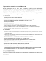
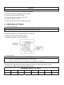
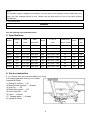
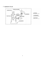
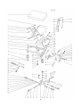
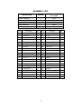
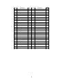
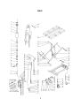
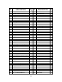
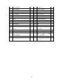
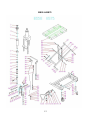
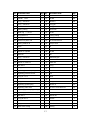
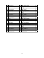
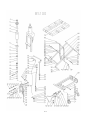
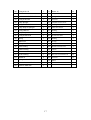
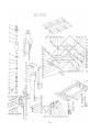
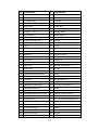
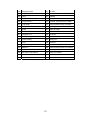
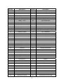
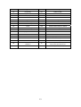
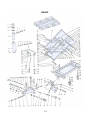
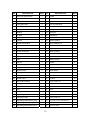
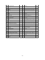
Instruction Manual
BS Series
NOTE: Owner/Operator must read and understand this instruction manual
before using the lift table.
1
Operation and Service Manual
BEFORE OPERATING THE LIFT TABLE, READ THIS MANUAL CAREFULLY AND UNDERSTAND
COMPLETELY. KEEP THIS MANUAL ON FILE FOR FUTURE REFERENCE. IF THIS IS LOST, PLEASE
CONTACT YOUR LOCAL SUPPLIER FOR A NEW COPY. ALSO, IF THE WARNING/CAUTION DECAL ON
THE UNIT IS LOST, PLEASE CONTACT YOUR LOCAL SUPPLIER FOR A NEW DECAL.
NOTE: On this manual, WARNING means the danger which can lead to death or serious injury. CAUTION
means the danger which can lead to slight injury or property damage.
1. WARNING
1.DO NOT put foot or hand in scissors mechanism.
2.DO NOT allow other person to stand in front of or behind lift table when it is moving.
3.DO NOT move lift table when table is in raised position. Load could fall down.
4.DO NOT enter under table.
5.DO NOT overload lift table.
6.DO NOT put foot in front of rolling wheels. Injury could result.
7.WATCH difference and hardness of floor level when moving lift table. Load could fall down.
8.DO NOT use lift table on slope or inclined surface, lift table may become uncontrollable and create danger.
9.DO NOT lift people. People could fall down and suffer severe injury.
2. CAUTION
1.Read this operation manual carefully and understand completely operating lift table. Improper operation
could create danger.
2.This lift table is a movable lifter designed to lift or lower rated load on table. NO NOT use lift table for other
purpose than its intended use.
3.DO NOT allow person to operate lift table who does not understand its operation.
4.DO NOT lower table too fast. Load could fall down and create danger.
5.KEEP watching the condition of load. Stop operating lift table if load becomes unstable.
6.Byake lift table when sliding load on of off table.
7.DO NOT side or end load. Load must be distributed on at least 80%of table area.
8.DO NOT use lift table with unstable, unbalanced loosely stacked load.
9.Practice maintenance work according to service instructions.
10. DO NOT modify lift table without manufacturer’s written consent.
11. REMOVE load from table and use safety stopper to prevent table from lowering when servicing lift table.
12. This lift table is not designed to be water resistant. Use lift table under dry condition.
3. DAILY INSPECTION
Daily inspection is effective to find the malfunction or fault on lift table. Check lift table on the following points
before operation.
2
CAUTION
DO NOT use lift table if any malfunction or fault is found.
(1) Check for scratch, bending or cracking on the lift table.
(2) Check if there is any oil leakage from the cylinder.
(3) Check the vertical creep of the table.
(4) Check the smooth movement of the wheel.
(5) Check the function of brake.
(6) Check if all the bolt and nuts are tightened firmly.
4. OPERATING LIFTTABLE
4-1. How to use the brake.
CAUTION
Brake lift table when not moving it in order to prevent sudden movement.
The brake is equipped with the swivel caster on the right side.
(1) Braking the wheel, press the brake pedal.
(2) Releasing the brake, lift up the brake pedal.
4-2 Lifting the table
WARNING
1. DO NOT overload lift table, stay within its rated capacity.
2. DO NOT side end load must be distributed on at least 80% of table area.
Press the lifting pedal several times the until the table reaches the desired position.
The table does not elevate after reaching the highest position even if the lifting pedal is pressed.
The table lowers slightly after reaching the highest position.
MAXIMUM CAPACITY OF TABLE
BS15
BS25
BS50
BS75
BS100
BS30D
BS50D
BS80D
150KG
250KG
500KG
750KG
1000KG
300KG
500KG
800KG
3
NOTE:
The hydraulic cylinder is designed to hold table. As is the nature of the hydraulic system, table lowers very
slowly over and extended period of time, Please note the table does not stay at the same position
ionindefiinitely.
4-3. Lowering table
WARNING
DO NOT put foot or hand in scissors mechanism.
Pull the lowering down and table lowers.
5. Specifications
Stroke
L×W×H
(mm)
Pedal to top.
(approx. times)
Wheel
(mm)
φ
Weight
(kg)
225-760
535
1000×450×950
16
100
41
830×500
335-915
580
1100×500×1010
25
125
78
500
1010×520
430-1000
570
1130×520×1185
44
150
118
BS75
750
1010×520
432-1000
568
1130×520×1260
55
150
120
BS100
1000
1010×520
440-960
520
1130×520×1260
68
150
137
BS30D
300
1010×520
435-1585
1150
1130×520×1260
53
150
150
BS50D
500
1010×520
435-1585
1150
1130×520×1260
68
150
168
BS80D
800
1010×520
490-1400
910
1130×520×1275
95
150
165
Model
Capacity
(kg)
Table
(mm)
Table
Height(mm)
BS15
150
700×450
BS25
250
BS50
6. Service instruction
6.1-1. Lubricate each point described below every month:
6.2.Change hydraulic oil every 12 months.
Lubricating Points
(1) Fitting of cylinder……Oil
(2) Roller friction surface……Grease
(3) Link Pin ……Oil
(4) Pedal fitting point……Oil
(5) Link center pin……Oil
(6) Joint……Grease
(7) Grease nipple……Grease
(8) Hydraulic circuit
4
7. Hydraulic Circuit
5
6
ASSEMBLY LIST
Quantity
PARTS ILLUST BEING
INCLUDED
Cylinder Assembly
1
13-21
Pump Unit Assembly
1
64-78
Pump Unit Sub Assembly
1
22-58
Handle Assembly
1
84-91
Pedal Assembly
1
76-77
DESCRIPTION
PARTS LIST
Item
Description
Qty.
Item
Description
Qty.
1.
Table pair
1
22.
Flow control joint
1
2.
Guide roller
4
23.
O ring
1
3.
Scissors
1
24.
Adjust casing
1
4.
Snap ring
6
25.
Spring seat
1
5.
Link pin
4
26.
Valve spring
1
6.
Safety pin
1
27.
Conical valve
1
7.
Hex bolt
16
28.
Valve seat
1
8.
Washer
18
29.
O ring
1
9.
Frame pair
1
30.
Busing
1
10.
Front wheel
2
31.
Dust seal
1
11.
Spring washer
19
32.
Y ring
1
12.
Hex. nut
18
33.
Plunger
1
13.
Piston rod
1
34.
Pump spring B
1
14.
Dust seal
1
35.
Pump spring A
1
15.
O ring
2
36.
Pump bass
1
16.
Back up ring
1
37.
Net
1
17.
Cylinder pair
1
38.
Washer
1
18.
Spring seat
1
39.
Back valve spring
1
19.
Spring
1
40.
O-ring
1
20.
Seal ring
1
41.
Plug
1
21.
Joint
1
42.
O ring
1
7
Item
Description
Qty.
Item
Description
Qty.
43.
Steering bush
1
67.
Pressure roller pin
1
44.
O ring
1
68.
Pedal Pivot Pin
1
45.
Discharge lever
1
69.
Hex. bolt
2
46.
Valve arm
1
70.
Elbow
2
47.
Socket head screw
1
71.
Oil return hose
1
48.
Spring washer
1
72.
Rubber bushing
1
49.
Washer
1
73.
High pressure hose
1
50.
Bushing
1
74.
Seal ring
6
51.
Steel ball
1
75.
Adaptor
2
52.
Steel ball holder
1
76.
Pedal Pair
1
53.
Relief spring
1
77.
Pedal rubber
2
54.
Regulating pressure plug
1
78.
Hex bolt
1
55.
O ring
1
79.
Lock bar
1
56.
Relief plug
1
80.
Hex. bolt
1
57.
O ring
1
81.
Cylinder pivot pin
1
58.
Plug
1
82.
Grease fitting
2
59.
Rear wheel
2
83.
Piston head pin
1
60.
Handle pin
4
84.
Roller chain
1
61.
Handle lock spring L
1
85.
Valve rod Ⅱ
1
61A. Handle lock spring R
1
86.
Nut M6
1
62.
Bushing
2
87.
Handle pair
1
63.
Snap ring
4
88.
Valve rodⅠ
1
64.
Pedal holder
1
89.
Control link
1
65.
Snap ring
2
90
Roll pin
1
66.
Pressure roller
1
91.
Roll pin
1
8
BS25
9
NO.
DESCRIPTION
1.
Seal cover
2.
d30×D42×7
Qty NO.
DESCRIPTION
Qty
1
56. Hex soch screw M6×16
1
Cylinder cover
1
57. Tube for steel wire
1
3.
O-ring d63×2.65
2
58. Steel wire
1
4.
O-ring d30×3.55
1
59. Nut M8
24
5.
Piston rod
1
60. Washer 8
36
6.
Spacing casing
1
61. Spring pin
1
7.
Guide ringδ1.5×15
1
62. Spring pin
1
8.
O-ring D20×2.4
1
63. Control link
1
9.
Seal ring d34×D40×4.5
1
64. Handle
1
10.
Piston rod retainer
1
65. Spacing casing
2
11.
Retaining ring
6
66. Spring washer 12
2
12.
Piston
1
67. Hexagon head stud M12×40
2
13.
Cylinder
1
68. Split pin
1
14.
Cylinder washer
1
69. Pin
1
15.
Reservior
1
70. U-fork
1
16.
O-ring d10×2.65
1
71. Nut M6
1
17.
Filler screw
1
72. Bolt
1
18.
Washer for reservior
1
73. Pedal bent pipe
1
19.
Steel ball 5
1
74. Pedal rubber
1
20.
Spring base
1
75. Shake link
1
21.
Regulating pressure spring
1
76. Spring washer 8
17
22.
Regulating pressure screw
1
77. Hex soch screw
1
23.
O-ring d7.1×1.8
1
78. Buffer mat
1
24.
End cover
1
79. Partition set
1
25.
O-ring d15×2.65
2
80. Pin axle
1
26.
Regulating speed spring
1
81. Retainer 10
2
27.
Regulating speed slide valve
1
82. Pin axle
1
28.
Regulating speed spring casing
1
83. Retainer 20
1
29.
Regulating speed valve casing
1
84. Washer
1
30.
Steel ball 7
1
85. Pin axle
1
31.
O-ring d6.9×1.8
1
86. Link
2
32.
Conical valve
1
87. Hex soch screw M8×20
16
33.
Check valve spring
1
88. Wheel
2
34.
Check valve casing
1
89. Wheel
2
35.
O-ring d10×1.8
1
90. Chassis
1
36.
Check valve screw
1
91. Pin axle
4
37.
Spring base
1
92. Hex screw M6×12
4
38.
Spring
1
93. Bushing
4
39.
Seal cover d18×D25×4.5
1
94. Scissors lever
1
10
40.
O-ring d18×2.65
1
95. Retainer 16
5
41.
Pump plunger
1
96. Roller for chassis
2
42.
Y-ring
1
97. Bushing
4
43.
Pump body for plunger
1
98. Nut M10
2
44.
O-ring d28×3.1
1
99. Spring washer 10
4
45.
Pump body
1
100. Washer 10
8
46.
O-ring d10.6×2.65
1
101. Safety rod
2
47.
Spring
1
102. Screw bolt M10×40
2
48.
Reflux rod
1
103. Spring pin 8×40
2
49.
O-ring d4×1.8
1
104. Roller for table
2
50.
Guide casing
1
105. table
1
51.
Protect casing
1
106. Pin axle
1
52.
Lever
1
1 ~
A
Pump ass'y
51
53.
Lever bushing
1
B
Swivel wheel ass'y
89
54.
Washer 6
2
C
Front wheel ass'y
88
55.
Spring washer 6
5
Seal
D
kit
ass'y
1,3,4,7,8,9,16,23,
25,31,35,39,40,42,44,46,49
Handle ass'y
E
11
64,68~72
54,57 ~
BS50 & BS75
12
NO. DESCRIPTION
1. Seal cover
Qty NO. DESCRIPTION
Qty
1
56. Steel wire
1
2. Cylinder cover
1
57. Nut M8
24
3. O-ring d63×2.65
2
58. Washer 8
38
4. O-ring d30×3.55
1
59. Spring pin
1
5. Piston Rod
1
60. Spring pin
1
6. Spacing casing
1
61. Control link
1
7. Guide ring δ1.5×15
1
62. Handle
1
8. O-ring D20×2.4
1
63. Spacing casing
2
9. Seal ring d34×D40×4.5
1
64. Spring washer 12
2
10. Retainer for piston rod
1
65. Hex screw M12×40
2
11. Spacing retainer 18
6
66. Split pin 2×15
1
12. Piston
1
67. Pin
1
13. Cylinder
1
68. U- fork
1
14. Washer for cylinder
1
69. Nut M6
1
15. Reservior
1
70. Bolt
1
16. O-ring d10×2.65
1
71. Pedal bent pipe
1
17. Filler screw
1
72. Hex soch screw M8×20
2
18. Washer for reservior
1
73. Shake link
1
19. Steel ball 5
1
74. Spring
2
20. Spring base
1
75. Retainer 10
2
21. Regulating pressure spring
1
76. Pin axle
2
22. Regulating pressure screw
1
77. Link
2
23. O-ring d7.1×1.8
1
78. Wheel
2
24. End cover
1
79. Nut M10
16
25. O-ring d15×2.65
2
80. Spring washer 10
16
26. Regulating speed spring
1
81. Washer 10
36
27. Regulating slide-valve
1
82. Hex soch screw M10×25
16
28. Regulating speed spring casing
1
83. Wheel
2
29. Regulating speed slide-casing
1
84. axle
1
30. Steel ball 7
1
85. Retainer 20
4
31. O-ring d6.9×1.8
1
86. Chassis
1
32. Conical valve
1
87. Table
1
33. Spring
1
88. Roller for table
2
34. Check valve casing
1
89. Bushing
2
d30×D42×7
13
35. O-ring d10×1.8
1
90. Split pin 3.2×26
2
36. Check valve screw
1
91. Nut M16
1
37. Seal cover d18×D25×4.5
1
92. Washing
1
38. O-ring d18×2.65
1
93. Bushing
2
39. Pump plunger
1
94. Spring pin 8×40
2
40. Y-ring
1
95. Screw bolt M10×40
2
41. Pump body for plunger
1
96. Safety rod
2
42. O-ring D28×3.1
1
97. Nut M10
2
43. Pump body
1
98. External scissors lever
1
44. O-ring d10.6×2.65
1
99. Bushing
2
45. Spring
1
100. Roller for chassis
2
46. Reflux rod
1
101. Internal scissors lever
1
47. O-ring d4×1.8
1
102. Pin axle for chassis
1
48. Guide casing
1
103. Spring washer 8
2
49. Protect casing
1
104. Hex screw M8×16
2
50. Lever
1
105. Pin axle for scissons
1
51. Lever bushing
1
106. Pin axle for table
1
52. Washer 6
2
107. Bushing
2
53. Spring washer 6
5
108. Bolt M8×12
1
54. Hex soch screw M6×16
1
109. Oil cup
2
55. Tube for steel wire
1
110. Screw M6
1
14
15
NO. DESCRIPTION
1.
Seal cover
2.
Qty's
NO. DESCRIPTION
Qty's
1
57. Steel wire
1
Cylinder cover
1
58. Nut M8
24
3.
O-ring d75×3.55
1
59. Washer 8
38
4.
O-ring d35.5×3.55
1
60. Spring pin
1
5.
Piston Rod
5
61. Spring pin
1
6.
Spacing casing
1
62. Control link
1
7.
Guiding δ2×15
1
63. Handle
1
8.
O-ring D20×2.4
1
64. Spacing casing
2
9.
Seal ring d39×D45×4.5
1
65. Spring washer 12
2
10. Retainer for piston rod
1
66. Hex screw M12×40
2
11.
6
67. Split pin 2×15
1
12. Piston
1
68. Pin
1
13. Cylinder
1
69. U- fork
1
14. Washer for cylinder
1
70. Nut M6
1
15. Reservior
1
71. Bolt
1
16. O-ring d10×2.65
1
72. Pedal bent pipe
1
17. Filler screw
1
73. Hex screw M8×20
2
18. O-ring d75×2.65
1
74. Shake link
1
19. Washer for reservior
1
75. Spring
2
20. Steel ball 5
1
76. Pin axle
2
21. Spring base
1
77. Retainer 10
2
22. Regulating pressure spring
1
78. Link
2
23. Regulating pressure screw
1
79. Table
1
24. O-ring d7.1×1.8
1
80. Retainer 20
4
25. End cover
1
81. Roller for table
2
26. O-ring d15×2.65
2
82. Bushing
2
27. Regulating speed spring
1
83. Split pin 3.2×26
2
28. Regulating slide-valve
1
84. Nut M16
2
29. Regulating speed spring casing
1
85. Washing
2
30. Regulating speed slide-casing
1
86. Bushing
2
31. Steel ball 7
1
87. Pin axle for scissors
2
32. O-ring d6.9×1.8
1
88. Spring washer 8
3
33. Conical valve
1
89. Hex screw M8×10
3
34. Spring
1
90. Spring pin 8×40
2
35. Check valve casing
1
91. Screw bolt M10×40
2
d35×D43.5×5
Spacing retainer 18
16
36. O-ring d10×1.8
1
92. Washer 10
34
37. Check valve screw
1
93. Safety rod
2
38. Seal cover d18×D25×4.5
1
94. Spring washer 10
34
39. O-ring d18×2.65
1
95. Nut M10
2
40. Pump plunger
1
96. External scissors lever
1
41. Y-ring d10×D18×6
1
97. Bushing
2
42. Pump body for plunger
1
98. Roller for chassis
2
43. O-ring D28×3.1
1
99. Bushing
2
44. Pump body
1
100. Pin axle for chassis
1
45. O-ring d10.6×2.65
1
101. Pin axle for table
1
46. Spring
1
102. Bushing
2
47. Reflux rod
1
103. Oil cup
2
48. O-ring d4×1.8
1
104. Bolt M8×12
1
49. Guide casing
1
105. Internal scissors lever
1
50. Protect casing
1
106. Chassis
1
51. Lever
1
107. axle
1
52. Lever bushing
1
108. Hex soch screw M10×25
16
53. Washer 6
2
109. Nut M10
16
54. Spring washer 6
5
110. Wheel
2
55. Hex soch screw M6×16
1
111. Wheel
2
56. Tube for steel wire
1
17
18
NO.
DESCRIPTION
NO.
DESCRIPTION
1.
Seal cover
2.
Cylinder cover
58. Washer 8
3.
O-ring d63×2.65
59. Spring pin
4.
O-ring d30×3.55
60. Spring pin
5.
Piston Rod
61. Control link
6.
Spacing casing
62. Handle
7.
Guiding δ1.5×15
63. Spacing casing
8.
O-ring D20×2.4
64. Spring washer 12
9.
Seal ring d34×D40×4.5
65. Hex screw M12×40
d30×D42×7
57. Nut M8
10. Retainer for piston rod
66. Spcit pin
11. Spacing retainer 18
67. Pin
12. Piston
68. U- fork
13. Cylinder
69. Nut M6
14. Washer for cylinder
70. Bolt
15. Reservior
71. Pedal bent pipe
16. O-ring
72. Hex headed bolt
d10×2.65
17. Filler screw
73. Shake link
18. Washer for reservior
74. Spring
19. Steel ball 5
75. Retainer ring for axle 10
20. Spring base
76. Pin axle
21. Regulating pressure spring
77. Link
22. Regulating pressure screw
78. Wheel
23. O-ring d7.1×1.8
79. Nut M10
24. End cover
80. Spring washer 10
25. O-ring d15×2.65
81. Washer 10
26. Regulating speed spring
82. Hex soch screw M10×25
27. Regulating slide-valve
83. Wheel
28. Regulating speed spring casing
84.
29. Regulating speed slide-casing
85. Retaining ring for axle 20
30. Steel ball 7
86. Chassis
31. O-ring d6.9×1.8
87. Hex
32. Conical valve
88. Pin axle
33. Spring
89. Bushing
34. Check valve casing
90. Washer
35. O-ring d10×1.8
91. Slotting nut M16×1.5
36. Check valve screw
92. Split pin
37. Seal cover d18×D25×4.5
93. Pin axle
19
Pin axle
socket screw Bolt M8×16
38. O-ring d18×2.65
94. Pin axle
39. Pump plunger
95. Hex socket set screw M8×12
40. Y-ring
96. Bushing
41. Pump body for plunger
97. Oil cup
42. O-ring D28×3.1
98. External scissors lever for table
43. Pump body
99. Internal scissors lever for table
44. O-ring d10.6×2.65
100. Bushing
45. Spring
101. Roller for table
46. Reflux rod
102. Table
47. O-ring d4×1.8
103. Pin 8×40
48. Guide casing
104. Hex headed screw bolt M10×40
49. Protect casing
105. Safety rod
50. Lever
106. Nut M10
51. Lever bushing
107. External scissors lever for chassis
52. Washer 6
108. Internal scissors lever for chassis
53. Spring washer 6
109. Bushing
54. Hex soch screw M6×16
110. Roller for chassis
55. Tube for steel
111. Pin axle
56. Steel wire
20
BS 50D
21
Item No.
1
Description
Seal cover
d35×D43.5×5
Item No.
Description
59
Spring pin
2
Cylinder cover
60
Spring pin
3
O-ring d75×3.55
61
Control link
4
O-ring d35.5×3.55
62
Handle
5
Piston Rod
63
Spacing casing
6
Spacing casing
64
Spring washer 12
7
Guiding δ2×15
65
Hex screw M12×40
8
O-ring D20×2.4
66
Spcit pin
9
Seal ring d39×D40×4.5
67
Pin
10
Retainer for piston rod
68
U- fork
11
Spacing retainer 18
69
Nut M6
12
Piston
70
Bolt
13
Cylinder
71
Pedal bent pipe
14
Washer for cylinder
72
Hex headed bolt
15
Reservior
73
Shake link
16
O-ring d10×2.65
74
Spring
17
Filler screw
75
Retainer ring for axle 10
18
Washer for reservior
76
Pin axle
19
Steel ball 5
77
Link
20
Spring base
78
Wheel
21
Regulating pressure spring
79
Nut M10
22
Regulating pressure screw
80
Spring washer 10
23
O-ring d7.1×1.8
81
Washer 10
24
End cover
82
Hex soch screw M10×25
25
O-ring d15×2.65
83
Wheel
26
Regulating speed spring
84
Pin axle
27
Regulating slide-valve
85
Retaining ring for axle 20
28
Regulating speed spring casing
86
Chassis
29
Regulating speed slide-casing
87
Hex socket screw Bolt M8×16
30
Steel ball 7
88
Pin axle
31
O-ring d6.9×1.8
89
Bushing
32
Conical valve
90
Washer
33
Spring
91
Slotting nut M16×1.5
34
Check valve casing
92
Split pin
35
O-ring d10×1.8
93
Pin axle
36
Check valve screw
94
Pin axle
37
Seal cover d18×D25×4.5
95
Hex socket set screw M8×12
38
O-ring d18×2.65
96
Bushing
39
Pump plunger
97
Oil cup
40
Y-ring
98
External scissors lever for table
41
Pump body for plunger
99
Internal scissors lever for table
22
42
O-ring D28×3.1
100
Bushing
43
Pump body
101
Roller for table
44
O-ring d10.6×2.65
102
Table
45
Spring
103
Pin 8×40
46
Reflux rod
104
Hex headed screw bolt M10×40
47
O-ring d4×1.8
105
Safety rod
48
Guide casing
106
Nut M10
49
Protect casing
107
External scissors lever for chassis
50
Lever
108
Internal scissors lever for chassis
51
Lever bushing
109
Bushing
52
Washer 6
110
Roller for chassis
53
Spring washer 6
111
Pin axle
54
Hex soch screw M6×16
112
Bolt M6×8
55
Tube for steel
A
56
Steel wire
B
Swivel wheel ass'y
83
57
Nut M8
C
Front wheel ass'y
78
58
Washer 8
D
E
23
Pump ass'y
Seal kit ass'y
1~49
1,3,4,7,8,9,16,23,
25,31,35,37,38,,40,42,44,47
Handle ass'y
52,55~62,66~70
BS80D
24
NO.
DESCRIPTION
Qty's NO.
DESCRIPTION
Qty's
1. Seal cover d50×D58×5
1
59. Nut M8
6
2. Y-ring d50×D58×8.2
1
60. Washer 8
5
3. Cylinder cover
1
61. Spring
1
4. O-ring d56×2.65
1
62. Tube for steel wire
1
5. Piston Rod
1
63. Steel wire
1
6. Bushing
2
64. Spring pin
1
7. Bushing
1
65. Spring pin
1
8. Pin axle
1
66. Control link
1
9. Snap Ring 50
1
67. Handle
1
10. Cylinder
1
68. Spacing casing
2
11. Prevent burst valve
1
69. Spring washing 12
2
12. Spring
1
70. Hex screw M12×40
2
13. Seal ring 18
1
71. Snap ring
2
14. Prevent burst joint
1
72. Spacing casing
1
15. Seal ring 14
4
73. Pressure roller
1
16. High pressure Hose
1
74. Pressure roller pin
1
17. Joint
2
75. Pedal pivot pin
1
18. Split pin
1
76. Nut M6
2
19. Adjust casing seat
1
77. Spring washer 6
2
20. O-ring d18×2.4
1
78. Hex socket screw bolt M6×50
2
21. Adjust casing
1
79. Pedal rubber
1
22. Spring seat
1
80. Pedal holder
1
23. Spring
1
81. Wheel
2
24. Conical valve
1
82. Nut M10
16
25. Check valve casing
1
83. Spring washer 10
16
26. O-ring d6.9×1.8
1
84. Washer 10
32
27. Steel ball
2
85. Hex socket screw M10
16
28. Plug
1
86. Wheel
2
29. O-ring d10×2.65
2
87. Chassis
1
30. Regulating speed valve casing
1
88. Bolt M6×8
1
31. O-ring d15×2.65
2
89. Spring washer 8
1
32. Regulating speed spring seat
1
90. Hex socket screw bolt M8×16
1
33. Regulating speed spring
1
91. Table
1
34. Regulating speed slide-valve
1
92. Roller for table
2
25
35. O-ring d20×2.65
1
93. Bushing
2
36. Y-ring d20×D28×5
1
94. Retaining ring for axle 20
6
37. Pump plunger
1
95. Internal scissors lever for table
1
38. Spring
1
96. External scissors lever for table
1
39. Spring
1
97. Pin axle
3
40. Pump body
1
98. Washer
5
41. Mesh
1
99. Split Pin
5
42. Washer D5
1
100. Slotting nut M16×1.5
5
43. Discharge spring
2
101. Internal scissors lever for chassis
1
44. O-ring d14×2.4
1
102. Pin 8×40
2
45. Plug
1
103. Hex headed screw bolt
46. Discharge lever
1
104. Safety rod
2
47. O-ring d4×1.8
1
105. Nut M10
2
48. Discharge lever bushing
1
106. External scissors lever for chassis
1
49. O-ring d10.6×2.65
1
107. Bushing
10
50. Hex socket screw bolt M6×16
1
108. Bushing
2
51. Bushing
1
109. Roller for chassis
2
52. Discharge lever
1
110. Pin axle
2
53. Steel ball
1
111. Pin axle
1
54. Spring seat assembly
1
112. Pin axle
1
55. Regulating pressure spring
1
113. Hex socket set screw
56. Regulating pressure nut
1
114. Oil cup
3
57. O-ring d8×1.8
1
115. Bushing
2
58 Screw
1
26
M8×40
M8×12
2
2