1
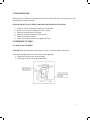
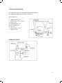
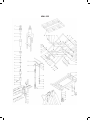
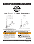
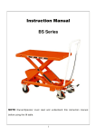
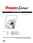
Maxx-Mini Lift
MML-50D
Service Manual
LIFT PRODUCTS INC
PO BOX 349
ELM GROVE WI 53122
262-521-5720 FAX 262-521-5725
Toll Free 877-543-8776
Model: MML-50D
S/N ________________________________
Customer____________________________
REGISTRATION INFORMATION
(To validate your warranty and receive updated service bulletins, please complete this form)
Date_______________
Model No.________________
How did you first hear of Lift Products?
____Magazine Ad (Specify which magazine)_____________________________________
____Recommended by a dealer (Name of Dealer)_________________________________
____Received information in the mail
____Internet
____Other (Please specify)___________________________________________________
What factors caused you to choose Lift Products?____________________________________
____________________________________________________________________________
____________________________________________________________________________
Describe how and where products are being used?____________________________________
____________________________________________________________________________
____________________________________________________________________________
Name of person completing this form______________________________________________
Title________________________________________________________________________
Company____________________________________________________________________
Street Address________________________________________________________________
City, State, Zip________________________________________________________________
Phone________________________ Fax No.________________________________________
Purchased From:
Name of Dealer_______________________________________________________________
Street Address________________________________________________________________
City, State, Zip________________________________________________________________
Phone No._____________________Fax No.________________________________________
Please fax this form to 262-521-5725.
OPERATION AND SERVICE MANUAL
BEFORE OPERATING THE LIFT TABLE, READ THIS MANUAL CAREFULLY AND UNDERSTAND
COMPLETELY. KEEP THIS MANUAL ON FILE FOR FUTURE REFERENCE. IF THIS IS LOST, PLEASE
CONTACT YOUR LOCAL SUPPLIER FOR A NEW COPY. ALSO, IF THE WARNING/CAUTION DECAL ON
THE UNIT IS LOST, PLEASE CONTACT YOUR LOCAL SUPPLIER FOR A NEW DECAL.
NOTE: On this manual, WARNING means the danger which can lead to death or serious injury.
CAUTION mean the danger can lead to slight or property damage.
1. WARNING
1.
2.
3.
4.
5.
6.
7.
8.
DO NOT put foot or hand in scissor mechanism.
DO NOT allow other person to stand in front of or behind lift table when it is moving.
DO NOT move lift table when table is in raised position. Load could fall down.
DO NOT enter under table.
DO NOT overload lift table.
DO NOT put foot in front of rolling wheels. Injury could result.
WATCH difference of floor level when moving lift table. Load could fall down.
DO NOT use lift table on slope or inclined surface, lift table may become uncontrollable
and create danger.
9. DO NOT lift people. People could fall down and suffer severe injury.
2. CAUTION
1. Read this operation manual carefully and understand completely operating lift table. Improper operation could create danger.
2. This lift table is a movable lifter designed to lift or lower rated load on table. DO NOT use
lift table for other purpose than its intended use.
3. DO NOT allow person to operate lift table who does not understand its operation/
4. DO NOT lower table too fast. Load could fall down and create danger.
5. KEEP watching the condition of load. Stop operating lift table if load becomes unstable.
6. Brake lift table when sliding load on or off table.
7. DO NOT side or end load. Load must be distributed on a least 80% of table area.
8. DO NOT use lift table with unstable, unbalanced loosely stacked load.
9. Practice maintenance work according to service instructions.
10.DO NOT modify lift table without manufacturer’s written consent.
11.REMOVE load from table and use safety stopper to prevent table from lowering when
servicing lift table.
12.This lift table is not designed to be water resistant. Use lift table under dry conditions.
1
3. DAILY INSPECTION
Daily inspection is effective to find the malfunction or fault on lift table. Check lift table on the
following points before operation.
CAUTION: DO NOT USE LIFT TABLE IF ANY MALFUNCTION OR FAULT IS FOUND
1.
2.
3.
4.
5.
6.
Check for scratch, bending or cracking on the lift table.
Check if there is any oil leakage from the cylinder.
Check the vertical creep of the table.
Check the smooth movement of the wheels.
Check the function of brake.
Check if all the bolts and nuts are tightened firmly.
4. OPERATING LIFT TABLE
4-1. HOW TO USE THE BRAKE
CAUTION: Brake lift table when not moving it in order to prevent sudden movement.
The brake is equipped with the swivel caster on the right side.
1. Braking the wheel, press the brake pedal.
2. Releasing the brake, lift up the brake pedal.
2
4-2. LIFTING THE TABLE
WARNING: DO NOT overload lift table. Stay within its rated capacity. DO NOT side or end load
must be distributed on at least 80% of table area.
Press the lifting pedal several times until the table reaches the desired position.
1. The table does not elevate after reaching the highest position even if the lifting pedal is
pressed.
2. The table lowers slightly after reaching the highest position.
MAXIMUM CAPACITY OF TABLE
MML-15 MML-25 MML-50 MML-75 MML-100 MML-100XL MML-30D
330 lbs 550 lbs 1,100 lbs 1,650 lbs 2,200 lbs
2,000 lbs
660 lbs
MML-50D
1,100 lbs
NOTE: They hydraulic cylinder is designed to hold table. As is the nature of the hydraulic system,
table lowers very slowly over and extended period of time. Please not the table does not stay in
the same position indefinitely.
5-3. LOWERING TABLE
WARNING: DO NOT put foot or hand in scissor mechanism.
Pull the lowering lever up and table lowers.
5. SPECIFICATIONS
Model
MML-15
MML-25
MML-50
MML-75
MML-100
MML-100XL
MML-30D
MML-50D
Capacity
(Lbs)
330
550
1100
1650
2200
2000
660
1100
Table Size
Table Height
Weight
17.75 x 27.5
19.75 x 32.75
20.5 x 39.75
20.5 x 39.75
20.5 x 39.75
31.5 x 47.25
20.5 x 39.75
20.5 x 39.75
10”-30”
12”-36”
17”-36”
17”-39”
17”-39”
17”-48”
17”-62”
17”-62”
90
172
260
264
301
358
330
370
Pedal to top.
(approx. times)
16
25
44
55
68
53
68
95
3
6. SERVICE INSTRUCTIONS
6-1. LUBRICATE EACH POINT DESCRIBED BELOW EVERY MONTH:
6-2. CHANGING HYDRAULIC OIL EVERY 12 MONTHS.
Lubricating Points:
1.
2.
3.
4.
5.
6.
7.
8.
Fitting of cylinder...Oil
Roller friction surface...Grease
Link Pin...Oil
Pedal fitting point...Oil
Link center pin...Oil
Joint...Oil
Grease nipple...Grease
Hydraulic circuit
HYDRAULIC CIRCUIT
4
MML-50D
5
PARTS LIST
ILL.
NO.
DESCRIPTION
QTY
REQ.
ILL.
NO.
DESCRIPTION
QTY
REQ.
1
Seal Cover d35xD43.5x5
1
60
Spring Pin
1
2
Cylinder Cover
1
61
Control Link
1
3
O-Ring d75x3.55
1
62
Handle
1
3a
O-Ring d75x2.65
1
63
Spacing Casing
2
4
O-Ring d35.5x3.55
1
64
Spring Washer 12
2
5
Piston Rod
1
65
Hex Screw M12x30
2
6
Spacing Casing
1
66
Split Pin 2x15
1
7
Guide Ring 2x15
1
67
Pin
1
8
O-Ring D20x2.4
1
71
Pedal Bent Pipe
1
9
Seal Ring d39xD45x4.5
1
72
Hex Soch Screw M8x20
2
10
Retainer for Piston Rod
1
73
Shake Link
1
11
Spacing Retainer 18
1
74
Spring
2
12
Piston
1
75
Retainer 10
2
13
Cylinder
1
76
Pin Axle
2
14
Cylinder Washer
1
77
Link
2
15
Reservoir
1
78
Wheel
2
16
O-Ring d10x2.65
1
79
Nut M10
16
17
Filler Screw
1
80
Spring Washer 10
16
18
Washer for Reservoir
1
81
Washer 10
36
19
Steel Ball 5
1
82
Hex Soch Screw M10x25
16
20
Spring Base
1
83
Wheel
2
21
Regulating Pressure Spring
1
84
Axle
1
22
Regulating Pressure Screw
1
85
Retainer 20
7
23
O-Ring d7.1x1.8
1
86
Chassis
1
24
End Cover
1
87
Hex Screw M8x16
5
25
O-Ring d15x2.65
2
88
Pin Axle For Chassis
1
26
Regulating Speed Spring
1
89
Bushing
8
27
Regulating Slide Valve
1
89A
Bushing
2
28
Regulating Speed Spring Casing
1
90
Washing
3
29
Regulating Speed Slide Casing
1
90A
Washing
2
30
Steel Ball 7
1
91
Slotting Nut M16x1.5
5
31
O-Ring d6.9x18
1
92
Split Pin 3.2x26
5
32
Conical Valve
1
93
Pin Axle
3
33
Spring
1
94
Pin Axle for Table
1
34
Check Valve Casing
1
95
Hex Socket Set Screw M8x12
1
35
O-Ring d10x1.8
1
96
Bushing
2
36
Check Valve Screw
1
97
Oil Cup
4
37
Seal Cover d18xD25x4.5
1
98
External Scissors Lever for Table
1
38
O-ring d18x2.65
1
99
Internal Scissors Lever for Table
1
39
Pump Plunger
1
100
Bushing
2
40
Y-Ring d10xD18x16
1
Roller for Table
2
101
6
ILL.
NO.
DESCRIPTION
QTY
REQ.
ILL.
NO.
DESCRIPTION
QTY
REQ.
41
Pump Body for Plunger
1
102
Table
1
42
O-Ring D28x3.1
1
103
Spring Pin 8x30
2
43
Pump Body
1
104
Screw Bolt M10x40
2
44
O-Ring d10.6x2.65
1
105
Safety Rod
2
45
Spring
1
106
Nut M10
2
46
Reflux Rod
1
107
External Scissors Lever for Chassis
1
47
O-Ring d4x1.8
1
108
Internal Scissors Lever for Chassis
1
48
Guide Casing
1
109
Bushing
2
49
Protect Casing
1
110
Roller for Chassis
2
50
Lever
1
111
Pin Axle
2
51
Lever Bushing
2
112
Bolt M6x8
1
52
Washer 6
2
113
Rod
1
53
Spring Washer 6
1
114
Rod
1
55
Put Pressure Assembly
2
115
Screw M6x30
1
58
Washer 8
2
116
Cover-Type Nut M6
1
A
Pump Assembly
1-49, 113, 114
B
Swivel Wheel Assembly
78
C
Front Wheel Assembly
83
D
Seal Kit Assembly
1, 3, 3A, 4, 7, 8, 9, 16, 23, 25, 31, 35, 37, 38, 40 42, 44, 47
E
Handle Assembly
52, 53, 55, 60, 61, 62, 66, 67, 115, 116
7