1
/ Battery Charging Systems / Welding Technology / Solar Electronics
42,0410,0828
009-16092015
Operating Instructions
EN
FRONIUS IG
15 / 20 / 30 / 40 / 60 / 60 HV
Grid-connected inverters for
photovoltaic systems
Introduction
Thank you for choosing Fronius - and congratulations on your new, technically highgrade Fronius product! This instruction manual will help you get to know your new
machine. Read the manual carefully and you will soon be familiar with all the many
great features of your new Fronius product. This really is the best way to get the most
out of all the advantages that your machine has to offer.
Please also take special note of the safety rules - and observe them! In this way, you
will help to ensure more safety at your product location. And of course, if you treat your
product carefully, this definitely helps to prolong its enduring quality and reliability - things
which are both essential prerequisites for getting outstanding results.
ud_fr_st_et_00493
01/2012
EN
Dear Reader
DANGER!
WARNING!
CAUTION!
“DANGER!” indicates an imminently hazardous situation which, if not
avoided, will result in death or serious injury. This signal word must be
limited to the most extreme situations. This signal word is not used for
hazards relating to property damage unless there is also a risk of personal
injury appropriate to this level.
“WARNING!” indicates a potentially hazardous situation which, if not
avoided, could result in death or serious injury. This signal word is not used
for hazards relating to property damage unless there is also a risk of personal injury appropriate to this level.
“CAUTION!” indicates a potentially hazardous situation which, if not avoided, may result in minor or moderate injury. It may also be used to draw
attention to unsafe practices that may cause damage to property.
NOTE!
“NOTE!” indicates a situation which implies a risk of impaired results and
damage to the equipment.
Important!
“Important!” indicates practical hints and other particularly useful information. It is not a signal word for a harmful or dangerous situation.
Whenever you see any of the symbols shown above, pay close attention to
the contents of the manual!
General Remarks
This equipment has been manufactured in accordance with the state of the
art and general safety-engineering principles. Nevertheless, incorrect operation or misuse may still endanger
- the life and well-being of the operator or of third parties,
- the equipment and other tangible assets belonging to the owner/operator,
- working efficiently with the equipment.
All persons involved in any way with starting up, servicing and maintaining
the equipment must
- be suitably qualified
- have good knowledge of dealing with electrical installations and
- read this instruction manual thoroughly and follow the instructions to the
letter.
The instruction manual must be kept at the machine location at all times. In
addition to the instruction manual, it is important to comply with both the
generally applicable and local accident prevention and environmental protection regulations.
All the safety instructions and warning signs on the machine itself:
- must be kept in a legible condition
- must not be damaged, must not be removed
- must not be covered, pasted or painted over
I
ud_fr_se_sv_00923
022009
EN
Safety rules
General Remarks
(continued)
For information about where the safety instructions and warning signs are
located on the machine, please refer to the section of your machine’s instruction manual headed “General Remarks”.
Any malfunctions which might impair machine safety must be remedied
immediately before the machine is switched on.
Your safety is at stake!
Utilisation for
Intended Purpose
Only
The machine may only be used for jobs as defined by the “intended purpose”.
Utilisation for any other purpose, or in any other manner, shall be deemed "not
in accordance with the intended purpose". The manufacturer shall not be
liable for any damage resulting from such improper use.
Utilisation in accordance with the “intended purpose” also comprises
- thorough reading of and compliance with all the instructions, safety instructions and warnings given in this manual
- performing all stipulated inspection and servicing work
- installation in accordance with the instruction manual
Where appropriate, the following guidelines should also be applied:
- regulations of the power supply company for input to the grid
- information provided by the manufacturer of the solar modules
Operation or storage of the machine outside the stipulated range is deemed
“not in accordance with the intended use”. The manufacturer shall not be
liable for any damage resulting therefrom.
Ambient
Conditions
Please refer to the technical data in your instruction manual for accurate
information about the permissible ambient conditions.
Qualified Staff
The servicing information provided in this instruction manual is only intended
for qualified staff. An electric shock can be fatal. Please do not carry out any
activities other than those referred to in the documentation. This also applies
even if you are suitably qualified.
All cables and other leads must be firmly attached, undamaged, properly
insulated and adequately dimensioned. Have loose connections, scorched,
damaged or under-dimensioned cables and wires repaired immediately by
an authorised specialist company.
Maintenance and repair may only be carried out by an authorised specialist
company.
There is no guarantee in the case of parts sourced from other suppliers that
these parts have been designed and manufactured to cope with the stresses
and safety requirements that will be placed on them. Use only original spare
parts (this also applies to standard parts).
Do not carry out any alterations, installations or modifications to the machine
without first getting the manufacturer’s permission.
Replace immediately any components that are not in perfect condition.
ud_fr_se_sv_00923
022009
II
Information on
noise emission
values
Ensure when installing machines with cooling-air vents that the cooling air can flow freely
through the air vents without obstruction. Only operate the machine with the degree of
protection specified on the rating plate.
The inverter generates a maximum sound power level of <80 dB(A) (ref. 1pW)
when operating under full load in accordance with IEC 62109-1.
The device is cooled as quietly as possible with the aid of an electronic temperature control system, and depends on the amount of converted power, the
ambient temperature, the level of soiling of the device, etc.
It is not possible to provide a workplace-related emission value for this device
because the actual sound pressure level is heavily influenced by the installation situation, the power quality, the surrounding walls and the properties of the
room in general.
EMC device
classifications
Devices with emission class A:
are only designed for use in an industrial setting
can cause conducted and emitted interference in other areas.
Devices with emission class B:
satisfy the emissions criteria for residential and industrial areas. This
also applies to residential areas in which power is supplied from the
public low-voltage grid.
EMC device classification as per the rating plate or technical specifications
EMC measures
In certain cases, even though a device complies with the standard limit
values for emissions, it may affect the application area for which it was
designed (e.g. when there is sensitive equipment at the same location, or if
the site where the device is installed is close to either radio or television
receivers).
If this is the case, then the operator is obliged to take appropriate action to
rectify the situation.
Mains connection
High-performance devices (> 16 A) can affect the voltage quality on the mains
network because they can feed powerful current into the main supply.
This may affect a number of types of device in terms of:
connection restrictions
criteria with regard to maximum permissible mains impedance *)
criteria with regard to minimum short-circuit power requirement *)
*)
at the interface with the public mains network
see Technical Data
In this case, the plant operator or the person using the device should check
whether or not the device is allowed to be connected, where appropriate
through discussion with the power supply company.
III
ud_fr_se_sv_00923
022009
EN
Safety Precautions at the Machine Location
Electrical Installations
Electrical installations may only be executed in accordance with the relevant
national and regional standards and specifications.
ESD Protective
Measures
Danger of damage to electronic components due to electrostatic discharge.
Take appropriate protective measures when replacing and installing the
components.
Safety Precautions in Normal
Operation
Only operate the machine if all its protective features are fully functional. If
any of the protective features are not fully functional, there is a danger to:
- the life and well-being of the operator or other persons
- the equipment and other tangible assets belonging to the owner/operator
- working efficiently with the equipment.
Have any safety features that are not fully functional repaired by an authorised specialist company before switching the machine on again.
Never bypass or disable safety features.
Safety markings
Equipment with the CE mark fulfils the basic requirements of the Guideline
Governing Low-Voltage and Electromagnetic Compatibility. (More detailed
information about this may be found in the Annex or in the section of your
documentation headed “Technical Data”.)
Disposal
Do not dispose of this device with normal domestic waste!
To comply with the European Directive 2002/96/EC on Waste Electrical and
Electronic Equipment and its implementation as national law, electrical
equipment that has reached the end of its life must be collected separately
and returned to an approved recycling facility Any device that you no longer
require must be returned to our agent, or find out about the approved collection and recycling facilities in your area.
Ignoring this European Directive may have potentially adverse affects on the
environment and your health!
Data security
The user is responsible for backing up data relating to changes made to
factory settings. The manufacturer will not accept liability if personal settings
are deleted.
Copyright
Copyright to this instruction manual remains the property of the
manufacturer.
The text and illustrations are all technically correct at the time of going to
print. The right to make modifications is reserved. The contents of the
instruction manual shall not provide the basis for any claims whatever on the
part of the purchaser. We should be most grateful for your comments if you
have any suggestions for improvement, or can point out to us any mistakes
which you may have found in the manual.
ud_fr_se_sv_00923
022009
IV
Safety of persons ...................................................................................................................
Safety ............................................................................................................................
Housing unit ..................................................................................................................
Galvanic insulation ........................................................................................................
Monitoring the electrical mains network ........................................................................
Photovoltaic generator ..................................................................................................
Mains connection ..........................................................................................................
DC plugs .......................................................................................................................
AC plugs .......................................................................................................................
4
4
4
4
4
5
5
5
5
The Safety Concept ............................................................................................................... 6
Standards and Regulations ........................................................................................... 6
Conformity Declaration ................................................................................................. 6
General Introduction ............................................................................................................... 7
How a photovoltaic system works .....................................................................................
General information ......................................................................................................
Your roof is your power generator .................................................................................
Electricity is converted under the roof ...........................................................................
7
7
7
8
The FRONIUS IG Unit in the Photovoltaic System ........................................................... 9
General information ...................................................................................................... 9
Transforming DC into AC electricity .............................................................................. 9
Fully automatic operation management ........................................................................ 9
Voltage transformation and galvanic insulation ............................................................. 9
Monitoring the mains network ..................................................................................... 10
Display function and data communication .................................................................. 10
Your advantage ............................................................................................................ 11
Product description .............................................................................................................. 12
The FRONIUS IG Unit .....................................................................................................
How it functions ...........................................................................................................
Startup phase ..............................................................................................................
Overview for FRONIUS IG (for indoor housing) .........................................................
Overview for FRONIUS IG Outdoors ..........................................................................
LED for operating status .............................................................................................
12
12
12
14
15
16
Operating scheme ................................................................................................................ 18
The Display .....................................................................................................................
General information ....................................................................................................
Functions of the keys ..................................................................................................
Symbols ......................................................................................................................
18
18
18
18
Navigating in the Display .................................................................................................
Display illumination .....................................................................................................
Menu level ...................................................................................................................
Select display mode ....................................................................................................
Scrolling between display functions ............................................................................
19
19
20
20
21
1
EN
Table of Contents
Display Modes .................................................................................................................
Scheme of display modes ...........................................................................................
Scheme of display readings ........................................................................................
Display mode „Now“ ....................................................................................................
Display mode „Day / Year / Total“ ................................................................................
21
21
22
23
26
The Setup Menu ..............................................................................................................
List of menu items .......................................................................................................
Display mode „Setup“ .................................................................................................
Enter the setup menu .................................................................................................
Scroll among menu items ...........................................................................................
Setting the menu items ...............................................................................................
29
29
30
30
30
31
Additional information ........................................................................................................... 41
Upgrading the system ................................................................................................. 41
Forced ventilation ........................................................................................................ 42
Installation manual ............................................................................................................. 43
Open the housing ................................................................................................................. 44
FRONIUS IG (installation of the indoor housing) ........................................................ 44
FRONIUS IG Outdoors ............................................................................................... 45
Installation ............................................................................................................................
Choosing the location general ....................................................................................
Choosing the location - indoor housing .......................................................................
Choosing the location - outdoor housing.....................................................................
Fixing the wall mounting frame for indoor housing......................................................
Fixing the wall mounting frame for FRONIUS IG Outdoors .......................................
46
46
46
47
48
49
Connection ........................................................................................................................... 52
Connection to the Solar Modules and to the Public Mains ..............................................
Solar modules .............................................................................................................
Mains network monitoring ...........................................................................................
Schemes with more than one inverter ........................................................................
AC-side overcurrent protection ...................................................................................
Connection alternatives ..............................................................................................
1. Terminal block .........................................................................................................
2. DC plug ...................................................................................................................
3. AC plug connection and DC plug ............................................................................
4. FRONIUS IG Outdoors ...........................................................................................
52
52
52
52
53
53
53
54
55
57
Start up Operation ................................................................................................................ 59
Configuring your Inverter ................................................................................................. 59
Factory pre-set configuration ...................................................................................... 59
Your personal configuration ........................................................................................ 59
LocalNet ...............................................................................................................................
System upgrading /slot-in board system .....................................................................
Data recorder ..............................................................................................................
COM Card ...................................................................................................................
Insert slot-in boards, FRONIUS IG (Installation for indoor housing) ...........................
2
60
60
60
60
61
Configuration............................................................................................................... 62
Example ...................................................................................................................... 62
Service-Codes Displayed ................................................................................................
Service display ............................................................................................................
General service codes ................................................................................................
Complete failure ..........................................................................................................
FRONIUS IG with several power stage sets ...............................................................
Class 1 ........................................................................................................................
Class 2 ........................................................................................................................
Class 3 ........................................................................................................................
Class 4 ........................................................................................................................
Class 5 ........................................................................................................................
Customer service ........................................................................................................
64
64
64
65
65
66
67
68
69
71
72
Annex ................................................................................................................................... 73
Technical Data .................................................................................................................
Fronius IG 15 / 20 / 30 ................................................................................................
Fronius IG 40 / 60 / 60 HV ..........................................................................................
Our product complies with the following standards and regulations ...........................
73
73
74
75
Warranty and Liability ....................................................................................................... 76
Fronius manufacturer's warranty ................................................................................... 76
Maintenance and disposal of obsolete equipment ............................................................ 76
Maintenance ................................................................................................................ 76
Recycling ..................................................................................................................... 76
EC-Declaration of conformity ................................................................................................ 77
3
EN
Status diagnosis and repair .................................................................................................. 64
Safety of persons
Safety
Housing unit
Warning! Incorrect operation and work performed incorrectly can
cause serious injury & damage! Only qualified staff are authorized to
put your FRONIUS IG unit into operation and only within the scope
of the respective technical regulations. Do not start operation or
carry out maintenance works before you have read the chapter
„Safety Conditions“!
Only qualified installers are authorized to open the connection area.
Opening the connection area is only permitted when it is not under voltage.
The separately insulation encased power stage shall only be opened
when not under voltage and only by Fronius-trained service staff.
Galvanic insulation
The design and function of the FRONIUS IG unit offer a maximum of safety,
both during installation as well as in operation. A complete galvanic insulation between DC and AC side guarantees maximum safety.
The FRONIUS IG takes over the tasks of galvanic insulation and network
monitoring. The passive and active measures for the protection of persons and equipment are understood by this.
Monitoring the
electrical
mains network
Whenever conditions in the electric mains network are inconsistent with
standard conditions (for example mains switch-off, interruption), your
FRONIUS IG unit will immediately stop operating and interrupt the supply
of power into the mains.
Your FRONIUS IG unit can monitor the situation in the mains in several
ways, by
- monitoring voltage
- monitoring cycle frequency
- ENS (optional)
The ENS option is compulsory in only a few countries, and only for them
the FRONIUS IG unit is available with this option. In any case however
will the monitoring and safety systems integrated in the FRONIUS IG unit
be available as standard equipment.
4
The permanent ENS mains monitoring scheme is an additional link in its
safety chain. One of the signs by which ENS identifies abnormal situations in the mains is a sudden increase of the impedance in the mains
network.
Both the permanent mains monitoring by your FRONIUS IG unit directly
as well as ENS make sure that in case of a mains blackout (due to being
switched off by the utility company or due to a defect in the transmission
line) it stops feeding power into the mains.
This scheme definitely prevents dangerous voltages at the AC lines and
constitutes an essential contribution towards avoiding hazards for the
maintenance staff.
Photovoltaic
generator
Before connecting the solar modules, you must check whether the voltage
parameters laid down in the manufacturer’s data correspond with reality.
When checking the voltage reading, please take into account that solar
modules supply a higher no-load voltage when temperatures are low and
insolation remains unchanged.
At an outside temperature of -10 degrees centigrade the no-load voltage
of the solar modules must in no case exceed 500 V - or 530 V for the IG
60 HV. The data sheet of the solar module will tell you the temperature
factors applicable for ascertaining the theoretical no-load voltage at -10
degrees centigrade.
In case the solar modules exceed a no-load voltage of 500 V - or 530 V
for the IG 60 HV - the FRONIUS IG unit will be completely damaged and
all warranty rights will cease to exist.
Mains connection
Only a licenced electricity installer is authorized to carry out the connection works to the public mains network.
DC plugs
Note! If DC plugs are provided, they must never be disconnected
from the sockets of the solar modules as long as the FRONIUS IG
unit is feeding power into the mains. Before disconnecting the DC
plug you must always disconnect in the fuse for the house distribution.
AC plugs
Note! Disconnect AC plug connections only when the equipment
is not under voltage, after having disconnected the fuse for the inhouse distribution panel.
5
EN
Monitoring the
electric mains
network
(continued)
The Safety Concept
Standards and
Regulations
Your FRONIUS IG unit complies with all applicable standards and regulations.
They comprise in particular:
-
Guideline 89/336/EEC electromagnetic compatibility
Guideline 93/68/EEC CE-marking
European standards EN 50 081-1, EN 50 082-2, EN 61 000-3-2
„Guideline for parallel operation of self-owned photovoltaic generating
systems with the low voltage mains network of the utility supply company“, issued by the Association of German Electric Utility Supply Companies (VDEW)
- „Technical Guidelines for parallel operation of self-owned photovoltaic
generating systems with the low voltage mains network of the utility
supply company“, issued by the Association of Electric Utility Supply
Companies of Austria
- „Safety requirements for photovoltaic energy generation plants“
(ÖNORM/ÖVE E2750), to the extent that these regulations are applicable for the inverter.
Conformity
Declaration
The respective conformity declarations you will find in the appendix to
these operating instructions.
6
How a photovoltaic system works
General information
The energy from worldwide insolation amounts to a total of about
1,540,000,000,000,000,000 kWh/year (1,540 Peta kWh/year). This is
15.000 times as much as the electricity consumption worldwide. We
congratulate you on your decision to actively use world’s biggest energy
pool. By the way, it was a scientist in the field of of physics, AlexandreEdmond Bequerel, who first discovered the photo-voltaic effect in 1839.
The name photo-voltaic comes from the driving force behind this technology, which is the ray of light. The ray of light consists of unimaginably tiny
particles, the photons.
Your roof is
your power
generator
Let us simply start our explanation with a straight silicon solar cell. Remembering our physics class in school, we know that there are four electrons in the outside electron shell of a silicon atom arranged around its
atomic nucleus, they are the so-called peripheral valency electrons. The
sunlight’s photons enter the solar cells and concentrate energy in the
valency electrons. The electron eventually separates from the silicon atom
and leaves behind it an atom with a positive charge.
So that the free electrons will flow in one direction and thus generate
electricity, the poles on the front and back side of the cell must be different from each other.
The silicon atoms of the front must be packed with a slight quantity of
phosphor atoms which contain an additional valency electron. On the
back of the cell, atoms of boron having only three valency electrons are
added to the silicon atoms.
The result is an imbalance which makes the electrons flow, and this is
how electric power is generated.
Many such solar cells united together and packed behind glass form one
of your solar modules.
7
EN
General Introduction
tension
+
module 2
module 3
total string tension
tension
mod. n
tension
string
mod. 1
mod. 2
Power output and voltage are
increased by combining a number
of solar cells. If solar modules are
connected in series like on a string,
both the output potential as well as
the voltage will increase.
module 1
Your roof is
your power
generator
(continued)
-
string 3
mod. 2
mod. n
-
Electricity is
converted
under the roof
tension module 1, 2, ... n
string 2
mod. 1
total string tension =
string 1
+
In a parallel connection of several
such strings the potential output
and the modular electric power will
increase, while the voltage will
remain unchanged. The total of all
solar modules connected parallel
and in series is called solar generator.
The direct current generated in the solar modules can be fed into the
public mains network or put to home use after having been transformed in
an inverter.
This is the basic purpose of your FRONIUS IG unit.
8
General information
Your FRONIUS IG unit is the latest generation of solar inverters. It is the
highly complex link between solar modules and the public electricity
mains network.
As such it is in charge of a number of highly qualified tasks.
Transforming
DC into AC
electricity
The FRONIUS IG unit transforms the direct current generated by the solar
modules into alternating current. This alternating current is fed into your
home system or into the public mains synchronically with the voltage
which is used there. The FRONIUS IG has been designed exclusively for
use in mains connected photovoltaic schemes. It cannot generate electric
power independent from the public mains network.
Fully automatic operation
management
The operation of the FRONIUS IG unit is fully automatic. Starting with
sunrise, as soon as the solar modules generate enough power, the automatic control unit starts monitoring voltage and frequency. As soon as
there is a sufficient level of insolation, your solar inverter starts supplying
and feeding power. A few Watts of solar power output are sufficient to
achieve this, depending on which version the unit is!
The operation of the FRONIUS IG unit ensures that at any time the maximum possible power output is drawn from the solar modules.
This function is called MPPT (Maximum Power Point Tracking). It operates with extremely high precision. As dusk starts there is no more sufficient energy available to feed power into the mains, the FRONIUS IG unit
shuts the mains connection completely and stops operating. All settings
and data recorded are of course saved.
Voltage transformation and
galvanic insulation
The FRONIUS IG has been designed for use with solar modules of a wide
range of input voltages. This allows the use of the greatest variety of
types of solar modules. Important notice: the parameters indicated for
maximum DC voltage (total voltage of the solar cells connected) must at
no time be exceeded!
By its design and operation, the FRONIUS IG offers a maximum of safety
during installation as well as in operation.
9
EN
The FRONIUS IG Unit in the Photovoltaic System
Voltage transformation and
galvanic insulation
(continued)
The FRONIUS IG is equipped with an HF-transformer (HF = high frequency) which assures a galvanic insulation between the DC side and the
mains. In addition, the HF principle results in a drastic reduction of the
transformer’s size, which means that it requires less space and has considerably less weight. In spite of its full galvanic insulation, the FRONIUS IG
unit achieves a high degree of efficiency, due to its innovative circuit
schemes.
Monitoring the
mains network
The FRONIUS IG unit is in charge of monitoring the mains network. This
responsibility comprises all measures necessary for the protection of
persons and machines in case of a power blackout.
The FRONIUS IG unit is programmed to stop operation immediately and
stop supplying power whenever conditions in the mains network deviate
from standard (for example when power is switched off or in case of any
other kind of interruption).
There are several ways how the FRONIUS IG unit can identify a mainscutoff, it can do so for example by monitoring:
- voltage
- frequency
- resistance (only FRONIUS IG with ENS)
For this purpose it is important that the specific monitoring procedures
applicable for the respective countries are carried out directly by the FRONIUS IG unit without the use of additional electronic monitoring devices.
This will result in a substantial reduction of the installation work and cost.
Display function and data
communication
The complex technical systems of innovative solar inverters make it necessary to design the display which is the interface with the user very
carefully. It is an unwavering design aiming at ease of operation and
permanent availability of the system’s data.
The FRONIUS IG unit is equipped with a basic recording function for
monitoring minimum and maximum data on a daily and a cumulative
basis directly from the display. There is also an option to allow the reading
of the following weather data on the display:
- two different temperature readings (for example temperature at the
solar modules as well as the outside temperature in the shade)
- insolation
In additition to the functions installed in the FRONIUS IG unit, a wide
choice of elements offered for data communication allows for many possibilities of recording and visualising data. The respective components
required to upgrade the system are easy to install using the FRONIUS IG
DatCom operating instructions. The installation of system upgrades, such
as DatCom components, allows for possible remote system monitoring
10
via modem, text messages to mobile phones in the event of faults, data
visualisation and data comparison on the PC.
Your advantage
With each additional task, as described above and controlled directly by
the inverter, installation becomes easier and less costly because no additional peripheral equipment will be required. Based on our experience and
the use of the most innovative technologies, the FRONIUS IG unit is able
to manage all these tasks simultaneously.
EN
Display function and data
communication
(continued)
In addition, the FRONIUS IG unit complies with a whole number of requirements established for the safety of people and other household appliances, as well for its own safety.
Some of these requirements are:
- ability to monitor the mains network
- the quality of the electricity supplied
- detection of outside disturbance and interference (for example mobile
telephones).
Annexed you will find the respective certificates.
11
Product description
The FRONIUS IG Unit
How it functions
The FRONIUS IG unit is designed for fully automatic operation. Basically
no personal control is necessary for feeding the power it generates into
the mains network.
The FRONIUS IG unit starts operating automatically as soon as the solar
modules produce sufficient power output after sunrise. From this point
onwards, you will also receive system information from the FRONIUS AG
graphic display.
During its operation the FRONIUS IG unit maintains the voltage of the
solar modules at any time within the range of optimal power withdrawal.
- the optimal voltage for any particular status of operation of the solar
modules is called MPP voltage (MPP = maximum power point)
- exactly maintaining the MPP voltage guarantees an optimal level of the
efficiency factor of your solar modules at any time (MPP-tracking).
As soon as dusk begins there is no more sufficient energy available to
feed into the mains network, the FRONIUS IG unit fully shuts off the
mains connection.
- during the night the FRONIUS IG unit does not draw any energy from
the public mains
- the data and parameters set remain available
- it is also possible to shut the unit off manually
Startup phase
After having switched on automatically, the FRONIUS IG unit goes through a self-test, and after that through a test of the public mains network.
This test takes between only few seconds up to several minutes, depending on the regulations in your country. During startup the LED illumination is yellow.
(1) Segment test
- all display elements light up for about one second
(2) TEST
- self test of important components of the FRONIUS IG unit
- The FRONIUS IG unit goes through a master check list for a period
of only a few seconds
- the display says „TEST“ and indicates the respective component
which is being tested (for example „LED“)
12
(3) Synchronisation with mains
- The screen displays „SYNCAC“
- „WAITPS“ is displayed: The
FRONIUS IG is waiting for all
power supplies in the network
to be on stand-by. This procedure takes place dependent
on the DC-voltage.
EN
Startup phase
(continued)
- „SYNCAC“ is displayed subsequently.
(4) Startup test
- Before the FRONIUS IG unit starts supplying power into the mains,
the conditions of the mains network are tested in detail in accordance with the regulations of your country.
- the screen displays „STARTUP“
Depending on the regulations of each country, the startup test can take
between just a few seconds up to several minutes. The time elapsed is
indicated by a bar shrinking from top down.
Whenever two scale divisions stop flashing and disappear, 1/10 of the total duration of the test is over
(5) Synchronisation ENS (option)
- if the FRONIUS IG unit is equipped with the ENS option, every
detail of the ENS will be tested and synchronized
- the screen displays „SYNCENS“
Depending on the operating status of the ENS, test and synchronization
may take up to several seconds.
(6) Operation of feeding power supply into the mains network
- After termination of the tests, the FRONIUS IG unit starts feeding
power into the mains network.
- The LED lights up green, and the FRONIUS IG unit starts operating
13
Overview for
FRONIUS IG
(for indoor
housing)
(1) storage area for operation and installation manual
(2) ventilation grill
(3) LED for operation status
(4) display
(5) keyboard
(6) slot -in board area
(7) various versions of connection plate
(8) connection area - to be opened only by licensed electricity installers
(9) power stage, separately insulation encased - to be opened only by
Fronius trained service staff
(1)
(9)
(8)
(2)
(3)
(4)
(5)
(7)
(6)
14
(1)
(2)
EN
Overview for
FRONIUS IG
Outdoors
(8)
(2)
(1)
(1)
(7)
(6)
(3)
(4)
(5)
(1) tightening screws for housing
(2) cooling bonnets
(3) LED for operation status
(4) display outside
(5) keyboard outside
(6) covering for AC connection and slot-in board area
(7) connection rail Multicontact
(8) cover slide to protect the buttons and the display from the sun’s rays.
Note! We recommend that the cover slide is pushed in front of the
display in cases of direct sunshine.
15
LED for operating status
LED
Depending on the operating status, the LED assumes different colours
(1) LED lights up green:
- a green light starts as soon as the FRONIUS IG unit has completed
the startup phase, it stays green as long as the operation of feeding
power into the network continues
- it indicates faultless operation of the photovoltaic equipment
(2) LED flashes green:
- as long as the photovoltaic equipment is operating without fault
- and an additional message is displayed on the screen
Note! A message appears for example if there is an insulation
fault, which however does not affect the function of the FRONIUS
IG. However for safety reasons we recommend that the insulation
fault is remedied as soon as possible.
Depending on the country setup, the inverter can also disconnect
from the public grid when there is an insulation error and stop
feeding energy into the grid.
The FRONIUS IG with display shows a status message. A message is
displayed in the FRONIUS IG.access software for the FRONIUS IG without display.
If a message (e.g. „502“, Section „Status diagnosis and remedy) is shown,
rectify the relevant status and acknowledge this by pressing the „Enter“
button.
(3) LED lights up orange:
- The FRONUS IG unit will enter the automatic startup-phase, as soon
as after sunrise the photovoltaic modules yield sufficient power output
16
(4) LED flashes orange:
- when a warning is being displayed on the screen
- or the FRONIUS IG unit has been set to standby operation in the
setup menu = manual shutoff of power supply operation
- after the next day sunrise, power supply operation will be resumed automatically
- during the time while the orange LED keeps flashing, the power
supply operation can be resumed manually at any time (see
chapter „Setup Menu“)
(5) LED lights up red:
- general status: the respective service code is displayed on the
screen
Inverter does not feed energy into the public grid.
A list of all service codes, the corresponding status informations, their
status causes and repair measures can be found in the chapter „Status Diagnosis and Repair“ of the installation and service manual.
(6) LED remains dark:
- there is no connection to the solar modules
- no power output from module due to darkness
17
EN
LED for operating status
(continued)
Operating scheme
The Display
General information
The FRONIUS IG unit is pre-configured to be ready for operation, therefore it is not necessary to make any adjustments in order to be able to get it
to operate fully automatic and feed power into the mains.
The display is powered by the solar module and is therefore available
throughout the day.
Important! The display of the FRONIUS IG is not a calibrated measuring
device. A slight deviation by a few percent is inherent in the system.
Therefore, a calibrated meter is required for accurate settlement of data
with the electricity supply company.
Key (A) and (B):
- for scrolling
Functions of
the keys
key (C):
- for switching to the menu level
(„Menu“) or exit from the setup
menu („Esc“) key „Enter“ (D):
- for confirming a choice
(A)
Symbols
(B)
(C)
(D)
(2)
(12) (11) (10)
(5)
(9)
(7)
(8)
(6)
(4)
(1)
(3)
(1)
symbols for keys (A) through (D)
(2)
symbols for the display modes „Now“ through „Setup“
18
(3)
area for data display ... for displaying the data value measured
(4)
area for unit display ... for displaying the measuring unit applicable
(5)
segment bar ... indicates at any time the power output fed into the
mains at a given time - independent from the display mode chosen.
The screen displays % of the maximum possible power supply out
put of your solar inverter
(6)
... appears with data readings which are directly related to the
public mains network
(7)
... appears with data readings which are directly related to
the solar modules
(8)
... appears with data readings which are related directly to the
FRONIUS IG unit
(9)
... appears with data readings which are related to environment
conditions, like insolation and temperature (optional)
(10)
...appears with data readings which are transmitted by the consumption sensor (optional)
(11) Max ... the data reading indicates the maximum within the period of
observation (depending on the display mode chosen)
(12) Min ... the data reading indicates the minimum within the period of
observation (depending on the mode of display chosen)
Important! The Min. and Max. values do not correspond to the absolute
extreme values, as the measuring data value capture takes place at two
second intervals
Navigating in the Display
Display illumination
Press any key to activate the display lighting. If no key is pressed during
30 seconds, the display lighting stops. At the same time the setup menu
offers a choice between permanently lit or permanently dark display.
19
EN
Symbols
(continued)
Menu level
From the menu level you enter the
display mode or the setup menu.
Move into the menu surface by
pressing key (C)
(C)
(C)
Select display
mode
- the screen displays „Menu“
- the display is operating in the
menu level
- move into the menu level
- select the desired display mode
(1) to (4) by pressing keys (A) or
(B)
- enter the display mode selected:
press key „Enter“ (D)
(1) (2) (3) (4)
(A)
(B)
(A)
(B)
(D)
(D)
20
Note! for the menu item
„Year“ a real time clock is
required. The menu item
„Year“ is only supported
when the option data recorder is connected. This
system upgrade is equipped
with a real time clock.
EN
Scrolling
between display functions
(A)
(B)
(A)
(A)
(B)
(B)
- select the desired display mode (see above)
- scroll between the display functions available with keys (A) or (B)
Display Modes
Scheme of
display modes
The following display modes are available:
display mode „Now“ ...shows present data
display mode „Day“ ... shows data for supply into the mains for the
current day
display mode „Year“ ...shows data for supply into the mains in current
calendar year - only in combination with data recorder option
display mode „Total“ ... shows data for supply into the mains since your
FRONIUS IG unit has been first operating
21
Scheme of
display readings
The following scheme contains a brief list of the display readings available.
Display readings without footnote are shown when the setting „standard“
is chosen (factory setting).
*
optional - if the required option card is not available, the message
„N.A.“ (nicht angeschlossen = not connected) is displayed.
Mode „Now“
*
*
Mode „Day“ / „Year“ / „Total“
output supplied
(W)
energy supplied
(kWh / MWh)
voltage
(V)
yield
electricity supplied
(A)
CO2-reduction
(kg / t)
mains frequency
(Hz)
power output supplied (maxim.)
(W)
mains impedance
(Ohm)
mains voltage (maximum)
(V)
module voltage
(V)
mains voltage (minimum)
(V)
module power
(A)
module temperature
(°C;alternatively also °F)
module voltage (maximum)
(V)
energy as read by consumption
meter
(kWh / MWh)
(set applicable currency)
*
insulation resistance
(MOhm)
*
module temperature (maximum)
(°C; alternat. also °F)
*
output reading of consumption
meter
(W)
*
module temperature (minimum)
(°C; alternat. also °F)
*
ambient temperature
(°C; alternnatively also in °F)
*
ambient temperature(maximum)
(°C; alternat. also °F)
*
insolation
(W/m²)
*
ambient temperature( minimum)
(°C; alternat. also °F)
*
time
(HH:MM)
*
insolation (maximum)
(W/m²)
operating hours of FRONIUS IG
unit
(HH:MM)
22
Display mode
„Now“
- select display mode „Now“ (chapter „The Display“)
- the first display function of the display mode „Now“ appears
*
optional - in case the card for the required option is not available, the
message „N.A.“ is displayed
power supplied .. power
supplied to mains at this moment (Watt)
(A)
-
(B)
for the next item press key (B)
to scroll back press key (A)
mains voltage
(Volt)
power supplied ...power
supplied to mains at the particular moment (Ampere)
mains frequency
(cycles)
*
mains impedance ... resistance of mains - parameter for
safe power supply to mains
(Ohm; optional ENS)
The resistance of the local low voltage mains up to the next transformer
station is metered.
Whenever the local low voltage mains network is switched off for repair
works, the mains impedance will increase substantially, in this case the
FRONIUS IG unit will interrupt power supply for safety reasons.
23
EN
Displays present readings
Display mode
„Now“
(continued)
module voltage... voltage in
the solar modules at the moment of data display
The voltage indicated during power supply into mains is equal to the socalled MPP voltage (MPP = maximum power point). The FRONIUS IG
unit keeps the module voltage always within the maximum possible power
output withdrawal from the solar modules. This always guarantees an
optimum efficiency performance of your photovoltaic generator..
module power ... power supplied by solar modules at the
moment of data display (Ampere)
The FRONIUS IG unit keeps the module voltage always within the range
of the maximum possible power withdrawal from the solar modules. This
results in the optimum for the module electricity.
*
module temperature ... temperature at solar modules
(degrees centigrade; can also
be set for degrees Fahrenheit;
temperature sensor No.1;
sensor card optional)
isolation resistance of photovoltaic generator (MOhm)
Isolation resistance is the resistance between the positive pole or the
minus pole of the photovoltaic generator and the grounding potential.
Whenever an isolation resistance higher than 500 kOhm is shown, the
photovoltaic generator is sufficiently insulated.
Warning! An isolation resistance < 500 kOhm can be caused by an
insufficiently insulated DC cable or by defective solar modules. In
case of an insufficient isolation resistance you must in any case
contact your Fronius service partner.
Important! Only an isolation resistance of less than 500 kOhm indicates
that there is an error. Whenever a higher insulation reistance is shown it is
not to be interpreted as an error.
Whenever there is an isolation resistance of less than 10 MOhm, the
display differentiates between the negative potential and the earthing
(minus sign „-“) and the positive potential and the earthing (plus sign „+“)
24
Display example for negative potential (sign „-“)
Short circuit between DC- line and
earth
Display example for positive potential (sign „+“)
Short circuit between DC+ line and
earth
25
*
power output drawn from
mains supply... present consumption (Watt; sensor card
optional)
*
ambient temperature (°C;°C;
can also be set for °F in setup
menu; temperature sensor
Nr.2; sensor card optional)
*
insolation ... insolation power
output impact per square meter
(Watt/m²; sensor card option)
*
time of the day (data recorder
is optional)
EN
Display mode
„Now“
(continued)
Display mode
„Day / Year /
Total“
Display mode „Day“ ... shows readings for mains supply feed-in of current
day - only in combination with bus-master option
Important! For the FRONIUS IG unit, the day begins with the moment it
switches on. In case the DC supply line is disconnected, the following
parameters will be re-set after repeating the start-up:
-
power supplied (kWH)
yield (currency can be selected)
CO2-reduction (kg)
maximum power supplied (Watt)
maximum mains voltage(Volt)
minimum mains voltage (Volt)
energy drawn from mains supply (kWh)
operating hours for FRONIUS IG unit
The information given above does not apply for the data recorder option.
If the data recorder option is available the display values listed always
apply for the whole of the mains supply feed day.
Display mode „Year“ ...shows readings of power supply for the current
calendar year (only in conjunction with data recorder)
Display mode „Total“ ...shows readings of power supply since original start
of operation of the FRONIUS IG unit.
- select display mode „Day“ / „Year“ / „Total“ (chapter „The Display“)
- the first display function of the display mode selected will appear
*
optional - in case the required sensor card is not available, the message „N.A.“ is displayed.
26
Energy supplied ... energy
supplied during period monitored (kWh / MWh)
Display mode
„Day / Year /
Total“
(continued)
(B)
EN
(A)
Due to different monitoring systems there can be deviations in comparison with readings of other metering instruments. For invoicing of the
energy supplied only the readings of the calibrated meter supplied by the
electric utility company are relevant.
-
press key (B) for next item
to scroll back press key (A)
Yield ... money earned during
period monitored (set currency
in setup menu)
Important! As was the case for the energy supplied, also here readings
may differ from those of other instruments.
Chapter „Setup Menu“ tells how to set currency and rate applicable for
invoicing. The factory setting is 0,48 Euro/kWh.
CO2-reduction ... CO2 emission saved during monitored
period (kg/t)
Indication of CO2 emission (in kg/t) which would be released during generation of same amount of electricity in a thermal power station. Set for
0,59 kg/kWh in the factory (source of information: DGS - German Society
for Solar Energy).
Maximum power input ..
highest power input into main
during observation period (W)
Maximum mains voltage ...
highest reading of mains voltage (V) during observation
period
27
Display mode
„Day / Year /
Total“
(continued)
Minimum mains voltage...
lowest reading of mains voltage (V) during observation
period
Maximum module voltage...
highest reading of module
voltage (V) during observation
period
*
Energy consumption meter
reading
energy consumed during observation period (kWh / MWh;
applicable for consumption
sensor)
*
maximum temperature at
module... highest temperature
reading at solar modules during observation period (°C;
can also be set for°F in setup
menu; temperature sensor No.
1; applicable for sensor card)
*
minimum temperature at
module...lowest temperature
reading at solar modules during observation period (°C;
can also be set for°F in setup
menu; temperature sensor No.
1; applicable for sensor card)
*
maximum ambient temperature ... highest temperature
reading during observation
period (°C; can also be set for
°F in setup menu; temperature
sensor No. 2; applicable for
sensor card)
*
minimum ambient temperature...lowest temperature
reading at solar modules during observation period (°C;
can also be set for °F in setup
menu;temperature sensor No2;
applicable for sensor card)
Note! Fit the temperature
probe on the rear side of
the solar module.
28
*
maximum insolation... highest insolation during observation period (W/m²; sensor card
optional)
operating hours ... duration of
operation of FRONIUS IG unit
(HH:MM)
Duration of operation is shown in hours and minutes upto 999 h and 59
min (display: „999:59“). From then on only full hours are displayed.
Although the FRONIUS IG unit is not operating during the night, all data
required for the sensor card option are monitored and saved around the
clock.
The Setup Menu
List of menu
items
The following brief scheme shows the menu items provided for readjusting preset parameters of the FRONIUS IG unit
Standby
Contrast
LightMode
Cash
IG-NR
DatCom
Time
Extended
State_PS
Version
Enter
0 ... 7
AUTO
currency
ON
OFF
rate / kWh
01 ... 99 (100. FRONIUS IG = 00)
OKCom
Date
Iso_Warn
Error
SIGCD_TEST
Time
ON
OFF
Status display - power stage sets
MainCtrl
29
PS01
ENS
EN
Display mode
„Day / Year /
Total“
(continued)
Display mode
„Setup“
The setup menu allows easy readjustment of the preset parameters of the
FRONIUS IG unit in order to adapt to your needs and requirements in the
best possible way.
Enter the
setup menu
(1) (2) (3) (4) (5)
- move to to the menu level (chapter „Navigating in the Display“)
- select mode „Setup (5)“ with keys
(A) or (B)
- enter the mode „Setup“ (5) :
press key „Enter“ (D)
(A)
(B)
(A)
(B)
(D)
- „Standby“, the first item on the
menu, is displayed
(D)
Scroll among
menu items
(A)
(B)
(A)
(A)
(B)
(B)
- select the desired display mode (see above)
- scroll with keys (A) or (B) among the menu items available
30
Setting the
menu items
(D)
The menu item „Standby“ allows manual activation of the standby operation of the FRONIUS IG unit.
During standby operation the electronic system of the power stage is
switched off. No power is fed into the mains. There is an orange flash on
the LED. The following message is flashed intermittently on the screen::
„STANDBY“ „ENTER“
- The orange flashing LED stops with dusk arriving.
- After the subsequent sunrise, the power supply operation into the mains
is resumed automatically (after termination of the startup phase the
LED is illuminated green)
- mains supply operation can be resumed at any time whenever the LED
is flashing orange (deactivate „standby“)
- LED with green light: activate „standby“ =manual shutoff of operation
supplying power into mains system:
- press key „Enter“ (D)
- LED with orange flash: deactivate „standby“ = resuming operation
supplying power into mains system
- press key „Enter“ (D)
31
EN
- „Standby“ ...activate/deactivate
the standby operation by pressing the „Enter“ key
- „Contrast“ ... set contrast on
LCD display
(C)
(D)
(D)
- select from settings „0“ to
„7“ - press key (A) or (B):
- enter „Contrast“: press key „Enter“ (D)
As contrast depends on temperature, it may be necessary to adjust
the menu item „Contrast“ when
ambient conditions change.
Settings for minimum possible
contrast (0) upto maximum possible contrast (7):
(C)
(D)
...
(A)
- maintain previous setting: press
key „Esc“ (C)
(B)
(C)
- accept: press key „Enter (D)“
(D)
- „Menu Mode“ ... cannot be
selected
(C)
32
- „Light Mode“ ... pre-setting of
display illumination
(D)
EN
(C)
- to enter „Light Mode“: press key
„Enter“ (D)
(D) - To switch between settings
Auto 1., On 2. and Off 3.
- press keys (A) or (B):
(C)
1. The display illumination will stop
30 seconds after the last time a
key has been pressed
- accept: press key „Enter“ (D)
- maintain previous setting: press
key „Esc“ (C)
(D)
(A)
(B)
(A)
(C)
2. The display will remain permanently illuminated for the duration
of the operation of power supply
into the mains
- accept: press key „Enter“ (D)
- maintain previous setting: press
key „Esc“ (C)
(D)
(B)
(C)
3. The display illumination will be
permanently off:
- accept: press key „Enter“ (D)
- maintain previous setting: press
key „Esc“ (C)
(D)
Important! These instructions are only applicable for the display background illumination. It is not necessary to deactivate the display itself
because its energy consumption is less than one mW (1/1000 W).
(C)
- „Cash“ ... setting of currency
and rate for invoicing the energy
supplied
- enter „Cash“ by pressing key
„Enter“ (D)
(D)
(D)
1
2
33
2
1
(D)
(A)
(B)
(C)
(D)
...
...
(A)
(B)
(C)
(D)
1. Enter currency (factory pre-set
for EUR)
- first digit starts flashing
- select a character for the first
digit by pressing key (A) or (B)
- confirm by pressing key
„Enter“(D)
- next digit starts flashing
- follow same procedure as described above for subsequent digits
- accept the currency selected by
pressing key „Enter“ (D)
- to maintain previous setting,
press key „Esc“ (C)
(D)
2.Enter rate per kWh according
currency selected (preset rate:
0,48 EUR/kWh)
(D)
(A)
(B)
(D)
...
...
(D)
(C)
(A)
(A)
(B)
(B)
(C)
(C)
- first digit starts flashing
- select a figure for the first digit by
pressing key (A) or (B)
- confirm by pressing key „Enter“
(D)
- next digit starts flashing
- for subsequent digits, follow
same procedure as described
above for first digit
(D)
(D)
Note! numbers between
000,1 and 99,99 may be
selected
34
- decimal point starts flashing
- move the decimal point to the
position desired by pressing keys
(A) or (B)
- accept the rate set by pressing
key „Enter“ (D)
- to maintain previous setting,
press key „Esc“ (C)
(D)
- enter „IG-NR“ by pressing the
key „Enter“ (D)
(D)
enter address (01 ... 99)
(factory setting: 01)
(A)
(B)
(C)
(D)
(D)
- first digit starts flashing
- select a figure for the first digit by
pressing key (A) or (B)
- confirm with key „Enter“ (D)
- subsequent digit starts flashing
- for second digit follow procedure
as described above for first digit
(A)
(B)
(D)
- accept the IG-No. selected: press key „Enter“ (D)
- maintain previous setting: press key „Esc“ (C)
Note! Allocate an own address to each FRONIUS IG when connecting several FRONIUS IG into a data communication network
using data recorders.
It is important to give each FRONIUS IG an own address, so that the data
recorder can differentiate between the individual static inverters. If two
FRONIUS IG are in the system with the same address, they cannot communicate with the data recorder. Set another address on the FRONIUS IG
showing the status-message 504.
35
EN
(C)
- „IG-NR“ ...Setting the number
(=address) of the FRONIUS IG
unit in a setup comprising more
than one photovoltaic inverter
linked with each other
(C)
(D)
(A)
(D)
(B)
(A)
(B) If a successful data link has been
set up then „OKCOM“ is displayed.
(B)
„Error“ is displayed if DatCom is
not installed or the data link is
not functioning correctly.
- Press key (B) to call up the Signal Card test
(D)
(D) - Start the Signal Card test by
pressing the „Enter“ key (D)
(C)
Signal Card not installed
(C)
Signal Card active
- The Signal Card‘s acoustic signal sounds for confirmation.
Important! Check the signal lines if the signal fails to sound.
36
(C)
(D)
(D)
- „Time“ ... setting of date and
time
- enter „Time“ by pressing key
„Enter“ (D)
1. Enter date (e.g.: 03.10.2003)
(A)
(B)
(C)
(D)
(D)
(A)
(B)
(C)
(D)
(D)
- first digit starts flashing
- select a character for the first
digit by pressing key (A) or (B)
- confirm by pressing key „Enter“
(D)
- next digit starts flashing
- follow the same procedure as
described above for subsequent
digits
- accept the date selected by
pressing key „Enter“ (D)
- to maintain previous setting,
press key „Esc“ (C)
2. Enter time (e.g.: 15:47)
(A)
(B)
(C)
(D)
(D)
(A)
(B)
(C)
(D)
37
- first digit starts flashing
- select a figure for the first digit by
pressing key (A) or (B)
- confirm by pressing key „Enter“
(D)
- next digit starts flashing
- for subsequent digits, follow
same procedure as described
above for first digit
- accept the time set by pressing
key „Enter“ (D)
- to maintain previous setting,
press key „Esc“ (C)
EN
Important! The menu item „Year“ is
only supported when the option
data recorder is connected.
- „Extended“ ... Isolation warning
activation and deactivation
- Press „Enter“ (D)
(D)
(D)
- Isolation warning menu display
- Press „Enter“ (D)
(D)
(D)
(C)
- Use button (A) or (B) to selected
the „Off“ or „On“ setting
- Press „Enter“ (D) to apply the
setting
(A)
When the setting is „Off,“ the „State
502“ Isolation warning is deactivated.
(B)
„Off“ is recommended for solar
modules with a high ohm grounded
DC+ and DC- connection.
2x
(D)
(C)
38
- „STATE_PS“ ... Status display of
power stage sets
- Press „Enter“ key (D)
EN
(D)
(D)
- In this case for example the first
power stage set (PS00) is on
„Standby“
- „Standby“ means no electricity is
being fed into the public mains
- Press „Enter“ key (D)
(D)
(D)
- Display of the most recently
stored service code (e.g. „State
406“)
Alternately
Important! The most recently
stored service code and the display
„State Load“ appear alternately.
- Press „Esc“ key (C)
(C)
(C)
- The display for the first power
stage set (PS00) re-appears
- Change over to the second power stage set by pressing key (B)
(B)
(B)
- In this case for example the
second power stage set (PS01)
is on „Run“
- „Run“ means intact delivery of
electricity to the public mains
- Press „Enter“ key (D)
- Display of the most recently
stored service code (e.g. „State---“)
(D)
(D)
Alternately
Important! The most recently
stored service code and the display
„State Load“ appear alternately.
2x
- Escape: Press „Esc“ key (C)
twice
(C)
Important! Status displays 306 (Power Low) and 307 (DC-Low) appear
naturally every morning and evening due to low solar irradiation. These
status messages are not the result of a fault.
39
- „Version“ displays version number and serial number of the IG
control unit and the power stage
- enter „Version“by pressing key
„Enter“(D)
(D) - To switch between displays
MAINCTRL1., PS01 2. and ENS
3. - press key (A) or (B)
(C)
(A)
(B)
(D)
display
version number
(A)
1. For displaying version number of
the IG control unit : press key
„Enter“ (D)
- exit by pressing key „Esc“ (C)
- to switch into display of serial
number for the IG control unit:
press keys“ (A) or (B)“
- exit with key „Esc (C)“
(C)
(B)
display
serial number 2
(C)
(A)
(B)
(D)
display
version number
(A)
(C)
(B)
display
serial number
(C)
(D)
display
type number
(A)
(B)
(C)
display
version number
40
2.To display version number of
power stage, press key „Enter
(D)“ - exit with key „Esc (C)“
- to switch into display of serial
number of the power stage,
press keys „(A) or (B)“ - exit with
key „Esc (C)“
3.To display type number of ENS:
press key „Enter“ (D)
- exit with key „Esc“ (C)
- to switch into display of version
number for ENS:
press keys (A) or (B)
- exit with key „Esc“ (C)
Note! in case the FRONIUS
IG unit is not equipped with
the ENS option, type number and version number
cannot be displayed.
- after the „Enter“ key (D) has
been pressed, the message
„N.A.“ is displayed on the screen
- exit by pressing key „Esc (C)“
Upgrading the
system
The FRONIUS IG unit is prepared for a whole series of system upgrades,
such as:
- for communicating between FRONIUS IG and outside system extensions, for example with other FRONIUS IG units
- Data logger (for recording and managing data from your photovoltaic
system by PC) including datalogger and modem connection
- Various large displays (FRONIUS IG Public Display)
- Actuators / Relays / Alarm (FRONIUS IG Signal Card)
- Sensors (Thermo sensors / Irradiance / Metering)
The system upgrades are offered in slot-in boards, similar to those on
your personal computer.
For increased flexibility, all upgradings are also available in a version with
external housing
For an unlimited individual use of system upgradings, Fronius has developed the LocalNet. LocalNet is a data network which allows linking
more than one FRONIUS IG units with the system upgrade elements.
LocalNet is a bus system. One single cable is sufficient to allow communication between one or several FRONIUS IG units with all system upgrade
elements. This reduces the cable requirement to a minimum.
41
EN
Additional information
Upgrading the
system
(continued)
Please take further details from the chapter „LocalNet“ of the installation
and service manual.
Forced ventilation
The FRONIUS IG unit is equipped with a temperature and rotation controlled air circulator which provides for the following features:
- smaller heat sinks - more compact housing
- components are better cooled - efficiency increases / longer life
- least possible energy consumption / noise level, due to rotation control
and ball bearing support
- should there not be sufficient heat discharge in spite of maximum rotation of the ventilator (for example no adequate heat transfer away from
the control panels) the power will be derated for auto-protection of the
FRONIUS IG unit.
- derating the power reduces the output of the FRONIUS IG unit for a
short period sufficient to ensure that the temperature will not exceed
the admissible parameter.
- your FRONIUS IG unit will remain ready for operation as long as
possible without any interruption.
- Even if the FRONIUS IG is frequently used at full load the fan can
be expected to last approx. 20 years.
42
EN
Installation manual
43
Open the housing
Warning! Hazard due to supply voltage and DC-voltage from the
solar modules. Only licenced electricity installers are authorized to
open the connection area. Only Fronius-trained service staff are
authorized to open the separately insulation-enclosed power stage
on condition that it is not under voltage.
FRONIUS IG
(installation of
the indoor
housing)
Opening connection area
2.
1.
(2)
(1)
- insert screwdriver into the borehole (1) at the bottom of the FRONIUS IG
- unlock cover (2) of connection area by lifting the screwdriver carefully at
the end of its handle
- pull cover (2) of connection area downwards and away
(2)
Important! To close the connection area put on cover (2) and push it
forward until it reaches the locking position.
44
(3) connection section is open
(4) power stage
Warning! Hazard due to
supply voltage and DC-voltage from the solar modules.
Only Fronius-trained service
staff are authorized to open
the separately insulationenclosed power stage
(5) (3) (4)
- loosen securing screw (5) and remove wall mounting frame
FRONIUS IG
Outdoors
- loosen four screws (1)
- remove cover (2)
(1)
(2)
45
(1)
EN
FRONIUS IG
(installation of
the indoor
housing)
(continued)
Installation
Choosing the
location general
Make the best possible use of your FRONUS IG unit by additionally observing the following conditions:
- mains impedance should not be unnecessarily increased by a too narrow AC conductor cable cross section between the FRONIUS IG unit
and the in-house distribution panel. The AC conductor cable resistance
between the FRONIUS IG unit and the house distribution panel must
not exceed 0,5 Ohm.
- install it only on a solid vertical wall
- The ambient temperature should not be under minus 20 degrees or
over 50 degrees centigrade.
- No objects must be located within a distance of 15 cm around the air
vents on both sides of the FRONIUS IG unit
- Keep a lateral distance of 20 cm between individual FRONIUS IG units.
- The air flow direction within the inverter is from left to right (cold air
intake left, hot air exit right).
- When installing the FRONIUS IG unit in a switch panel cabinet (or
similar closed sections) it is necessary to make sure that the hot air
which develops will be discharged by forced ventilation.
Choosing the
location indoor housing
The FRONIUS IG unit can only be installed inside buildings or on outside
locations provided that they are protected from rain or snow.
- During certain operation phases the FRONIUS IG unit may develop a
slight noise level, for this reason it should not be installed in the immediate vicinity of living areas
- the FRONIUS IG unit is not to be set up in areas where there is heavy
dust development
- the FRONIUS IG unit is not to be set up in areas where there is heavy
incidence of conducting dust particles (for example iron filings)
- the FRONIUS IG unit is to be installed at a height which keeps the
display slightly below the position of your eyes in order to secure best
possible readability of the display.
- The distance between the top edge of the FRONIUS IG and the ceiling
should be approx. 30 cm.
Do not install the inverter in:
- areas with large amounts of dust
- areas with large amounts of conducting dust particles (e.g., iron filings)
- areas with corrosive gases, acids or salts
- areas where there is an increased risk of accidents, e.g., from farm
animals (horses, cattle, sheep, pigs, etc.)
- stables or adjoining areas
- storage areas for hay, straw, chaff, animal feed, fertilizers, etc.
46
- storage or processing areas for fruit, vegetables or winegrowing products
- areas used in the preparation of grain, green fodder or animal feeds
- greenhouses
Choosing the
location outdoor housing
- The IP 45 protection system means that the FRONIUS IG can be exposed to moisture. However we recommend if possible that direct moisture is avoided.
- In spite of the IP 45 protection system the FRONIUS IG Outdoors
should if possible not be exposed to the effects of the sun as there is no
display film worldwide that is resistant to UV-Rays over a period of time.
However to achieve a long life the FRONIUS IG Outdoors has an exterior casing and a display with a cover slide.
- The protection of the display unit provided by the cover slide also increases the life of the film. (The ideal situation is choosing a partially protected fitting position for the FRONIUS IG Outdoors with exterior casing
e.g. in the area of the solar module, or under a projecting roof).
- FRONIUS IG can be installed vertically as well as horizontally - according to chapter „Fixing the wall mounting for FRONIUS IG Outdoors“.
- For use in environments with heavy dust development: If necessary
remove the fan plates and clean the integrated fly screen
EN
Choosing the
location indoor housing
(continued)
Do not install the inverter:
- where it can be exposed to ammonia, corrosive gasses, acids or salts
(e.g., fertilizer storage areas, vent openings of livestock stables, chemical plants, tanneries)
47
Fixing the wall
mounting
frame for
indoor housing
Hazard due to supply voltage and DC-voltage from the solar modules. Only licensed electricity installers are authorized to open the
connection area.
(1)
(2) (3)
(4)
(1x)
IG 30: 130 mm
IG 60: 373 mm
(2x)
(2) (3)
Fixing the wall
mounting
frame for
indoor housing
(continued)
Important! Dowels and screws are
not included as there are too many
different types on the market to suit
different wall surfaces.
- fix wall mounting frame (1) with
suitable screws (2) and dowels
(3) on to a solid base.
- Open the connection area of the
FRONIUS IG unit (chapter „Opening the Housing“)
(4)
Caution! There is a danger of the machine toppling over. Hang the
FRONIUS IG unit into the wall mounting frame and secure it with
screw (4) in the connection area.
- install AC and DC cable as described in chapter „Connection“.
- close connection area and mount cover by means of tightening screw.
The housing is designed for a cable channel of up to 50 mm height which
can be located directly below the connection area, without
- cables visible below the FRONIUS IG unit
- impairing access to the connection area and the slot- in board area
48
Important! Should a cable channel
be located below the FRONIUS IG
unit, the following must be observed:
- lower edge of FRONIUS IG unit
will be located exactly 26 mm
beneath the wall mounting frame
EN
Fixing the wall
mounting
frame for
indoor housing
(continued)
26 mm
Fixing the wall
mounting
frame for
FRONIUS IG
Outdoors
vertical mounting
position
horizontal mounting position
Important! According to the illustration above the wall mounting frame can
be mounted for horizontal position as well as for vertical position of the
FRONIUS IG.
For draining seeped-in water:
- Vertical mounting position: remove draining screw (1)
- Horizontal mounting position: remove draining screw (2)
(2)
(1)
49
Fixing the wall
mounting
frame for
FRONIUS IG
Outdoors
(continued)
The following illustration shows both parts (1) and (2) of the wall bracket.
Both parts are included with the FRONIUS IG. The illustration shows how
the FRONIUS IG is hung in part (1).
Part (2) is fitted as follows:
- Slacken the screws (3) on the bottom of the FRONIUS IG
- Fit part (2) using the screws (3)
(1)
(3)
(2)
50
Fixing the wall
mounting
frame for
FRONIUS IG
Outdoors
(continued)
(1)
(4) (5)
IG 30: 434 mm
IG 60: 677 mm
EN
(2x)
(4)
(5)
Note! Rawl plugs and screws are not included as every base surface requires different ones.
- Fit part (1) of the wall mounting to a solid base surface using suitable
screws (3) and rawl plugs (4)
- Open on the FRONIUS IG connecting area (section „Open housing“)
Caution! There is a danger of the machine toppling over if the
FRONIUS IG is not secured using part (2) of the wall bracket. Hang
the FRONIUS IG into part (1) of the wall bracket and secure using
part (2) of the wall bracket.
- Fit part (2) of the wall bracket using suitable screws and rawl plugs.
- Fit AC and DC cables as described in the section „Connection“
Important! Pay attention to the
following if a cable duct is fitted
underneath the FRONIUS IG:
- The bottom edge of the FRONIUS IG is exactly 26 mm underneath the top edge of part (2) of the
wall bracket
26 mm
51
Connection
Connection to the Solar Modules and to the Public
Mains
Solar modules
The following points are important for the most economic use of the FRONIUS IG unit when choosing suitable solar modules:
- the no-load voltage increases when temperature decreases with insolation remaining unchanged. Therefore the no-load voltage must not
exceed 500 V - or 530 V for the IG 60 HV.
Whenever the no-load voltage of the solar modules exceeds 500 V - or
530 V for the IG 60 HV - the FRONIUS IG unit will be destroyed, and all
warranty rights will become null and void.
- More exact data for dimensioning the solar modules for the location
chosen can be obtained using calculation schemes such as the FRONIUS configurator (available on www.fronius.com).
Mains network
monitoring
As your FRONIUS IG unit need be connected to only one phase of the
mains network, in can be installed in almost any part of the house.
Warning! In order to ensure the best possible functioning of the
mains monitoring system, it is important to make sure that there is a
minimum of resistance in the feeding lines to the connection point.
The AC conductor resistance between the FRONIUS IG unit and the
house distribution panel must not exceed 0,5 Ohm.
Warning! Hazard due to supply voltage and DC-voltage from the
solar modules. Only licenced electricity installers are authorized to
open the connection area and only provided that it is not under
voltage.
Schemes with
more than one
inverter
For larger photovoltaic schemes it is possible to connect several FRONIUS IG units in parallel without any problems.
In order to secure a symmetric feed-in of the power supply, the FRONIUS
IG units should be connected evenly to all 3 phases.
If you have any doubt you should approach your specialized dealer whenever there are technical problems.
52
Important! We recommend the following for AC-side overcurrent protection:
- A separate 16 A fuse for each Fronius IG 15 and 30
- A separate 25 A fuse for each Fronius IG 40 and 60
- Alternative for Fronius IG 40 and 60: 32 A automatic circuit breaker, type
„C“
Note! A residual current circuit breaker for the AC connecting cable
may be required depending on local regulations, the power supply
company as well as other conditions. A type A residual current
circuit breaker is generally sufficient in this case. However, false
alarms can be triggered for the residual current circuit breaker in
individual cases and depending on local conditions.
For this reason, Fronius recommends that you use a residual
current circuit breaker suitable for a frequency converter.
The residual current circuit breaker for each individual inverter
must have a rated current of at least 30 mA.
Connection
alternatives
Depending on the options installed in your FRONIUS IG unit, you have
the following alternatives to connect the solar inverter at the DC solar
modules and to the public AC mains:
1. Terminal block (connection within the housing)
2. DC plug (choice of up to 5 DC sockets, AC connection within the housing)
3. DC plug and AC plug connection (choice of up to 5 DC plug pairs, AC
plug connection)
4. FRONIUS IG Outdoors
The following chapters show the connection of the FRONIUS IG unit
separately for each one of the connection alternatives.
1. Terminal
block
- Fix the FRONIUS IG unit to the wall as shown in chapter „Installation“.
The housing is designed for a cable channel of up to 50 mm height which
can be located directly below the connection area, without
- cables visible below the FRONIUS IG unit
- impairing access to the connection area and the slot- in board area
Permissible cross-sections for AC and DC connection cables:
- cable without wire end ferrules: 6 mm² and 10 mm²
- cable with wire end ferrules: 6 mm²
Note! Tighten the screws of the terminal strip with 1.8 Nm.
53
EN
AC-side overcurrent protection
1. Terminal
block
(continued)
Note! Tighten the screws of the terminal strip with 1.8 Nm.
connection rail for alternative with terminal rail
strain relief for
connection cable (AC)
Strain relief for the
connection cables (DC)
AC
DC
DC
PE N L1
+
-
terminal rail for the leads
of the (AC) connection
cable
2. DC plug
- feed the 3 pole connection cable
to the public mains through the
connector rail and strain relief
device and slide it into the terminal block
- connect the leads of the connection cable as marked on terminal
- lead the connection cable for the
DC supply through the connector
rail and strain relief device and
slide it into the terminal block
- connect the leads of the connection cable according to terminal
markings
- fix the connection cables with the
strain relief device
- close connection area
termnal rail for the
leads of the (DC)
connection cable
For easier installation and maintenance the solar modules are connected
via a contact- voltage-proof plug connection with a choice between one
and five plug pairs
- fix the FRONIUS IG unit on the wall as shown in chapter „Installation“
PE N L1
DC sockets DC plugs +
terminal rail for the leads
of connecting cable (AC)
54
- open connection area - see
chapter „Open the Housing“
- slide the 3 pole connection cable
for the public mains through the
connection plate and strain relief
into the terminal block
- connect the leads of the connection cable as marked on the
terminal
- fix connection cable with strain relief device
- close connection area, install cover
DC plug example: multicontact plug
- max. current at MC3 = 20 A
- max. current at MC4 = 30 A
Connection rail with 5 pairs of plugs
Strain relief for
connection cablel
DC sockets -
Note! When installing the
DC plugs for connection
with the solar modules,
make sure that the poles of
the solar modules correctly
correspond with the symbols „+“ and „-“.
DC plug +
Illustration also applicable for connection rail
with 1 - 5 pairs of plugs
- install the multicontact plugs at plus and minus poles of solar module
strings
- connect the strings to the FRONIUS IG unit
Note! Never disconnect the DC plugs from the respective sockets
during power feed operation of the FRONIUS IG unit. Before disconnecting the strings always first disconnect the mains supply or
switch the FRONIUS IG to standby operation.
Not complying with this instruction may damage the connection plugs.
Should an electric arc develop during disconnecting, both plug and socket
must be replaced. Do not re-use defective DC plugs.
3. AC plug
connection
and DC plug
To make installation and maintenance work easier, the solar modules and
the mains are connected with plugs. Depending on which version is used,
up to five pairs of DC plugs are available for connecting the solar modules. Connection to the mains is effected by means of a touchproof AC plug
which can be latched.
- Fix the FRONIUS IG unit on the wall as shown in chapter „Installation“
Note! Only cables up to a cross section of 4 mm² are permitted for
the AC-plug-type connector.
55
EN
2. DC plug
(continued)
3. AC plug
connection
and DC plug
(continued)
Bare the mains cable as shown in
the illustration for the AC-plug-type
connector
20 mm
5 mm
Connect zero lead
(blue)
Connect phase
(brown)
Connection earth
(yellow/green)
Install the AC plug as follows:
- slide parts (2) and (3) on to the
mains cable as shown in the
illustration below
- connect the mains cable leads
with the AC plug as shown in
opposite illustration
(1)
(2)
(3)
white: for main cable with
5 to 11 mm diameter
black: for main cable with
9,5 to 15 mm diameter
- assemble AC plug
- connect AC plug to FRONIUS IG unit and latch
Note! Always shut off voltage before unplugging the AC connection by disconnecting fuse in the house distribution cabinet.
DC plug example: multicontact plug
- max. current at MC3 = 20 A
- max. current at MC4 = 30 A
56
3. AC plug
connection
and DC plug
(continued)
Note! When installing DC
connections for solar modules make sure that the plus
and minus poles correspond
with the respective symbols.
Connector rail with 5 pairs of DC plugs
DC sockets -
EN
AC-plug
DC plugs +
Illustration also applicable for connector rail
with 1 - 5 DC plug pairs
- install DC connections on the plus and minus pole of the strings on the
solar modules
- plug the strings on to the FRONIUS IG unit
Note! Never disconnect the DC connections of the FRONIUS IG
unit from the sockets when it is in operation of feeding power
supply. Before disconnecting the strings, always first disconnect
fuse in the house distributor panel.
Failing to comply with this instruction may damage the plug connections.
Should an electric arc develop during unplugging, both plug and socket
must be replaced. Never re-use damaged DC connections.
4. FRONIUS IG
Outdoors
fix the FRONIUS IG unit on the wall as shown in chapter „Installation“
- loosen four tightening screws at the cover (2)
- detach cover (2)
- loosen strain relief device (3) at the cover (2)
-
(1)
(1)
(3)
57
(2)
4. FRONIUS IG
Outdoors
(continued)
- lead the 3 pole connection cable to the public mains through connector
rail (3) and strain relief device and slide it into the terminal block (4)
- connect the leads of the connection cable as marked on terminal block
(4)
-
Stecker DC-
-
-
-
L1 N
PE
+ + + + +
Buchsen DC+
- fix cover (2) with four tightening screws (1)
- fix connection cable with strain relief device (3)
DC plug example: multicontact plug
- max. current at MC3 = 20 A
- max. current at MC4 = 30 A
Note! When installing DC connections for solar modules make
sure that the plus and minus poles correspond with the respective
symbols.
- install DC connections on the plus and minus pole of the strings on the
solar modules
- plug the strings on to the FRONIUS IG unit
Note! Never disconnect the DC plugs of the FRONIUS IG unit
from the sockets when it is in operation of feeding power supply.
Before disconnecting the strings, always first disconnect fuse in
the house distributor panel.
Failing to comply with this instruction may damage the plug connections.
Should an electric arc develop during unplugging, both plug and socket
must be replaced. Never re-use damaged DC plugs.
58
Start up Operation
Factory preset configuration
EN
Configuring your Inverter
Your FRONIUS IG unit has been pre-configured in the factory and is ready
for operation.
After connecting the FRONIUS IG unit to the solar modules (DC) and to
the public utility mains (AC), all you have to do is close the AC and DC
isolating switch.
LED
- as soon as the photovoltaic modules produce sufficient power, the LED
lights up orange and the screen starts displaying the startup procedure
- the orange light of the LED indicates that the automatic startup procedure of the FRONIUS IG unit will begin shortly
- after the FRONIUS IG unit has started automatically, the LED light turns
green
- the LED light continues green as long as power supply is fed into the
mains, it confirms that the operation continues to function without fault.
In case the initial operation of your FRONIUS IG unit does not proceed as
shown above and the FRONIUS IG unit does not start feeding power
supply into the mains network, you should consult the chapter „Error
Diagnosis and Repair“
Your personal
configuration
For your personal configuration please consult the chapter „Operating
Scheme“, section „Setup Menu“ of your operating instructions.
For settings to connect more than one inverter at the LocalNet (such as
numbering of the bus partners connected/system upgrading) please consult the chapter LocalNet
59
LocalNet
System upgrading /slot-in
board system
Your FRONIUS IG is pre-set for quite a number of system upgrades:
- data recorder (for recording and managing the data of your photovoltaic
system on your personal computer) including modem tie in, wie z.B.:
- data recorder (for recording and managing photovoltaic system data on
your PC) including data recorder and modem connection
- Various large displays (FRONIUS IG Public Display)
- Actuators / Relays / Alarm (FRONIUS IG Signal Card)
- Sensors (Thermosensors / Irradiance/ Metering)
The system upgrades are available in slot-in boards as you have them for
your personal computer. To increase flexibility, several system upgrades
can be obtained also with external housing. Your FRONIUS IG unit is preset to accept slot-in boards within the housing.
Fronius has developed the LocalNet in order to provide unrestricted individual use of the system’s upgrade possibilities. For more flexibility the
system upgrades are also available in a version with external housing.
Data recorder
The data recorder is the core of the LocalNet. It coordinates data transmission and ensures quick and safe distribution also of larger data volumes.
COM Card
In order to tie in the FRONIUS IG unit with the LocalNet, the following
system upgrading is required (slot-in board)
- COM card ......................... for exchanging data between your FRONIUS
IG unit and the LocalNet, including the respective upgradings
Note! Should the data recorder collect only data of one single
photovoltaic converter, a COM card is nevertheless required. In
this case the COM card is needed to couple the internal network of
your FRONIUS IG with the LocalNet interface of the data recorder.
60
For inserting the system upgrade slot-in boards proceed as follows:
Warning! Hazard due to supply voltage and DC-voltage from the
solar modules. Only licensed electricity installers are authorized to
open the connection area and only on condition that is not under
voltage.
(1)
(2)
(3)
(4)
insert ENS card only
in this slot
Insert slot-in
boards, FRONIUS IG (Installation for
indoor housing)
(continued)
- open connection area - see chapter „Open the Housing“
- slide display towards the left side (1) and remove it from the front (2)
- loosen fastening screw and remove board slot cover
Note! In dealing with slot-in boards please observe the general
ESD regulations.
- insert board (3) in any one of the slots
- tighten board (3) with fastening screw (4)
For versions for countries where the ENS card is a standard requirement,
the unit will not operate without this card. Legal regulations require a
safety system which does not allow operation of the FRONIUS IG without
installation of ENS.
- power supply feeding operation can be resumed as soon as the ENS
card is placed back in the slot (slot on the left outside, see illustration)
61
EN
Insert slot-in
boards, FRONIUS IG (Installation for
indoor housing)
Insert slot-in
boards, FRONIUS IG (for
external
mounting)
- Release four screws (1)
- Remove cover (2)
- Release fastening screw (4) and
remove cover the relevant slot
(se illustration in the section
„Insert slot-in boards FRONIUS
IG (for indoor housing)“.
(1)
(2)
(1)
Note! When dealing with
slot-in boards, please observe general ESD regulations.
- Insert board (3) in any of the slots
- Attach the board (3) with fastening screw (4)
Note! Please see the versions and notes for the ENS card (in the
chapter „Insert slot-in card (for indoor housing)“.
Configuration
LocalNet automatically identifies different system upgrades (data recorder,
sensor card, ...)
To differentiate between several identical system upgradings, the respective units must have an individual number.
To define each FRONIUS IG clearly in the LocalNet, an individual number
must also be allocated to each FRONIUS IG.
For the respective procedure, please consult the chapter „Setup Menu“ in
your operating instructions.
Example
Example: Recording and archiving inverter and sensor data by means of a
datalogger card and sensor box.
The cards communicate within the FRONIUS IG unit via its internal network. External communication (LocalNet) is effected via the COM cards.
Each COM card has two RS-485 interfaces for entry and exit. Connection
is effected with RJ45 plugs.
The first FRONIUS IG unit with COM card can be located at a distance of
up to 1000 m from the last FRONIUS IG unit with COM card.
62
Example
(continued)
(5)
IN
OUT
OUT
OUT
PC
(6)
(6)
(6)
(5)
(5) Blind plug
(6) Data cable
- Equipping a FRONIUS IG with a datalogger card
(Illustration: FRONIUS IG 2)
- Equipping all FRONIUS IGs with a COM Card
The data recorder has two RS-232 interfaces for the connection with
personal computer and modem.
Note! Basically the order of sequence for placing the cards does
not matter.
Important however is:
- One FRONIUS IG can have only one COM card
- One network can contain only one data recorder.
More information on the various system upgrade possbilities you will find in
the respective service manuals or in the internet under www.fronius.com.
63
EN
IN
IN
COM Card
ENS
COM Card
ENS
Data recorder
PC
OUT
RS-232
IN
COM Card
ENS
Sensor Box in
external Housing
Status diagnosis and repair
Service-Codes Displayed
Service display
Your FRONIUS IG unit is equipped with a self diagnostic system which
automatically identifies a large number of possible defects by itself and
displays them on the screen. It is thus possible to quickly ascertain defects in the FRONIUS IG unit, in the photovoltaic system as well as installation and operation errors.
Whenever the self diagnostic system has identified a particular defect, the
respective service code is displayed on the screen.
Note! Display of a service code for a short time may be a result of
the control procedure of your FRONIUS IG unit. If subsequently it
continues to operate normally, there has not been a case of an
error.
General service codes
As long as the no load voltage of the solar modules is not sufficient, the
screen displays the information „DCLOW“.
As soon as the no-load voltage exceeds 150 V, the FRONIUS IG unit
starts synchronizing the network (display shows „SYNCAC“).
As long as the power output at the solar modules is insufficient, the display shows the message „POWERLOW“.
After a short time of waiting the FRONIUS IG resumes network synchronization (message: „SYNCAC“).
64
Should the display remain dark for a longer period of time after sunrise
you must check the no-load voltage of the solar modules.
Should the no-load voltage of the modules (at the connecting points of the
FRONIUS IG UNIT) not reach 160 V, it is possibly the case of a defect in
the remaining part of the photovoltaic system.
If the no-load voltage of the solar modules (at the connection points of the
FRONIUS IG unit) amounts to more than 160 V, there may be a basic
defect in the FRONIUS IG unit. In this case you must consult a Fronius
trained service technician.
FRONIUS IG
with several
power stage
sets
A special status diagnostic is run if an error occurs in a FRONIUS IG with
several power stage sets. The examples shown below illustrate the trouble-shooting process.
Important! It is also possible to call up status messages even if there is
no actual error in existence. This form of status polling may be found in
the set-up menu.
Display in normal operation
Fault in one of the two power stage
sets:
- Display of a service code (e.g.
„State 515“)
Alternately
(D)
Important! The display of the
service code alternates with „Enter“.
2x
(D)
1
- Press „Enter“ key twice
(D)
1
- The status display of the power
stage sets „State_ PS“ appears
- Press the „Enter“ key
(D)
Important! Please see the Section entitled „The Set-Up Menu“,
„STATE_PS“ for how to proceed.
65
EN
Complete
failure
Class 1
Service codes of service class 1 appear mostly only temporarily, their
cause lies in the public mains network.
The first reaction of your FRONIUS IG unit is to disconnect from the
mains. Subsequently the mains network will be checked for the duration of
the observation period stipulated. If after the end of this period no further
defect is identified, your FRONIUS IG unit resumes operating and feeding
power into the mains network.
The following schedule lists a number of service codes with their respective designation, description, and repair measures.
Code
Designation
Description
Repair
101
Mains voltage not within admissible range
As soon as the mains voltage, after detailed check procedure has returned to admissible range, FRONIUS
IG resumes feeding power
into the mains network
Check mains voltage
As soon as mains frequency after detailed check procedure has returned to admissible range, FRONIUS
IG resumes feeding power
into the mains network
Check mains frequency
As soon as the mains network conditions after detailed check procedure have
returned to admissible range, FRONIUS IG resumes
feeding power into the mains
network
Check mains connections and fuses
FRONIUS IG resumes feeding power into the mains
network as soon as the
mains network conditions
have returned to the permissible range following
detailed checking procedures.
Contact your installation
specialist if the service
code fails to disappear.
104
107
108
Mains frequency not within admissible range
AC mains network not
available
Islanding detected
66
If the service code does
not disappear you should
contact your installation
specialist
If the service code does
not disappear you should
contact your installation
specialist
If the service code does
not disappear you should
contact your installation
specialist
Service class 2 codes can only arise in connection with the ENS option.
Class 2 service codes are also related to the parameters of the mains
network. Some of the checking procedures therefore overlap with those of
service class 1. Your FRONIUS IG unwill react in the same way as in the
case of service codes in service class 1.
Code
Designation
Description
Repair
201
Excessive mains voltage
As soon as the mains voltage, after detailed check, has
returned to the admissible
range, your FRONIUS IG
resumes feeding power into
the mains network
Check mains voltage
As soon as the mains voltage, after a detailed check,
has returned to the admissible range, your FRONIUS
IG resumes feeding power
into the mains network
Check mains voltage
As soon as the mains frequency, after a detailed
check, has returned to the
admissible range, your
FRONIUS IG resumes feeding power into the mains
network
Check mains frequency
As soon as the mains frequency, after a detailed
check, has returned to the
admissible range, your
FRONIUS IG resumes feeding power into the mains
network
Check mains frequency
202
203
204
Insufficient mains
voltage
Excessive mains
frequency
Insufficient mains frequency
If the service code does
not disappear, you
should contact your
installation specialist
If the service code does
not disappear, you
should contact your
installation specialist
If the service code does
not disappear, you
should contact your
installation specialist
If the service code does
not disappear, you
should contact your
installation specialist
205
Imbalance of mains
network impedance
As soon as the mains impedance after a detailed check,
has returned to the admissible range, your FRONIUS
IG resumes feeding power
into the mains network
Imbalance reaction can
be only short termed
206
Absolute reading of
mains impedance too
high
As soon as the mains impedance after detailed checking, has returned to the
admissible range, your
FRONIUS IG resumes feeding power into the mains
network
Check in-house line cable cross section
207
Problems with the
mains relay
ENS recognises a faulty
mains relay
Check ENS-Jumper
67
If Service-Code is displayed permanently, you
should contact a Fronius
trained service technician
EN
Class 2
Class 2
(continued)
Code
Designation
Description
Repair
208
Problems with the
mains relay
ENS recognises a faulty
mains relay
If Service-Code is displayed permanently, you
should contact a Fronius
trained service technician
Class 3
Service class 3 comprises service codes which may appear during operation of feeding power supply, which however basically do not cause a
permanent interruption of the operation of feeding power into the mains.
After automatic disconnection from the mains and monitoring of the mains
as stipulated, your FRONIUS IG unit will try to resume the feeding operation.
Code
Designation
Description
Repair
301
overload current (AC)
Short interruption of power
supply feeding into mains
network caused by overload
current
FRONIUS IG resumes starting up phase
automatically by itself
Short interruption of power
supply feeding into mains
network caused by overload
current
FRONIUS IG resumes starting up phase
automatically by itself
Short interruption of power
supply feeding into mains
network caused by temperature excursion
after a two minutes’ cooling phase your FRONIUS IG unit begins starting up again
air vents clogged
clean air vents.
302
303 *
overload current (DC)
temperature excursion
AC side
Should the service load
appear permanently you
should contact your installation specialist
Should the service load
appear permanently you
should contact your installation specialist
Should the service load
appear permanently you
should contact your installation specialist
304 *
temperature excursion
DC-side
Short interruption of power
supply feeding into mains
network caused by temperature excursion
after a two minutes’ cooling phase your FRONIUS IG unit begins starting up again
air vents clogged
clean air vents.
Should the service load
appear permanently you
should contact your installation specialist
* Service code 303 and 304 are shown briefly under certain circumstances. A brief
display of the service codes 303 and 304 does not mean there is a fault.
68
Class 4 service codes require in some cases the intervention of a trained
Fronius service technician.
Code
Designation
Description
Repair
401
no internal communication with power stage
If it is possible, your FRONIUS IG unit will resume the
power feeding operation after successfully completing
another attempt to connect
If an error code is displayed permanently, you
should contact a Fronius
trained service technician
402
no internal communication with ENS
If it is possible, your FRONIUS IG unit will resume the
power feeding operation after successfully completing
another attempt to connect
If Service-Code is displayed permanently, you
should contact a Fronius
trained service technician
403
EEPROM faulty
If it is possible, your FRONIUS IG unit will resume the
power feeding operation after successfully completing
another attempt to connect
If Service-Code is displayed permanently, you
should contact a Fronius
trained service technician
404
No communication
possible between the
control unit and ENS
If it is possible, your FRONIUS IG unit will resume the
power feeding operation after successfully completing
another attempt to connect
FRONIUS IG has no network connection. Check
if the mains supply isolator is switched on
If Service-Code is displayed permanently, you
should contact a Fronius
trained service technician
405
Incorrect or faulty ENScard
If it is possible, your FRONIUS IG unit will resume the
power feeding operation after successfully completing
another attempt to connect
If Service-Code is displayed permanently, you
should contact a Fronius
trained service technician
406
AC temperature sensor
faulty
FRONIUS IG disconnects
from the mains supply for
safety reasons
If Service-Code is displayed permanently, you
should contact a Fronius
trained service technician
407
DC temperature sensor
faulty
FRONIUS IG disconnects
from the mains supply for
safety reasons
If Service-Code is displayed permanently, you
should contact a Fronius
trained service technician
408
Direct current input
FRONIUS IG disconnects
from the mains supply for
safety reasons
If Service-Code is displayed permanently, you
should contact a Fronius
trained service technician
409
No +15V supply available for the control
electronics
FRONIUS IG does not
switch itself onto the mains
supply.
If Service-Code is displayed permanently, you
should contact a Fronius
trained service technician
69
EN
Class 4
Class 4
(continued)
Code
Designation
Description
Repair
410
Service plug was not
inserted in its original
position
2-pole plug inserted in the
wrong socket.
If Service-Code is displayed permanently, you
should contact a Fronius
trained service technician
412
The setting voltage has
been selected instead
of the MPP-voltage
operation and the setting voltage is set to
too low a value.
Fixing voltage lower than the
current MPP-voltage
Check the module voltage and change the PV
generator connection if
the input voltage is too
high
413
Control problems
The FRONIUS IG briefly disconnects from the mains
supply due to changed network requirements.
If Service-Code is displayed permanently, you
should contact a Fronius
trained service technician
414
EEPROM faulty
Memory component triggered
If Service-Code is displayed permanently, you
should contact a Fronius
trained service technician
415
No ENS enabling
signal
Defect in the ENS microcontroller, lead to ENS
faulty
If Service-Code is displayed permanently,
contact a Fronius-trained
service technician
416
Communication with
IG-Ctrl not possible
Orange LED lights up, then
the FRONIUS IG attempts a
new start
If Service-Code is displayed permanently,
contact a Fronius-trained
service technician
417
Two power supplies
have the same Print
Number
The FRONIUS IG blocking,
red LED displays critical errors
If Service-Code is displayed permanently,
contact a Fronius-trained
service technician
419
Two or more power
supplies recognised
with the identical software serial number.
The FRONIUS IG blocking,
red LED displays critical errors
If Service-Code is displayed permanently,
contact a Fronius-trained
service technician
421
Print Number set incorrectly
The FRONIUS IG blocking,
red LED displays critical errors
If Service-Code is displayed permanently,
contact a Fronius-trained
service technician
425
No communication
possible with the power supply.
Orange LED lights up, then
the FRONIUS IG attempts a
new start
If Service-Code is displayed permanently,
contact a Fronius-trained
service technician
443
Energy transfer not
possible
Orange LED lights up and
then the FRONIUS IG
attempts a restart
If the service code continues to be displayed:
notify a Fronius-trained
service technician
70
If Service-Code is displayed permanently, you
should contact a Fronius
trained service technician
Class 5 service codes generally do not impair the operation of feeding
power into the mains network. They will be displayed so long until the
service code displayed is cancelled by pressing a key (the FRONIUS IG
unit, however, continues working normally in the background).
- press any key
- error message disappears
Code
Designation
Description
Repair
501
defective ventilator
In spite of insufficient power
generation the temperature
in the unit is too high
contact your installation
specialists
In case of automatic monitoring of isolation by the
FRONIUS IG unit, an isolation error against earthing
has been recorded
check isolation of your
photovoltaic system
FRONIUS IG adress issued
twice
change FRONIUS IG
address (chapter: “Setup
Menu“)
air vents blocked
502
504
insufficient isolation
value reading
communication not
possible in LocalNet
The LocalNet components
required are in the FRONIUS IG unit: still, communication is possible
clean air vents
service code reappears:
contact your installation
specialist
Status message goes out
after the FRONIUS IG
address is altered.
505
EEPROM faulty
Data from the Setup menu
is lost
Automatic rectification
506
EEPROM faulty
Data from the „Total“ menu
is lost
Automatic rectification
507
EEPROM faulty
Data from the menu „Day“ /
„Year“ is lost
Automatic rectification
508
FRONIUS IG address
is faulty
Address for data communication is no longer saved
Set address again
509
24h no feed
e.g. solar module covered
in snow
e.g. remove snow from
solar module
510
EEPROM faulty
SMS settings were restored
to standard
If necessary, reconfigure SMS
511
EEPROM faulty
Sensor card settings were
restored to standard
If necessary, reconfigure metering channels
512
Too many power supplies in the system
Too many power supplies
recognised in the system
If Service-Code is displayed permanently,
contact a Fronius-trained
service technician
71
EN
Class 5
Class 5
(continued)
Code
Designation
Description
Repair
514
No communication with
one of the power stage
sets
Warning message from one
of the power stage sets, second power stage set working normally
Contact Fronius-trained
service technician if service code is displayed
permanently
515
Faulty plug-in connections
Temperature sensor DC/AC
or DC/DC faulty, Service
jumper located on „service“
plug-in station or „+15 V
secondary“ not connected
Check plug-in connections
516
Status message present for one of the power stage sets
It is not possible to activate
all power stage sets
Carry out analysis. Section entitled „The Set-Up
Menu“, „State_PS“ for
further details. Contact
Fronius-trained service
technician if service code
is displayed permanently
517
Change of master has
taken place
Transformer not connected/
not plugged in
Check possible errors
referred to in „Description“. If service code is
displayed permanently:
contact Fronius-trained
service technician.
Bridge short-circuit
Detection of intermediate
circuit voltage damaged
Customer
service
Important! contact your Fronius dealer or Fronius trained service partner
if an error not mentioned in the schedule appears frequently or permanently.
72
Annex
Fronius IG 15 /
20 / 30
EN
Technical Data
Input data
Recommended PV power
IG 15
IG 20
IG 30
1300-2000 Wp
1800-2700 Wp
2500-3600 Wp
MPP-voltage range
150 - 400 V
Max. input voltage
(at 1000 W/m² / - 10°C in no-load operation)
Max. input current
500 V
10,75 A
14,34 A
19 A
IG 15
IG 20
IG 30
Nominal output power (P nom)
1,3 kW
1,8 kW
2,5 kW
Max. output power
1,5 kW
2,05 kW
2,65 kW
Output data
Nominal mains voltage
230 V, +10 / -15 % *
Nominal output current
5,7 A
Nominal frequency
7,8 A
10,9 A
50 +/-0,2 Hz *
Total harmonic distortion
< 3%
Power factor
1
General data
IG 15
IG 20
IG 30
Maximum efficiency
94,2 %
94,3 %
94,3 %
Euro-efficiency
91,4 %
92,3 %
92,7 %
Consumption during night
0,15 W *
Consumption during operation
7W
Cooling
controlled forced ventilation
Protection type (indoor/outdoor housing)
Size l x w x h
IP 21 / IP 45
366 x 344 x 220 mm / 500 x 435 x 225 mm
Weight
9 kg / max. 13 kg
Admissible ambient temperature
(at 95% rel. humidity)
-20 ... 50 °C **
Protection devices
IG 15
IG 20
DC-isolation monitoring
Warning / Shut-off
***)
when RISO < 500 kilohms
DC-excess voltage protection
integrated
DC reverse polarity protection
integrated
Reaction at DC-overload
IG 30
shift of operating point
*)
Values given are standard. Your FRONIUS IG unit has been specifically adjusted in
accordance with the regulations of your country.
**)
The AC-output reduces (power-derating) when the ambient temperature is increased, from
approx. 35 °C (dependent on the solar module voltage).
***)
Depending on the country setup
73
Fronius IG 40 /
60 / 60 HV
Input data
Recommended PV power
IG 40
IG 60
IG 60 HV
3500-5500 Wp
4600-6700 Wp
4600-6700 Wp
MPP-voltage range
150 - 400 V
Max. input voltage
(at 1000 W/m² / - 10°C in no-load)
500 V
500 V
530 V
Max. input current
29,4 A
35,84 A
35,84 A
Output data
IG 40
IG 60
IG 60 HV
Nominal output power (P nom)
3,5 kW
4,6 kW
4,6 kW
Max. output power
4,1 kW
5 kW
5 kW
Nominal mains voltage
230 V, +10 / -15 % *
Nominal output current
15,22 A
Nominal frequency
20 A
20 A
50 +/-0,2 Hz *
Total harmonic distortion
< 3%
Power factor
1
General data
IG 40
IG 60
IG 60 HV
Maximum efficiency
94,3 %
94,3 %
94,3 %
Euro-efficiency
93,5 %
93,5 %
93,5 %
Consumption during night
0,15 W *
Consumption during operation
12 W
Cooling
controlled forced ventilation
Protection type (indoor/outdoor housing)
Size l x w x h
IP 21 / IP 45
610 x 344 x 220 mm / 733 x 435 x 225 mm
Weight
16 kg / max. 22 kg
Admissible ambient temperature
(at 95% rel. humidity)
-20 ... 50 °C **
Protection devices
IG 40
IG 60
DC-isolation monitoring
Warning / Shut-off
***)
when RISO < 500 kilohms
DC-excess voltage protection
integrated
DC reverse polarity protection
integrated
Reaction at DC-overload
IG 60 HV
shift of operating point
*)
Values given are standard. Your FRONIUS IG unit has been specifically adjusted in
accordance with the regulations of your country.
**)
The AC-output reduces (power-derating) when the ambient temperature is increased, from
approx. 35 °C (dependent on the solar module voltage).
***)
Depending on the country setup
74
The FRONIUS IG unit complies with the „Regulation for supply and parallel
operation of low voltage network power generation systems for owner’s own
use“ (Richtlinie für Anschluß und Parallelbetrieb von Eigenerzeugungsanlagen am Niederspannungsnetz) of VDEW, the German Association of Producers of Electric Energy (Verband der Elektrizitätswirtschaft).
In addition, all prerequisites of the applicable standards as well as regulations within the scope of the applicable EU (European Union)regulation
are complied with, so that all equipment bears the CE label.
In countries with applicable regulations the FRONIUS IG unit is equipped
with a circuit element to prevent isolated operation, as officially accepted
by the German professional association „Berufsgenossenschaft für Feinmechanik und Elektrotechnik“ (professional association for precision
mechanics and electricity technology) in accordance with the German
standard DIN VDE 0126. This so-called ENS device is based on the principle of impedance monitoring (for of product reliability confirmation document see annex).
In the particular country versions both with as well as without ENS the monitoring and safety systems integrated in the FRONIUS IG as part of its standard equipment make sure that in case of a mains dropout (caused either by
shutoff effected by the utility supplier or by power transmission line failure)
the power supply feeding will be immediately interrupted.
In particular, the following standards and regulations are being complied with:
-
EN 61000-3-2 (harmonic oscillations), EN 61000-6-2, EN 61000-6-3
EN 6100-6-3 (EMV-interference emissions)
EN 6100-6-2 (EMV-interference immunity)
EN 50178 (electric safety)
E DIN VDE 0126 (ENS:country versions with standard ENS card)
Regulation 2004/108/EC electromagnetic compatibility
Regulation 93/68/EECCE marking
„Regulation for photovoltaic generation plants in parallel operation with
the low voltage mains network of the utility electricity companies“, issued by VDEW, the Association of German Electric Utility Supply Companies (Vereinigung Deutscher Elektrizitätswerke).
- „Technical regulations for photovoltaic plants in parallel operation with
the low voltage mains network of the electric utility companies“, issued
by the Association of Electric Utility Companies of Austria (Verband der
E-Werke Österreichs)
- Safety requirements for photovoltaic energy generation plants (Austrian
standard ÖNORM/ÖVE E2750), as far as these regulations are applicable for the inverter.
This is the guarantee for an unproblematic and unbureaucratic authorization of operation by the distribution network operator and the electric utility
supply company (for confirmity declaration documents see annex)
75
EN
Our product
complies with
the following
standards and
regulations
Warranty and Liability
Fronius
manufacturer's
warranty
Detailed, country-specific warranty terms are available on the internet:
www.fronius.com/solar/warranty
To obtain the full warranty period for your newly installed Fronius inverter
or storage system, please register at: www.solarweb.com.
Maintenance and disposal of obsolete equipment
Maintenance
The filter should be checked regularly to maintain its high quality and to
ensure that it is functioning correctly.
Recycling
Should your inverter be replaced at some future date, Fronius will accept
the obsolete equipment back and provide for its proper recycling.
76
EN
77
78
EN
79
80
EN
81
82
Fronius Worldwide - www.fronius.com/addresses
A
Fronius International GmbH
4600 Wels, Froniusplatz 1, Austria
E-Mail: [email protected]
http://www.fronius.com
USA Fronius USA LLC Solar Electronics Division
6797 Fronius Drive, Portage, IN 46368
E-Mail: [email protected]
http://www.fronius-usa.com
Under http://www.fronius.com/addresses you will find all addresses of our sales branches and partner firms!
ud_fr_se_so_00913 102013


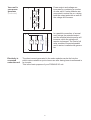
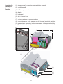
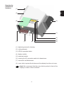
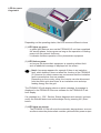
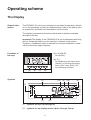
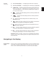
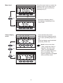
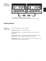
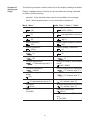
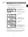
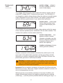
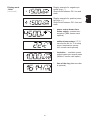
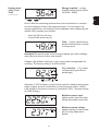
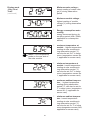
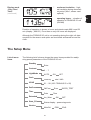
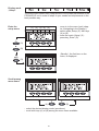
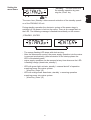
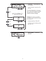
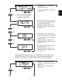
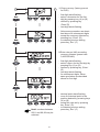
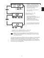
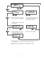
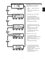
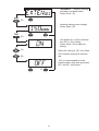
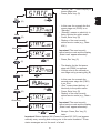
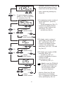
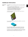
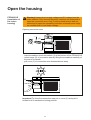
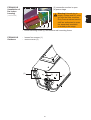
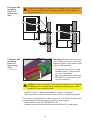
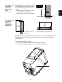
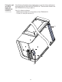
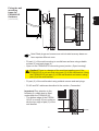
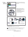
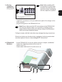
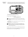
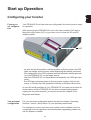
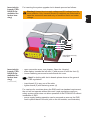
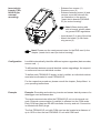
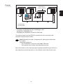
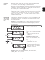


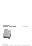
![FRONIUS IG US [42,0410,1089]](http://vs1.manualzilla.com/store/data/005774043_1-689bd6c2a055f0ab88c64924d7fd22c0-150x150.png)
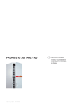
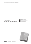


![Fronius Galvo:, , [42,0426,0171,PB]](http://vs1.manualzilla.com/store/data/006075295_1-029e1a27c983956f9c7f504114db1b65-150x150.png)