1
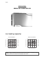
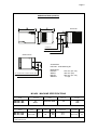
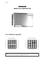
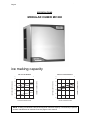
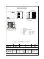
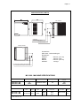
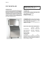
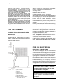
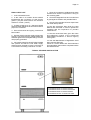
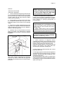
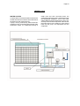
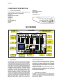
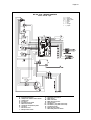
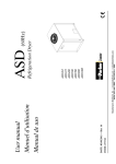
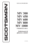
Page 1
Page 1
SERVICE MANUAL
MV 300
MV 450
MV 600
MV 800
MV 1000
R 404 A VERSION
Electronic
modular cubers
MS 1000.24 MS 1000.77 - REV. 12/04
Page 2
Page 2
TABLE OF
CONTENTS
Table of contents
Specifications
FOR THE INSTALLER
Introduction
Storage bin
Standard legs
Important operating requirements
Select location
Storage bin
Ice machine
Stacking instructions
Final check list
FOR THE PLUMBER
Conform to all applicable codes
Water inlet
Drains
For the electrician
Electrical connections
2
3-4-5-6-7-8-9-10-11-12
13
13
13
13
14
14
14
14
16
15
15
15
START-UP
Start-up cycle
Freezing cycle
Harvest cycle
17
17
17
OPERATION
Refrigeration during freeze
Water system
Refrigeration system during harvest
Water system
Control sequence
Alarm conditions
PC Board set up
19
20
20
20
20
22
22
SERVICE SPECIFICATIONS
Component
Operating characteristics
24
24
COMPONENT DESCRIPTION
Component description
25
WIRING DIAGRAM
MV 300-450-600-800-1000 air/water cooled
MV 800-1000 air/water cooled
28
29
SERVICE DIAGNOSIS
Service diagnosis
30
MAINTENANCE & CLEANING INSTRUCTION
Icemaker
Ice storage bin
Cabinet erxterior
Cleaning (Icemaker)
31
31
31
31-32
Page 3
Page 3
SPECIFICATIONS
MODULAR CUBER MV 300
ice making capacity
Kg.
10
130
21
110
32
90
38
70
32
27
21
15
WATER TEMPERATURE
10 °C
ICE PRODUCED PER 24 HRS
130
°C
AMBIENT TEMPERATURE
ICE PRODUCED PER 24 HRS
Kg.
140
WATER COOLED MODELS
°C
10
21
120
32
110
38
100
90
32
27
21
15
AMBIENT TEMPERATURE
AIR COOLED MODELS
10 °C
WATER TEMPERATURE
NOTE. To keep your Modular cuber performing at its maximum capacity, it is necessary to perform
periodic maintenance as outlined on the last pages of this manual.
Page 4
Page 4
SPECIFICATIONS (CONT'D)
AIR COOLED
CORD SET
3/4” GAS WATER INLET
WATER OUTLET
WATER COOLED
Accessoires
KSC 300 - Cube stacking kit
Dimensions:
HEIGHT
WIDTH
DEPTH
WEIGHT
3/4” WATER INLET WATER COOLED ONLY
3/4” WATER DRAIN WATER COOLED ONLY
575 mm. (22" 1/2)
560 mm. (22")
620 mm. (24" 1/2)
55 Kgs.
MV 300 - MACHINE SPECIFICATIONS
Model
MV 300 - AS
MV 300 - WS
Model
MV 300 - AS
MV 300 - WS
Finish
Comp. HP
Water req.
lt/24 HR
Stainless Steel
3/4
300*
1500*
Cond. unit
Air
Water
Basic
electr.
amps
Start
amps
watts
Electric power cons.
Kwhx24 HR.
N. of wires
Amps
Fuse
220-240/50/1
3,8
3,3
20
780
650
18.7
15.6
3x1,5 mm2
10
Cubes per harvest: 132 Full - 264 Half
* With water at 15°C
Page 5
Page 5
SPECIFICATIONS
MODULAR CUBER MV 450
ice making capacity
AIR COOLED MODELS
WATER COOLED MODELS
°C
Kg.
21
180
160
32
140
38
120
32
27
21
15
WATER TEMPERATURE
10 °C
200
10
21
180
32
38
160
140
AMBIENT TEMPERATURE
10
200
ICE PRODUCED PER 24 HRS.
220
AMBIENT TEMPERATURE
ICE PRODUCED PER 24 HRS.
°C
Kg.
220
120
32
27
21
15
10 °C
WATER TEMPERATURE
NOTE. To keep your Modular cuber performing at its maximum capacity, it is necessary to perform
periodic maintenance as outlined on the last pages of this manual.
Page 6
Page 6
SPECIFICATIONS (CONT'D)
AIR COOLED
CORD SET
3/4” GAS WATER INLET
WATER OUTLET
WATER COOLED
Accessoires
KSC 450 - Cube stacking kit
Dimensions:
HEIGHT
WIDTH
DEPTH
WEIGHT
3/4” WATER INLET WATER COOLED ONLY
3/4” WATER DRAIN WATER COOLED ONLY
575 mm. (22" 1/2)
760 mm. (30")
620 mm. (24" 1/2)
77 Kgs.
MV 450 - MACHINE SPECIFICATIONS
Model
MV 450 - AS
MV 450 - WS
Model
MV 450 - AS
MV 450 - WS
Finish
Comp. HP
Water req.
lt/24 HR
Stainless Steel
7/8
340*
1900*
Cond. unit
Air
Water
Basic
electr.
amps
Start
amps
watts
Electric power cons.
Kwhx24 HR.
N. of wires
Amps
Fuse
220-240/50/1
6
5
29
1000
900
24.0
21.6
3x1,5 mm2
16
Cubes per harvest: 204 Full - 408 Half
* With water at 15°C
Page 7
Page 7
SPECIFICATIONS
MODULAR CUBER MV 600
ice making capacity
WATER COOLED MODELS
Kg.
10
300
290
21
260
230
32
200
38
170
32
27
21
15
WATER TEMPERATURE
10 °C
°C
280
10
21
260
32
38
240
220
AMBIENT TEMPERATURE
°C
ICE PRODUCED PER 24 HRS.
Kg.
320
AMBIENT TEMPERATURE
ICE PRODUCED PER 24 HRS.
AIR COOLED MODELS
200
32
27
21
15
10 °C
WATER TEMPERATURE
NOTE. To keep your Modular cuber performing at its maximum capacity, it is necessary to perform
periodic maintenance as outlined on the last pages of this manual.
Page 8
Page 8
SPECIFICATIONS (CONT'D)
AIR COOLED
CORD SET
3/4” GAS WATER INLET
WATER OUTLET
WATER COOLED
Accessoires
KSC 450 - Cube stacking kit
Dimensions:
HEIGHT
WIDTH
DEPTH
WEIGHT
3/4” WATER INLET WATER COOLED ONLY
3/4” WATER DRAIN WATER COOLED ONLY
575 mm. (22" 1/2)
760 mm. (30")
620 mm. (24" 1/2)
77 Kgs.
MV 600 - MACHINE SPECIFICATIONS
Model
MV 600 - AS
MV 600 - WS
Model
MV 600 - AS
MV 600 - WS
Finish
Comp. HP
Water req.
lt/24 HR
Stainless Steel
1 1/2
470*
2750*
Cond. unit
Air
Water
Basic
electr.
amps
Start
amps
watts
Electric power cons.
Kwhx24 HR.
N. of wires
Amps
Fuse
220-240/50/1
10
7.5
31
1600
1300
38.4
31.2
3x1,5 mm2
16
Cubes per harvest: 204 Full - 408 Half
* With water at 15°C
Page 9
Page 9
SPECIFICATIONS
MODULAR CUBER MV 800
ice making capacity
AIR COOLED MODELS
WATER COOLED MODELS
°C
Kg.
21
350
32
300
38
250
200
400
10
21
32
38
350
300
250
200
32
27
21
15
WATER TEMPERATURE
10 °C
32
27
21
15
10 °C
WATER TEMPERATURE
NOTE. To keep your Modular cuber performing at its maximum capacity, it is necessary to perform
periodic maintenance as outlined on the last pages of this manual.
AMBIENT TEMPERATURE
10
400
ICE PRODUCED PER 24 HRS.
450
AMBIENT TEMPERATURE
ICE PRODUCED PER 24 HRS.
°C
Kg.
450
Page 10
Page 10
SPECIFICATIONS (CONT'D)
760
620
69
475
725
725
AIR COOLED
WATER DRAIN
3/4 GAS POTABLE WATER INLET
CORD SET
139
451
WATER COOLED
Accessoires
KSC 800 - Cube stacking kit
3/4 WATER INLET - WATER COOLED ONLY
3/4” WATER DRAIN - WATER COOLED ONLY
Dimensions:
HEIGHT
WIDTH
DEPTH
WEIGHT
725 mm. (28" 1/2)
760 mm. (30")
620 mm. (24" 1/2)
97 Kgs.
MV 800 - MACHINE SPECIFICATIONS
Model
MV 800 - AS
MV 800 - WS
Model
MV 800 - AS
MV 800 - WS
Finish
Comp. HP
Water req.
lt/24 HR
Stainless Steel
2.5
650*
3300*
Cond. unit
Air
Water
Basic
electr.
amps
Start
amps
watts
Electric power cons.
Kwhx24 HR.
N. of wires
Amps
Fuse
380-400/50/3
5.5
26,5
2300
1900
55.2
45.6
5x1,5 mm2
10
Cubes per harvest: 289 Full - 578 Half
* With water at 15°C
Page 11
Page 11
SPECIFICATIONS
MODULAR CUBER MV 1000
ice making capacity
AIR COOLED MODELS
WATER COOLED MODELS
°C
Kg.
21
450
400
32
350
38
300
32
27
21
15
WATER TEMPERATURE
10 °C
10
21
32
38
450
400
350
AMBIENT TEMPERATURE
10
ICE PRODUCED PER 24 HRS.
500
AMBIENT TEMPERATURE
ICE PRODUCED PER 24 HRS.
°C
Kg.
500
300
32
27
21
15
10 °C
WATER TEMPERATURE
NOTE. To keep your Modular cuber performing at its maximum capacity, it is necessary to perform
periodic maintenance as outlined on the last pages of this manual.
Page 12
Page 12
SPECIFICATIONS (CONT'D)
AIR COOLED
CORD SET
3/4” GAS WATER INLET
WATER OUTLET
WATER COOLED
Accessoires
KSC 1000 - Cube stacking kit
Dimensions:
HEIGHT
WIDTH
DEPTH
WEIGHT
800 mm. (31" 1/2)
760 mm. (30")
620 mm. (24" 1/2)
104 Kgs.
3/4” WATER INLET WATER COOLED ONLY
3/4” WATER DRAIN WATER COOLED ONLY
MV 1000 - MACHINE SPECIFICATIONS
Model
MV 1000 - AS
MV 1000 - WS
Model
MV 1000 - AS
MV 1000 - WS
Finish
Comp. HP
Water req.
lt/24 HR
Stainless Steel
2.5
700*
3500*
Cond. unit
Air
Water
Basic
electr.
amps
Start
amps
watts
Electric power cons.
Kwhx24 HR.
N. of wires
Amps
Fuse
380-400/50/3
5.5
26.5
2500
2100
60.0
50.4
5x1,5 mm2
10
Cubes per harvest: 340 Full - 680 Half
* With water at 15°C
Page 13
Page 13
FOR THE INSTALLER
INSTALLATION NOTE: Allow 15 cm.
minimum space at sides and back for
ventilation and utility connections.
INTRODUCTION
These instructions provide the specifications and
the step-by-step procedures for the installation,
start up and operation for the SCOTSMAN
Model MV 300-450-600-1000 Modular Cubers.
The Models MV 300-450-600-800-1000 Modular
Cubers are quality designed, engineering and
constructed, and are thoroughly tested icemaking
systems, providing the utmost in flexibility to fit
the needs of a particular user.
STORAGE BIN
The MV 300 stack on top of Scotsman bin model
B 193; the MV 450-600-800-1000 stack onto
SCOTSMAN bin model B 393.
Refrigerant R 404 A
Charge per nameplate rating.
STANDARD LEGS: Furnished with storage bin.
Four legs screw into mounting sockets on cabinet
base. Provide 18.5 cm. (7’’) minimum height
including adjustable leveling foot.
Optional Kit Casters for B 393 (KRB 550) are
available on request.
IMPORTANT OPERATING REQUIREMENTS
MINIMUM
MAXIMUM
Air Temperature
10°C (50°F) 40°C (100°F)
Water Temperature
5°C (40°F)
35°C (90°F)0
Water Pressures
1 bar gauge
5 bar gauge
-10%
+10%
Electrical Voltage
Variations Voltage
rating specified
on nameplate
Extended periods of operation exceeding these
limitations constitues misuse under the terms of
Manufacturer’s Limited Warranty, resulting in a
loss of warranty coverage.
Page 14
SELECT LOCATION
The first step in installing the equipment is to
select the location. The purchaser of the unit will
have a desired spot in mind, check out that spot
to insure that it is:
- indoors, in an environment that does not exceed
the air and water temperature limitations for the
equipment.
- that the necessary utilities are available including
the correct voltage electrical power.
- that there be space around the installed machine
for service, 15 cm. minimum left, right, and rear
for air-cooled models.
Page 14
Remove first the ice deflector/evaporator cover
then the masking tape from the ice thickness
sensor.
STORAGE BIN
The Scotsman bins for these units are the B 193
and B 393.
Other bins may be available with bin tops to vary
the storage capacity. Lay the bin on its back,
using cardboard from the carton to support it,
screw in the legs.
Stand the bin upright, and correct any possible
small tears in the machine mounting gasket with
food grade silicone sealant.
ICE MACHINE
The use of a mechanical lift is recommended for
lifting the uncrated icemaker onto the bin.
Remove front, top and sides panels.
Place the unit directly onto the bin, align it with
the back of the bin. Locate the hardware package,
take out two mounting screws, and use them to
secure the Icemaker to the two sides of the bin.
See illustration below.
AIR BAFFLE
Install on the back side of the machine the air
baffle as per instruction provided with it.
Remove all shipping material as well as the
masking tapes from the ice deflector/evaporator
cover.
STACKING INSTALLATION
To stack a second MV onto the present one, first
remove the top panel from the lower machine.
Add a bead of food grade silicone sealant to the
top edges of the lower units freezing compartment. Lift the top machine onto the bottom
Page 15
Page 15
machine, (the use of a mechanical lift is
recommended for this step). Align the two
machines cabinets, and using the 2 screw from
the top units, hardware package, fasten the two
units together at the side cabinets.
Then make use of the Stacking Kit KSC 300,
KSC 450, KSC 800 and KSC 1000, to be mounted
as per fitting instructions included in their package,
respectively on MV 300, MV 450-600, MV 800
and MV 1000 located in the bottom for proper
conveying, of the ice cubes made by the top unit,
into the storage bin.
With food grade silicone perfectly seal the edge
between the freezing compartment of the upper
machine and of the bottom machine so to avoid
any possible leak of water through the clearence
in between.
When choosing the water supply for the MV
Cuber, consideration should be given to:
A. Length of run.
B. Water clarity and purity.
C. Adequate water supply pressures.
Since water is the most important single ingredient
in producing ice you cannot over emphasize the
three items listed above. Low water pressure,
below 1 bar may cause malfunction, of the
icemaker unit. Water containing excessive
minerals will tend to produce cloudy colored ice
cubes, plus scale build-up on parts in the water
system.
Heavily chlorinated water can be controlled using
charcoal or carbon filters.
DRAINS
FOR THE PLUMBER
CONFORM TO ALL APPLICABLE CODES
WATER INLET
AIR-COOLED MODELS: The recommended
water supply is cold water connected to
the - 3/4'’ gas - male fitting at the back of the
cabinet. Install a hand valve near the machine to
control the water supply.
AIR-COOLED MODELS: There is one 20 mm.
dia sump drain fitting at the back of the cabinet.
Insulations in high humidity areas is recommended. The ideal drain receptacle would be a
trapped and vented floor drain.
WATER-COOLED MODELS: Besides the above
drain, a separate condenser drain must be run.
Connect it to the - 3/4'’ gas - condenser drain
connection at the back of the cabinet.
STORAGE BIN: A separate gravity type drain
needs to be run, similar to the air-cooled sump
drain. Insulation of this drain line is recommended.
FOR THE ELECTRICIAN
ELECTRICAL CONNECTIONS
The unit come equipped with an electrical cord
for power supply. The lead wires must be
connected to an electrical plug that corresponds
to the local electrical codes and requirements or
to a separate two poles disconnect box with
opening to the contacts of about 3 millimeters.
The disconnect box shoulds be placed close to
the selected ice maker location to be easily and
prompt reached.
Undersized wiring or unproperly installed
electrical circuit will result in major problems and
malfunctions.
Voltage variations shoud not exceed ten percent.
1) Switch
2) Plug receptacle
3) Electrical plug
4) Water inlet
5) Shut-off valve
6) Water filter
7) Water outlet line
8) Bin water outlet line
9) Open vented water drain
10) Water outlet from the condenser:
water cooled version only.
IMPORTANT - All plumbing and electrical
connections must be made by licensed
plumbers and electricians, this one must
follow the electrical specifications printed
on the ice maker nameplate.
NOTE: All SCOTSMAN Cubers require a
neutral wire and a solid earth ground wire to
prevent possible severe Electrical Shock
Injury to individuals or extensive damage to
equipments.
Page 16
Page 16
7. Have the compressor holddown bolts been
checked to be sure the compressor is snug on
the mounting pads.
FINAL CHECK LIST
1. Is the cabinet/bin level?
2. Is the cuber in a location where ambient
temperatures are a minimum of 10°C (50-degrees F.) all year around and to not exceed a
maximum of 40°C. (100°F.).
3. Is there at least a 15 cm. clearance behind
and around the cabinet for all connections and for
proper air circulation?
4. Have all electrical and piping connections
been made?
5. Has the electrical power supply wiring been
properly connected and the voltage tested and
checked against the nameplate rating? Has the
unit properly grounded.
6. Is the water supply line shutoff valve installed
and opened and has the inlet water supply
pressure been checked to insure a minimum of
1 bar without exceeding a maximum of 5 bar.
8. Check all refrigerant lines and conduit lines
to gard against vibration and possible failure.
9. Has the cuber and the bin been wiped clean
with clean damp cloths?
10. Has the owner/user been given the User
Manual and instructed on how to operate the
icemaker and the importance of periodic
maintenance?
11. Has the owner/user been given the name
and telephone number of the Authorized
SCOTSMAN Distributor or Service Agency
serving him?
12. Has the Manufacturer’s Registration Card
been properly filled out?
Check for correct Model and Serial Numbers
from nameplate, then mail the completed card to
the Manufactured.
TYPICAL STACKING INSTALLATION
KIT STACKING KSC 300: TO STACK 2 MV 300's
KIT STACKING KSC 450: TO STACK 2 MV 450-600's
KIT STACKING KSC 800: TO STACK 2 MV 800's
KIT STACKING KSC 1000: TO STACK 2 MV 1000's
Page 17
Page 17
START-UP
3. Water is coming into the water through the
Water Inlet Solenoid Valve till the water reservoir
if filled up to the maximum level controlled by a
Water Level Sensor.
START-UP CYCLE
1. Open the water tap/valve and switch ON the
power on the electrical supply line.
2. The models MV 300 - 450 - 600 enter in the Start
Up mode with the PC Board energized as well as
the Green LED of the machine under power while
the models MV 800-1000 enter in 90 minutes delay
time controlled by a special Start-up Delay PC Board.
POWER
OPER.
BIN
FULL
ALARM
ALARM
HI
PRESS.
RE-SET
The Green LED of machine in operation is
energized too, blinking fast for 40 seconds.
NOTE: The models MV 800-1000 are equipped
with a compressor crankcase heater and a
Start up Delay PC Board set up at 90 minutes.
During the first 90 minutes only the
compressor crankcase heater is energized
warning up the compressor.
3. During the Start Up cycle the components in
operation are:
• Hot gas valve
• Water Drain Valve
• Water Pump
FREEZING CYCLE
1. After the Start Up cycle the machine enters
directly into the Freezing cycle with the following
components energized:
• Water Inlet valve
• Compressor
• Fan motor (in continuous operation for the first
3 minutes).
2. The LED energized are:
• Machine under power
• Machine in operation (steady)
4.
30 seconds later, the Water Pump starts up.
5. After few minutes (3-5) from the start up of
the freezing cycle, the Water Inlet Solenoid Valve is activated again for few seconds to re-fill the
water reservoir up to the maximum level so to
reduce any possibility of slush ice formation.
6. In the meantime the condenser sensor starts
to transmit the current to the PC Board keeping
in operation the Fan Motor in ON-OFF mode or
continuously according to the condenser temperature.
NOTE: Do not remove the evaporator
deflector cover as it will cause the switching
off of the machine at "STORAGE BIN FULL".
7. The machine remains in the freezing cycle
with the ice that become thicker till the two metal
plates of the Ice Thickness Sensor are covered
by the water cascading through the front surface
of the ice plate.
8. When the Power is transmitted back to the
PC Board continuously through the metal plates
of the Ice Thickness Sensor for more then 6", the
machine enters in the Pre-Harvest or directly into
the Harvest Cycle mode according to:
• FAN MOTOR IN ON-OFF MODE DURING
THE PREVIOUS FREEZING CYCLE
RISE UP THE CUT IN TEMPERATURE OF
THE CONDENSER SENSOR TO 38°C (FAN
MOTOR OFF) AND EXTEND THE LENGTH
OF FREEZING CYCLE BY 30" MORE THEN
GO INTO HARVEST CYCLE
• FAN MOTOR ALWAYS IN OPERATION
DURING THE PREVIOUS FREEZING CYCLE
GO STRAIGHT TO THE HARVEST CYCLE
9. First freezing time will range between 15
and 20 minutes.
Longer time for temperature above 25°C and
shorter time required when temperature are below
25°C.
Average complete cycle time is about 22 min.
HARVEST CYCLE
1. During the harvest cycle the components in
operation are:
• Hot Gas valve
• Water Drain/Purge Valve
• Water Pump for the first 40"
• Compressor
Page 18
and both
• Machine Under Power
• Machine in Operation
2. 30 seconds after the beginning of the Harvest
Cycle, the Water Inlet Solenoid Valve is energized
for 10 seconds only in order to have a short flush
of fresh water into the sump while the Water
Pump is still in operation.
3. The Fan Motor remains in OFF mode unless
the Condenser Sensor probe rise up to more
then 38°C (same set up as per end of freezing
cycle).
4. When the ice plate is falling down from the
evaporator, the magnetic switch is activated for a
while providing the signal to the PC Board to
restart a new freezing cycle.
5. Observe first ice cube harvest and check
size of ice cubes; if an adjustment is required
thread down or out screw N. 1 as shown on below
illustration.
Page 18
NOTE: This type of machine produce an "ICE
PLATE" that breaks when falls down into the
storage bin. Setting the ice thickness sensor
in order to have single ice cubes may
cause malfunction of the machine.
6. Observe second and third cube harvest.
Check if size and shape combination is correct.
In areas where extreme problem water conditions
exist, filtering or purifyng equipment is
recommended.
NOTE: If water used is too soft,
"demineralized" the ice thickness sensor
might not be able to sense the water on its
reeds, there by it will not switch the unit on
harvest cycle.
A safety system built in the P.C. Board
switches the unit on harvest cycle whenever
the freezing period gets longer then 30' or 40'.
NOTE: To assure a correct operation of the
machine the water must have a minimum
electrical conductivity of 20 us.
7. Check operation of magnetic switch
controlling it by keeping open the bottom end of
plastic deflector for more than 30 seconds. The
machine must switch off at storage bin full.
Release the plastic deflector. The machine should
restart in the freezing cycle mode within few
seconds going through a 3' delay time.
8. Place again all cabinet panels and screws
previously removed.
This screw position determines the distance
between the sensor reeds and the egg-crate
evaporator thus keeping the ice cube at a proper
thickness.
9. Thoroughly explain to owner/user the significant
specifications of the ice maker start-up, reset and
operation, going through the procedures in the
operating instructions.
Answer all questions about the ice maker by the
owner and inform the owner himseft of the name
and telephone number of the authorized service
agency serving him.
Page 19
Page 19
OPERATION
FREEZE CYCLE
REFRIGERATION SYSTEM SCHEMATIC
REFRIGERATION DURING FREEZE:
This ice machine employes either air or water as
a condensing media, the refrigeration system for
either one is a follows:
At the hermetic compressor, Refrigerant is
compressed into a high temperature, high
pressure gas.
The gas moves through the discharge line into
the condenser, air or water-cooled. If air-cooled,
the discharge pressure will change with the heat
load and the ambient air temperature.
If water-cooled, the discharge pressure is
controlled by the amount of water flowing through
the condenser - which is determined by the
water regulating valve.
After the gas is cooled in the condenser, giving
up much of its heat, the gas condenses into a
high pressure liquid. This liquid travels through
the liquid line to the metering device, a
thermostatic expansion valve.
The thermostatic expansion valve meters how
much liquid refrigerant is to be allowed into the
evaporator section of the refrigeration system.
This is determined by the temperature of the TXV
sensing bulb, located on the suction line
manifold, at the outlet of the evaporator.
If the bulb senses a warm suction line, more
refrigerant is allowed into the evaporator, (common
at the beginning of the freeze cycle) and when the
temperature begins to fall, less refrigerant is allowed
through.
This is why the suction side gauge pressure will
decline throughout the freeze cycle. At the
evaporator, the liquid refrigerant released from
high pressure, boils off in the low pressure
environment and absorbs heat, thus cooling the
evaporator surface and anything near it, such as
water.
The low pressure refrigerant vapor then is
forced through the heat exchanger where any
excess liquid refrigerant boils-off, allowing only
refrigerant vapor to enter the compressor
suction tube, where it is recompressed into
high pressure, high temperature gas again
and the cycle repeats.
Page 20
Page 20
FREEZE CYCLE
WATER SYSTEM
A combination of a solenoid water inlet valve with
a water level sensor is used to control the level of
the water into the reservoir/sump.
A pump, running continuously, after the first 30"
of freezing cycle, forces the water to the top of the
evaporator, where it is distributed through a
water tube and then cascades down the
evaporator surface by gravity. As it flows accross
the refrigerated evaporator, some of the water
will be chilled enough to change form, turn to ice,
and stay frozen onto the evaporator cells. Most of
the water returns to the reservoir, to be sucked
back into the pump, and repumped over the
evaporator.
Page 21
Page 21
HARVEST (DEFROST) CYCLE
REFRIGERATION SYSTEM SCHEMATIC
REFRIGERATION SYSTEM DURING
HARVEST
The refrigeration system performs the harvest of
ice by use of a hot gas bypass valve. When the
time comes to de-ice the evaporators, the hot
gas valve is energized, and the high temperature, high pressure gas bypasses the condenser,
and is allowed directly into the evaporator. The
high pressure gas is cooled by the cold evaporator
so it condenses into a liquid, giving up its heat as
it does so. This heat warms the evaporator and
the ice frozen onto the evaporator surface melts,
releasing the frozen cubes. Ice then falls by
gravity into the storage bin.
The liquid refrigerant goes through the suction
line into the heat exchanger where it boils-off so
that only refrigerant vapor is drawn into the
suction tube of the compressor.
WATER SYSTEM
During the harvest cycle, the electric water
drain valve is energized thereby opening the
drain line.
All water remained in the reservoir at the end of
freezing cycle is pumped-out, to the waste,
through the water solenoid and drain line during
the first 40 seconds of the defrost cycle eliminating
any possible build-up and accumulation of
minerals concentration and impurities in the water
reservoir.
The water inlet valve is energized during the last
10" of the operation of the water pump so to rinse
the water tank with new fresh water.
When the released ice cubes drop into the bin,
they open-up for a fraction of a seconds the
bottom end of plastic deflector.
This deflector swinging motion is enough to reset
the contact of the magnetic switch which - via
electronic control board - deenergizes the water
drain valve allowing the unit to initiate a new
freezing cycle.
The harvest cycle lasts about 1.5÷2 minutes.
CONTROL SEQUENCE
At the start of the freezing cycle, the contacts of
the magnetic switch mechanically operated by
Page 22
POWER
the actuator plate of the deflector cover are
closed, thereby - via electronic control board closing the circuit to the main contactor coil and
consequently to the compressor and fan motors
and 30" later, to the water pump motors.
Then, as the ice thickness reaches the value that
corresponds to the full cube size, the film of water
that constantly cascades over the slab of ice
formed on the evaporator, arrives to establish a
contact between the two fingers (energised at
low voltage) of the ice sensor control, located on
the front upper right side of the evaporator. If the
contact between the two fingers of the ice sensor
remains established - by the film of water - for
more than 10 seconds, a small relay of the
electronic board, get energized, controlling simultaneously both the hot gas valve and the
water drain valve.
NOTE: in case of failure of ice level sensor,
the P.C. Board turns - on automatically the
unit into the defrost cycle when the freezing
cycle reaches 30 or 40 minutes according to
the operation of the fan motor during the
freezing cycle.
At this point, the unit initiates the defrost cycle.
The hot gas circulating into the evaporator
serpentine causes a slight melting of ice cubes
which get released from their molds. Once entirely
released the ice cubes drop simultaneously into
the ice storage bin below; by doing so they move
apart from the evaporator bottom end the plastic
deflector. This plastic deflector has on its side a
magnetic switch that on account of the deflector
swinging motion, caused by the ice while dropping
in the bin, opens and closes their contacts. This
will, in turn, disactivate the relay contacts that
controls the hot gas and water drain valve which
get deenergized allowing the unit to start a new
freezing cycle.
When the ice bin is full of ice, the last batch of ice
cubes released from the evaporator accumulates
to keep the bottom end of the plastic deflector in
open position; with the magnetic switch contacts
open for longer than 30'’ the entire unit stops with
the glowing of the corresponding LED.
The machine will restart when the ice deflector will
be back in its normal vertical position provided
that 3' are elapsed from unit stop. If not the
machine will delay its restart till 3' are elapsed with
the blinking of the green LED.
ALARM CONDITIONS
POWER
OPER.
BIN
FULL
ALARM
ALARM
HI
PRESS.
OPER.
BIN
FULL
Page
Page22
20
ALARM
ALARM
HI
PRESS.
RE-SET
Both the last two Red LED are BLINKING SLOW:
WATER ERROR
Water level inside the water sump too low after 3'
from the activation of the Water Inlet Valve.
Both the last two Red LED are BLINKING FAST:
RESET MODE: Charging water through the Water
inlet Solenoid Valve after the tripping OFF on
WATER ERROR
POWER
OPER.
BIN
FULL
ALARM
ALARM
HI
PRESS.
RE-SET
The fourth Red LED is ON STEADY: Harvest
Cycle longer then 3' 30"
The fourth Red LED is BLINKING SLOW: TOO
HI CONDENSING TEMPERATURE. The
condenser sensor detected a temperature > 65°C
The fourth Red LED is BLINKING FAST:
RESET MODE: Condenser Sensor < 50°C Fan
motor in operation for 3' then back on Start Up
Cycle Mode
POWER
OPER.
BIN
FULL
ALARM
ALARM
HI
PRESS.
RE-SET
The fifth Red LED is ON STEADY: TOO HI
DISCHARGE PRESSURE > 33 bar 460 PSI
The fifth Red LED is BLINKING FAST:
RESET MODE: After pushing the Reset
Button of the Pressure Control first the fan
motor starts up for 3' then back on the Start
Up Cycle Mode.
The PC Board is also checking the maximum
time of the freezing cycle that changes according
to the operation of the fan motor during the
freezing cycle (room temperature):
• Fan motor in
ON-OFF mode:
Max. freezing cycle length
equal to 30'
• Fan motor ON
All the time:
Max. freezing cycle length
equal to 40'
RE-SET
Both the last two Red LED are ON STEADY:
Condenser Sensor OUT OF ORDER.
Whenever the machine remains in the Freezing
Cycle for the Maximum time (30 or 40 minutes),
the PC Board moves the unit directly into the
Harvest Cycle.
Page 23
Page 23
PC BOARD SET UP
The PC Board can be set up for:
AUTOMATIC RESET MODE
• Manual Reset Mode (Jump IN)
The Automatic Reset Mode is activated only for
the following ALARM CONDITIONS:
• WATER ERROR
• TOO HIGH CONDENSING TEMPERATURE
• TOO LONG HARVEST CYCLE
WATER ERROR
The machine remains in OFF mode for 30' then it
tries to re-fill water:
YES: Machine remains in operation
NO:
Machine again in OFF mode for additional 30'
• Automatic Reset Mode (Jump OUT)
TOO HI CONDENSING TEMPERATURE:
As soon as the temperature of the Condenser
Sensor is < 50°C, the PC Board starts up first the
fan motor for 3' then the entire machine through
the Start-Up Cycle Mode.
TOO LONG HARVEST CYCLE:
After the 3' 30" of the Harvest Cycle, the PC Board
move back the machine into a new Freezing
Cycle.
MANUAL RESET MODE
To Restart the machine it is necessary to Push
the RESET BUTTON
➚
Page 24
Page 24
SERVICE SPECIFICATION
High Pressure Safety Switch.
MV 300: Cut IN 19 bar - Cut OUT 30 bar
MV 450-600-800-1000: Cut IN 23 bar - Cut OUT 33 bar
In servicing a machine, it is often, useful to
compare that individual units operating
characteristics to those of a normally operating
machine. The data that follows gives those
characteristics; however, be aware that these
values are for NEW, CLEAN machine operating
at 21 °C ambient and 15 °C water. USE THESE
NUMBERS AS A GUIDELINE ONLY.
OPERATING CHARACTERISTICS
On air-cooled models during the freezing cycle,
the discharge pressure is maintained between
two preset values by means of fan control
(condenser sensor); and at the same time, the
suction pressure will also decline reaching it’s
lowest point just before harvest. Compressor
amps experience a similar drop.
On water-cooled, the discharge pressure is
constantly, maintained during the freeze cycle by
the water regulating valve. However, suction
pressure and compressor amps, will still decline
as the machine freezes ice.
COMPONENT
Reservoir level
MV 300-450-600 ......................... 80 ÷ 85 mm
MV 800-1000 .............................100 ÷ 105 mm
Cube Size Control Ice Sensor - distance from
evaporator .........................................3 ÷ 5 mm
Disch.
Pressure
Freeze
max
Disch.
Pressure
Freeze
min
Hi
Pressure
CUT
OUT
Suction
Pressure
Beginning
Freeze
Suction
Pressure
end
Freeze
Freezing
time
MV 300 A
17,5 bar
14,0 bar
30 bar
4,3 bar
2,3 bar
15'
3,8
3,2
MV 300 W
16,5 bar
16,5 bar
30 bar
4,3 bar
2,4 bar
16'
3,6
3,1
MV 450 A
17,0 bar
15,0 bar
33 bar
3,6 bar
2,3 bar
16'
4,2
3,4
MV 450 W
16,2 bar
16,0 bar
33 bar
3,8 bar
2,5 bar
16'
3,9
3,3
MV 600 A
18,0 bar
16,0 bar
33 bar
2,9 bar
1,7 bar
11'
7,0
5,2
MV 600 W
16,5 bar
16,0 bar
33 bar
2,9 bar
1,7 bar
11'
6,5
5,2
MV 800 A
18,5 bar
15,5 bar
33 bar
2,9 bar
1,5 bar
11' 30"
3,9
3,0
MV 800 W
16,5 bar
16,5 bar
33 bar
2,9 bar
1,7 bar
11' 30"
3,4
2,6
MV 1000 A
18,0 bar
15,5 bar
33 bar
3,2 bar
1,7 bar
11' 30"
4,0
3,1
MV 1000 W
16,5 bar
16,5 bar
33 bar
3,2 bar
1,9 bar
12'
3,5
2,7
MODEL
Amps
Amps
Compressor Compressor
Beginning
end
Freeze
Freeze
Refrigerant charge R 404 A
MODEL
MV 300
MV 450
MV 600
MV 800
MV 1000
Air cooled 50 Hz
Air cooled 60 Hz
500
450
700
600
850
700
1300
xxxx
1600
1400
Water cooled 50 Hz
Water cooled 60 Hz
400
400
500
500
550
500
1000
xxxx
1200
1000
Refrigerant metering device
Thermostatic expansion valve.
NOTE: Always check nameplate on individual
icemachine for special refrigerant charge
before charging the refrigeration system.
Such refrigerant charge is the average charge
for the MV Modular Cubers. However it is
important to check nameplate for each
machine.
Page 25
Page 25
COMPONENT DESCRIPTION
1.
LED Nr. 5
Alarm high pressure.
BUTTON B
Reset/Washing.
Front Console Panel
Equipped with five LED plus a push button that
when glow or blink are monitoring:
LED Nr. 1
Electrical power supply.
LED Nr. 2
Operation.
LED Nr. 3
Bin full./Washing.
LED Nr. 4
Alarm.
MV SERIES
FAN
MOTORS
PC BOARD
COMPRESSOR, HOT GAS, WATER
INLET AND DRAIN VALVES
POWER IN
AND SAFETY
PRESSURE
CONTROLS
WATER
PUMP
N.O. - JUMP OUT
AUTOMATIC
N.C. - JUMP IN
MANUAL
FUSE
-
J2
+
WATER
SENSITIVITY
ADJUSTMENT
J1
FOR
FACTORY
USE ONLY
SERIAL
CONNECTOR
DISPLAY
CONNECTOR
ICE THICKNESS
SENSOR
WATER LEVEL
SENSOR
2. P.C. Board
Located in the control box, this board is the brain
of the system as it governs the ice machine
cyclematic through sensors, relays and switch.
It consists of two separated printed circuits one at
high and the other at low voltage integrated with
a fuse, of four connectors for the sensors/switches
(condenser sensor - BLACK -, magnetic switch
- GREEN - ice thickness sensor - RED - water
level sensor - BLUE), of two jumpers (one J1 for
factory use only - and the second J2 for the
selection between manual or automatic reset
mode), of one outlet connector (front LED display
- black) one serial port connector (black) and of
four plug in terminals for input and output power.
With J2 closed the P.C. Board is set up for
Manual reset mode. When J2 is open on
MAGNETIC
SWITCH
CONDENSER
SENSOR
Automatic Reset mode.
The P.C. Board is equipped by an electronic
safety timer that turns-on automatically the unit
to defrost cycle when freezing cycle is longer
then 30 or 40 minutes and trips-off completely
unit when defrost cycle is longer then 3,5 minutes
(4th Red LED ON).
A trimmer, located close to the transformer, can
change the current received back from the Ice
Tickness Sensor according to the Electrical
Conductivity of the water.
3.
Compressor Contactor
Located in the control box, the compressor
contactor functions to carry the compressor line
current. The contactor is wired to receive power
from the P.C. Board.
Page 26
Page 26
4. Ice Thickness Sensor
Located in the front upper right side off the
evaporator, the sensor is made with two metal
reeds in which passes power at low voltage. The
two metal reeds, which are individually insulated,
are set, through a setting screw, to maintain
a minimum clearence from the evaporator
(3÷5 mm). Once ice is formed into each mold and
is thick enough to fill-up that minimum clearance
existing between the two sensor reeds and the
evaporator, the water that cascades over the ice
has gradually approached to make contact
between the two sensor reeds.
It is enough that this contact remains there for
about 10 seconds that the P.C. Board receives
the signals to put the ice machine on defrost.
5. Magnetic Switch
Located in the front of the evaporator plastic
curtain, this switch sends a pulse to the P.C.
Board which switches the machine back in the
freezing cycle.
6. Hot Gas Solenoid Valve
The Hot Gas Solenoid Valve functions only during
the Harvest Cycle, to divert the hot discharge gas
from the Compressor, bypassing the Condendenser and thermostatic expansion valve, for direct
flow to the Evaporator Platen Assembly to release
ice cubes from the ice cube molds.
The Hot Gas Solenoid Valve is comprised of two
parts, the Body & Plunger and the Coil assembles.
Installed in the discharge line of the Compressor,
the energized solenoid coil lifts the valve stem
within the valve body to cause the hot discarge
gas to be diverted when the ice Thickness sensor
has signalled to the P.C. Board to start the
Harvest Cycle.
7. Condenser temperature sensor
The condenser temperature sensor probe
(located in contact with the condenser tube coil)
detects the condenser temperature variations
and signals them by supplying current, at low
voltage, to the P.C. BOARD.
In the air cooled versions, in relation to the
different current received, the micro processor of
the P.C. BOARD supplies, through a TRIAC, the
power at high voltage to the fan motor so to cool
the condenser and to reduce its temperature.
In case the condenser temperature rises and
reaches 65°C (150°F) the current arriving to the
micro processor is such to cause an immediate
and total stop of the machine operation with the
blinking of the Red LED.
8. High Pressure Control
The high Pressure Control, a safety control, is
factory set to cut-out, at 30 bar and cut-in at 22
bar. The control, functions as a precautionary
device to shut OFF electrical power to Icemaker,
should a loss of water occur to the water cooled
Condenser or a burnt out of the fan motor on air
cooled versions. The high Pressure Control is
manual reset with reset button located on the
rear side of the machine and a monitoring light on
the Front Console Panel.
9.
Water Regulating Valve
(Water Cooled Models)
The Water Regulating Valve functions maintain
a constant Compressor head pressure, by
regulating the amount of incoming water flow
through the Condenser, on water-cooled models.
The valve operate through the refrigerant system
high side pressure. Rotating the adjusting screw
located on top of the valve, can INCREASE or
DECREASE the water flow through the watercooled Condenser, which in turn, will DECREASE
or INREASE the Compressor operating head
pressure.
10. Water Distribution System
The Water Distribution System function to eventy
supply water to all cells of the evaporator plate.
The water pump pumps water from the sump to
the tee. From there water is channeled through
the vertical tygon tube to the water distributors,
above the evaporator plate, and from the holes in
the distributor tube water flows to the cells on one
side of the evaporator plate.
Gravity flow returns the unfrozen excess portion
of water to the sump reservoir for recirculation.
11. Water Drain Solenoid Valve
The Water Outlet Solenoid Valve functions in
conjunction with the water pump to flush-out the
sump assembly at the beginning (first 40") of
every harvest cycle. This action cleans-up and
rinses the sump during each harvest cycle preventing dangerous water minerales concentration.
12. Thermostatic Expansion Valve
The Thermostatic Expansion Valve regulates
the flow of refrigerant to the evaporator and
reduces pressure of liquid refrigerant from
condensing pressure to evaporating pressure.
13. Water pump
The water pump primes the water from the sump
to the water distributor tube and through the
distributing holes it cascades down onto the
evaporator cells by gravity so to be frozen into
clear ice cubes. The water pump remains off
during the first 30" seconds of the freezing cycle
(to avoid any cavitation problem) while it's kept
running during the first 40" of defrost/harvest
cycle to drain out (purge) the remaining water
from the sump (reach in mineral salts).
14. Water inlet solenoid valve - 3/4" male
fitting
The Water Inlet Solenoid valve is energised by
the P.C. Board during the beginning of the freezing
cycle till the water reaches the maximum level
into the sump (controlled by the Water Level
Sensor).
After 3 minutes, from the start up of the freezing
cycle, the Water Inlet Valve is energised again for
a short period to re-fill the sump with water till
Page 27
again to the max. level so to minimise any
possibility of slush ice formation
A flow control, fitted into its outlet port, reduces
the pressure of the water flow.
15. Water level sensor
The Water Level Sensor, located on the upper
right side of the water sump, works in conjunction
with the P.C. Board in order to control the water
level at beginning of the freezing cycle by receiving
a low power current passing through the water.
When the current reaches the PC Board, the
water inlet solenoid valve is de-energised.
In case the PC Board doesn’t receive any signal
(current) from the Water Level Sensor within the
first 3 minutes of the freezing cycle, the PC Board
trips OFF the operation of the machine with the
switching ON of the Water Error LEDs.
Page 27
16. Start up delay PC Board
Located in the back side of the unit it delays the
start up of the entire machine by 90' so to avoid
that compressor can start up w/out be
pre-heated.
17. Start up delay PC Board by-pass switch
Located in the back side of the machine allows to
by-pass the delay time controlled by the delay
PC Board.
WARNING. It is IMPERATIVE to by-pass
the delay time only when sure of proper
warm up of compressor.
Page 28
Page 28
MV 300/450/600/800/1000 - WIRING DIAGRAM
220 V. 50 Hz. 1 ph.
m
bc
gv
b
n
r
a
A
B
C
D
E
F
G
H
I
J
-
Input terminal board
Compressor contactor
Compressor
Ice sensor
End defrosting switch
Water level sensor
Condenser temperature probe
Led card
PC Board
Hi pressure switch
KL MNOPQRC CS CM-
=
=
=
=
=
=
=
brown
light blue
yellow green
white
black
red
orange
Manual/Automatic reset jumper
Water pump
Water inlet valve
Water drain/purge valve
Hot gas valve
Fan Motor (only AIR cooled unit)
Fan Motor (only WATER cooled unit)
Compressor relay
Start capacitor
Run capacitor
Page 29
Page 29
MV 800-1000 - WIRING DIAGRAM
400 V. 50 Hz. 3 ph.
m
bc
gv
b
n
r
a
v
A
B
C
D
E
F
G
H
I
J
-
Input terminal board
Compressor remote control switch
Compressor
Ice sensor
End defrosting switch
Water level sensor
Condenser temperature probe
Led card
Electronic card
Max pressure switch
KL MNOP1 P2 RST -
=
=
=
=
=
=
=
=
brown
light blue
yellow green
white
black
red
orange
purple
Automatic reset switch
Water pump
Water inlet valve
Water discharge valve
Hot gas valve
Fan Motor 1 (only AIR cooled unit)
Fan Motor 2 (only AIR cooled unit)
Cranckase heater
Delay by pass switch
Start delay electronic board
Page 30
Page 30
SERVICE DIAGNOSIS
The table below is intended as a quick reference
to aid the Service Agent in determining the cause
of a particular type of malfunction, as well as the
recommended repair. It is not intended to be an
exclusive list.
Reference to other portions of this manual,
inclusing wiring diagrams, installation, and
operation are recommended to better determine
the cause of a problem.
SYMPTOM
POSSIBLE CAUSE
CORRECTION
Warning Red LED ON
See page 20
See page 20
No warning LED/LIGHT ON
P.C. Board inoperative.
Remove board and check.
No power to unit.
Check electrical source.
Bin Full of ice.
Nome.
Magnetic switch inoperative.
Check and replace.
P.C. Board compressor
relay open.
Test and replace.
Compressor contactor open.
Test and replace.
Compressor relay open.
Test and replace.
Compressor winding open.
Test and replace.
Ice thickness control open.
Check sensor fingers
if are not covered
with scale sediment.
Too soft water.
Water electrical conductivity
must be higher then 20 µS.
Machine can't run with
demineralized water.
Built-in relay on
P.C. Board open.
Check and replace P.C. Board.
Machine runs, makes
and harvests ice
but very slowly.
Low refrigerant charge.
Check system for correct refr. charge.
Check for leak weight in charge.
Low ice capacity.
High discharge pressure
due to not-condensable
or overcharge.
Evacuate and weigh
in charge.
Inefficient compressor.
Replace.
Condenser dirty.
Clean.
Low water flow
(Water-cooled).
Check and repair.
High air temperature
(air-cooled).
Check temperature of air
entering condenser.
Plugged water distributor.
Clean water distributor.
TXV supertheat wrong.
Adjust or replace.
Refrigerant charge low.
Adjust-check for leak.
recharge.
Bin full Yellow LED ON
Machine runs, compressor
does not.
Machine runs, makes ice,
does not try to harvest.
Machine makes irregular ice.
Page 31
Page 31
MAINTENANCE & CLEANING & SANITATION INSTRUCTIONS
A SCOTSMAN Ice System represent a sizable
investment of time and money in any company’s
business. In order to receive the best return for
that investment, in MUST receive periodic
maintenance.
It is the USER’S RESPONSIBILITY to see that
preferable, and less costly in the long run, to
avoid possible down time by keeping it clean,
adjusting it as needed and by replacing worn
parts before they can cause failure. The following
is a list of recommended maintenance that will
help keep your machine running with a minimum
of problems.
Maintenance and Cleaning should be scheduled
at MINIMUM twice per year while sanitation once
per month.
8. Check cube size, adjust if required through
setting screw of ice thickness control sensor.
ICEMAKER
CABINET EXTERIOR
THE FOLLOWING MAINTENANCE SHOULD
BE SCHEDULED AT LEAST TWO TIMES PER
YEAR ON THIS ICEMAKER. CALL YOUR
AUTHORIZED SCOTSMAN SERVICE
AGENCY.
Wipe clean unit and bin cabinet exterior with a
clean cloth or disposable paper wipers, soaked
in warm water with mild detergent solution.
9. With unit out of operation, clean the
condenser using vacuum, cleaner, wisk broom
or brush.
Instruct customer to clean condenser frequently
DO NOT USE A WIRE BRUSH.
ICE STORAGE BIN
The interior liner of the bin is in contact with a food
product, ice, and should be cleaned and sanitised
regularly. Once a week sanitise it with a
commercial food grade sanitiser compling with
the manufacturer dilution.
CLEANING - Ice maker
1. Check and clean or service any optional
water treatment devices, if any installed.
2.
WARNING - Ice Machine Cleaner contains
Phosphoric and Hydroxyacetic acids.
These compounds are corrosive and may
cause burns. If swallowed, DO NOT induce vomiting. Give large amounts of water
or milk. Call physician immediately. In
case of sxternal contact, flush with water.
KEEP OUT OF THE REACH OF CHILDREN.
Clean water strainer.
3. Check that the cabinet is level, in the sideto-side and front-to-back directions.
4. Clean/Sanitise the water system, evaporator
plate and sump assembly, using a solution ot Ice
Machine Cleaner/Sanitiser. Refer to CLEANING Icemaker.
NOTE: Cleaning/Sanitising requirements
vary according to local water conditions and
individual user operation.
Continuous check of the clarity of ice cubes
and visual inspection of the water system
parts, evaporator plates and the sump
assembly before and after cleaning will indicate frequency and procedure to be followed
in local areas.
5.
Check and tighten all bolts and screws.
6.
Check for water leaks and make corrections.
7. Check the bin control to test shut-off.
Holding the evaporator deflector in open Position
for more that 30", shold cause the ice maker to
shut-off.
Once the evaporator deflector is released in its
closed position, the ice maker will restart.
1.
Empty bin of ice.
2.
Remove front panel.
3. Wait till the end of the defrost/harvest cycle
then push the RESET BUTTON for 6-8 seconds.
The machine should stop with the blinking of the
Yellow LED (slow blink).
4. Pour on
- MV 300
150 cc
- MV 450-600
250 cc
- MV 800-1000
350 cc
of Scotsman Ice Machine Clea-ner directly into
the reservoir then push again the RESET
BUTTON for a while. The water pump starts to
operate with the fast blinking of the Yellow LED
while the water inlet valve will be energized till the
fill up of the water sump.
5. After 15 minutes push the RESET BUTTON
for a while. The P.C. Board put the machine in
automatic rinsing mode with the special blinking
(blink twice and repeat) of the Yellow LED.
Page 32
NOTE: RINSING mode consists of:
a) energize the water drain valve and the
water pump for 40 seconds to empty the
reservoir
b) deenergize the water drain valve and the
water pump for 1 minute
c) energize the water inlet valve till the fill up
of the water sump
d) energize the water pump for 1,5 minutes.
The above sequence is repeted 7 times so to
be sure to have removed any possible trace
of Ice Machine Cleaner.
6. At the end of the 7th Rinsing cycle the P.C.
Board stops the operation of the machine with
the blinking (slow) of the Yellow LED.
Page 32
7. Pushing the RESET BUTTON for 6-8
seconds the machine restarts in the freezing
cycle.
8. Replace the evaporator cover deflector and
front panel.
9. Check the next batch of cubes to be sure all
the cleaner is gone (no sour taste).
CAUTION - DO NOT use ice cubes
produced from the cleaning solution. Be
sure none remains in the bin.
10. Pour hot water into the storage bin melt the
cubes, and to also clean the bin drain.