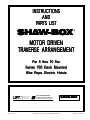
1
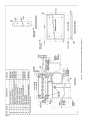
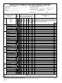
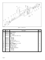
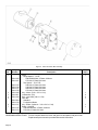
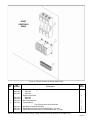
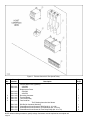
INSTRUCTIONS
AND
PARTS LIST
SHAW-BOX
®
MOTOR DRIVEN
TRAVERSE ARRANGEMENT
For 5 thr
u 10 TTon
on
thru
Series 700 Deck Mounted
e Rope Electric Hoists
ire
Wir
LIFT-TECH INTERNATIONAL
Division of Columbus McKinnon
MUSKEGON, MICHIGAN 49443
APRIL, 1993
COPYRIGHT 1991, LIFT-TECH INTERNATIONAL, INC.
SHA
W-BO
X
SHAW
-BOX
PART NO. 113533-76
Page 2
12578
Figure A.
THE INFORMATION CONTAINED IN THIS MANUAL IS
FOR INFORMATIONAL PURPOSES ONLY AND LIFTTECH INTERNATIONAL, INC. DOES NOT WARRANT
OR OTHERWISE GUARANTEE (IMPLIEDLY OR EXPRESSLY) ANYTHING OTHER THAN THE COMPONENTS THAT LIFT-TECH MANUFACTURES AND ASSUMES NO LEGAL RESPONSIBILITY (INCLUDING,
BUT NOT LIMITED TO CONSEQUENTIAL DAMAGES)
FOR INFORMATION CONTAINED IN THIS MANUAL.
TO BUILD MOTOR DRIVEN TRAVERSE
ARRANGEMENT
GENERAL
The following items are required for assembly of the traverse arrangement: One Series 700 deck mounted wire
rope electric hoist, one driver truck, one trailer truck, one
gear box and one motor, an optional brake may be furnished. The builder will have to furnish the material required for mounting the electrical enclosure and, if required, material for mounting a resistor. The resistor is
required for three speed hoists only.
The builder must also furnish a means of supplying power
to the traverse. This will be collectors, festooned cable or
cable reel.
holes. Bolt hoist down with hardware furnished with trucks.
See Figure B.
MOUNTING CONTROL PANEL
Refer to Figure C. If hoist is single or two speed, builder
need supply only item A and four bolts, lockwashers and
nuts (item H, J and K) for securing control panel.
For a three speed hoist, all the material listed in Figure C
is required. The additional material is required for the
secondary resistor.
Using first quality steel, free of rust and mill scale, fabricate the required material and assemble on the trailer
truck as shown on Figure C. It is strongly recommended
that any welding be done by qualified welders.
The control module for traverse control is mounted in the
control panel.
BALLAST RESISTOR MOUNTING – OPTIONAL
The ballast resistor for the traverse is an optional item. If
ordered, all material listed in Figure D is required for
mounting and must be furnished by the builder.
Using first quality steel, free of rust and mill scale, fabricate the required material, and then assemble the material on the traverse gear case unit as shown in Figure D.
MOUNTING HOIST
Although some traverse trucks have more than one set of
mounting holes for the hoist, the specified hoist will match
only one set of holes.
ELECTRICAL
The traverse wiring diagrams are shown in 113533-78.
Place trucks, with mounting pads up, on supports that
allow the wheels to hang free. Orient the trucks as shown
in Figure A. With the gear case note (stenciled on trucks)
at the same end of both trucks, the driver truck is on the
right as the traverse is viewed from the gear case side.
Lower the hoist, with the gear case side properly oriented
to the notes on the trucks, onto the trucks, adjusting the
distance between the trucks to match the hoist mounting
Figure B.
Page 3
Page 4
Figure C. Electrical Enclosure and Resistor Mounting Arrangement
Page 5
Figure D. Ballast Resistor Mounting Arrangement
INSTALLATION OF MOTOR DRIVEN
TRAVERSE ARRANGEMENT
This manual contains important information to help you to
operate, maintain, and service the traverse arrangement
of your crane trolley. The hoist is covered in a separate
manual.
We recommend that you study the contents thoroughly
before putting the traverse into use. With proper installation,
application of correct operating procedures, and practicing
the recommended maintenance suggestions you will be
assured maximum service from your traverse.
The traverses described in this manual are intended for
indoor service. Traverses to be used for outdoor service
require special consideration.
IMPORTANT!
When ordering replacement parts be sure to include with
your order, the KEY NUMBERS, which are identified
elsewhere in this manual.
Information given in this manual is subject to change
without notice.
GENERAL DESCRIPTION
GENERAL: These traverses are designed to operate on
parallel bridge girders with 25# ASCE rails. Motor and
control are designed for 208V, 230V, 460V or 575V – 3
phase – 60 hertz power supply. The traverse is equipped
with a single or two speed motor, controlled from a pendant
push button station. The push button may be located on
the bridge or hoist traverse unit. Traverses described herein,
are built in rated loads from 5 thru 10 tons.
BASIC CONSTRUCTION: The traverse frame is of rolled
steel welded construction. The frame consists of two trucks
rigidly bolted to the hoist.
The traverse is driven by a motor and gear box attached
to one truck. This drives the truck axle by a hollow shaft
keyed to the axle.
INSTALLATION
GENERAL: Bridge girders on which these traverses will
operate must be amply strong to support traverse, hoisting
equipment and rated load. Traverse rails should be level
and parallel within ± 1/4". Rail joints must be smooth and
held firmly in alignment either by bolted splice bars or
welding. Rails should be securely fastened to the bridge
girders.
INSTALLING: The installation of the traverse on the crane
shall be performed only by qualified installer.
For information regarding attaching, lifting and moving the
loads during installation, refer to ANSI B30.2.0, Section 23.2 and other applicable codes.
Page 6
Consult the Manufacturer for the traverse weight and other
required information before attempting installation.
WARNING
Before installing traverse on bridge, lock runway
conductor disconnect switch in open (power
off) position.
Total weight of traverse and hoist should be checked
against lifting equipment selected for erection of traverse.
Immediately after traverse is placed on the traverse rails,
check wheel flange clearances to the rail. Clearance
between side of rail head and inside flange of wheel will
be 1/4" for a 25# ASCE traverse rail with wheel centered
on rail.
CONNECTING TRAVERSE TO ELECTRICAL
SERVICE: Traverse wiring diagrams are shown in
113533-78.
CAUTION
Verify that traverse is furnished for the same voltage,
frequency and phase as the traverse power supply.
Do not operate traverse until “Pre-Operation Checks”
below are made.
PRE-OPERATION CHECKS: After the hoist traverse unit
is connected to electrical service, the following preoperation checks should be made before operation:
1. Check collector system for proper adjustment to
maintain proper contact with conductors or check along
span for possible interference if power supply is cable reel
or festooned cable.
2. Make certain traverse stops have been installed and
that they are correctly located.
3. Check truck axles and oil level of gear box. If lubricant
is required, see LUBRICATION on page 11.
4. Inspect the traverse to make certain all bolted
attachments are properly tightened and all electrical
connections are secure.
5. The hoist unit should be checked as instructed in the
Hoist Manufacturer’s Instruction Manual. Check to make
sure that traverse wheels have proper clearance to rails
for freedom of operation.
6. The traverse wheels and the flange surface of crane
rails on which traverse wheels roll should be free of paint
to provide proper electrical ground. If the environment in
which the crane will operate is such as to impair the
contact between traverse wheel and crane girder, an extra
conductor should be provided for grounding purposes.
NOTE: This instruction also applies to the bridge
wheel and runway rail.
OPERATION
OPERATOR QUALIFICATIONS: Safe and efficient crane
operation requires skill, extreme care and good judgement,
alertness, concentration and knowledge of and rigid
adherence to proven safety rules and practices. No person
should be permitted to operate a crane or hoist:
1. who does not possess above characteristics.
2. who is not qualified or has handicaps that could
adversely affect such operation.
3. who has not been properly instructed.
4. who has not been informed and does not have a
thorough knowledge of all applicable safe operating
practices, including those in this book as well as hitching
equipment and practices.
NOTE: See applicable National, State and Local
Safety Codes and regulations for additional
requirements relating to Safe Operating Practices,
including American National Standards ANSI
B30.2.0 and ANSI B30.16 as published by
American Society of Mechanical Engineers.
OPERATING RULES: Operating rules listed below are
an earnest effort to encourage SAFETY and are not
intended to take precedence over individual plant safety
rules and regulations or rules set forth by various applicable
codes.
A good operator operates his crane as smoothly as
possible and knows and follows the suggested rules below
for safe, efficient crane handling.
See that the immediate area is clear before moving a
load. Do not lift loads over persons.
Avoid
bumping other cranes on a runway unless
specifically authorized to do so. Never move or bump
another crane having a warning sign displayed.
First be sure to hoist load high enough to clear all
workmen and obstructions before moving bridge or
trolley.
Energize each motion gradually and avoid abrupt, jerky
movements of the load.
Take up slack from sling and hoisting cables before
lifting load.
Yield to people in a working area; allow them time to get
out of danger.
F ollow operating and maintenance procedures described
in manufacturer’s manuals to operate and maintain
bridge, traverse and hoist.
I nspect crane frequently. Be alert for unusual or erratic
conditions. Be certain the crane is SAFE to operate at
all times.
Repair electrical apparatus or make other major repairs
only when specifically authorized to do so. Do not
change fuse sizes. Never attempt to close a switch
having a “DO NOT OPERATE” sign or card attached.
Stop crane, hoist or traverse under normal operating
conditions before engaging limit switches. Limit switches
are safety devices and should not be used as a normal
operating control.
T raverse the bridge and traverse to a position directly
T ake time to become familiar with performance and all
functions of the crane including safety devices.
over the load before starting to hoist. The hoisting
chain or rope should be kept vertical to avoid swinging
the load as the lift is started.
Hitch loads securely. This is the joint responsibility of the
hitcher and the crane operator. Never lift load with
loose slings or with sling hooks attached to crane
hook.
I f the brakes do not hold, do not operate crane. Report
defect immediately to supervisor.
CAUTION
Make sure all INSTALLATION AND OPERATION
CHECKS have been made before turning on power.
Never leave load hanging from crane or hoist when not
attended.
Know the safe capacity of crane and chain slings, rope
slings, etc. Do not make lifts above safe capacity of
crane or slings.
LEARNING THE CONTROLS: After making certain the
traverse is completely and properly installed with traverse
connected to power supply and all pre-operation checks
made, the operator should learn the controls.
Page 7
The operator should locate the runway disconnect and
make sure this switch is locked open (POWER OFF). The
operator should now operate the various push buttons to
get the “feel” and determine that they do not bind or stick
in any position. The operator should become familiar with
push button location for their respective motions as well
as “start” and “stop” buttons which operate the crane main
line contactor. The main line contactor will shut off power
to all motions.
WARNING
If any push button binds or sticks in any position
– Do not turn power on – Determine the cause
of malfunction and correct before operating
crane.
OPERATING THE CONTROLS (NO LOAD): Having
inspected and tried the pendant push button station, the
crane operator is now ready to try the crane under power.
Sixth – Operate traverse from one end of bridge to the
other, checking for obstructions or interferences. Proceed
with CAUTION and be prepared to stop short of any
obstructions. If traverse power is interrupted during traverse
travel, check traverse collectors for proper contact with
bridge conductors.
WARNING
Lock main runway disconnect switch in open
(power off) position before attempting to adjust
cross collectors or conductors.
Seventh – After making certain that all building and
structural clearances are adequate, practice going “Left”
and “Right” with push button depressed. Note the stopping
distance of the trolley without load.
After becoming familiar with these motions, the operator
can now depress the hoist “Up” button.
First – Close the crane runway disconnect switch.
Second – Close the crane disconnect switch.
Third – Press the start-push button which will close the
main line contactor, applying power to all control devices.
The traverse is now ready for further testing.
The traverse is powered by a single or two speed motor.
There is one button for each direction, labeled “Left” and
“Right”. Depressing either button will cause traverse to
operate.
CAUTION
ALWAYS ALLOW TRAVERSE TO COME TO A
COMPLETE STOP BEFORE CHANGING
DIRECTION. ABRUPT CHANGE OF TRAVERSE
DIRECTION WHILE IN MOTION, MAY CAUSE
ADVERSE OPERATING CHARACTERISTICS OR
DAMAGE TO TRAVERSE AND DRIVE
COMPONENTS.
Fourth – Momentarily depress traverse “Left” button.
Check to be certain motor runs in the proper direction.
Momentarily depress “Right” button. Check direction. To
reverse directions, interchange leads L1 and L2 in the
traverse panel.
WARNING
If, when depressing hoist “Up” button, the hook
should lower – STOP AT ONCE – Do not attempt
to operate again. Report this condition to proper
supervisor for correction with instructions
furnished with your hoist manual.
Depress the “Down” button, with hook moving downward
on multi-speed hoists, try to feel the steps in relation to
speed increase as push button is depressed further.
Hook may be lowered until TWO FULL WRAPS of cable
remain on the drum. Note position of hook and NEVER
LOWER HOOK BELOW THIS POSITION. (Some hoists
may have a lower limit switch which will stop hoist when
this position is reached. Consult Hoist Manufacturer’s
Manual.)
Depress the hoist “Up” button and slowly return the hook
to near its high position. Continue to raise hook by slowly
inching. CAREFULLY OBSERVE the relationship of the
hook block and the bottom of the hoist frame. The hoist
upper limit switch, when working properly should cause
the hoist up motion to stop and/or reverse direction.
WARNING
WARNING
Lock crane main switch open (power off) before
reversing leads.
Fifth – To check that electrical connections have been
properly made, operate traverse cautiously on bridge.
Watch for any obstructions or interferences between
traverse and building parts. Depress “Left” button slightly
– traverse will travel along bridge.
Page 8
Do not contact or strike hoist frame with hook
block. If hoist motion is not interrupted by limit
switch, stop hoist by removing finger from
button and/or depressing the STOP button. Do
not attempt further operation until limit switch
is operable. Consult Hoist Manufacturer’s
Instructions.
Repeat upper limit switch test described above at full
speed.
INSPECTION
WARNING
During this test and under any other operating
condition – OPERATOR SHOULD NEVER BE
POSITIONED UNDER THE HOOK OR LOAD.
NOTE: Jogging is used excessively by some
operators for making “inching” crane movements.
AVOID EXCESSIVE USE OF JOGGING SINCE
IT MAY CAUSE PREMATURE BURNING OF
CONTACT TIPS AND MOTOR OVERHEATING.
The crane should be inspected at the beginning of each
shift. All functional mechanisms should be in good working
order. Check limit switches, brakes, electrical equipment,
and other SAFETY devices. Check crane operation without
load. Any unusual sounds, vibrations, anything wrong or
apparently wrong should be reported to the operators’
supervisor immediately. Inspect hoist as recommended in
manufacture’s hoist manual.
WARNING
WARNING
THIS EQUIPMENT IS NOT DESIGNED OR
SUITABLE AS A POWER SOURCE FOR LIFTING
OR LOWERING PERSONS.
OPERATING THE CONTROLS (WITH LOAD): Make
certain hook is high enough to clear any obstructions
below. Move the bridge to a position directly over the load,
and operate in the following sequence:
STEP 1: Spot the traverse and hoist over the load. If
control is suspended from the bridge, hand signals may
be required from ONE authorized floor man at the load.
Be certain load to be lifted is properly hitched and does
not exceed the rated capacity of the hoist, traverse or
bridge.
STEP 2: Slowly raise the hook until slack has been taken
out of slings. When floor man signals and operator is
satisfied load is secure in sling, he lifts the load slowly
until clear. Now, hoisting speed can be increased and
maintained until load is clear of all obstructions or floor
man gives the signal to stop.
STEP 3: Starting slowly and increasing speed as distance
permits, move the bridge toward the point where the load
is to be lowered. The stopping distance will be greater
than with no load on the hook.
STEP 4: Learn to judge the stopping distance of the
bridge and traverse, both with light loads and full loads.
This will enable you to “spot” loads with the minimum
amount of jogging.
NOTE: Refer to hoist manual for complete
operating instructions for hoist.
RESPONSIBILITY FOR SAFE OPERATION: Each crane
operator should be held directly responsible for the safe
operation of his crane. The crane operator should STOP
the crane and refuse to handle loads when:
1. there is any doubt as to SAFETY;
2. any unusual vibrations or sounds are noticed before
or when starting the lift or traverse motions;
3. there are arguments or disagreements with floor man
or hitchers;
4. he feels ill or is not alert.
Do not operate a crane, hoist or traverse having
unusual vibrations, sounds, warnings or with
anything wrong or apparently wrong. Danger
may be present that the crane operator cannot
see. Determine and correct cause of unusual
conditions and make certain the crane can be
operated SAFELY.
Complete inspection of the crane is to be performed at
least every six months and more frequently when
conditions require. Inspect areas listed below and any
other area which may be adversely affected due to activity,
severity of service and crane environment that could cause
unsafe crane operation.
WARNING
Always lock main switch in open (power off)
position before inspection.
Items to be inspected include, but are not limited to:
1. All functional operating mechanisms for maladjustment
interfering with crane operation.
2. Operating parts for excessive wear.
3. All safety devices for malfunction.
4. All connections and mountings for loose bolts, nuts or
other fasteners for tightness.
5. All structural members for deformation, cracks,
corrosion.
6. All electrical apparatus, including control contactors,
limit switches, push button stations for signs of pitted
contact points, wear or deteriorations.
7. All hoists and traverses installed on the crane in
accordance with manufacture's recommendations.
Written, dated and signed inspection reports should be
maintained on all critical items (such as safety devices,
brakes, hooks, ropes, chains, etc.). All worn, damaged or
malfunctioning parts should be repaired or replaced to
maintain a SAFE operating crane. Warning labels affixed
to the crane, hoist or traverse should be kept clean and
visible at all times. Warning labels should be replaced if
loose or illegible. A typical inspection Schedule and
Maintenance Report Form is shown on Page 10.
Page 9
INSPECTION SCHEDULE AND MAINTENANCE REPORT
CRANE SERIAL NO. (MFGRS) _______________________
RATED LOAD __________________
TYPE ________________________
VOLTAGE _____________________
*
Motor
Gears & Bearings
Wheels
Trucks
Girders & Connections
Footwalk & Handrail
Motor
Motor Brake
Mechanical Load Brake
Overload Clutch
Couplings
Gear, Shafts & Bearings
Upper Block
Lower Block
Hook & Throat Opening
Hoist Rope
Rope Drum
Guards
Limit Switch
Bridge Panel
Trolley Panel
Hoist Panel
Pushbutton
Wiring
Motor
Brake (when so equipped)
Couplings
Gear, Shafts & Bearings
Frame
Wheels
Bumpers
Guards
Conductors
Collectors
Monorail Joints
Monorail
Main Conductors
Main Collectors
General Condition
Load Attachment Chains
Rope Slings & Connections
Change Gearcase Lub.
Grounding Faults
X
See text for DAILY & WEEKLY REQUIREMENTS.
INSPECTION INTERVAL.
CLEANING OR
PAINTING
REQUIRED
LUBRICATION
REQUIRED
(Low Oil or Grease,
Rust or Corrosion)
REPLACEMENT
REQUIRED
(Worn or Damaged)
REPAIR REQUIRED
(Loose Parts or
Wires)
CONDITION
(Check column best indicating condition when
part or unit is inspected. Use note column to
the right if condition is not listed below.)
ADJUSTMENT
REQUIRED
ANNUAL
MONTHLY
SEMI-ANNUAL
LOCATION
MISC.
RUNWAYS
TROLLEY
CONTROL
PANELS AND
PUSH BUTTON
HOIST
BRIDGE
COMPONENT,
UNIT OR
PART
Recommended
Inspection
Interval
GOOD
*
COMPONENT, UNIT OR PART
and location
CUSTOMER CRANE IDENTITY NO. _______________________
LOCATION IN PLANT __________________________________
THIS INSPECTION IS MONTHLY X
ANNUAL X
SEMI-ANNUAL X
INSPECTED BY: ________________
DATE _____________
CORRECTIVE ACTION
NOTES
(Indicate corrective action taken during inspection and note date. For
corrective action to be done after inspection, a designated person must
determine that the existing deficiency does not constitute a safety hazard
before allowing unit to operate. When corrective action is completed,
describe and note date in this column.)
DATE
Record Hook Throat Opening
SIGNED & DATED REPORT REQUIRED – OSHA.
X MAGNETIC PARTICLE OR EQUIVALENT EXAMINATION REQUIRED.
Typical Inspection Schedule and Maintenance Report form.
User must adjust inspection interval and components to suit his individual conditions and usage.
Page 10
12382A
MAINTENANCE
(Ref. No. 1), in a groove in the axle. Remove retaining
ring.
GENERAL: Maintenance services required on traverses
are, for the most part, simple periodic inspections and
adjustments. Procedures for lubrication, routine adjustments and replacement of parts, if required, are described
in the following paragraphs.
4. Wheel is now free. Remove by sliding horizontally off
axle, maintaining a secure hold so that wheel does not
fall.
LUBRICATION: Motor bearings are lubricated for the life
of the bearing and require no additional lubrication.
Axle bearings are lubricated for the life of the bearing and
require no additional lubrication.
The gear box attached to the motor requires gear case oil
having a viscosity at 210½F of 125-150 SSU, viscosity
index at 90 and a pour point of 25½F (AGMA #7 Compound) at an ambient temperature of 50½ to 125½F. For
ambient temperatures outside this range, refer to the Manufacturer for recommendations.
General oiling should be performed every three months to
prevent rusting and provide limited lubrication for points
not having lubrication fittings nor considered normal wear
points. Pins, levers, rods, hinges and other linkages and
moving parts, where rusting could occur and interfere
with normal operation, should be oiled with a few drops of
oil. (Examples include, collector pins and linkage, limit
switch linkage, cable carriers, etc. Also see instructions
furnished with hoist.)
The frequency of oil changes in the gearhead unit and
axle bearing lubrication is dependent on crane usage. The
user should establish a lubrication interval based on individual conditions of usage and environment (including
airborne dirt, chemical dust, moisture, etc.), but this interval should never exceed six months. Also, drain and refill
gear box after first 100 hours of operation.
5. Remove key (Ref. No. 4).
6. Replace wheels in reverse procedure of disassembly.
Wheel at motor may be removed by using the above
procedure after the motor and gear box have been removed.
AXLE REMOVAL
(Refer to parts illustration, Figure 2.)
To remove axle, follow steps 1 through 4 listed below:
1. Remove both wheels on truck as described above.
2. One side of truck has a retaining ring (Ref. No. 7),
securing the axle bearing (Ref. No. 3). The axle (Ref. No.
5) may be removed by pushing axle toward opposite side
of truck. Maintain a secure hold on the axle so that it does
not fall.
3. If required, retaining ring may also be removed allowing removal of both bearings.
4. Replace axle in reverse procedure of disassembly.
It is recommended that bearings be replaced whenever
replacing wheels or axles.
The axle at the motor may be removed by using the
above procedure after the motor and gear box have been
removed.
GEAR BOX REMOVAL
(Refer to parts illustration, Figure 1.)
For hoist lubrication instructions refer to Hoist
Manufacturer’s Service Manual.
WHEEL REMOVAL
(Refer to parts illustration, Figure 2.)
WARNING
Main runway disconnect switch should be locked
open (power off) before working on gearmotor.
To remove wheels, follow steps 1 through 6 listed below:
1. Remove any load from hook.
WARNING
Make sure that traverse is adequately supported
so that it cannot drop when wheel is removed.
Also lock main runway disconnect switch in
open (power off) position when working on
wheels adjacent to runway conductors.
2. Remove load from wheel axle. This can be accomplished by jacking a small distance, just enough to clear
the wheel flanges.
To remove gear box:
1. Disconnect wiring and conduit at conduit box on motor.
2. Remove the four bolts and lockwashers holding the
top of the gear box to the mounting plate on the driver
truck.
3. Slide gear box and motor off axle extension taking
care not to drop it.
4. Remove key (Ref. No. 2).
5. Remove four bolts and lockwashers (Ref. Nos. 3 and
4) to separate motor from gear box.
6. Reassemble in reverse.
3. Wheel (Ref. No. 2) is held in position by retaining ring
Page 11
2. Traverse Control Panel
ELECTRICAL
a. For wiring diagrams for traverse panel, see
113533-78.
WARNING
b. All connections should be checked frequently for
tightness.
Main runway disconnect switch should be locked
open (power off) before working on electrical
equipment.
c.
unit.
Contactors should be replaced as a complete
1. Motors
a. The traverse is driven by a single or two speed
motor with a single worm gear box. The worm gear retards speed with power off and, therefore, a traverse brake
is not normally furnished.
It is recommended that if any work is required, the motor
be returned to the crane builder.
b.
For hoist motor, consult the hoist literature.
3. Optional Brake
If brake is furnished, reference brake literature for maintenance and replacement.
4. Hoist Panel, Brakes, Limit Switches
Consult hoist literature for maintenance and spare part
literature.
NOTES
Page 12
NOTES
REPLACEMENT PARTS
The following parts list and illustrations cover standard
model SHAW-BOX traverses. Typical units are used as the
basis for the exploded parts illustrations; therefore, certain
variations may occur from the parts information given. For
this reason always give the catalog number, model number, motor horsepower, voltage, phase and frequency when
ordering replacement parts. For motors, gear boxes, and
electrical components, give complete nameplate data.
The factory recommends complete replacement of the
motor or gear box.
The numbers assigned to the parts of our various
assemblies in our parts list are not the part numbers used in manufacturing the part. They are
identification numbers, that when given with the
catalog number, permits us to identify, select or
manufacture, and ship the correct part needed.
INDEX OF PARTS ILLUSTRATIONS
Figure
No.
Page
No.
Driver Truck ..........................................................................................................................................
Trailer Truck .........................................................................................................................................
1
2
14
15
Motor and Gear Box ............................................................................................................................
Traverse Controls for Single Speed Trolley ..........................................................................................
3
4
16
17
Traverse Controls for Two Speed Trolley ..............................................................................................
5
18
Title
Page 13
Figure 1. Driver Truck.
Ref.
No.
Key
Number
1
2
3
4
5
6
CBH-1101
CBH-1102
CBH-1103
CBH-1104
CBH-1105
7
8
9
10
11
12
13
14
15
CBH-1106
CBH-1107
CBH-1108
CBH-1109
CBH-1110
CBH-1111
CBH-1112
CBH-1113
CBH-1114
CBH-1115
CBH-1116
CBH-1117
CBH-1118
CBH-1119
Page 14
Description
Ring – Retaining
Wheel
Bearing – Ball
Key – Parallel
Key – Parallel (3/8 x 3/8 x 2-1/4)
Axle
48" Gage
66" Gage
78" Gage
Lockwasher (3/8)
Bolt – Hex Head (3/8-16 x 1)
Nameplate
Bolt – Hex Head (1/2-13 x 2-3/4)
Ring – Retaining
Washer – Bevel (1/2)
Lockwasher (1/2)
Nut – Hex (1/2-13)
Assembly – Trolley Beam
48" Gage
66" Gage
78" Gage
Qty.
Req’d
2
2
2
1
2
1
4
4
1
4
1
4
4
4
1
Figure 2. Trailer Truck.
Ref.
No.
Key
Number
1
2
3
4
5
CBH-1201
CBH-1202
CBH-1203
CBH-1204
6
7
8
9
10
11
CBH-1205
CBH-1206
CBH-1207
CBH-1208
CBH-1209
CBH-1210
CBH-1211
CBH-1212
CBH-1213
CBH-1214
CBH-1215
Description
Ring – Retaining
Wheel
Bearing – Ball
Key – Parallel (3/8 x 3/8 x 2-1/4)
Axle
48" Gage
66" Gage
78" Gage
Bolt – Hex Head (1/2-13 x 2-3/4)
Ring – Retaining
Washer – Bevel (1/2)
Lockwasher (1/2)
Nut – Hex (1/2-13)
Assembly – Trolley Beam
48" Gage
66" Gage
78" Gage
Qty.
Req’d
2
2
2
2
1
4
1
4
4
4
1
Page 15
Figure 3. Motor and Gear Box Assembly.
Ref.
No.
Key
Number
1
CBH-1360
CBH-1361
2
3
4
5
6
7
CBH-1375
CBH-1376
CBH-1377
CBH-1378
CBH-1366
CBH-1367
CBH-1368
CBH-1369
CBH-1370
CBH-1371
CBH-1372
CBH-1373
Description
Motor
Single Speed – .75 HP
208-230/460 Volts, 3 Phase, 60 Hertz
575 Volts, 3 Phase, 60 Hertz
Two Speed – .75/.37 HP
208 Volts, 3 Phase, 60 Hertz
230 Volts, 3 Phase, 60 Hertz
460 Volts, 3 Phase, 60 Hertz
575 Volts, 3 Phase, 60 Hertz
Key – Motor (3/16 x 3/16 x 1-1/4)
Lockwasher (3/8)
Bolt – Hex Head (3/8-16 x 7/8)
Gear Box
Standard
For Optional Brake
Key – Brake (Optional – 3/16 x 3/16 x 1-3/8)
Brake – Optional
208-230/460 Volts, 3 Phase, 60 Hertz
575 Volts, 3 Phase, 60 Hertz
ORDERING INSTRUCTIONS:
Page 16
Furnish complete data from motor and gear box nameplates with parts order.
Replacement parts cannot be provided without this information.
Qty.
Req’d
1
1
4
4
1
1
1
HOIST
CONTROLS
HERE
Figure 4. Traverse Controls for Single Speed Trolley.
Ref.
No.
Key
Number
1
CBH-1401
CBH-1402
2
3
CBH-1403
CBH-1404
CBH-1410
CBH-1411
CBH-1412
CBH-1413
CBH-1414
Description
Traverse Motor Fuse (Optional)
208/230V
460/575V
Replacement Fuses
208/230V
460/575V
Reversing Contactor
Terminal Board
The Following Items Are Not Shown:
DIN Rail for Contactor Mounting
Slotted Round Head Screws for DIN Rail (#10 - 32 x 3/8)
Slotted Round Head Screws for Terminal Block (#8 - 32 x 5/8)
Qty.
Req’d
1
3
1
1
1
3
2
NOTE: When ordering contactor, specify voltage. Contactor must be replaced as a complete unit.
Page 17
Figure 5. Traverse Controls for Two Speed Trolley.
Ref.
No.
Part
Number
1
CBH-1401
CBH-1402
2
3
4
5
CBH-1403
CBH-1404
CBH-1410
CBH-1411
CBH-1511
CBH-1512
CBH-1412
CBH-1413
CBH-1414
CBH-1513
Description
Traverse Motor Fuse (Optional)
208/230V
460/575V
Replacement Fuses
208/230V
460/575V
Reversing Contactor
Terminal Board
Time Delay Relay
Fast Contactor
The Following Items Are Not Shown:
DIN Rail for Contactor Mounting
Slotted Round Head Screws for DIN Rail (#10 - 32 x 3/8)
Slotted Round Head Screws for Terminal Block (#8 - 32 x 5/8)
Slotted Round Head Screws for Time Delay Relay (#8 - 32 x 7/8)
NOTE: When ordering contactors, specify voltage. Contactors must be replaced as a complete unit.
Page 18
Qty.
Req’d
1
3
1
1
1
1
1
3
2
2
NOTES
Page 19
Recommended Spare Parts
for Your SHAW-BOX Traverse
Certain parts of your traverse will, in time, require replacement under normal wear conditions. It is
suggested that the following parts be purchased for your traverse as spares for future use.
Description
Quantity
Contactor
Traverse Fuses (If Furnished)
1
3
Axle Bearings
4
NOTE: When ordering parts always furnish Catalog Number and Part Number.
Parts of your traverse are available from your local authorized SHAW-BOX repair station. For the location
of your nearest repair station, write:
In USA
LIFT-TECH INTERNATIONAL, INC.
PO BOX 769
MUSKEGON MI 49443-0769
or phone:
616-733-0821
In Canada
Lift-Tech International
Cranes & Hoist, Inc.
53-D Cowansview Road
Cambridge, Ontario N1R 7L2
519-621-3201
WARRANTY
WARRANTY AND LIMITATION OF REMEDY AND LIABILITY
A. Seller warrants that its products and parts, when shipped, and
its work (including installation, construction and start-up), when
performed, will meet applicable specifications, will be of good
quality and will be free from defects in material and workmanship.
All claims for defective products or parts under this warranty must
be made in writing immediately upon discovery and, in any event,
within one (1) year from shipment of the applicable item unless
Seller specifically assumes installation, construction or start-up
responsibility. All claims for defective products or parts when Seller
specifically assumes installation, construction or start-up responsibility, and all claims for defective work must be made in writing
immediately upon discovery and, in any event, within one (1) year
from completion of the applicable work by Seller, provided; however, all claims for defective products and parts must be made in
writing no later than eighteen (18) months after shipment. Defective
items must be held for Seller’s inspection and returned to the
original f.o.b. point upon request. THE FOREGOING IS EXPRESSLY
IN LIEU OF ALL OTHER WARRANTIES WHATSOEVER, EXPRESS, IMPLIED AND STATUTORY, INCLUDING, WITHOUT
LIMITATION, THE IMPLIED WARRANTIES OF MERCHANTABILITY AND FITNESS.
B. Upon Buyer’s submission of a claim as provided above and its
substantiation, Seller shall at its option either (i) repair or replace its
product, part or work at either the original f.o.b. point of delivery or
at Seller’s authorized service station nearest Buyer or (ii) refund an
equitable portion of the purchase price.
C. This warranty is contingent upon Buyer’s proper maintenance
and care of Seller’s products, and does not extend to fair wear and
tear. Seller reserves the right to void warranty in event of Buyer’s
use of inappropriate materials in the course of repair or maintenance, or if Seller’s products have been dismantled prior to
submission to Seller for warranty inspection.
D. The foregoing is Seller’s only obligation and Buyer’s exclusive
remedy for breach of warranty, and is Buyer’s exclusive remedy
hereunder by way of breach of contract, tort, strict liability or
otherwise. In no event shall Buyer be entitled to or Seller liable for
incidental or consequential damages. Any action for breach of this
agreement must be commenced within one (1) year after the cause
of action has accrued.
LIFT-TECH INTERNATIONAL
Division of Columbus McKinnon
MUSKEGON, MICHIGAN 49443