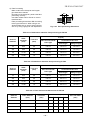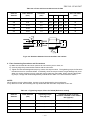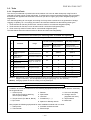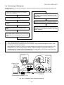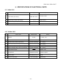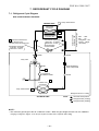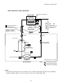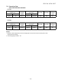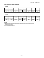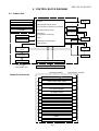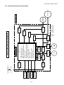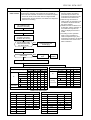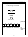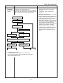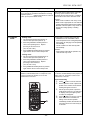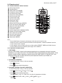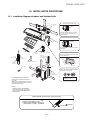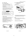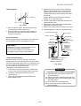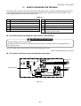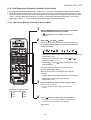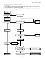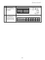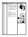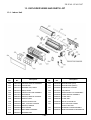
1
FILE NO. SVM-12057 SERVICE MANUAL SPLIT TYPE Indoor Unit Outdoor Unit RAS-10N3KVR-E / RAS-10N3AVR-E RAS-13N3KVR-E/ RAS-13N3AVR-E ONE-T OUCH SWING FAN FIX PU RE COM FOR SLEE T P QUIET Hi POW ER R410A October, 2012 FILE NO. SVM-12057 CONTENTS 1. SAFETY PRECAUTIONS .......................................................................... 2 2. SPECIFICATIONS ..................................................................................... 4 3. REFRIGERANT R410A ............................................................................. 8 4. CONSTRUCTION VIEWS ........................................................................ 16 5. WIRING DIAGRAM .................................................................................. 18 6. SPECIFICATIONS OF ELECTRICAL PARTS ......................................... 19 7. REFRIGERANT CYCLE DIAGRAM ........................................................ 20 8. CONTROL BLOCK DIAGRAM ................................................................ 24 9. OPERATION DESCRIPTION ................................................................... 26 10. INSTALLATION PROCEDURE ................................................................ 52 11. HOW TO DIAGNOSE THE TROUBLE ...................................................... 68 12. HOW TO REPLACE THE MAIN PARTS ................................................... 91 13. EXPLODED VIEWS AND PARTS LIST ................................................. 108 –1– FILE NO. SVM-12057 1. PRECAUTIONS FOR SAFETY For general public use Power supply cord of parts of appliance for outdoor use shall be at least polychloroprene sheathed flexible cord (design H07RN-F) or cord designation 60245 IEC66 (1.5 mm2 or more). (Shall be installed in accordance with national wiring regulations.) CAUTION New Refrigerant Air Conditioner Installation • THIS AIR CONDITIONER ADOPTS THE NEW HFC REFRIGERANT (R410A) WHICH DOES NOT DESTROY OZONE LAYER. R410A refrigerant is apt to be affected by impurities such as water, oxidizing membranes, and oils because the pressure of R410A refrigerant is approx. 1.6 times of refrigerant R22. As well as the adoption of this new refrigerant, refrigerating machine oil has also been changed. Therefore, during installation work, be sure that water, dust, former refrigerant, or refrigerating machine oil does not enter the refrigeration cycle of a new-refrigerant air conditioner. To avoid mixing refrigerant and refrigerating machine oil, the sizes of charging port connecting port connecting sections on the main unit are different from those for the conventional refrigerant, and different size tools are also required. For connecting pipes, use new and clean piping materials with highpressure withstand capabilities, designed for R410A only, and ensure that water or dust does not enter. Moreover, do not use any existing piping as its pressure withstand may be insufficient and may contain impurities. CAUTION To disconnect the appliance from the main power supply This appliance must be connected to the main power supply be means of a circuit breaker or a switch with a contact separation of at least 3 mm in all poles. The installation circuit breaker must be used specified for the power supply line of this air conditioner. DANGER • FOR USE BY QUALIFIED PERSONS ONLY. • TURN OFF MAIN POWER SUPPLY BEFORE ATTEMPTING ANY ELECTRICAL WORK. MAKE SORE ALL POWER SWITCHES ARE OFF FAILURE TO DO SO MAY CAUSE ELECTRIC SHOCK. • CONNECT THE CONNECTING CABLE CORRECTLY. IF THE CONNECTING CABLE IS CONNECTED WRONGLY, ELECTRIC PARTS MAY BE DAMAGED. • CHECK THE EARTH WIRE THAT IT IS NOT BROKEN OR DISCONNECTED BEFORE INSTALLATION. • DO NOT INSTALL NEAR CONCENTRATIONS OF COMBUSTIBLE GAS OR GAS VAPORS. FAILURE TO FOLLOW THIS INSTRUCTION CAN RESULT IN FIRE OR EXPLOSION. • TO PREVENT OVERHEATING THE INDOOR UNIT AND CAUSING A FIRE HAZARD, PLACE THE UNIT WELL AWAY (MORE THAN 2 M) FROM HEAT SOURCES SUCH AS RADIATORS, HEATERS, FURNACE, STOVES, ETC. • WHEN MOVING THE AIR CONDITIONER FOR INSTALLING IT IN ANOTHER PLACE AGAIN, BE VERY CAREFUL NOT TO GET THE SPECIFIED REFRIGERANT (R410A) WITH ANY OTHER GASEOUS BODY INTO THE REFRIGERATION CYCLE. IF AIR OR ANY OTHER GAS IS MIXED IN THE REFRIGERANT, THE GAS PRESSURE IN THE REFRIGERATION CYCLE BECOMES ABNORMALLY HIGH AND IT RESULTINGLY CAUSES BURST OF THE PIPE AND INJURIES ON PERSONS. • IN THE EVENT THAT THE REFRIGERANT GAS LEAKS OUT OF THE PIPE DURING THE INSTALLATION WORK, IMMEDIATELY LET FRESH AIR INTO THE ROOM. IF THE REFRIGERANT GAS IS HEATED BY FIRE OR SOMETHING ELSE, IT CAUSES GENERATION OF POISONOUS GAS. − 2− FILE NO. SVM-12057 WARNING • Never modify this unit by removing any of the safety guards or bypass or bypass any of the safety interlock switches. • Do not install in a place which cannot bear the weight of the unit. Personal injury and property damage can result if the unit falls. • Before doing the electrical work, attach an approved plug to the power supply cord. Also, make sure the equipment is properly earthed. • Appliance shall be installed in accordance with national wiring regulations. If you detect any damage, do not install the unit. Contact your TOSHIBA dealer immediately. • Do not use any refrigerant different from the one specified for complement or replacement. Otherwise, abnormally high pressure may by generated in the refrigeration cycle, which may result in a failure or explosion of the product or an injury to your body. CAUTION • Exposure of unit to water or other moisture before installation could reslt in electric shock. Do not store it in a wet basement or expose to rain or water. • After unpacking the unit, examine it carefully for possible damage. • Do not install in a place that can increase the vibration of the unit. Do not install in a place that can amplify the noise level of the unit or where noise and discharged air might disturb neighbors. • To avoid personal injury, be careful when handling parts with sharp edges. • Please read this installation manual carefully before installing the unit. It contains further important instructions for proper installation. • The manufacturer shall not assume any liability for the damage caused by not observing the description of this manual. − 3− FILE NO. SVM-12057 2. SPECIFICATIONS 2-1. RAS-10N3KVR-E/RAS-10N3AVR-E Unit model RAS-10N3KVR-E Indoor RAS-10N3AVR-E Outdoor Cooling capacity (kW) 2.5 Cooling capacity range (kW) 1.1 - 3.1 Heating capacity (kW) 3.2 Heating capacity range (kW) 0.9 - 4.8 Power supply Electric 1Ph/50Hz/220-240V, 1Ph/60Hz/220-230V Indoor characteristic Cooling Heating (A) 0.21 - 0.19 0.24 - 0.22 Power consumption (W) 35 40 Power factor (%) 76 76 Cooling Heating Operation mode Running current Outdoor Operation mode (A) 2.81 - 2.58 3.43 - 3.14 Power consumption Running current (W) 563 710 Power factor (%) 91 Starting current (A) COP (Cooling / Heating) Operating Indoor noise 4.18 (Cooling / Heating) (dB-A) 38/39 Medium (Cooling / Heating) (dB-A) 33/34 Low (Cooling / Heating) (dB-A) 26/28 (Cooling / Heating) (dB-A) Height (mm) Width (mm) 790 Depth (mm) 225 Net weight (kg) Fan motor output (W) Air flow rate (Cooling / Heating) (m3 / min) Width (mm) 780 Depth (mm) 290 Motor output 33 (W) 750 Single rotary type with DC-inverter variable speed control DA89X1C-23FZ2 Fan motor output (W) Air flow rate Type Indoor unit Outdoor unit Refrigerant 550 (kg) Type connection 20 8.6/9.5 (mm) Model Piping 10 Height Net weight Compressor 275 RAS-10N3AVR-E Unit model Dimention 46/47 RAS-10N3KVR-E Unit model Dimention Outdoor unit 4.18/4.27 High Outdoor Indoor unit 4.27 94 3.67 (Cooling / Heating) (m3 / min) 43 30/30 Flare connection Liquid side (mm) ∅6.35 Gas side (mm) ∅9.52 Liquid side (mm) ∅6.35 Gas side (mm) ∅9.52 Maximum length (m) 20 Maximun charge-less length (m) 15 Maximum height difference (m) Name of refrigerant Weight Wiring 10 R410A (kg) Power supply 0.8 3 Wires: Includes earth (Outdoor) connection Interconnection Usable temperature range Indoor (Cooling / Heating) (oC) 4 Wires: Includes earth 21 - 32/0-28 Outdoor (Cooling / Heating) (oC) -10-46/-15-24 * The specification may be subject to change without notice for purpose of improvement. –4– FILE NO. SVM-12057 2-2. Operation Characteristic Curve RAS-10N3KVR-E/RAS-10N3AVR-E <Cooling> <Heating> 10 9 9 8 8 7 7 6 6 Current (A) Current (A) 10 5 4 5 4 3 3 2 2 1 1 0 0 10 20 30 40 50 60 70 80 90 100 110 120 Compressor speed (rps) 0 0 10 20 30 40 50 60 70 80 90 100 110 120 Compressor speed (rps) 2-3. Capacity Variation Ratio According to Temperature RAS-10N3KVR-E/RAS-10N3AVR-E <Heating> <Cooling> 105 120 100 95 100 Heating Capacity ratio (%) Capacity ratio (%) 90 85 80 75 70 65 80 60 40 Capacity ratio 100% is 2.5kW 60 55 Capacity ratio 100% is 3.2kW Conditions Indoor:DB27℃/WB19℃ Indoor air flow:High Pipe length:5m Condition Indoor:DB20℃ Indoor air flow:High Pipe length:5m 20 50 32 33 34 35 36 37 38 39 40 41 42 43 44 45 46 Outdoor temp. (℃) 0 -15 -10 -5 0 Outdoor temp. (℃) –5– 5 10 FILE NO. SVM-12057 2-4. RAS-13N3KVR-E / RAS-13N3AVR-E Unit model RAS-13N3KVR-E / RAS-13N3AVR-E Cooling capacity Cooling capacity range Heating capacity Heating capacity range Power supply Electric Indoor characteristic Outdoor COP Operating noise Indoor unit Outdoor unit Indoor Outdoor Unit model Dimention Net weigh Fan motor output Air flow rate Unit model Dimention Net weigh Compressor Piping connection Fan motor output Air flow rate Type Indoor unit Outdoor unit (kW) (kW) (kW) (kW) Operation mode Running current Power consumption Power factor Operation mode Running current Power consumption Power factor Starting current High Medium Low (A) (W) (%) (A) (W) (%) (A) (Cooling/Heating) (Cooling/Heating) (Cooling/Heating) (Cooling/Heating) (dB-A) (dB-A) (dB-A) (dB-A) Height Width Depth (mm) (mm) (mm) (kg) (W) (Cooling/Heating) (m3 / min) Height Width Depth (mm) (mm) (mm) (kg) (W) Motor output Type Model (W) (Cooling/Heating) (m3 / min) Liquid side Gas side Liquid side Gas side (mm) (mm) (mm) (mm) (m) (m) (m) Maximum length Maximun charge-less length Maximum height difference Refrigerat Name of refrigerat Weight Wiring Power supply connection Interconnection Usable temperature range Indoor Outdoor Accessory Indoor unit Installation plate Wireless remote controller Batteries Remote controller holder Toshiba IAQ (long type) Super Sterilizer filter Mounting screw Remote controller holder Pan head wood screw Plasma air purifier Installation manual Owner's manual Outdoor unit Drain nipple Water proof rubber cap (kg) (oC) (oC) 3.5 0.8-4.1 4.2 0.9-5.6 1Ph /50Hz/220V-240V, 1Ph/60Hz/220V-230V Cooling Heating 0.21-0.19 0.24-0.22 35 40 76 76 Cooling Heating 4.57-4.20 4.93-4.52 965 1040 96 96 5.17 3.50/3.89 39/40 33/34 26/28 48/50 RAS-13N3KVR-E 275 790 225 10 20 9.5/10.4 RAS-13N3AVR-E 550 780 290 33 750 Single rotary type with DC-inverter variable speed control DA89X1C-23FZ2 43 34.0/37.5 Flare connection ∅6.35 ∅9.52 ∅6.35 ∅9.52 20 15 10 R410A 0.80 3 Wires: Includes earth (Outdoor) 4 Wires: Includes earth 21-32/0-28 -10-46/-15-24 1 1 2 1 1 6 (∅4 x 25L) 2 (∅3.1 x 16L) 1 1 1 1 2 * The specification may be subject to change without notice for purpose of improvement. –6– FILE NO. SVM-12057 <Heating> 8 8 7 7 6 6 5 5 Current (A) Current (A) 2-5. Operation Characteristic Curve RAS-13N3KVR-E / RAS-13N3AVR-E <Cooling> 4 3 2 4 3 2 Conditions Conditions o o Indoor : DB 27 C/WB 19 C o Indoor : DB 20 C Outdoor : DB 35oC Air Flow : High Pip Length : 5m Voltage : 230V 1 Outdoor : DB 7oC/WB 6oC Air Flow : High Pip Length : 5m Voltage : 230V 1 0 0 0 10 20 30 40 50 60 70 80 90 100 110 120 0 10 20 Compressor Speed (rps) 30 40 50 60 70 80 90 100 110 120 Compressor Speed (rps) 2-6. Capacity Variation Ratio According to Temperature RAS-13N3KVR-E / RAS-13N3AVR-E <Heating> <Cooling> 105 120 100 95 100 Heating Capacity ratio (%) Capacity ratio (%) 90 85 80 75 70 65 80 60 40 Capacity ratio 100% is 3500kw 60 55 Capacity ratio 100% is 4200kw Conditions Indoor:DB27℃/WB19℃ Indoor air flow:High Pipe length:5m Condition Indoor:DB20℃ Indoor air flow:High Pipe length:5m 20 50 32 33 34 35 36 37 38 39 40 41 42 43 44 45 46 Outdoor temp. (℃) 0 -15 -10 -5 0 Outdoor temp. (℃) –7– 5 10 FILE NO. SVM-12057 3. REFRIGERANT R410A This air conditioner adopts the new refrigerant HFC (R410A) which does not damage the ozone layer. The working pressure of the new refrigerant R410A is 1.6 times higher than conventional refrigerant (R22). The refrigerating oil is also changed in accordance with change of refrigerant, so be careful that water, dust, and existing refrigerant or refrigerating oil are not entered in the refrigerant cycle of the air conditioner using the new refrigerant during installation work or servicing time. The next section describes the precautions for air conditioner using the new refrigerant. Conforming to contents of the next section together with the general cautions included in this manual, perform the correct and safe work. 6. When an air conditioning system charged with a large volume of refrigerant is installed in a small room, it is necessary to exercise care so that, even when refrigerant leaks, its concentration does not exceed the marginal level. If the refrigerant gas leakage occurs and its concentration exceeds the marginal level, an oxygen starvation accident may result. 7. Be sure to carry out installation or removal according to the installation manual. Improper installation may cause refrigeration trouble, water leakage, electric shock, fire, etc. 8. Unauthorized modifications to the air conditioner may be dangerous. If a breakdown occurs please call a qualified air conditioner technician or electrician. Improper repair’s may result in water leakage, electric shock and fire, etc. 3-1. Safety During Installation/Servicing As R410A’s pressure is about 1.6 times higher than that of R22, improper installation/servicing may cause a serious trouble. By using tools and materials exclusive for R410A, it is necessary to carry out installation/servicing safely while taking the following precautions into consideration. 1. Never use refrigerant other than R410A in an air conditioner which is designed to operate with R410A. If other refrigerant than R410A is mixed, pressure in the refrigeration cycle becomes abnormally high, and it may cause personal injury, etc. by a rupture. 2. Confirm the used refrigerant name, and use tools and materials exclusive for the refrigerant R410A. The refrigerant name R410A is indicated on the visible place of the outdoor unit of the air conditioner using R410A as refrigerant. To prevent mischarging, the diameter of the service port differs from that of R22. 3. If a refrigeration gas leakage occurs during installation/servicing, be sure to ventilate fully. If the refrigerant gas comes into contact with fire, a poisonous gas may occur. 4. When installing or removing an air conditioner, do not allow air or moisture to remain in the refrigeration cycle. Otherwise, pressure in the refrigeration cycle may become abnormally high so that a rupture or personal injury may be caused. 5. After completion of installation work, check to make sure that there is no refrigeration gas leakage. If the refrigerant gas leaks into the room, coming into contact with fire in the fan-driven heater, space heater, etc., a poisonous gas may occur. 3-2. Refrigerant Piping Installation 3-2-1. Piping Materials and Joints Used For the refrigerant piping installation, copper pipes and joints are mainly used. Copper pipes and joints suitable for the refrigerant must be chosen and installed. Furthermore, it is necessary to use clean copper pipes and joints whose interior surfaces are less affected by contaminants. 1. Copper Pipes It is necessary to use seamless copper pipes which are made of either copper or copper alloy and it is desirable that the amount of residual oil is less than 40 mg/10 m. Do not use copper pipes having a collapsed, deformed or discolored portion (especially on the interior surface). Otherwise, the expansion valve or capillary tube may become blocked with contaminants. As an air conditioner using R410A incurs pressure higher than when using R22, it is necessary to choose adequate materials. Thicknesses of copper pipes used with R410A are as shown in Table 3-2-1. Never use copper pipes thinner than 0.8 mm even when it is available on the market. –8– FILE NO. SVM-12057 Table 3-2-1 Thicknesses of annealed copper pipes Thickness (mm) Nominal diameter Outer diameter (mm) R410A R22 1/4 6.35 0.80 0.80 3/8 9.52 0.80 0.80 1/2 12.70 0.80 0.80 5/8 15.88 1.00 1.00 2. Joints For copper pipes, flare joints or socket joints are used. Prior to use, be sure to remove all contaminants. a) Flare Joints Flare joints used to connect the copper pipes cannot be used for pipings whose outer diameter exceeds 20 mm. In such a case, socket joints can be used. Sizes of flare pipe ends, flare joint ends and flare nuts are as shown in Tables 3-2-3 to 3-2-6 below. b) Socket Joints Socket joints are such that they are brazed for connections, and used mainly for thick pipings whose diameter is larger than 20 mm. Thicknesses of socket joints are as shown in Table 3-2-2. Table 3-2-2 Minimum thicknesses of socket joints Nominal diameter Reference outer diameter of copper pipe jointed (mm) Minimum joint thickness (mm) 1/4 6.35 0.50 3/8 9.52 0.60 1/2 12.70 0.70 5/8 15.88 0.80 3-2-2. Processing of Piping Materials When performing the refrigerant piping installation, care should be taken to ensure that water or dust does not enter the pipe interior, that no other oil than lubricating oils used in the installed air-water heat pump is used, and that refrigerant does not leak. When using lubricating oils in the piping processing, use such lubricating oils whose water content has been removed. When stored, be sure to seal the container with an airtight cap or any other cover. 1. Flare processing procedures and precautions a) Cutting the Pipe By means of a pipe cutter, slowly cut the pipe so that it is not deformed. b) Removing Burrs and Chips If the flared section has chips or burrs, refrigerant leakage may occur. Carefully remove all burrs and clean the cut surface before installation. c) Insertion of Flare Nut –9– FILE NO. SVM-12057 d) Flare Processing Make certain that a clamp bar and copper pipe have been cleaned. By means of the clamp bar, perform the flare processing correctly. Use either a flare tool for R410A or conventional flare tool. Flare processing dimensions differ according to the type of flare tool. When using a conventional flare tool, be sure to secure “dimension A” by using a gauge for size adjustment. ØD A Fig. 3-2-1 Flare processing dimensions Table 3-2-3 Dimensions related to flare processing for R410A A (mm) Nominal diameter Outer diameter (mm) Thickness (mm) Conventional flare tool Flare tool for R410A clutch type Clutch type Wing nut type 1/4 6.35 0.8 0 to 0.5 1.0 to 1.5 1.5 to 2.0 3/8 9.52 0.8 0 to 0.5 1.0 to 1.5 1.5 to 2.0 1/2 12.70 0.8 0 to 0.5 1.0 to 1.5 2.0 to 2.5 5/8 15.88 1.0 0 to 0.5 1.0 to 1.5 2.0 to 2.5 Table 3-2-4 Dimensions related to flare processing for R22 A (mm) Nominal diameter Outer diameter (mm) Thickness (mm) Conventional flare tool Flare tool for R22 clutch type Clutch type Wing nut type 1/4 6.35 0.8 0 to 0.5 0.5 to 1.0 1.0 to 1.5 3/8 9.52 0.8 0 to 0.5 0.5 to 1.0 1.0 to 1.5 1/2 12.70 0.8 0 to 0.5 0.5 to 1.0 1.5 to 2.0 5/8 15.88 1.0 0 to 0.5 0.5 to 1.0 1.5 to 2.0 Table 3-2-5 Flare and flare nut dimensions for R410A Dimension (mm) Nominal diameter Outer diameter (mm) Thickness (mm) A B C D Flare nut width (mm) 1/4 6.35 0.8 9.1 9.2 6.5 13 17 3/8 9.52 0.8 13.2 13.5 9.7 20 22 1/2 12.70 0.8 16.6 16.0 12.9 23 26 5/8 15.88 1.0 19.7 19.0 16.0 25 29 – 10 – FILE NO. SVM-12057 Table 3-2-6 Flare and flare nut dimensions for R22 Dimension (mm) Nominal diameter Outer diameter (mm) Thickness (mm) A B C D Flare nut width (mm) 1/4 6.35 0.8 9.0 9.2 6.5 13 17 3/8 9.52 0.8 13.0 13.5 9.7 20 22 1/2 12.70 0.8 16.2 16.0 12.9 20 24 5/8 15.88 1.0 19.7 19.0 16.0 23 27 3/4 19.05 1.0 23.3 24.0 19.2 34 36 45˚ 6˚ to 4 B A C 43˚ D to 4 5˚ Fig. 3-2-2 Relations between flare nut and flare seal surface 2. Flare Connecting Procedures and Precautions a) Make sure that the flare and union portions do not have any scar or dust, etc. b) Correctly align the processed flare surface with the union axis. c) Tighten the flare with designated torque by means of a torque wrench. The tightening torque for R410A is the same as that for conventional R22. Incidentally, when the torque is weak, the gas leakage may occur. When it is strong, the flare nut may crack and may be made non-removable. When choosing the tightening torque, comply with values designated by manufacturers. Table 3-2-7 shows reference values. NOTE : When applying oil to the flare surface, be sure to use oil designated by the manufacturer. If any other oil is used, the lubricating oils may deteriorate and cause the compressor to burn out. Table 3-2-7 Tightening torque of flare for R410A [Reference values] Nominal diameter Outer diameter (mm) Tightening torque N•m (kgf•cm) Tightening torque of torque wrenches available on the market N•m (kgf•cm) 1/4 6.35 14 to 18 (140 to 180) 16 (160), 18 (180) 3/8 9.52 33 to 42 (330 to 420) 42 (420) 1/2 12.70 50 to 62 (500 to 620) 55 (550) 5/8 15.88 63 to 77 (630 to 770) 65 (650) – 11 – FILE NO. SVM-12057 3-3. Tools 3-3-1. Required Tools The service port diameter of packed valve of the outdoor unit in the air-water heat pump using R410A is changed to prevent mixing of other refrigerant. To reinforce the pressure-resisting strength, flare processing dimensions and opposite side dimension of flare nut (For Ø12.7 copper pipe) of the refrigerant piping are lengthened. The used refrigerating oil is changed, and mixing of oil may cause a trouble such as generation of sludge, clogging of capillary, etc. Accordingly, the tools to be used are classified into the following three types. 1. Tools exclusive for R410A (Those which cannot be used for conventional refrigerant (R22)) 2. Tools exclusive for R410A, but can be also used for conventional refrigerant (R22) 3. Tools commonly used for R410A and for conventional refrigerant (R22) The table below shows the tools exclusive for R410A and their interchangeability. Tools exclusive for R410A (The following tools for R410A are required.) Tools whose specifications are changed for R410A and their interchangeability R410A air-water heat pump installation No. Used tool Usage Existence of new equipment for R410A Whether conventional equipment can be used Conventional air-water heat pump installation Whether new equipment can be used with conventional refrigerant 1 Flare tool Pipe flaring Yes *(Note 1) ¡ 2 Copper pipe gauge for adjusting projection margin Flaring by conventional flare tool Yes *(Note 1) *(Note 1) 3 Torque wrench (For Ø12.7) Connection of flare nut Yes × × 4 Gauge manifold Charge hose Evacuating, refrigerant charge, run check, etc. Yes 5 × × 6 Vacuum pump adapter Vacuum evacuating Yes ¡ 7 Electronic balance for refrigerant charging Refrigerant charge Yes 8 Refrigerant cylinder Refrigerant charge Yes 9 Leakage detector Gas leakage check Yes 10 Charging cylinder Refrigerant charge (Note 2) × × × × × ¡ × ¡ × (Note 1) When flaring is carried out for R410A using the conventional flare tools, adjustment of projection margin is necessary. For this adjustment, a copper pipe gauge, etc. are necessary. (Note 2) Charging cylinder for R410A is being currently developed. General tools (Conventional tools can be used.) In addition to the above exclusive tools, the following equipments which serve also for R22 are necessary as the general tools. 1. Vacuum pump Use vacuum pump by attaching vacuum pump adapter. 2. Torque wrench (For Ø6.35, Ø9.52) 3. Pipe cutter 4. 5. 6. 7. 8. Reamer Pipe bender Level vial Screwdriver (+, –) Spanner or Monkey wrench 9. Hole core drill (Ø65) 10. Hexagon wrench (Opposite side 4mm) 11. Tape measure 12. Metal saw Also prepare the following equipments for other installation method and run check. 1. Clamp meter 2. Thermometer 3. Insulation resistance tester 4. Electroscope – 12 – FILE NO. SVM-12057 3-4. Recharging of Refrigerant When it is necessary to recharge refrigerant, charge the specified amount of new refrigerant according to the following steps. Recover the refrigerant, and check no refrigerant remains in the equipment. When the compound gauge’s pointer has indicated –0.1 Mpa (–76 cmHg), place the handle Low in the fully closed position, and turn off the vacuum pump’s power switch. Connect the charge hose to packed valve service port at the outdoor unit’s gas side. Keep the status as it is for 1 to 2 minutes, and ensure that the compound gauge’s pointer does not return. Connect the charge hose to the vacuum pump adapter. Set the refrigerant cylinder to the electronic balance, connect the connecting hose to the cylinder and the connecting port of the electronic balance, and charge liquid refrigerant. Open fully both packed valves at liquid and gas sides. (For refrigerant charging, see the figure below.) Place the handle of the gauge manifold Low in the fully opened position, and turn on the vacuum pump’s power switch. Then, evacuating the refrigerant in the cycle. 1. Never charge refrigerant exceeding the specified amount. 2. If the specified amount of refrigerant cannot be charged, charge refrigerant bit by bit in COOL mode. 3. Do not carry out additional charging. When additional charging is carried out if refrigerant leaks, the refrigerant composition changes in the refrigeration cycle, that is characteristics of the air conditioner changes, refrigerant exceeding the specified amount is charged, and working pressure in the refrigeration cycle becomes abnormally high pressure, and may cause a rupture or personal injury. (Indoor unit) (Outdoor unit) Opened Refrigerant cylinder (with siphon) Check valve Opened Opened Open/close valve for charging Closed Service port Electronic balance for refrigerant charging Fig. 3-4-1 Configuration of refrigerant charging – 13 – FILE NO. SVM-12057 1. Be sure to make setting so that liquid can be charged. 2. When using a cylinder equipped with a siphon, liquid can be charged without turning it upside down. It is necessary for charging refrigerant under condition of liquid because R410A is mixed type of refrigerant. Accordingly, when charging refrigerant from the refrigerant cylinder to the equipment, charge it turning the cylinder upside down if cylinder is not equipped with siphon. [ Cylinder with siphon ] [ Cylinder without siphon ] Gauge manifold Gauge manifold OUTDOOR unit OUTDOOR unit Refrigerant cylinder Refrigerant cylinder Electronic balance Electronic balance Siphon R410A refrigerant is HFC mixed refrigerant. Therefore, if it is charged with gas, the composition of the charged refrigerant changes and the characteristics of the equipment varies. Fig. 3-4-2 3-5. Brazing of Pipes 3-5-1. Materials for Brazing 1. Silver brazing filler Silver brazing filler is an alloy mainly composed of silver and copper. It is used to join iron, copper or copper alloy, and is relatively expensive though it excels in solderability. 2. Phosphor bronze brazing filler Phosphor bronze brazing filler is generally used to join copper or copper alloy. 1. Phosphor bronze brazing filler tends to react with sulfur and produce a fragile compound water solution, which may cause a gas leakage. Therefore, use any other type of brazing filler at a hot spring resort, etc., and coat the surface with a paint. 2. When performing brazing again at time of servicing, use the same type of brazing filler. 3-5-2. Flux 1. Reason why flux is necessary • By removing the oxide film and any foreign matter on the metal surface, it assists the flow of brazing filler. • In the brazing process, it prevents the metal surface from being oxidized. • By reducing the brazing filler’s surface tension, the brazing filler adheres better to the treated metal. 3. Low temperature brazing filler Low temperature brazing filler is generally called solder, and is an alloy of tin and lead. Since it is weak in adhesive strength, do not use it for refrigerant pipes. – 14 – FILE NO. SVM-12057 2. Characteristics required for flux • Activated temperature of flux coincides with the brazing temperature. • Due to a wide effective temperature range, flux is hard to carbonize. • It is easy to remove slag after brazing. • The corrosive action to the treated metal and brazing filler is minimum. • It excels in coating performance and is harmless to the human body. As the flux works in a complicated manner as described above, it is necessary to select an adequate type of flux according to the type and shape of treated metal, type of brazing filler and brazing method, etc. 3. Types of flux • Noncorrosive flux Generally, it is a compound of borax and boric acid. It is effective in case where the brazing temperature is higher than 800°C. • Activated flux Most of fluxes generally used for silver brazing are this type. It features an increased oxide film removing capability due to the addition of compounds such as potassium fluoride, potassium chloride and sodium fluoride to the borax-boric acid compound. 4. Piping materials for brazing and used brazing filler/flux Piping material Used brazing filler Used flux Copper - Copper Phosphor copper Do not use Copper - Iron Silver Paste flux Iron - Iron Silver Vapor flux 3-5-3. Brazing As brazing work requires sophisticated techniques, experiences based upon a theoretical knowledge, it must be performed by a person qualified. In order to prevent the oxide film from occurring in the pipe interior during brazing, it is effective to proceed with brazing while letting dry Nitrogen gas (N2) flow. Never use gas other than Nitrogen gas. 1. Brazing method to prevent oxidation 1) Attach a reducing valve and a flow-meter to the Nitrogen gas cylinder. 2) Use a copper pipe to direct the piping material, and attach a flow-meter to the cylinder. 3) Apply a seal onto the clearance between the piping material and inserted copper pipe for Nitrogen in order to prevent backflow of the Nitrogen gas. 4) When the Nitrogen gas is flowing, be sure to keep the piping end open. 5) Adjust the flow rate of Nitrogen gas so that it is lower than 0.05 m3/Hr or 0.02 MPa (0.2kgf/cm2) by means of the reducing valve. 6) After performing the steps above, keep the Nitrogen gas flowing until the pipe cools down to a certain extent (temperature at which pipes are touchable with hands). 7) Remove the flux completely after brazing. M Flow meter Stop valve Nitrogen gas cylinder 1. Do not enter flux into the refrigeration cycle. 2. When chlorine contained in the flux remains within the pipe, the lubricating oil deteriorates. Therefore, use a flux which does not contain chlorine. 3. When adding water to the flux, use water which does not contain chlorine (e.g. distilled water or ion-exchange water). 4. Remove the flux after brazing. From Nitrogen cylinder Pipe Nitrogen gas Rubber plug Fig. 3-5-1 Prevention of oxidation during brazing – 15 – FILE NO. SVM-12057 4. CONSTRUCTION VIEWS 4-1. Indoor Unit Grille Inlet Air filter Plasma purifier Air inlet 195 58 Heat exchanger Knock out system 8 8 60 52 250 Front panel 50 50 Knock out system 116 481 Installation plate hanger 172 60 55 55 60 193 58 19 149 Wireless remote controller Installation plate hanger Connecting pipe (0.35m) (For 10k,13k : Flared 9.52mm) 621 235 215 Minimum Hanger 84.5 235 215 distance 45 to ceiling Minimum Minimum distance 275 to wall 170 or more 40 40 170 or more 190 distance to wall Hanger 84.5 150 160.5 Center line – 16 – 160.5 Hanger 150 84.5 Installation plate outline 17.5 Remote controller holder Connecting pipe (0.40m) (Flared 6.35mm) 65 or more 84.5 63 Drain hose (0.50m) FILE NO. SVM-12057 4-2. Outdoor Unit A 108 28 125 80 600 50 306 86 320 320 R15 36 320 306 Ø6 hole R5.5 Ø6 hole Ø11x14 hole A detail Drawing (Back leg) Ø 25 Drain outlet FAN-GUARD 2- Ø11 x 14 Hole (For Ø8 -Ø10 anchor bolt) 36 50 R15 B Detail Drawing (Front leg) Ø 436 COVER-PV 275 550 Z 290 90 600 90 320 342 69 Electrical part cover Liquid side (Flare Ø 6.35) 137 54 92 Gas side (10,13 : Flare ∅ 9.52) Z View Service port 2 - R5-5 x 17L Ushape (For ∅ 8 - ∅ 10 anchor bolt) 600 100 or more Air intlel 320 600 or more 100 or more Air outlel 600 or more 2 - ∅11 x 14 Long holes (For ∅8 - ∅10 anchor bolt) Installation dimension – 17 – FILE NO. SVM-12057 5. WIRING DIAGRAM RAS-10N3KVR-E / RAS-10N3AVR-E RAS-13N3KVR-E / RAS-13N3AVR-E COMPRESSOR CN300 RED P04 CM 1 1 WHI P05 2 2 BLK P06 3 3 Q200~205 IGBT P.C.BOARD (MCC-5009) R221 P25 YEL Q300~305 MOS-FET R321 P23 R220 R320 R219 R319 P22 P21 BRW P20 P35 L03 YEL P34 F03 FUSE T3.15A AC250V C13 L01 PMV PULSE MOTOR VALVE 3 3 2 CN603 1 1 P18 P11 2 2 CN602 1 1 VARISTOR F01 FUSE 25A AC250V CT DB02 ORN TS (SUCTION PIPE TEMP. SENSOR) SURGE ABSORBER C14 POWER RELAY P19 P03 P01 ORN BLK RELAY P02 WHI 3 3 CN601 2 1 1 2 2 CN600 1 1 P08 Q404 P32 P33 CN701 1 P30 P31 1 2 3 L N P07 BLK 3 3 1 PUR ~ ~ ~ YEL COIL FOR 4WAY VALVE POWER SUPPLY (From Main Line) Ion Electrode GRN&YEL GRN&YEL CN01 1 (WHI) 1 3 3 CN51 Micro SW BLU BRW RED BRW BRW BRW BLK CN02 1 2 3 4 1 2 3 4 Heat exchanger 1 2 3 4 1 2 3 4 SHEET METAL Air purifier Electrode High-voltage Power Supply 3 RED BLK WHI Indoor Terminal Block 1 2 POWER SUPPLY (From outdoor Unit) 1 2 3 4 1 2 3 4 1 2 1 2 CN42 (WHI) CN41 (RED) T3.15A Fuse F01 1 1 3 3 5 5 1 1 2 2 Heat Exchanger Sensor CN62 (BLU) (TC) 1 1 2 2 Thermo Sensor CN61 (WHI) (TA) Varistor Line Filter CN31 (WHI) AC Motor 1 1 2 2 3 3 Fan Motor CN33 (WHI) WHI 1 1 YEL 2 2 YEL 3 3 YEL 4 4 YEL 5 5 1 2 3 4 5 1 2 3 4 5 Louver Mortor CN32 (WHI) 1 1 2 2 3 3 4 4 5 5 6 6 7 7 8 8 9 9 10 10 11 11 1 2 CN10 (WHI) CN11 (BLK) BLU 1 1 BLU 2 2 BLU 3 3 BLU 4 4 BLU 5 5 BLU 6 6 BLU 7 7 BLU 8 8 BLU 9 9 BLU 10 10 WHI CN22 (WHI) DC 5V DC 12V 11 11 CN21 (WHI) Main P.C Board MCC-5046 – 18 – Power Supply Circuit Wireless Unit Assembly WP-027 REACTOR 6 5 4 3 2 1 VARISTOR DB01 C12 1 1 2 2 FM FAN MOTOR 6 5 4 CN700 3 2 1 P24 YEL BLK 3 3 WHI 2 2 RED 1 1 1 2 3 4 Color indication BRW:BROWN YEL:YELLOW BLK:BLACK RED:RED BLU:BLUE WHI:WHITE GRN & YEL: GREEN & YELLOW TO (OUTDOOR TEMP. SENSOR) TD (DISCHARGE PIPE TEMP. SENSOR) TE (CONDENSER PIPE TEMP. SENSOR) COLOR IDENTIFICATION BLK:BLACK BLU:BLUE RED:RED GRY:GRAY PNK:PINK WHI:WHITE BRW:BROWN ORN:ORANGE YEL:YELLOW PUR:PURPLE FILE NO. SVM-12057 6. SPECIFICATIONS OF ELECTRICAL PARTS 6-1. Indoor Unit Part s n ame No. Type Specif icat io ns 1 Fan motor (for indoor) 2 Room temp. sensor (TA-sensor) (- ) 10kΩ at 25°C 3 Heat exchanger temp. sensor (TC-sensor) (- ) 10kΩ at 25°C 4 Louver motor AFN-220-20-4D AC240V, 20W MSBPC20F04 Output (Rated) 1W, 16 poles, DC12V Mode l na me Rating 6-2. Outdoor Unit Parts name No. 1 Reactor 2 Outdoor fan motor 3 Suction temp. sensor (TS sensor) (Inverter attached) 10k (25°C) 4 Discharge temp. sensor (TD sensor) (Inverter attached) 62k (20°C) 5 Outside air temp. sensor (TO sensor) (Inverter attached) 10k (25°C) 6 Heat exchanger temp. sensor (TE sensor) (Inverter attached) 10k (25°C) 7 Terminal block (5P) 8 Compressor DA89X1C-23FZ2 9 Coil for PMV CAM-MD12TCTH-5 10 Coil for 4-way valve CH-69 L = 19mH, 10A ICF-140-43-4R DC140V, 43W AC250V, 20A STF-01AJ646A1 – 19 − 3-phases 4-poles DC12V AC220-240V FILE NO. SVM-12057 7. REFRIGERANT CYCLE DIAGRAM 7-1. Refrigerant Cycle Diagram RAS-10N3KVR-E/RAS-10N3AVR-E INDOOR UNIT T1 Temp. measurement Indoor heat exchanger P Pressure measurement Gauge attaching port Vacuum pump connecting port TA Deoxidized copper pipe Outer dia. : 6.35mm Thickness : 0.8mm Sectional shape of heat insulator Deoxidized copper pipe Outer dia. : 9.52mm Thickness : 0.8mm Allowable pipe length Cross flow fan Allowable height difference : 10m TC Max. : 20m Min. : 2m Chargeless : 15m Charge : 20g/m (16 to 20m) Strainer Muffler 4-way valve Pulse Modulating valve at liquid side Muffler TD Compressor DA89X1C-23FZ2 Strainer TS TO Outdoor heat exchanger Temp. measurement T2 TE Refrigerant amount : 0.80kg Propeller fan OUTDOOR UNIT NOTE : Gas leak check position Refrigerant flow (Cooling) Refrigerant flow (Heating) NOTE : • The maximum pipe length of this air conditioner is 20 m. When the pipe length exceeds 15m, the additional charging of refrigerant, 20g per 1m for the part of pipe exceeded 15m is required. (Max. 100g) – 20 – FILE NO. SVM-12057 RAS-13N3KVR-E / RAS-13N3AVR-E INDOOR UNIT T1 Temp. measurement Indoor heat exchanger P Pressure measurement Gauge attaching port Vacuum pump connecting port TA Deoxidized copper pipe Outer dia. : 6.35mm Thickness : 0.8mm Sectional shape of heat insulator Deoxidized copper pipe Outer dia. : 9.52mm Thickness : 0.8mm Allowable pipe length Cross flow fan Allowable height difference : 10m TC Max. : 20m Min. : 2m Chargeless : 15m Charge : 20g/m (16 to 20m) Strainer Muffler 4-way valve Pulse Modulating valve at liquid side Muffler TD Compressor DA89X1C-23FZ2 TS TO Outdoor heat exchanger Temp. measurement T2 TE Refrigerant amount : 0.80kg Propeller fan OUTDOOR UNIT NOTE : Gas leak check position Refrigerant flow (Cooling) Refrigerant flow (Heating) NOTE : • The maximum pipe length of this air conditioner is 20 m. When the pipe length exceeds 15m, the additional charging of refrigerant, 20g per 1m for the part of pipe exceeded 15m is required. (Max. 100g) – 21 – FILE NO. SVM-12057 7-2. Operation Data RAS-10N3KVR-E/RAS-10N3AVR-E <Cooling> Tempeature Standard Heat exchanger Indoor Outdoor Compressor condition(°C) pressure pipe temp. fan mode fan mode revolution Indoor Outdoor P (MPa) T1 (°C) T2 (°C) 27/19 35/- 0.9 to 1.1 12 to 14 37 to 39 (rps) High High 49 <Heating> Tempeature Standard Heat exchanger Indoor Outdoor Compressor condition(°C) pressure pipe temp. fan mode fan mode revolution Indoor Outdoor P (MPa) T1 (°C) T2 (°C) 20/- 7/6 2.5 to 2.7 39 to 41 0 to 3 (rps) High High NOTES : 1. Measure surface temperature of heat exchanger pipe around center of heat exchaner path U bent. (Thermistor themometer) 2. Connecting piping condition : 5 m – 22 – 60 FILE NO. SVM-12057 RAS-13N3KVR-E / RAS-13N3AVR-E <Cooling> Tempeature Standard Heat exchanger Indoor Outdoor Compressor condition(°C) pressure pipe temp. fan mode fan mode revolution Indoor Outdoor P (MPa) T1 (°C) T2 (°C) 27/19 35/- 0.8 to 1.0 11 to 13 46 to 48 (rps) High High 75 <Heating> Tempeature Standard Heat exchanger Indoor Outdoor Compressor condition(°C) pressure pipe temp. fan mode fan mode revolution Indoor Outdoor P (MPa) T1 (°C) T2 (°C) 20/- 7/6 2.6 to 2.8 41 to 43 0 to 2 (rps) High High NOTES : 1. Measure surface temperature of heat exchanger pipe around center of heat exchaner path U bent. (Thermistor themometer) 2. Connecting piping condition 5 m – 23 – 80 8. CONTROL BLOCK DIAGRAM FILE NO. SVM-12057 8-1. Indoor Unit Indoor Unit Control Unit M.C.U. Heat Exchanger Sensor (Tcj) Louver Motor Functions Heat Exchanger Sensor (Tc) • Cold draft preventing Function Room Temperature Sensor (Ta) • 3-minute Delay at Restart for Compressor Infrared Rays Signal Receiver and Indication Initializing Circuit Clock Frequency Oscillator Circuit Louver Motor Drive Control • Fan Motor Starting Control Indoor Fan Motor Control • Processing (Temperature Processing) Indoor Fan Motor • Timer • Serial Signal Communication • Clean Function Power Supply Circuit Air purifier unit Converter (D.C circuit) Micro Switch Noise Filter Power Supply (From Outdoor Unit) Serial Signal Transmitter/Receiver Serial Signal Communication (Operation Command and Information) Remote Controller REMOTE CONTROLLER Operation ( ) Operation Mode Selection AUTO, COOL, DRY, HEAT Thermo. Setting Fan Speed Selection ON TIMER Setting OFF TIMER Setting Louver AUTO Swing Louver Direction Setting ECO Hi-POWER COMFORT SLEEP QUIET PURE – 24 − Infrared Rays, 36.7kHz – 25 – Heat exchanger temp.sensor Suction temp. sensor Outdoor air temp. sensor Discharge temp. sensor Noise Filter Indoor unit send/receive circuit 220–240V~ 50Hz For INDOOR UNIT Relay circuit 4-way valve P.M.V. Converter (AC → DC) Driver circuit of P.M.V. Input current sensor Clock frequency 4MHz PWM synthesis function Input current release control IGBT over-current detect control Outdoor fan control High power factor correction control Inverter output frequency control A/D converter function P.M.V. control Discharge temp. control 4-way valve control Signal communication to indoor unit High Power factor Correction circuit • • • • • • • • • • • M.C.U MCC5009 (P.C.B) Current detect Inverter (DC → AC) P.M.V. : Pulse Motor Valve M.C.U. : Micro Control Unit Inverter (DC → AC) Gate drive circuit Current detect Gate drive circuit MICRO-COMPUTER BLOCK DIAGRAM Outdoor Fan motor Compressor OUTDOOR UNIT FILE NO. SVM-12057 8-2. Outdoor Unit (Inverter Assembly) FILE NO. SVM-12057 9. OPERATION DESCRIPTION • Detection of inverter input current and current release operation • Over-current detection and prevention operation to IGBT module (Compressor stop function) • Compressor and outdoor fan stop function when serial signal is off (when the serial signal does not reach the board assembly of outdoor control by trouble of the signal system) • Transferring of operation information (Serial signal) from outdoor unit controller to indoor unit controller • Detection of outdoor temperature and operation revolution control • Defrost control in heating operation (Temp. measurement by outdoor heat exchanger and control for 4-way valve and outdoor fan) 9-1. Outline of Air Conditioner Control This air conditioner is a capacity-variable type air conditioner, which uses AC or DC motor for the indoor for motor and the outdoor fan motor. And the capacityproportional control compressor which can change the motor speed in the range from 11 to 96 rps is mounted. The DC motor drive circuit is mounted to the indoor unit. The compressor and the inverter to control fan motor are mounted to the outdoor unit. The entire air conditioner is mainly controlled by the indoor unit controller. The indoor unit controller drives the indoor fan motor based upon command sent from the remote controller, and transfers the operation command to the outdoor unit controller. The outdoor unit controller receives operation command from the indoor unit side, and controls the outdoor fan and the pulse Modulating valve. (P.M.V) Besides, detecting revolution position of the compressor motor, the outdoor unit controller controls speed of the compressor motor by controlling output voltage of the inverter and switching timing of the supply power (current transfer timing) so that motors drive according to the operation command. And then, the outdoor unit controller transfers reversely the operating status information of the outdoor unit to control the indoor unit controller. 3. Contents of operation command signal (Serial signal) from indoor unit controller to outdoor unit controller The following three types of signals are sent from the indoor unit controller. • Operation mode set on the remote controller • Compressor revolution command signal defined by indoor temperature and set temperature (Correction along with variation of room temperature and correction of indoor heat exchanger temperature are added.) • Temperature of indoor heat exchanger • For these signals ([Operation mode] and [Compressor revolution] indoor heat exchanger temperature), the outdoor unit controller monitors the input current to the inverter, and performs the followed operation within the range that current does not exceed the allowable value. As the compressor adopts four-pole brushless DC motor, the frequency of the supply power from inverter to compressor is two-times cycles of the actual number of revolution. 1. Role of indoor unit controller The indoor unit controller judges the operation commands from the remote controller and assumes the following functions. • Judgment of suction air temperature of the indoor heat exchanger by using the indoor temp. sensor. (TA sensor) • Judgment of the indoor heat exchanger temperature by using heat exchanger sensor (TC sensor) (Prevent-freezing control, etc.) • Louver motor control • Indoor fan motor operation control • LED (Light Emitting Diode) display control • Transferring of operation command signal (Serial signal) to the outdoor unit • Reception of information of operation status (Serial signal including outside temp. data) to the outdoor unit and judgment/display of error • Air purifier operation control 4. Contents of operation command signal (Serial signal) from outdoor unit controller to indoor unit controller 2. Role of outdoor unit controller The following signals are sent from the outdoor unit controller. • The current operation mode • The current compressor revolution • Outdoor temperature • Existence of protective circuit operation For transferring of these signals, the indoor unit controller monitors the contents of signals, and judges existence of trouble occurrence. Contents of judgment are described below. • Whether distinction of the current operation status meets to the operation command signal • Whether protective circuit operates When no signal is received from the outdoor unit controller, it is assumed as a trouble. Receiving the operation command signal (Serial signal) from the indoor unit controller, the outdoor unit performs its role. • Compressor operation control • Operation control of outdoor fan motor Operations followed to judgment of serial signal from indoor side. • P.M.V. control • 4-way valve control – 26 – FILE NO. SVM-12057 9-2. Operation Description 1. Basic operation ........................................................................................................... 28 1. Operation control ................................................................................................... 28 2. Cooling/Heating operation ..................................................................................... 29 3. AUTO operation ..................................................................................................... 29 4. DRY operation ........................................................................................................ 29 2. Indoor fan motor control ............................................................................................. 30 3. Outdoor fan motor control ........................................................................................... 32 4. Capacity control .......................................................................................................... 33 5. Current release control ............................................................................................... 33 6. Release protective control by temperature of indoor heat exchanger ........................ 34 7. Defrost control (Only in heating operation) ................................................................ 35 8. Louver control ............................................................................................................. 36 1) Louver position ....................................................................................................... 36 2) Air direction adjustment ......................................................................................... 36 3) Swing ..................................................................................................................... 36 9. ECO operation ............................................................................................................ 37 10. Temporary operation ................................................................................................... 38 11. Air purifying control [Detection of abnormality] .......................................................... 39 12. Discharge temperature control ................................................................................... 39 13. Pulse Modulating valve (P.M.V.) control ..................................................................... 40 14. Self-Cleaning function ................................................................................................ 42 15. Remote-A or B selection ............................................................................................ 44 16. QUIET mode ............................................................................................................. 45 17. COMFORT SLEEP mode ............ ............................................................................. 45 18. Short Timer ................................................................................................................ 45 19. One-Touch Comfort .................................................................................................. 46 20. Hi-POWER Mode ...................................................................................................... 46 21. FILTER Indicator ............................................................................................... 46 9-3. Auto Restart Function ................................................................................................ 47 9-3-1. How to Set the Auto Restart Function .............................. ........................................ 47 9-3-2. How to Cancel the Auto Restart Function ................................................................ 48 9-3-3. Power Failure During Timer Operation ................................................................... 48 9-4. Remote Controller and Its Fuctions ..................................................................... 49 9-4-1. Parts Name of Remote Controller .............................................................................. 49 9-4-2. Operation of remote control ...................................................................................... 49 9-4-3. Name and Functions of Indications on Remote Controller ....................................... 52 – 27 − FILE NO. SVM-12057 Item Operation flow and applicable data, etc. 1. Basic operation Description 1. Operation control Receiving the user’s operation condition setup, the operation statuses of indoor/outdoor units are controlled. 1) The operation conditions are selected by the remote controller as shown in the below. 2) A signal is sent by ON button of the remote controller. 3) The signal is received by a sensor of the indoor unit and processed by the indoor controllers as shown in the below. 4) The indoor controller controls the indoor fan motor and louver motor. 5) The indoor controller sends the operation command to the outdoor controller, and sends/receives the control status with a serial signal. 6) The outdoor controller controls the operation as shown in the left, and also controls the compressor, outdoor fan motor, 4-way valve and pulse Modulating valve. Remote controller Selection of operation conditions ON/OFF Control contents of remote controller • ON/OFF (Air conditioner/Air purifier) • Operation select (COOL/HEAT/AUTO/DRY) • Temperature setup • Air direction • Swing • Air volume select (AUTO/LOW/LOW+/MED/MED+/HIGH) • ECO • COMFORT SLEEP • QUIET • ON timer setup • PRESET • OFF timer setup • ONE-TOUCH • Hi-POWER Indoor unit Signal receiving Indoor unit control Operation command Serial signal send/receive Indoor unit control • Command signal generating function of indoor unit operation • Calculation function (temperature calculation) • Activation compensation function of indoor fan • Cold draft preventive function • Timer function • Indoor heat exchanger release control ~ Outdoor unit Serial signal send/receive Outdoor unit control Outdoor unit control • Frequency control of inverter output • Waveform composite function • Calculation function (Temperature calculation) • AD conversion function • Quick heating function • Delay function of compressor reactivation • Current release function • GTr over-current preventive function • Defrost operation function – 28 – • Indoor fan motor • Louver motor Inverter • Compressor • Outdoor fan motor • 4-way valve • Pulse Modulating valve (P.M.V.) FILE NO. SVM-12057 Item 1. Basic operation Operation flow and applicable data, etc. Description 2. Cooling/Heating operation The operations are performed in the following parts by controls according to cooling/heating conditions. 1) Receiving the operation ON signal of the remote controller, the cooling or heating operation signal starts being transferred form the indoor controller to the outdoor unit. 2) At the indoor unit side, the indoor fan is operated according to the contents of “2. Indoor fan motor control” and the louver according to the contents of “9. Louver control”, respectively. 3) The outdoor unit controls the outdoor fan motor, compressor, pulse Modulating valve and 4-way valve according to the operation signal sent from the indoor unit. Operation ON Indoor unit control Setup of remote controller Indoor fan motor control / Louver control / Operation Hz Control (Requierment) Sending of operation command signal Outdoor unit control Compressor revolution control / Outdoor fan motor control / Operation Hz control (Include limit control) 4-way valve control In cooling operation: ON In heating operation: OFF Pulse Modulating valve control [ 3. AUTO operation Selection of operation mode As shown in the following figure, the operation starts by selecting automatically the status of room temperature (Ta) when starting AUTO operation. *1. When reselecting the operation mode, the fan speed is controlled by the previous operation mode. Ta Cooling operation Ts + 1 Monitoring (Fan) Ts – 1 Heating operation ] 1) Detects the room temperature (Ta) when the operation started. 2) Selects an operation mode from Ta in the left figure. 3) Fan operation continues until an operation mode is selected. 4) When AUTO operation has started within 2 hours after heating operation stopped and if the room temperature is 20°C or more, the fan operation is performed with ”Super Ultra LOW” mode for 3 minutes. Then, select an operation mode. 5) In AUTO mode, either cooling or heating operation will be selected. When room temperature reach set temperature commpressor will stop. In case that the compressor stops for 15 minutes, the AUTO mode will reselect cooling or heating operation. 4. DRY operation 1) Detects the room temperature (Ta) when the DRY operation started. DRY operation is performed according to the difference between room temperature and the setup temperature as 2) Starts operation under conditions in the shown below. left figure according to the temperature difference between the room temperaIn DRY operation, fan speed is controlled in order to ture and the setup temperature (Tsc). prevent lowering of the room temperature and to avoid air Setup temperature (Tsc) flow from blowing directly to persons. = Set temperature on remote controller [˚C] (Ts) + (0.0 to 1.0) Ta L– (W5) 3) When the room temperature is lower 1°C or less than the setup temperature, turn off the compressor. +1.0 (W5+W3) / 2 +0.5 SUL (W3) Tsc Fan speed − 29 − FILE NO. SVM-12057 Item Operation flow and applicable data, etc. 2. Indoor fan motor control Description <In cooling operation> (This operation controls the fan speed at indoor unit side.) The indoor fan (cross flow fan) is operated by the phasecontrol induction motor. The fan rotates in 5 stages in MANUAL mode, and in 5 stages in AUTO mode, respectively. (Table 1) COOL ON Fan speed setup MANUAL (Fig. 1) Fan speed Indication AUTO L W6 L+ (L + M) / 2 M W9 M+ (M + H) / 2 H WC Quiet L− Air volume AUTO Ta [˚C] M+(WB) +2.0 a *3 *3 : Fan speed = (M + –L) x 3/4 + L +1.5 b *4 *4 : Fan speed = (M + –L) x 2/4 + L +1.0 c *5 *5 : Fan speed = (M + –L) x 1/4 + L +0.5 d Tsc e L(W6) * The values of fan speed and air flow volume indicate on the table are measured when the louver is inclined downward. Fan speed and air flow volume broadly vary with position of louver. (Fig. 2) +2.5 * Symbols : Ultra High : High : Medium+ : Medium : Low+ : Low : Low– : Ultra Low : Super Ultra Low UH H M+ M L+ L LUL SUL 1) When setting the fan speed to L, L+, M, M+,H or Quiet on the remote controller, the operation is performed with the constant speed shown in Fig. 1. 2) When setting the fan speed to AUTO on the remote controller, revolution of the fan motor is controlled to the fan speed level shown in Fig. 2 and Table 1 according to the setup temperature, room temperature, and heat exchanger temperature. (Linear approximation from M+ and L) (Table 1) Indoor fan air flow rate RAS-10N3KVR-E Fan speed level COOL HEAT DRY Fan speed RAS-13N3KVR-E Air flow rate Fan speed Air flow rate (rpm) (m3/h) (rpm) (m3/h) WF UH 1210 571 1300 620 WE H 1210 571 1300 620 UH 1170 546 1250 590 H 1120 515 1200 570 M+ 1040 465 1080 490 M 1000 440 1050 465 L+ 960 415 990 434 L 870 359 870 359 L+ 850 347 860 353 L 760 291 770 297 L- 760 291 770 297 WD UH WC H WB M+ M+ M+ WA W9 M W8 W7 L+ W6 L W5 L- LUL W4 UL UL 700 253 720 266 W3 SUL SUL 650 222 670 234 500 129 520 141 500 129 500 129 W2 W1 SUL – 30 – FILE NO. SVM-12057 Item Operation flow and applicable data, etc. 2. Indoor fan motor control Description <In heating operation> 1) When setting the fan speed to L, L+, M, M+, H or Quiet on the remote controller, the operation is performed with the constant speed shown in Fig. 3 and Table 1. 2) When setting the fan speed to AUTO on the remote controller, revolution of the fan motor is controlled to the fan speed level shown in Fig. 5 according to the set temperature and room temperature. 3) Min air flow rate is controlled by temperature of the indoor heat exchanger (Tc) as shown in Fig. 4. 4) Cold draft prevention, the fan speed is controlled by temperature of the indoor heat exchanger (Tc) as shown in Fig. 6. 5) In order to prevent Cold draft when compressor step during heating operation. Then louver will move to upper position and fan speed will reduce or off. HEAT ON Fan speed setup MANUAL (Fig. 3) Indication AUTO Fan speed L W8 L+ (L + M) / 2 M WB M+ (M + H) / 2 H WE YES TC ≥ 42˚C Min air flow rate control NO Limited to Min WD tap Tc 52 51 * 42 41 (Fig. 4) No limit * Fan speed = (TC – – W8) + W8 Cold draft preventive control Basic fan control Fan speed AUTO TA [˚C] TSC –0.5 –1.0 –1.5 –2.0 –2.5 b L+ (W9) 46 45 Tc 46 45 34 33 33 32 33 32 21 20 *A+4 *A+4 *A+4 *A-4 *A-4 *A-4 H (WE) c d *1 e *2 Line-approximate H and SUL with Tc. SUL (W2) f *3 Stop g –5.0 Fan speed MANUAL in starting Fan speed AUTO in stability Fan speed AUTO in starting M+ (WD) –5.5 H (WE) *1: Fan speed = (M + -L+) x 1 4 + L+ *2: Fan speed = (M + -L+) x 2 4 + L+ *3: Fan speed = (M + -L+) x 3 4 + L+ (Calculated with linear approximation from M+ and L+) * No limitation while fan speed MANUAL mode is in stability. * A: When Tsc ≥ 24, A is 24, and when Tsc < 24, A is Tsc Tsc: Set value (Fig. 5) (Fig. 6) [In starting and in stability] In starting FAN AUTO In stability • Until 12 minutes passed after operation start • When 12 to 25 minutes passed after operation start and room temp. is higher than (set temp. –3°C) • When 12 to 25 minutes passed after operation start and room temp. is 3°C or lower than set temp. • When 25 minutes or more passed after operation start • Room temp. ≥ Set temp. –3.5°C FAN Manual • Room temp. < Set temp. –4°C – 31 – FILE NO. SVM-12057 Item 3. Outdoor fan motor control Operation flow and applicable data, etc. Description The blowing air volume at the outdoor unit side is controlled. Receiving the operation command from the controller of indoor unit, the controller of outdoor unit controls fan speed. * For the fan motor, a DC motor with non-stage variable speed system is used. However, it is limited to 8 stages for reasons of controlling. 1) The operation command sent from the remote controller is processed by the indoor unit controller and transferred to the controller of the outdoor unit. 2) When strong wind blows at outdoor side, the operation of air conditioner continues with the fan motor stopped. 3) Whether the fan is locked or not is detected, and the operation of air conditioner stops and an alarm is displayed if the fan is locked. 4) According to each operation mode, by the conditions of outdoor temperature (To) and compressor revolution, the speed of the outdoor fan shown in the table is selected. Air conditioner ON (Remote controller) Indoor unit controller 1) Outdoor unit operation command (Outdoor fan control) 2) Fan speed ≥ 400. when the motor OFF. (by strong wind) NO YES Fan motor OFF continues (Use wind for heat exchanging) YES Air conditioner OFF Fan motor ON 3) Fan lock NO Alarm display 4) Motor operates as shown in the table below. In cooling operation Compressor speed (rps) To During ECO mode ~ 13.8 In Heating operation ~ 31.7 32.3 ~ MAX MIN MAX MIN MAX MIN MAX To > 38°C To > 28°C f2 f3 fC fD fE fF f2 f3 fA fC fD fF To > 15°C To > 5.5°C f2 f3 f7 fA f9 fC f1 f3 f2 f5 f4 To > 0°C f1 f1 f1 f2 f2 To < 15°C f3 f9 fA To < 5.5°C f8 fA fD To < −5.0°C To > 15°C fB fC fD f7 f3 f3 f6 f4 To < 15°C f3 f3 f8 To < 5.5°C f5 f9 f9 To < −5.5°C f7 fA fB fA fB fD To < 0°C f0 f0 f0 f1 f1 f2 To > 38°C f2 f3 fB fC fC fD To < 38°C f2 f3 f2 f3 fB fC fF fD fF When To is abnormal fD fF fD Compressor speed (rps) ~16.8 ~47.9 48.5 ~ MAX To > 15°C f3 f8 f9 To During ECO mode When To is abnormal Outdoor fan speed (rpm) RAS-10N3AVR-E RAS-13N3AVR-E Tap Tap Tap 0 f9 600 Tap f0 0 f9 650 f0 f1 200 fA 700 f1 200 fA 600 f2 300 fB 700 f2 300 fB 650 f3 370 fC 800 f3 370 fC 700 f4 440 fD 800 f4 440 fD 700 f5 440 fE 800 f5 440 fE 700 f6 500 fF 800 f6 500 fF 700 f7 f8 550 600 f7 f8 550 600 – 32 – FILE NO. SVM-12057 Item 4. Capacity control Operation flow and applicable data, etc. Description The cooling or heating capacity depending on the load is adjusted. According to difference between the setup value of temperature and the room temperature, the capacity is adjusted by the compressor revolution. 1) The difference between set temperature on remote controller (Ts) and room temperature (Ta) is calculated. 2) According to the temperature difference, the correction value of Hz signal which determines the compressor speed is set up. 3) The rotating position and speed of the motor are detected by the electromotive force occurred on the motor winding with operation of the compressor. 4) According to the difference resulted from comparison of the correction value of Hz signal with the present operation Hz, the inverter output and the commutation timing are varied. 5) Change the compressor motor speed by outputting power to the compressor. * The contents of control operation are same in cooling operation and heating operation Remote contr oller Indoor unit Set temp. (Ts) Room temp. (Ta) Ts −Ta Correction value of Hz signal Detection of electromotive force of compressor motor winding Detection of motor speed (Operation Hz) and rotor position Correction value of Hz signal- Operating Hz Inverter output change Commutation timing change Change of compressor speed 5. Current release This function prevents troubles on the electronic parts of the control compressor driving inverter. This function also controls drive circuit of the compressor speed so that electric power of the compressor drive circuit does not exceed the specified value. Outdoor temp. To Outdoor unit inverter main circuit control current Setup of current release point Operating current ≤ Setup value High Reduce compressor speed Low Current decrease Capacity control continues. Cooling current release value Outdoor temp. RAS-10N3KVR-E 4.27A 4.27A 44ºC 6.75A 6.75A 39ºC 15.5ºC 8.47A 8.47A 45ºC 40ºC 16ºC 11ºC RAS-13N3KVR-E 10.5ºC – 33 – 1) The input current of the outdoor unit is detected in the inverter section of the outdoor unit. 2) According to the detected outdoor temperature, the specifice value of the current is selected. 3) Whether the current value exceeds the specifice value or not is judged. 4) If the current value exceeds the specified value, this function reduces the compressor speed and controls speed up to the closest one commanded from the indoor unit within the range which does not exceed the specified value. Heating current release value RAS-10N3KVR-E 6.30A RAS-13N3KVR-E 6.30A 6.30A 6.30A 6.30A 6.30A FILE NO. SVM-12057 Item Operation flow and applicable data, etc. Indoor heat exchanger temperature 6. Release protective <In cooling/dry operation> control by tempera- (Prevent-freezing control for indoor heat exchanger) ture of indoor heat In cooling/dry operation, the sensor of indoor heat exchanger exchanger detects evaporation temperature and controls the compressor speed so that temperature of the heat exchanger does not exceed the specified value. Usual cooling capacity control R When the value is in Q zone, the compressor speed is kept. 7˚C Q 6˚C 1) When temperature of the indoor heat exchanger drops below 5°C, the compressor speed is reduced. (P zone) 2) When temperature of the indoor heat exchanger rises in the range from 6°C to under 7°C, the compressor speed is kept. (Q zone) 3) When temperature of the indoor heat exchanger rises to 7°C or higher, the capacity control operation returns to the usual control in cooling operation. (R zone) P 5˚C Reduction of compressor speed <In heating operation> (Prevent-overpressure control for refrigerating cycle) In heating operation, the sensor of indoor heat exchanger detects condensation temperature and controls the compressor speed so that temperature of the heat exchanger does not exceed the specified value. Indoor heat exchanger temperature Description Reduction of compressor speed P 55˚C 52˚C Q When the value is in Q zone, the compressor speed is kept. 48˚C R Usual heating capacity control – 34 – 1) When temperature of the indoor heat exchanger rises in the range from 52°C to 55°C, the compressor speed is kept. (Q zone) When temperature of the indoor heat exchanger drops in the range from 48°C to under 55°C, the compressor speed is kept. (Q zone) 2) When temperature of the indoor heat exchanger rises to 55°C or higher, the compressor speed is reduced. (P zone) 3) When temperature of the indoor heat exchanger does not rise to 52°C, or when it drops below to 48°C, the capacity control operation returns to the usual control in heating operation. (R zone) FILE NO. SVM-12057 Item Operation flow and applicable data, etc. 7. Defrost control (This function removes frost adhered to the outdoor (Only in heating heat exchanger.) operation) The temperature sensor of the outdoor heat exchanger (Te sensor) judges the frosting status of the outdoor heat exchanger and the defrost operation is performed with 4-way valve reverse defrost system. Outdoor heat exchanger temperature Start of heating operation 0’ 10’ 15’ 27’40” 34’ Operation time (Minute) –5˚C C zone –7˚C A zone –20˚C B zone * * The minimum value of Te sensor 10 to 15 minutes after start of operation is stored in memory as Te0. Table 1 A zone When Te0 - TE ≥ 2.5 continued for 2 minutes in A zone, defrost operation starts. B zone When the operation continued for 2 minutes in B zone, defrost operation starts. C zone When Te0 - TE ≥ 3 continued for 2 minutes in C zone, defrost operation starts. – 35 – Description The necessity of defrost operation is detected by the outdoor heat exchanger temperature. The conditions to detect the necessity of defrost operation differ in A, B, or C zone each. (Table 1) <Defrost operation> • Defrost operation in A to C zones 1) Stop operation of the compressor for 20 seconds. 2) Invert (ON) 4-way valve 10 seconds after stop of the compressor. 3) The outdoor fan stops at the same time when the compressor stops. 4) When temperature of the indoor heat exchanger becomes 38°C or lower, stop the indoor fan. <Finish of defrost operation> • Returning conditions from defrost operation to heating operation 1) Temperature of outdoor heat exchanger rises to +8°C or higher. 2) Temperature of outdoor heat exchanger is kept at +5°C or higher for 80 seconds. 3) Defrost operation continues for 15 minutes. <Returning from defrost operation> 1) Stop operation of the compressor for approx. 50 seconds. 2) Invert (OFF) 4-way valve approx. 40 seconds after stop of the compressor. 3) The outdoor fan starts rotating at the same time when the compressor starts. FILE NO. SVM-12057 Item Operation flow and applicable data, etc. Description 8. Louver control This function controls the air direction of the indoor unit. 1) Louver • The position is automatically controlled according to the operation position mode (COOL/HEAT). • The set louver position is stored in memory by the microcomputer, and the louver returns to the stored position when the next operation is performed. (Cooling/Heating memory position) The angle of the louver is indicated as the louver closes fully is 0°. 1) Louver position in cooling operation Initial setting of "Cooling storage position" Louver : Directs downward (35.3°) 2) Louver position in heating operation Heating operation/ AUTO (HEAT) Initial setting of “Heating storage position” Louver : Directs downward (80.5˚) • The louver position can be arbitrarily set up by pressing [FIX] button. 2) Air direction adjustment Air direction Horizontal blowing 3) Swing Inclined blowing Blowing downward Inclined blowing Horizontal blowing • Swing operation is perfor in range 35° with the Fixed position as the center. • If the swing range exceeded either upper or lower limit position, swing operation is perfomed in range 35° from the limit. – 36 – • Swing When pressing [SWING] button during operation, the louver starts swinging. FILE NO. SVM-12057 Item 9. ECO operation Operation flow and applicable data, etc. Description When pressing [ECO] button on the remote controller, a Economic operation is performed. <Cooling operation> 1) The control target temperature increase 0.5ºC per hour up to 2ºC starting from the set temperature when ECONO has been received. <Cooling operation> This function operates the air conditioner with the difference between the set and the room temperature as shown in the following figure. Zone Frequency 6.0 5.5 5.0 4.5 4.0 3.5 3.0 2.5 2.0 1.5 1.0 *9 *8 Min Hz 1 0.5 Dry Max *12 *11 *10 TSC -0.5 -1.0 -2.0 FAN 3) The compressor speed is controlled as shown in the left figure. during the ECO operation. 12 11 10 9 8 7 6 5 4 3 2 The indoor fan speed is not controlled and can be selected (Room temp. – Set temp.) °C 6.5 2) The indoor fan speed is depend on presetting and can change every speed after setting ECO operation. OFF 1H 2H 3H 4H Time * 12 (DRY max - COOL min) /6 x 5 + COOL min * 11 (DRY max - COOL min) /6 x 4 + COOL min * 10 (DRY max - COOL min) /6 x 3 + COOL min * 9 (DRY max - COOL min) /6 x 2 + COOL min * 8 (DRY max - COOL min) /6 x 1 + COOL min Hz RAS-10N3KVR-E RAS-13N3KVR-E Cool min 20 20 DRY max 35 37 < Heating Operation > → Time Compressor speed 0Hz (Room temp. – Set temp.) 30 minutes 0 –0.5 –1.0 –1.5 –2.0 –2.5 –3.0 –4.0 –5.0 –6.0 –7.0 –8.0 –9.0 –10.0 –11.0 A B A A zone aHz <Heating operation> 1) The difference of room temperature and set temperature are separated in to A zone, B zone and C zone. Three zone will changed again 30 minutes after ECO operation start. 2) The compressor speed is controlled as shown on the table. C B zone a to cHz B C zone cHz C Hz a 20 b 50 – 37 – 3) The indoor fan speed is not controlled and can be selected during the ECO operation. FILE NO. SVM-12057 Item Operation flow and applicable data, etc. Description 10. Temporary Pressing [RESET] button starts the temporary operaoperation tion of [AUTO] operation. When keeping [RESET] button pressed for 10 seconds or more, the temporary [COOL] operation is performed. YES Filter lamp ON Press RESET button. NO NO Did you press [RESET] button for 3 seconds or more? Temporary [AUTO] operation YES YES Did you press [RESET] button for 10 seconds or more? 1) When pressing [RESET] button, the temporary [AUTO] operation starts. 2) When keeping [RESET] button pressed for 3 seconds or more, Pi, Pi, Pi sound is heard and [AUTO RESTART] control is changed. 3) When keeping [RESET] button pressed for 10 seconds or more, “Pi” sound is heard and the temporary [COOL] operation starts. 4) If the filter lamp goes on, press [RESET] button to go off the filter lamp, and then press [RESET] button again. 5) To stop the temporary operation, press the button again. NO Switch to [AUTO RESTART] control. 11. Air purifying control Temporary [COOL] Operation This function generates nagative ion while cleaning the air in the room. If air purifier-ON signal is received while the air conditioner stops, the air purifier starts operation, and if it is received while the air conditioner operates, the air conditioner and the air purifier start operation. The air ion generator operates linked with the air purifying operation. Operation button Present status PURE button Air conditioner Air purifier AC operation* Air purifier only Stop (All) AC + Air purifier Air conditioner AC + Air purifier All stop AC operation All stop Stop Joint use of AC and air purifier Air purifying operation Louver*1 Fan speed *2 Cooling position AUTO, L, L+, M, M+, H * When the previous operation was the operation of air conditioner + air purifier, an operation of air conditioner + air purifier starts by pushing AC button on the remote controller. (Operation of air conditioner + air purifier is stored in memory.) *1 Swing is available *2 Fan speed is Fan Auto mode varies in order, (M + 1) → (L) → (L–) → (SL). AC + Air purifying operation Follows to AC operation Follows to AC operation Sending air purifier-ON 1 1 , 2 Sending air purifier-OFF 2 3 Air conditioner stops Air conditioner operates Operation lamp ON Start of air purifier-ON *1 Memory position of louver/COOL Air conditioner + air purifier operate Air purifier operates , 4 4 Air conditioner + Air purifier operate Operation lamp OFF Filter-OFF Fan stop Air conditioner operates *2 Fan ON Air purifier-OFF Air purifier ON Louver close Air purifying operation All stop – 38 – 3 FILE NO. SVM-12057 Item Operation flow and applicable data, etc. 1. Purpose The air purifying control function is to alert the user to trouble in the ionizing or air purifying operation. 11. Air purifying control [Detection of abnormality] Purifying operation YES 2. Description Trouble is determined to have occurred (indicated by the FILTER indicator) in the following four cases. 1) When a count of 1000H has been reached on the timer 2) When the panel switch has been set to OFF by the opening of the air inlet grile, etc. 3) When an abnormal discharge caused by a symptom such as the build-up of dirt has been detected while the air purifier is ON 4) When the electric dust collector has not been installed correctly * Trouble case (2) or (3) is deemed to have occurred when the action concerned continues for more than one second. Total operation time 1000H NO Purifier power ON NO Error input YES Purifier power ON 1 minute or less NO Filter lamp-OFF continues. YES Filter lamp ON Purifier power OFF Purifier power OFF Purifier power ON after 10 minutes from the error input. Filter lamp ON Error input 5 times NO YES Purifier power OFF Purifier power OFF 1 2 1 2 Reset by RESET button. Reset by RESET button or by the stop direction from the remote controller. * When the breaker is turned [ON] (In restart time after power failure) or RESET button is pressed while the FILTER indicator is turned on, the air purifier is not turned on until the integrated operation time of the indoor fan exceeds 1 hour after operation start (It is nor the air purifier operation time). It is the safety measures considering an incomplete drain when electric dust collector has been cleaned with water. 12. Discharge temperature control Td value 117°C 112°C 108°C 105°C 98°C Description Control operation Judges as an error and stops the compressor. Reduce the compressor speed. Reduce slowly compressor speed. Keeps the compressor speed. If the operation is performed with lower speed than one commanded by the serial signal, speed is slowly raised up to the commanded speed. Operates with speed commanded by the serial signal. – 39 – 3. Operation The sequence that FILTER indicator is turned on are described in the left flowchart. 1) When 1000H timer counts up, the FILTER indicator keeps lighting even if the operation is stopped by the remote controller. The timer is stored in memory of the microcomputer, and the operation time is cleared by filter RESET button on the indoor unit or a power failure. (FILTER indicator goes off.) 2) A trouble detected within 1 minute after activation of the air is immediately judged as an error and the FILTER indicator goes on. 3) In case that 1 minute passed after activation of the purifier, the purifier is turned off while the PURE indicator keeps ON. After 10 minutes passed, restart the purifier and an error is judged again. 1. Purpose This function detects error on the refrigerating cycle or error on the compressor, and performs protective control. 2. Operation • Control of the compressor speed The speed control is performed as described in the left table based upon the discharge temperature. FILE NO. SVM-12057 Item Operation flow and applicable data, etc. Description 13. Pulse Modulating valve (P.M.V.) control This function controls throttle amount of the refrigerant in the refrigerating cycle. According to operating status of the air conditioner, this function also controls the open degree of valve with an expansion valve with pulse Modulation. 1) When starting the operation, move the valve once until it fits to the stopper. (Initialize) * In this time, “Click” sound may be heard. 2) Adjust the open degree of valve by super heat amount. (SH control) 3) If the discharge temperature was excessively up, adjust the open degree of valve so that it is in the range of set temperature. (Discharge temp. control) Starting up 4) When defrost operation is performed, the open degree of valve is adjusted according to each setup conditions during preparation for defrost and during defrost operation (4-way valve is inversed.). 5) When operation is OFF by the remote controller or when compressor is OFF by room temperature control, the open degree of valve is adjusted to the stop position. Initialize Move to initial position Compressor ON SH control Td release control PMV open degree control Stop by remote controller Power OFF Room temp. sensor (Ta sensor) control Defrost * SH (Super Heat amount) = Ts (Temperature of suction pipe of the compressor) – Tc or Te (Heat exchanger temperature at evaporation side) * PMV: Pulse Modulating Valve – 40 – FILE NO. SVM-12057 Item Description Operation flow and applicable data, etc. 14. Self-Cleaning function Unit now performing cooling or dry operation Press “STOP” button Only timer indicator lights, and Self Cleaning operation starts 1. Purpose The Self-Cleaning operation is to minimize the growth of mold, bacteria etc. by running the fan and drying so as to keep the inside of the air conditioner clean. Self-Cleaning operation When the cooling or dry operation shuts down, the unit automatically starts the SelfCleaning operation which is then performed for the specified period based on duration of the operation which was performed prior to the shutdown, after which the Self-Cleaning operation stops. (The Self-Cleaning operation is not performed after a heating operation.) 2. Operation 1) When the stop signal from the remote controller or timer-off function is received, only the timer indicator light. 2) The period of the Self-Cleaning operation is determined by the duration of the operation performed prior to the reception of the stop code. 3) After the Self-Cleaning operation has been performed for the specified period, the unit stops operating. Time set now elapses Operation stops • During Self-Cleaning operations: The louver opens slightly. The indoor fan operates continuously at a speed of 500 rpm. Self-Cleaning operation times Operation time Cooling: Auto (cooling) Dry Self-Cleaning operation time Up to 10 minutes No Self-Cleaning operation performed (0 minutes) 10 minutes or longer 30 mins. Heating: Auto (heating) Auto (fan only) No Self-Cleaning operation performed Shutdown • To stop an ongoing Self-Cleaning operation at any time Press the start/stop button on the remote controller twice during the Self-Cleaning operation. (After pressing the button for the first time, press it for the second time without delay (within 10 minutes).) – 41 – FILE NO. SVM-12057 Item 14. Self-Cleaning function Operation flow and applicable data, etc. Description • Self-Cleaning diagram Operation display ON OFF OFF FCU fan ON rpm is depend on presetting. ON (500RPM) OFF FCU louver OPEN OPEN (12.7º) CLOSE Timer display ON or OFF depend on presetting of timer function. ON ON or OFF depend on presetting of timer function. Compressor ON or OFF depend on presetting per room temperature. OFF OFF ON or OFF depend on presetting per room temperature. OFF OFF Cool mode or dry mode operation more than 10 mins. Self-Cleaning mode operate 30 mins. CDU fan Operation time Turn off by remote controller or timer-off function. Automatically turn-off. How to Set or Cancel Self-Cleaning operation. (Default setting from factory is ON) 1. Connect jumper lead at J201 of the indoor P.C. board assembly. 2. To cancel Self-Cleaning operation. Turn the power supply ON Press the [RESET] button located on the front panel of the indoor unit for more than 3 seconds. After 3 seconds, the unit beeps three times. The Self-Cleaning is cancelled. 3. To set Self-Cleaning operation. Turn the power supply ON Press the [RESET] button located on the front panel of the indoor unit for more than 3 seconds. After 3 seconds, the unit beeps three times and the indicator blinks for 5 seconds. The Self-Cleaning is set. − 42 − One J201 is added, it will effect as following. The operation when press the RESET button for 3 seconds will be changed from Set/Cancel the AUTO-RESTART to Set/Cancel the Self-Cleaning. AUTO-RESTART function will not activate. In case of AUTO-RESTART is need, disconnect the jumper J201 and set it again after Set/Cancel the Self-Cleaning finished. Note : J201 is near the MCU, so so take steps to ensure that it will not be exposed to excessive of heat. Also take care to avoid solder bridging with the surrounding components. FILE NO. SVM-12057 Item Operation flow and applicable data, etc. Description J201 PCB NO : MCC-5046 15. Remote Setting the remote controller Controller-A or To separate using of remote controller for each indoor B selection unit in case of 2 air conditioner are installed nearly. Remote Control B Setup. 1. Press [RESET] button on the indoor unit to turn the air conditioner ON. 2. Point the remote control at the indoor unit. 3. Push and hold [CHECK] button on the Remote Control by the tip of the pencil. "00" will be shown on the display (Picture 1 ). 4. Press [MODE] during pushing [CHECK]. "B" will show on the display and "00" will disappear and the air conditioner will turn OFF. The Remote Control B is memorized [Picture 2 ). Control to be A. 2. Remote Control A has not "A" display. 3. Default setting of Remote Control from factory is A. 2 − 43 − 2. Description When operating one indoor unit in a situation where two indoor units have been installed in the same room or nearby rooms, this operation prevents the remote controller signal from being received simultaneously by both units, thus preventing both units from operating. 3. Operation The indoor unit on which the remote controller selection has been set to B receives the signal of the remote controller also set to B. (At the factory the remote controller selection is set to A on all the indoor units. There is no A setting display.) NOTE : 1. Repeat above step to reset Remote 1 1. Purpose This operation is to operate only one indoor unit using one remote controller. FILE NO. SVM-12057 Item 16. QUIET mode Description Operation flow and applicable data, etc. When the [QUIET] selected form [Fan] button, the fan of the indoor unit will be restricted the revolving speed at speed L − until the [Fan] button is selected other speed (cancel Quiet mode). Quiet mode is the system which, control the revolving speed of indoor fan to work constantly at lower than speed L. In addition, noise level of indoor unit is less than usual. Remarks : 1. Quiet mode is unable to work in dry mode. 2. Quiet mode is appropriate to work with less cooling load and less heating load condition. Because of the fan speed L- may cause not enough the cooling capacity or heating capacity. 17. COMFORT SLEEP Cooling mode • The preset temperature will increase as show on ECO operation (Item No. 9) • Press the [COMFORT SLEEP] button to choose the operating hours. Repeat pressing to select the hours. (1hr, 3hr, 5hr or 9hr) • If the [COMFORT SLEEP] button is pressed again means cancel comfort sleep mode. The principles of comfort sleep mode are: • Quietness for more comfortable. When room temperature reach setting temperature • Save energy by changing room temperature automatically. • The air condition can shut down by itself automatically. Remarks: 1. Comfort sleep mode will not operate in dry mode and fan only mode. Heating mode • The preset temperature will drop down as show on ECO operation (Item No. 9) • Press the [COMFORT SLEEP] button to choose the operating hours. Repeat pressing to setect thehours. (1hr, 3hr, 5hr or 9 hr) • If the [COMFORT SLEEP] button is pressed again means cancel comfort sleep mode. 18. Short Timer In the normal condition, after switching one circuit breaker, 3-minute delay time for compressor and 1 hour for plasma air purifier are set for the maintenance of the unit. Purpose To start the unit immediately for the purpose of testing, trial...etc, short timer can be used. maintenance of the unit. Short Timer Setting j k Press [ ] button to turn the unit OFF. Set the operation mode or plasma air purifier on the remote control without sending the signal to the unit. l Use the tip of the pencil to push the [CHK] button and hold, "00" will show on display, them press [SET] button to make "00" disappear. Press [ ] button to turn the unit ON. When short timer is activated, all setting on the remote operates immediately, besides, all indicatiors on front panel turns ON continuously for 3 seconds. 2 SWING ONE-TOUCH PURE FIX FA N QUIET m n Hi POWER COMFORT SLEEP 1 − 44 − FILE NO. SVM-12057 Item 19. One-Touch Comfort Operation flow and applicable data, etc. One touch comfort is the fully automated operation that is set according to the preferable condition in a region. 0 * AUTO/L 12 L 25 Operation condition for model to Europe market When an indoor unit receives "One Touch Comfort Signal" from the remote controller, the indoor unit operates as following. 1) Air conditioner starts to operation when the signal is received, even if the air conditioner was OFF. Fan Operation AUTO Description Time after operation starts (min) *AUTO/L: Fan operates depends on the setting temperature and room temperature. 2) Operation mode is set according to room temperature, the same as AUTO mode. 3) Target temperature is 24ºC. 4) Louver position is set as stored position of the operating mode. 5) Fan is controlled as followings. During the One Touch Comfort mode if the indoor unit receives any signal with other operation mode, the unit will cancel the comfort mode and operates according to the signal received. 20. Hi-POWER Mode ([Hi-POWER] button on the remote controller is pressed) ∗ The Hi-POWER operation will be cancelled when press [Hi-POWER] button again. When [Hi-POWER] button is pressed while the indoor unit is in Auto, Cooling or Heating operation, HiPOWER mark is indicated on the display of the remote controller and the unit operates as follows. 1. Automatic operation • The indoor unit operates in according to the current operation. 2. Cooling operation • The preset temperature drops 1ºC (The value of the preset temperature on the remote controller does not change.) The indoor unit's fan speed level increase 1 tap 3. Heating operation • The preset temperature increases 2ºC (The value of the preset temperature on the remote controller does not change.) The indoor unit's fan speed level increase 1 tap 4. The Hi-POWER mode can not be set in Dry operation 21. FILTER Indicator When the elapsed time reaches 1000 hours after air purifier operation, the FILTER indicator lights. After cleaning the filters, turn off the FILTER indicator. How to Turn Off FILTER Indicator Press [RESET] button on the indoor unit. NOTE : If [RESET] button is pushed while the FILTER indicator is not lit, the indoor unit will start the automatic operation. − 45 − . FILE NO. SVM-12057 9-3. Auto Restart Function This indoor unit is equipped with an automatic restarting function which allows the unit to restart operating with the set operating conditions in the event of a power supply being accidentally shut down. The operation will resume without warning three minutes after power is restored. This function is not set to work when shipped from the factory. Therefore it is necessary to set it to work. 9-3-1. How to Set the Auto Restart Function To set the auto restart function, proceed as follows: The power supply to the unit must be on; the function will not set if the power is off. Push the [RESET] button located in the center of the front panel continuously for three seconds. The unit receives the signal and beeps three times. The unit then restarts operating automatically in the event of power supply being accidentally shut down. • When the unit is stand-by (Not operating) Motions Operation Push [RESET] button for more than three seconds. (Less than 10 seconds) The unit is on standby. ↓ The unit starts to operate. ↓ PURE The green indicator is on. After approx. three seconds, The unit beeps three times and continues to operate. The green indicator flashes for 5 seconds. If the unit is not required to operate at this time, push [RESET] button once more or use the remote controller to turn it off. • When the unit is in operation Operation Push [RESET] button for more than three seconds. (Less than 10 seconds) Motions The unit is in operation. The green indicator is on. ↓ The unit stops operating. ↓ The green indicator is turned off. After approx. three seconds, The unit beeps three times. PURE The green indicator flashes for 5 seconds. If the unit is required to operate at this time, push [RESET] button once more or use the remote controller to turn it on. • While the filter check indicator is on, the RESET button has the function of filter reset button. – 46 – FILE NO. SVM-12057 9-3-2. How to Cancel the Auto Restart Function To cancel auto restart function, proceed as follows : Repeat the setting procedure : the unit receives the signal and beeps three times. The unit will be required to be turned on with the remote controller after the main power supply is turned off. • When the system is on stand-by (not operating) Operation Push [RESET] button for more than three seconds. (Less than 10 seconds) Motions The unit is on standby. ↓ The unit starts to operate. ↓ The green indicator is on. After approx. three seconds, The unit beeps three times and continues to operate. PURE If the unit is not required to operate at this time, push [RESET] button once more or use the remote controller to turn it off. • When the system is operating Operation Push [RESET] button for more than three seconds. (Less than 10 seconds) Motions The unit is in operation. The green indicator is on. ↓ The unit stops operating. ↓ The green indicator is turned off. After approx. three seconds, The unit beeps three times. PURE If the unit is required to operate at this time, push [RESET] button once more or use the remote controller to turn it on. 9-3-3. Power Failure during Timer Operation When the unit is turned off because of power failure during timer operation, the timer operation is cancelled. In that case, set the timer operation again. NOTE : The Daily Timer is reset while a command signal can be received from the remote controller even if it stopped due to a power failure. – 47 – FILE NO. SVM-12057 9-4. Remote control 9-4-1. Remote Controller and Its Functions 1 2 3 4 5 6 7 8 9 10 11 12 13 14 15 16 17 18 19 20 21 22 1 Infrared signal emitter Start/Stop button Mode select button (MODE) Temperature button (TEMP) Fan speed button (FAN) Swing louver button (SWING) Set louver button (FIX) On timer button (ON) Off timer button (OFF) Setup button (SET) Clear button (CLR) Memory and Preset button (PRESET) One-Touch button (ONE-TOUCH) High power button (Hi-POWER) Economy button (ECO) Quiet button (QUIET) Comfort sleep button (COMFORT SLEEP) Plasma Air Purifier button (PURE) Filter reset button (FILTER) Set clock button (CLOCK) Check button (CHECK) Reset button (RESET) 12 4 2 3 7 13 18 15 8 17 21 20 S WING ONE-TOUCH P UR E F IX FAN 6 5 QUIE T 16 Hi POWER 14 C OMFOR T S LE E P 11 9 10 22 19 Note: • The provided Remote Controller is a wireless type, which also can be used as a wire. Please see “How to Connect The Remote Controller for Wired Operation", located in installation instruction, in case of wired control is required. • In wire operation, remote controller will return to initial condition (PRESET, TIMER and CLOCK will return to initial condition) when user shutdown power supply of Air conditioner. 9-4-2. Operation of remote control 1. ONE-TOUCH Press the "ONE-TOUCH" button for fully automated operation that is customised to the typical consumer preferences in your region of the world. The coutomised settings control temperature air flow strength, air flow direction and other settings to provide you alternate contact with "ONE-TOUCH" OF THE BUTTON. If you prefer other settings you can select from the many other operation functions of your Toshiba unit Press ONE-TOUCH : Start the operaton. 2. AUTOMATIC OPERATION To automatically select cooling, or fan only operation. 1. Press MODE : Select A. 2. Press : Set the desired temperature. 3. COOLING / HEATING / FAN ONLY OPERATION To automatically select cooling, or fan only operation. 1. Press MODE : Select Cool 2. Press , Heat , or Fan only . : Set the desired temperature. Cooling / Heating : Min 17°C - Max 30°C, Fan Only: No temperature indication 3. Press HIGH FAN : Select AUTO, LOW , LOW+ , MED . – 48 – , MED+ , or FILE NO. SVM-12057 4. DRY OPERATION (COOLING ONLY) For dehumidification, a moderate cooling performance is controlled automatically. 1. Press 2. Press : Select Dry MODE . : Set the desired temperature. 5. AIR PURIFYING OPERATION During air conditioner operation Press PURE to start and air ionizer operation. The plasma air purifier and air ionizer can be activated or deactivated during air conditioner is stopped and the air ionizer starts in conjunction with plasma air purifier operation. Note: The FILTER indicator (orange) turns on after PURE operation is performed for about 1000 hours. 6. Hi-POWER OPERATION To automatically control room temperature and airflow for faster cooling or heating operation (except in DRY and FAN ONLY mode) Press Hi POWER : Start and stop the operation. 7. ECO OPERATION To automatically control room to save energy (except in DRY and FAN ONLY mode) Press : Start and stop the operation. Note: Cooling operation; the set temperature will increase automatically 0.5 degree/ hour for 4 hours (maximum 2 degrees increase). For heating operation the set temperature will decrease. 8. TEMPORARY OPERATION In case of the misplaced or discharged remote control • Pressing the RESET button, the unit can start or stop without using the remote control. • Operation mode is set on AUTOMATIC operation, preset temperature is 24°C and fan operation is automatic speed. 9. TIMER OPERATION Setting the ON Timer Setting the OFF Timer 1 Press : Set the desired ON timer. Press : Set the desired OFF timer. 2 Press : Set the timer. Press : Set the timer. 3 Press : Cancel the timer. Press Daily timer allows the user to set both the ON & OFF timers and will be activated on a daily basis. Setting Daily Timer 1 Press : Set the ON timer. 3 Press 2 Press : Set the OFF timer. 4 Press button during the ( or ) mark flashing. . · During the daily timer is activation, both arrows ( or )are indicated. – 49 – FILE NO. SVM-12057 Note: · Keep the remote control in accessible transmission to the indoor unit; otherwise, the time lag of up to 15 minutes will occur. · The setting will be saved for the next same operation. 10. PRESET OPERATION Set your preferred operation for future use. The setting will be memorized by the unit for future operation (except air flow direction). 1. Select your preferred operation. 2. Press and hold for 3 seconds to memorize the setting. The P mark displays. 3. Press : Operate the preset operation. 11. AUTO RESTART OPERATION To automatically restart the conditioner after the power failure (Power of the unit must be on.) Setting 1. Press and hold the RESET button on the indoor unit for 3 seconds to set the operation. (3 beep sound and OPERATION lamp blink 5 time/sec for 5 seconds) • Do not operate ON timer and OFF timer. 2. Press and hold the RESET button on the indoor unit for 3 seconds to cancel the operation. (3 beep sound but OPERATION lamp does not blink) 12. QUIET OPERATION To operate at super low fan speed for quiet operation (except in DRY mode) Press QUIET : Start and stop the operation. Note: Under certain conditions, QUIET operation may not provide adequate cooling due to low sound features. 13. COMFORT SLEEP OPERATION To save energy while sleeping, automatically control air flow and automatically turn OFF. Press : Select 1, 3, 5 or 9 hrs for OFF timer operation. Note: The cooling operation, the set temperature will increase automatically 0.5 degree/hour for 4 hours (maximum 2 degrees increase). – 50 – FILE NO. SVM-12057 9-4-3. Name and Functions of Indications on Remote Controller [Display] All indications, except for the clock time indicator, are displayed by pressing the 1 2 3 4 5 6 Transmission mark This transmission mark indicates when the remote controller transmits signals to the indoor unit. Mode indicator Indicates the current operation mode. (AUTO : Automatic control, A : Auto changeover : Cool, : Dry, : Heat) control, 7 Temperature indicator Indicates the temperature setting. (17°C to 30°C) 8 PURE indicator Shows that the electrical air purifying operation is in progress. FAN speed indicator Indicates the selected fan speed. 9 AUTO or five fan speed levels (LOW , LOW+ , MED , MED+ HIGH ) can be shown. , Indicates AUTO when the operating mode is : Dry. either AUTO or 10 button. TIMER and clock time indicator The time setting for timer operation or the clock time is indicated. The current time is always indicated except during TIMER operation. Hi-POWER indicator Indicates when the Hi-POWER operation starts. Press the Hi-POWER button to start and press it again to stop the operation. (PRESET) indicator Flashes for 3 seconds when the PRESET button is pressed during operation. mark is shown when holding down the The button for more than 3 seconds while the mark is flashing. Press another button to turn off the mark. ECO indicator Indicates when the ECO is in activated. Press the ECO button to start and press it again to stop operation. A, B change indicator remote controller When the remote controller switching function is set, “B” appears in the remote controller display. (When the remote controller setting is “A”, there is no indication at this position.) 11 Comfort sleep Indicates when comfort sleep is activaled. Press comfort sleep button to selectter 11 10 1 13 12 Quiet 2 Indicates when quiet is activated. Press quiet button to start and press it again to stop operation. 14 13 One-Touch Indicates when one touch comfort is activated. Press one-touch button to start the operation. 14 Swing Indicates when louver is swing. Press swing button to start the swing operation and press it again to stop the swing operation. 12 4 7 9 3 8 5 6 – 51 – FILE NO. SVM-12057 10. INSTALLATION PROCEDURE 170 mm 65 mm or more 10-1. Installation Diagram of Indoor and Outdoor Units or m ore Hoo For the rear left and left piping Hook 1 170 k Installation plate mm or m ore Air filt tac ot he fro nt pa ne l.) Make sure to run the drain hose sloped downward. 8 5 Filter ( Cut the piping hole sloped slightly. Shield pipe ht 6 Filter Battery cover Insert the cushion between the indoor unit and wall, and tilt the indoor unit for better operation. Do not allow the drain hose to get slack. er (At Wall Flat head wood screw 4 Remote control holder The auxiliary piping can be connected to the left, rear left, rear right, right, bottom right or bottom left. Vinyl tape Apply after carrying out a drainage test. 8 Flat head wood screw 2 Flat head wood screw 3 Batteries 600 mm or more Right & Wireless remote control 100 mm or Rear right Bottom right ore 100 or m mm Left Bottom left Saddle mo Insulate the refrigerant pipes separately with insulation, not together. re Extension drain hose (Not available, provided by installer) ore rm 600 Rear left o mm 600 mm or m ore The provided Remote Controller is a wireless type, which also can be used as a wire. Please see "How to Connect The Remote Controller for Wired Operation", in case of wired control is required. 6 mm thick heat resisting polyethylene foam Remark : Detail of accessory and installation parts can see in the accessory sheet. • Some pictures might be different from the actual parts. • Before installing the wireless remote controller 2 Wireless remote controller • Loading Batteries 1. Remove the battery cover. 2. Insert 2 new batteries (AAA type) following the (+) and (- ) positions. – 52 – 3 Batteries FILE NO. SVM-12057 10-2. Installation 10-2-1. Optional installation parts Part Code Parts name Q'ty A Refrigerant piping Liquid side : ∅6.35 mm Gas side : ∅9.52 mm B Pipe insulating material (polyethylene foam, 6 mm thick) C Putty, PVC tapes One each 1 One each Fixing bolt arrangement of outdoor unit 108 mm 125 mm Air inlet 25 m m 28 mm 102 mm 86 mm 320 mm Æ Air outlet 90 mm 600 mm Drain outlet Fig. 10-2-1 · Secure the outdoor unit with fixing bolts and nuts if the unit is likely to be exposed to a strong wind. · Use ∅ 8 mm or ∅ 10 mm anchor bolts and nuts. · If it is necessary to drain the defrost water, attach drain nipple 9 and cap water proof 10 to the bottom plate of the outdoor unit before installing it. – 53 − FILE NO. SVM-12057 10-2-2. Accessory and installation parts Part No. Part name (Q’ty) Part No. Part name (Q’ty) 5 1 6 Wireless remote control x 1 3 10 7 Remote control holder x 1 Others Cap water proof* x 2 11 Flat head wood screw ∅3.1 x 25 s x 1 Mounting screw ∅4 x 25 s x 6 8 4 Drain nipple* x 1 Plasma air purifier x 1 Battery x 2 Part name (Q’ty) 9 TOSHIBA New IAQ filter (L) x 1 Installation plate x 1 2 Part No. 12 Flat head wood screw ∅3.1 x 16 s x 2 Battery-cover x 1 The part marked with asterisk (*) is packaged with the outdoor unit. Name Owner’s manual Installation manual – 54 – FILE NO. SVM-12057 10-2-3. Installation/Servicing Tools Changes in the product and components In the case of an air conditioner using R410A, in order to prevent any other refrigerant from being charged accidentally, the service port diameter of the outdoor unit control valve (3 way valve) has been changed. (1/2 UNF 20 threads per inch) • In order to increase the pressure resisting strength of the refrigerant piping flare processing diameter and size of opposite side of flare nuts has been changed. (for copper pipes with nominal dimensions 1/2 and 5/8) New tools for R410A New tools for R410A Applicable to R22 model Changes Gauge manifold × As pressure is high, it is impossible to measure by means of conventional gauge. In order to prevent any other refrigerant from being charged, each port diameter has been changed. Charge hose × In order to increase pressure resisting strength, hose materials and port size have been changed (to 1/2 UNF 20 threads per inch). When purchasing a charge hose, be sure to confirm the port size. Electronic balance for refrigerant charging ¡ As pressure is high and gasification speed is fast, it is difficult to read the indicated value by means of charging cylinder, as air bubbles occur. Torque wrench (nominal diam. 1/2, 5/8) × The size of opposite sides of flare nuts have been increased. Incidentally, a common wrench is used for nominal diameters 1/4 and 3/8. ¡ By increasing the clamp bar’s receiving hole, strength of spring in the tool has been improved. Flare tool (clutch type) Gauge for projection adjustment — — Used when flare is made by using conventional flare tool. Vacuum pump adapter ¡ Connected to conventional vacuum pump. It is necessary to use an adapter to prevent vacuum pump oil from flowing back to the charge hose. The charge hose connecting part has two ports-one for conventional refrigerant (7/16 UNF 20 threads per inch) and one for R410A. If the vacuum pump oil (mineral) mixes with R410A a sludge may occur and damage the equipment. Gas leakage detector × Exclusive for HFC refrigerant. • Incidentally, the “refrigerant cylinder” comes with the refrigerant designation (R410A) and protector coating in the U. S’s ARI specified rose color (ARI color code: PMS 507). • Also, the “charge port and packing for refrigerant cylinder” require 1/2 UNF 20 threads per inch corresponding to the charge hose’s port size. – 55 – FILE NO. SVM-12057 10-3-2. Cutting a Hole and Mounting Installation Plate 10-3. Indoor Unit 10-3-1. Installation Place • A place which provides the spaces around the indoor unit as shown in the diagram. • A place where there are no obstacle near the air inlet and outlet. • A place which allows easy installation of the piping to the outdoor unit. • A place which allows the front panel to be opened. • The indoor unit shall be installed as top of the indoor unit comes to at least 2 m height. Also, it must be avoided to put anything on the top of the indoor unit. <Cutting a hole> When installing the refrigerant pipes from the rear. Pipe hole ∅65 mm CAUTION 100 mm • Direct sunlight on the indoor unit wireless receiver should be avoided. • The microprocessor in the indoor unit should not be too close to RF sources. (For details, see the owner's manual.) Fig. 10-3-2 1. After determining the pipe hole position on the mounting plate (A), drill the pipe hole (∅ 65 mm) at a slight downward slant to the outdoor side. <Remote control> • A place where there are no obstacles such as curtain that may block the signal from the indoor unit . • Do not install the remote control in a place exposed to direct sunlight or close to a heating source, such as a stove. • Keep the remote control at least 1 m apart from the nearest TV set or stereo equipment. (This is necessary to prevent image disturbances or noise interference.) • The location of the remote control should be determined as shown below. NOTE : • When drilling a wall that contains a metal lath, wire lath or metal plate, be sure to use a pipe hole brim ring sold separately. <Mounting the installation plate> Anchor bolt holes 62 (Side view) 82.5 2 m or more from floor Indoor unit Hook (Top view) Indoor unit 170 85 Reception range Remote controller 1 Reception range Pipe hole Remote controller Hook Indoor unit Hook Thread Pipe hole Weight 7 Fig. 10-3-3 Fig. 10-3-1 – 56 – Mounting screw Installation plate FILE NO. SVM-12057 <When the installation plate is directly mounted on the wall> 10-3-3. Wiring Connection 1. Securely fit the installation plate onto the wall by screwing it in the upper and lower parts to hook up the indoor unit. 2. To mount the installation plate on a concrete wall with anchor bolts. use the anchor bolt holes as illustrated in the below figure. 3. Install the installation plate horizontally in the wall. CAUTION When installing the installation plate with mounting screw, do not use the anchor bolt holes. Otherwise the unit may fall down and result in personal injury and property damage. Installation plate (Keep horizontal direction.) <How to connect the connecting cable> Wiring of the connecting cable can be carried out without removing the front panel. 1. Remove the air inlet grille. Open the air inlet grille upward and pull it toward you. 2. Remove the terminal cover and cord clamp. 3. Insert the connecting cable (according to the local cords) into the pipe hole on the wall. 4. Take out the connecting cable through the cable slot on the rear panel so that it protrudes from the front show on the figure below. 5. Insert the connecting cable fully into the terminal block and secure it tightly with screws. 6. Tighten firmly but not over 1.2 N.m (0.12 kgf.m) 7. Secure the connecting cable with the cord clamp. 8. Fix the terminal cover, rear plate bushing and air inlet grille on the indoor unit. CAUTION Anchor bolt Projection 15 mm or less • Be sure to refer to the wiring system diagram labeled inside the front panel. • Check local electrical cords and also any specific wiring instructions or limitations. 5 mm dia. hole 7 Mounting screw ∅4 x 25 s Terminal block Clip anchor (local parts) Terminal cover Cord clamp Screw Fig. 10-3-4 Screw 100 mm Connecting cable Earth line 10 mm 3 abo ut 2 CAUTION 0c m 45 mm 90 mm Stripping length of the connecting cable Failure to firmly install the unit may result in personal injury and property damage if the unit falls. NOTE : • In case of block, brick, concrete or similar type walls, make 5 mm dia. holes in the wall. • Insert clip anchors for appropriate mounting screws 7. • Use stranded wire only. • Wire type : More than H07RN-F or 60245 IEC66 (1.0 mm2 or more.) NOTE : • Secure four corners and lower parts of the installation plate with 4 to 6 mounting screws to install it. – 57 – FILE NO. SVM-12057 <How to connect remote controller for wire operation> 70 mm 4 * Wire size 28-22AWG or 0.08-0.32 mm2 Outer diameter not over 4.7 mm, control wire length 30 m. or less. Indoor unit 5 mm Notch for wire out Control wire 5 6 Remote controller Fig. 10-3-6 Tighten firmly Terminal but not over Control wire 0.12 N·m (0.01 kgf·m) Control wire For indoor unit Fig. 10-3-8 1. Open the air inlet grille upward. 2. Securely remove two screws at the front panel. 3. Slightly open the iower part of the front panel thon pull the upper part of the front toward you to remove it from the rear plate as shown on figure 1 . 4. After removing the front panel, remove the display unit and open the cover as shown on figure 2 and 3 . 5. Arrange the control wire as detail and specification as shown on figure 4 . 6. Securely connect the control wire to terminal of display unit board as shown on figure 5 (tighten firmly but not over : 0.12 N·m (0.01 kgf·m). 7. Set the control wire throughout at slot on front cover of display unit then reassembly display with main casing by reverse process of figure 2 and 3 . Make sure the control wire must not be pressed by front and rear cover of display unit. 8. Set the control wire out from indoor unit same portion as power supply and connecting cable as shown on figure 6 . 9. Reassembly the indoor unit by reverse process of 1 to 3. Air inlet grille For remote controller 1. Remove cover of remote controller by sliding down and take it out. 2. If batteries are exist, please take them out. The combination of using wire controller and batteries may cause of batteries explosion. 3. Make hole for insert control wire by use screwdriver break the polyester sheet as shown on figure 7 . 4. Insert control wire from rear side of remote controller as shown on figure 8 . 5. Fix control wire which arrange as shown on figure 9 and 10 to terminal by provided screws (tighten firmly but not over : 0.25 N·m (0.03 kgf·m). 6. Set control wire through gutter way at rear side of remote controller as shown on figure 11 . 7. Fix provided screw (∅ 3.1 x 16L) on the wall to hang remote controller as shown on figure 12 . 8. Mark and arrange hole for fix below screw (∅ 3.1 x 25L) as shown on figure 12 . 9. Assembly battery cover which provided with accessory bag then use provide screw (∅ 3.1 x 25L) to fix battery cover together with wall as shown on figure 13 (tighten firmly but not over 0.15 N.m (0.02 kgf.m)). 10. Reassembly cover of remote controller. 1 7 Front panel 2 8 Polyester sheet close hole for insert control wire 1 3 Control wire 30 mm 2 ! 9 3 10 mm * Wire size 28-22 AWG (0.08~0.32 mm2) Outer diameter not over 4.7 mm, control wire length 30 m. or less. Display board Display unit Fig. 10-3-7 Fig. 10-3-9 – 58 – Control wire Terminal Tighten firmly but not over 0.25 N·m (0.03 kgf·m) FILE NO. SVM-12057 Control wire Rear left Bottom left Remote controller Left Wall Bottom right Remote controller Right Screw (∅3.1 x 25L) for fi x battery cover " # Screw Battery cover Tighten fi rmly but not over 0.15 N·m (0.02 kgf·m) $ Fig. 10-3-10 Die-cutting Front panel slit Hole for hang remote controller Piping preparation Screw (∅3.1 x 16L) for hang remote controller Changing drain hose Rear right Control wire 1. Die-cutting front panel slit Cut out the slit on the left or right side of the front panal for the left or right connection and the slit on the bonttom left or right side of the front panel for the bottom left or right connection with a pair of nippers. 2. Changing drain hose For leftward connection, bottom leftward connection and rear leftward connection’s piping, it is necessary to change the drain hose and drain cap. How to remove the drains cap Clip drain cap by needle-nose plier, and pull out. *Remark : 1. Recommend to use double insulation lead wire for connect remote control and air conditioner. 2. For wire operation, 1 remote control can control only 1 indoor unit. 3. In wire operation, remote controller will return to initial Fig. 10-3-11 condition (PRESET, TIMER and CLOCK will return to initial condition) when user shutdown power supply How to install the drain hose of air conditioner. Firmly insert drain hose connecting part until hitting on <How to install the air inlet grille on the indoor unit> a heat insulator and fix it with a screw. • When attaching the air inlet grille, the contrary of the How to remove the drain hose removed operation is performed. • The drain hose can be removed by removing the screw securing the drain hose and then pulling out the drain hose. • When removing the drain hose, be careful of any sharp edges of steel plate. The edges can injuries. • To install the drain hose, insert the drain hose firmly until the connection part contacts with heat insulator, 10-3-4. Piping and drain hose installation and the secure it with original screw. Heat insulator <Piping and drain hose forming> * Since dewing results in a machine trouble, make sure to insulate both the connecting pipes. (Use polyethylene foam as insulating material.) Fig. 10-3-12 Drain hose – 59 – CAU FILE NO. SVM-12057 <Left-hand connection with piping> How to fix the drains cap 1) Insert hexagonal wrench (4 mm) in a center head. Bend the connecting pipe so that it is laid within 43 mm above the wall surface. If the connecting pipe is laid exceeding 43 mm above the wall surface, the indoor unit may unstably be set on the wall. When bending the connecting pipe, make sure to use a spring bender so as not to crush the pipe. 4 mm Bend the connection pipe within a radius of 30 mm. To connect the pipe after installation of the unit (figure) (To the forefront of flare) Fig. 10-13-13 270 mm 2) Firmly insert drains cap. 230 mm Gas side Liquid side No gap Insert a hexagon wrench (4 mm) Outward form of indoor unit 43 mm Do not apply lubricating oil (refrigerant machine oil) when inserting the drain cap. Application causes deterioration and drain leakage of the plug. 80 Fig. 10-13-14 CAUTION Use the handle of screwdriver, etc. Fig. 10-3-17 CAUTION Firmly insert the drain hose and drain cap; otherwise, water may leak. <In case of right or left piping> R 30 mm (Use polisin (polyethylene) core or the like for bending pipe.) After scribing slits of the front panel with a knife or a making-off pin, cut them with a pair of nippers or an equivalent tool. CAUTION NOTE If the pipe is bent incorrectly, the indoor unit may unstably be set on the wall. After passing the connecting pipe through the pipe hole, connect the connecting pipe to the auxiliary pipes and wrap the facing tape around them. CAUTION • Bind the auxiliary pipes (two) and connecting cable with facing tape tightly. In case of leftward piping and rear-leftward piping, bind the auxiliary pipes (two) only with facing tape. Indoor unit Slit Auxiliary pipes Fig. 10-13-15 <In case of bottom right or bottom left piping> Installation plate After scribing slits of the front panel with a knife or a making-off pin, cut them with a pair of nippers or an equivalent tool. Slit Fig. 10-13-16 Connecting cable • Carefully arrange pipes so that any pipe does not stick out of the rear plate of the indoor unit. • Carefully connect the auxiliary pipes and connecting pipes to each other and cut off the insulating tape wound on the connecting pipe to avoid double-taping at the joint, moreover, seal the joint with the vinyl tape, etc. • Since dewing results in a machine trouble, make sure to insulate both the connecting pipes. (Use polyethylene foam as insulating material.) • When bending a pipe, carefully do it, not to crush it. – 60 – FILE NO. SVM-12057 10-3-5. Indoor unit fixing 10-3-6. Drainage 1. Pass the pipe through the hole in the wall, and hook the indoor unit on the installation plate at the upper hooks. 2. Swing the indoor unit to right and left to confirm that it is firmly hooked up on the installation plate. 3. While pressing the indoor unit onto the wall, hook it at the lower part on the installation plate. Pull the indoor unit toward you to confirm that it is firmly hooked up on the installation plate. 1. Run the drain hose sloped downwards. NOTE • The hole should be made at a slight downward slant on the outdoor side. Do not form the drain hose into a wavy shape. Do not rise the drain hose. 50 mm or more Hook here 1 1 Installation plate Do not put the drain hose end into water. 2 Hook Press (unhook) Fig. 10-3-20 Fig. 10-3-18 Do not put the drain hose end in the drainage ditch. For detaching the indoor unit from the installation plate, pull the indoor unit toward you while pushing its bottom up at the specified parts. 2. Put water in the drain pan and make sure that the water is drained out of doors. 3. When connecting extension drain hose, insulate the connecting part of extension drain hose with shield pipe. Shield pipe Drain hose Push Inside the room Extension drain hose Fig. 10-3-21 Push CAUTION Fig. 10-3-19 Arrange the drain pipe for proper drainage from the unit. Improper drainage can result in dew-dropping. This air conditioner has the structure designed to drain water collected from dew, which forms on the back of the indoor unit, to the drain pan. Therefore, do not store the power cord and other parts at a height above the drain guide. Wall Drain guide Space for pipes Fig. 10-3-22 – 61 – FILE NO. SVM-12057 10-4. Outdoor Unit 10-4-1. Installation Place • A place which provides the spaces around the outdoor unit as shown in the diagram. • A place which can bear the weight of the outdoor unit and does not allow an increase in noise level and vibration. • A place where the operation noise and discharged air do not disturb your neighbors. • A place which is not exposed to a strong wind. • A place free of a leakage of combustible gases. • A place which does not block a passage. • When the outdoor unit is to be installed in an elevated position, be sure to secure its feet. • This allowable pipe length is up to 20 m. If the length is over 15 m. 20 g of refrigerant for every additional meter of the pipe length for all models. • The allowable height of outdoor-unit installation site is up to 10 m. • A place where the drain water does not raise any problems <Precautions for adding refrigerant> • Use a scale having a precision with at least 10 g per index line when adding the refrigerant. Do not use a bathroom scale or similar instrument. • Use liquid refrigerant when refilling the refrigerant. Since the refrigerant is in liquid form, it can fill quickly. Therefore, perform the filling operation carefully and insert the refrigerant gradually. CAUTION 1. Install the outdoor unit without anything blocking the discharging. 2. When the outdoor unit is installed in a place always exposed to strong winds like a coast or on a high story of a building, secure the normal fan operation using a duct or a wind shield. 3. In particularly windy areas, install the unit such as to avold admission of wind. 4. Installation in the following places may result in trouble. Do not install the unit in such places. • A place full of machine oil. • A saline-place such as the coast. • A place full of sulfide gas. • A place where high-frequency waves are likely to be generated, such as from audio equipment, welders, and medical equipment. Strong wind Fig. 10-4-1 – 62 – FILE NO. SVM-12057 <Tightening Connection> 10-4-3. Refrigerant Piping Connection Align the centers of the connecting pipes and tighten the flare nut as much as possible with your fingers. Then tighten the nut with a wrench and torque wrench as shown in the figure. <Flaring> 1. Cut the pipe with a pipe cutter. Half union 90˚ Obliquity Roughness Warp Flare nut Externally threaded side Internally threaded side Use a wrench to secure. Use a torque wrench to tighten. Fig. 10-4-4 Fig. 10-4-6 2. Insert a flare nut into the pipe, and flare the pipe. CAUTION • Projection margin in flaring : A (Unit : mm) Rigid (Clutch type) R410A tool used Conventional tool used ∅ 6.35 0 to 0.5 1.0 to 1.5 ∅ 9.52 0 to 0.5 1.0 to 1.5 ∅ 12.7 0 to 0.5 1.0 to 1.5 Outer dia. of copper pipe • Do not apply excessive force. Otherwise, the nut may break. (Unit : N·m) Imperial (Wing nut type) Outer dia. of copper pipe R410A ∅ 6.35 1.5 to 2.0 ∅ 9.52 1.5 to 2.0 ∅ 12.7 2.0 to 2.5 Tightening torque Ø6.35 mm 16 to 18 (1.6 to 1.8 kgf•m) Ø9.52 mm 30 to 42 (3.0 to 4.2 kgf•m) Ø12.7 mm 50 to 62 (5.0 to 6.2 kgf•m) • Tightening torque of connection of flare pipe connections The operating pressure of R410A is higher than that of R22 (Approx. 1.6 times.) It is therefore necessary to firmly tighten the flare pipe connecting sections (which connect the indoor and outdoor units) up to the specifed tightening torque. Incorrect connections may cause not only a gas leakage, but also damage to the refrigeration cycle. A Die Outer dia. of copper pipe Pipe Flare at indoor unit side Fig. 10-4-5 Flare at outdoor unit side Fig. 10-4-7 – 63 – FILE NO. SVM-12057 <Shaping pipes> 4. Operate the vacuum pump to start evacuating. Perform evacuating for about 15 minutes if the piping length is 20 meters (15 minutes for 20 meters) (assuming a pump capacity of 27 liters per minute). Confirm that the compound pressure gauge reading is –101 kPa (76 cmHg). 5. Close the low pressure side valve handle of the gauge manifold valve. 6. Open fully the valve stem of the packed valves (both sides of Gas and Liquid). 7. Remove the charging hose from the service port. 8. Securely tighten the caps on the packed valves. Incused line Fig. 10-4-8 1. How to shape the pipes. Shape the pipes along the incused line on the outdoor unit. 2. How to fit position of the pipes. Put the edges of the pipes to the place with a distance of 85 mm from the incused line. Compound pressure gauge Pressure gauge − 101 kPa (− 76 cmHg) 10-4-4. Evacuating Manifold valve After the piping has been connected to the indoor unit, you can perform the air purge together at once. Handle Hi (Keep full closed) Handle Lo Charge hose (For R410A only) Connecting pipe AIR PURGE Evacuate the air in the connecting pipes and in the indoor unit using a vacuum pump. Do not use the refrigerant in the outdoor unit. For details, see the vacuum pump manual. Charge hose (For R410A only) Vacuum pump adapter for counter-flow prevention (For R410A only) Vacuum pump <Use a vacuum pump> Be sure to use a vacuum pump with counter-flow prevention function so that inside oil of the pump does not flow backward into pipes of the air conditioner when the pump stops. (If oil inside the vacuum pump enters the air conditioner, which use R410A, refrigeration cycle trouble may result.) 1. Connect the charge hose from the manifold valve to the service port of the packed valve at gas side. 2. Connect the charge hose to the port of the vacuum pump. 3. Open fully the low pressure side handle of the gauge manifold valve. Packed valve at gas side Service port (Valve core (Setting pin)) Packed valve at liquid side Fig. 10-4-8 CAUTION • KEEP IMPORTANT 5 POINTS FOR PIPING WORK (1) Take away dust and moisture (Inside of the connecting pipes.) (2) Tighten connection (between pipes and unit) (3) Evacuate the air in the connecting pipes using VACUUM PUMP. (4) Check gas leak (connected points) (5) Be sure to fully open the packed valves before operation. – 64 – FILE NO. SVM-12057 Revi110 <Packed valve handling precautions> 10-4-6. Wiring Connection • Open the valve stem all the way out, but do not try to open it beyond the stopper. 1. Remove the valve cover from the outdoor unit. 2. Connect power cord to the terminal block L, N and then connect the connecting cable to the terminals as identifed with their respective matched numbers on the terminal block of indoor and outdoor unit. 3. Insulate the unused cords (conductors) from any water coming in the outdoor unit. Proceed them so that they do not touch any electrical or or metal parts. Pipe size of Packed Valve Size of Hexagon wrench 12.70 mm and smallers A = 4 mm 15.88 mm A = 5 mm • Securely tighten the valve cap with torque in the following table Cap Valve Rod Cap Service Port Cap Cap Size (H) Torque H17 - H19 14~18 N.m (1.4 to 1.8 kgf·m) H22 - H30 33~42 N.m (3.3 to 4.2 kgf·m) H14 8~12 N.m (0.8 to 1.2 kgf·m) H17 14~18 N.m (1.4 to 1.8 kgf·m) <Stripping length of connecting cable> Terminal block 1 2 3 L N Connecting cable Power cord Hexagon wrench is required. Fig. 10-4-10 CAUTION A 1 2 3 10 L N Service Port Cap 10 10 10 H 40 30 40 30 Valve Rod Cap Earth line Fig. 10-4-9 Earth line Connecting cable Power cord Fig. 10-4-11 10-4-5. Electrical Work 1. The supply voltage must be the same as the rated voltage of the air conditioner. 2. Prepare the power source for exclusive use with the air conditioner. NOTE • Wire type : More than H07RN-F or 60245 IEC66 (1.5 mm2 or more) CAUTION • Connection to fixed wiring : A switch or circuit breaker which disconnects all poles and has a contact separation of at least 3 mm must be incorporated in the fixed wiring. An approved circuit breaker or switches switched must be used. • Perform wiring works so as to allow a general wiring capacity. – 65 – Model Power source RAS-10N3KVR-E RAS-13N3KVR-E 50 Hz, 220 - 240 V Single phase 60 Hz, 220 - 230 V Single phase Maximum running current 8.5A 9.1A Circuit breaker 11.0A 12.0A Power cord H07RN-F or 60245 IEC66 (1.5 mm2 or more) Connecting cable H07RN-F or 60245 IEC66 (1.0 mm2 or more) FILE NO. SVM-12057 CAUTION 10-5-2. Remote Control A-B Selection • Wrong wiring connection may cause some electrical parts burn out. • Be sure to comply with local cords on running the wire from indoor unit to outdoor unit (size of wire and wiring method, etc.) • Every wire must be connected firmly. • This installation circuit breaker must be used specified for the power supply line of this air conditioner. • If incorrect or incomplete wiring is carried out, it will cause an ignition or smoke. • Prepare the power supply for exclusive use with the air conditioner. • This product can be connected to the mains. Connection to fixed wiring: A switch which disconnects all poles and has a contact separation of at least 3 mm must be incorporated in the fixed wiring 10-5. Others 10-5-1. Gas leak test Check places for indoor unit (Flarenut connection) • When two indoor units are installed in the same room or adjacent two rooms, if operating a unit, two units may receive the remote control signal simultaneously and operate. In this case, the operation can be preserved by setting either one remote control to B setting. (Both are set to A setting in factory shipment.) • The remote control signal is not received when the settings of indoor unit and remote control are different. • There is no relation between A setting/B setting and A room/B room when connecting the piping and cables. <Remote control A-B selection> To separate using of remote control for each indoor unit in case of 2 air conditioners are installed nearly. <Remote Control B Setup> 1. Press [RESET] button on the indoor unit to turn the air conditioner ON. 2. Point the remote control at the indoor unit. 3. Push and hold [CHECK] button on the Remote Control by the tip of the pencil. "00" will be shown on the display (Picture 1 ) 4. Press [MODE] during pushing [CHECK]. "B" will show on the display and "00" will disappear and the air conditioner will turn OFF. The Remote Control B is memorized [Picture 2). NOTE : 1. Repeat above step to reset Remote Control to be A. 2. Remote Control A has not "A" display. 3. Default setting of Remote Control from factory is A. Check places for outdoor unit 1 F ig. 10-5-1 • Check the flare nut connections for the gas leak with a gas leak detector or soap water. – 66 – F ig. 10-5-2 2 FILE NO. SVM-12057 10-5-3. Test operation To switch the TEST RUN (COOL) mode, press [RESET] button for 10 sec. (The beeper will make a short beep.) RESET button F ig. 10-5-3 10-5-4. Auto restart setting This product is designed so that, after a power failure, it can restart automatically in the same operating mode as before the power failure. Information The product was shipped with Auto Restart function in the off position. Turn it on as required. <How to set the auto restart> 1. Press and hold the [RESET] button on the indoor unit 3 seconds to set the operation. (3 beep sound and OPERATION lamp blink 5 time/sec for 5 seconds) 2. Press and hold the [RESET] button on the indoor unit for 3 seconds to cancel the operation. (3 beep sound but OPERATION lamp does not blink) • In case of ON timer or OFF timer are set, AUTO RESTART OPERATION does not activate. – 67 – FILE NO. SVM-12057 11. HOW TO DIAGNOSE THE TROUBLE The pulse motor circuits are mounted to both indoor and outdoor units. Therefore, diagnose troubles according to the trouble diagnosis procedure as described below. (Refer to the check points in servicing written on the wiring diagrams attached to the indoor/outdoor units.) Table 11-1 No. Troubleshooting Procedure Troubleshooting Procedure No. 1 First Confirmation 6 How to Check Simply the Main Parts 2 Primary Judgment 7 Troubleshooting 3 Judgment by Flashing LED of Indoor Unit 8 How to Diagnose Trouble in Outdoor Unit 4 Self-Diagnosis by Remote Controller 9 How to Check Simply the Main Parts 5 Judgment of Trouble by Every Symptom 10 How to Simply Judge Whether Outdoor Fan Motor is Good or Bad K Precautions when handling the new inverter (3DV Inverter) CAUTION: HIGH VOLTAGEN The high voltage circuit is incorporated. Be careful to do the check service, as the electric shock may be caused in case of touching parts on the P.C. board by hand. The new inverter (3DV inverter) will be incorporated starting with this unit. (3DV: 3-shunt Discrete Vector control) K The control circuitry has an uninsulated construction. IGBT × 6 Compressor Fan motor Shared potential Driver MCU Amplifier Driver Amplifier Fig. 11-1 – 68 – FET × 6 FILE NO. SVM-12057 CAUTION A high voltage (equivalent to the supply voltage) is also energized to ground through the sensors, PMV and other low-voltage circuits. The sensor leads and other wires are covered with insulated tubes for protection. Nevertheless, care must be taken to ensure that these wires are not pinched. Take sufficient care to avoid directly touching any of the circuit parts without first turning off the power. At times such as when the circuit board is to be replaced, place the circuit board assembly in a vertical position. Laying the board flat on an electrically conductive object (such as the top panel of the air conditioner's outdoor unit) while a charge is still retained by the electrolytic capacitors of the inverter's main circuit may cause short-circuiting between the electrolytic capacitors and secondary circuit components and result in damage to the components. Sensor leads Fig. 11-2 Do NOT lay the circuit board assembly flat. K Precautions when inspecting the control section of the outdoor unit NOTE : A large-capacity electrolytic capacitor is used in the outdoor unit controller (inverter). Therefore, if the power supply is turned off, charge (charging voltage DC280 to 380V) remains and discharging takes a lot of time. After turning off the power source, if touching the charging section before discharging, an electrical shock may be caused. Discharge the electrolytic capacitor completely by using soldering iron, etc. < Discharging method > 1. Remove the inverter cover (plating) by opening four mounting claws. 2. As shown below, connect the discharge resistance (approx. 100Ω40W) or plug of the soldering iron to voltage between + – terminals of the C14 (“CAUTION HIGH VOLTAGE” is indicated.) electrolytic capacitor (500µF/400V or 760µF/400V) on P.C. board, and then perform discharging. Discharging position (Discharging period 10 seconds or more) Plug of soldering iron Inverter cover P. C. board (Soldered surface) Fig. 11-3 – 69 – FILE NO. SVM-12057 11-1. First Confirmation 11-1-1. Confirmation of Power Supply Confirm that the power breaker operates (ON) normally. 11-1-2. Confirmation of Power Voltage Confirm that power voltage is AC 220–230–240 ± 10%. If power voltage is not in this range, the unit may not operate normally. 11-1-3. Operation Which is not a Trouble (Program Operation) For controlling the air conditioner, the program operations are built in the microcomputer as described in the following table. If a claim is made for running operation, check whether or not it meets to the contents in the following table. When it does, we inform you that it is not trouble of equipment, but it is indispensable for controlling and maintaining of air conditioner. Table 11-1-1 No. Operation of air conditioner Description 1 When power breaker is turned “ON”, the operation indicator (Green) of the indoor unit flashes. The OPERATION lamp of the indoor unit flashes when power source is turned on. If [ ] button is operated once, flashing stops. (Flashes also in power failure) 2 Compressor may not operate even if the room temperature is within range of compressor-ON. The compressor does not operate while compressor restart delay timer (3-minutes timer) operates. The same phenomenon is found after power source has been turned on because 3-minutes timer operates. 3 In Dry and ECO mode, FAN (air flow) display does not change even though FAN (air flow select) button is operated. The air flow indication is fixed to [AUTO]. 4 Increasing of compressor motor speed stops approx. 30 seconds after operation started, and then compressor motor speed increases again approx. 30 seconds after. For smooth operation of the compressor, the compressor motor speed is restricted to Max. 41 rps for 2 minutes, and Max.91 rps for 2 minutes to 3 minutes, respectively after the operation has started. 5 In AUTO mode, the operation mode is changed. After selecting Cool or Heat mode, select an operation mode again if the compressor keeps stop status for 15 minutes. 6 In HEAT mode, the compressor motor speed does not increase up to the maximum speed or decreases before the temperature arrives at the set temperature. The compressor motor speed may decrease by hightemp. release control (Release protective operation by temp.-up of the indoor heat exchanger) or current release control. – 70 – FILE NO. SVM-12057 11-2. Primary Judgment To diagnose the troubles, use the following methods. 1) Judgment by flashing LED of indoor unit 2) Self-diagnosis by service check remote controller 3) Judgment of trouble by every symptom Firstly use the method 1) for diagnosis. Then, use the method 2) or 3) to diagnose the details of troubles. 11-3. Judgment by Flashing LED of Indoor Unit While the indoor unit monitors the operation status of the air conditioner, if the protective circuit operates, the contents of self-diagnosis are displayed with block on the indoor unit indication section. Table 11-3-1 Item Check code Block display Description for self-diagnosis A OPERATION (Green) Flashing display (1 Hz) Power failure (when power is ON) B OPERATION (Green) Flashing display (5 Hz) Protective circuit operation for indoor P.C. board C OPERATION (Green) TIMER (Yellow) Flashing display (5 Hz) Protective circuit operation for connecting cable and serial signal system D OPERATION (Green) FILTER (Orange) Flashing display (5 Hz) Protective circuit operation for outdoor P.C. board E OPERATION (Green) TIMER (Yellow) FILTER (Orange) Flashing display (5 Hz) Protective circuit operation for others (including compressor) Indoor indication lamp flashes. Which lamp does flash? NOTES : 1. The contents of items B and C and a part of item E are displayed when air conditioner operates. 2. When item B and C, and item B and a part of item E occur concurrently, priority is given to the block of item B. 3. The check codes can be confirmed on the remote controller for servicing. – 71 – FILE NO. SVM-12057 11-4. Self-Diagnosis by Remote Controller (Check Code) 1. If the lamps are indicated as shown B to E in Table 11-3-1, execute the self-diagnosis by the remote controller. 2. When the remote controller is set to the service mode, the indoor controller diagnoses the operation condition and indicates the information of the self-diagnosis on the display of the remote controller with the check codes. If a fault is detected, all lamps on the indoor unit will flash at 5Hz and it will beep for 10 seconds (Beep, Beep, Beep ... ). The timer lamp usually flashes (5Hz) during self-diagnosis. 11-4-1. How to Use Remote Controller in Service Mode 1 Press [CHECK] button with a tip of pencil to set the remote controller to the service mode. • “ ” is indicated on the display of the remote controller. 2 Press [ON ] or [OFF ] button If there is no fault with a code, the indoor unit will beep once (Beep) and the display of the remote controller will change as follows : ••• • The TIMER indicator of the indoor unit flashes continuously. (5 times per 1 sec.) PURE • Check the unit with all 52 check codes ( as shown in Table-11-4-1. ECO • Press [ON ] or [OFF code backward. to ) ] button to change the check If there is a fault, the indoor unit will beep for 10 seconds (Beep, Beep, Beep...). Note the check code on the display of the remote controller. • 2-digits alphanumeric will be indicated on the display. • All indicators on the indoor unit will flash. (5 times per 1 sec.) 3 Alphanumeric characters are used for the check codes. is 5. is 6. is A. is B. is C. is D. 4 Press [CLR] button. After service finish for clear service code in memory. • "7F" is indicated on the display of the remote control. Press [ ] button to release the service mode. • The display of the remote controller returns to as it was before service mode was engaged. Fig. 11-4-1 – 72 – FILE NO. SVM-12057 11-4-2. Caution at Servicing 1. After servicing, press the START/STOP button to return to the normal mode. 2. After servicing by the check code, turn off breaker of the power supply, and turn on breaker of the power supply again so that memory in the microcomputer returns the initial status. However, the check codes are not deleted even if the power supply is turned off because they are stored in the fixed memory. 3. After servicing, press [CLR] button under check mode status and then send the check code “7F” to the indoor unit. The error code stored in memory is cleared. Table 11-4-1 Block distinction Check code Block Operation of diagnosis function Check code Air conditioner status Cause of operation Judgment and action Remarks Short-circuit or disconnection of the room temperature sensor (TA sensor). Operation continues. Displayed when error is detected. 1. Check the room temp. sensor. 2. When the room temp. sensor is normal, check P.C. board. Being out of place, disconnection, shortcircuit, or migration of heat exchanger sensor (TC sensor) Operation continues. Displayed when error is detected. 1. Check heat exchanger sensor. 2. When heat exchanger sensor is normal, check P.C. board. Lock of indoor fan or trouble on the indoor fan circuit All off Displayed when error is detected. 1. Check the motor. 2. When the motor is normal, check P.C. board. Not displayed Trouble on other indoor P.C. boards Operation continues. Displayed when error is detected. Replace P.C. board. Connecting cable and serial signal Return serial signal is not sent to indoor side from operation started. 1) Defective wiring of connecting cable 2) Operation of compressor thermo Gas shortage Gas leak Operation continues. Flashes when trouble is detected on Return serial signal, and normal status when signal is reset. 1. When the outdoor unit never operate: 1) Check connecting cable, and correct if defective wiring. 2) Check 25A fuse of inverter P.C. board. 3) Check 3.15A of inverter P.C. board. 2. To display [Other] block during operation, check compressor thermo. operation and supply gas (check gas leak also). 3. Unit operates normally during check. If return serial signal does not stop between indoor terminal 2 and 3, replace inverter P.C. board. If signal stops between indoor terminal 2 and 3, replace indoor P.C. board. Indoor P.C. board etc. – 73 – FILE NO. SVM-12057 Block distinction Check code Block Operation of diagnosis function Check code Air conditioner status Cause of operation Remarks Judgment and action Inverter over-current protective circuit operates. (Short time) All off Displayed when error is detected. Even if trying operation again, all operations stop immediately. : Replace P.C. board. Position-detect circuit error or short-circuit between windings of compressor All off Displayed when error is detected. 1. Even if connecting lead wire of compressor is removed, position-detect circuit error occurred. : Replace P.C. board. 2. Measure resistance between wires of compressor, and perform short-circuit. : Replace compressor. Current-detect circuit error All off Displayed when error is detected. Even if trying operation again, all operations stop immediately. : Replace P.C. board. Being out of place, disconnection or shortcircuit of the outdoor heat exchanger sensor (TE) or suction temp. sensor (Ts) All off Displayed when error is detected. 1. Check sensors (TE, TS). 2. Check P.C. board. Disconnection or shortcircuit of discharge temp. sensor All off Displayed when error is detected. 1. Check discharge temp. sensor (TD). 2. Check P.C. board Outdoor fan drive system error All off Displayed when error is detected. Position-detect error, over-current protective operation of outdoor fan drive system, fan lock, etc. : Replace P.C. board or fan motor. Not displayed Outdoor heat exchanger temp. sensor error Operation continues Outdoor P.C. board Compressor drive output All off error, Compressor error (lock, missing, etc.), Break down Others (including compressor) Return serial signal has been sent when operation started, but it is not sent from halfway. 1) Compressor thermo. operation Gas shortage Gas leak 2) Instantaneous power failure Outdoor P.C. board Operation continues —— Displayed when error is detected. 1. Check outdoor temp. sensor (TO). 2. Check P.C. board. When 20 seconds passed after start-up, position-detect circuit error occurred. : Replace compressor. Trouble on P.M.V. 1. Repeat Start and Stop with Flashes when interval of approx. 10 to 40 trouble is detected minutes. (Code is not displayed on return serial during operation.) signal, and normal Supply gas. status when signal (Check also gas leak). is reset. 2. Unit operates normally during check. If return serial signal does not stop between indoor terminal block 2 and 3, replace inverter P.C. board. If signal stops between indoor terminal block 2 and 3, replace indoor P.C. board. Compressor does not All off rotate. (Current protective circuit does not operate when a specified time passed after compressor had been activated.) Displayed when error is detected. 1. Trouble on compressor 2. Trouble on wiring of compressor (Missed phase) Discharge temp. exceeded 117°C All off Displayed when error is detected. 1. Check dischage temp. sensor (TD). 2. Gas leakage 3. Trouble on P.M.V. Break down of compressor All off Displayed when error is detected. 1. Check power voltage. (220–230–240 V +10%) 2. Overload operation of refrigeration cycle Check installation condition (Short-circuit of outdoor diffuser). 4-way valve inverse error Operation continues (TC sensor value lowered during heating operation.) – 74 – 1. Check 4-way valve operation. —— FILE NO. SVM-12057 11-5. Judgment of Trouble by Every Symptom 11-5-1. Indoor Unit (Including Remote Controller) (1) Power is not turned on (Does not operate entirely) <Primary check> 1. Is the supply voltage normal? 2. Is the normal voltage provided to the outdoor unit? 3. Is the crossover cable connected properly? 4. Is the fuse (F01) blown? Operation RAS-10N3KVR-E, RAS-13N3KVR-E Check Item Considerable principle cause Turn off power supply once, and 5 second later, turn it on again. Measures NO Item by symptoms Is OPERATION indicator flashing? YES Is it possible to turn on power supply by pushing [ ] button on remote controller? YES NO Does transmission mark on remote controller flash normally,and is its signal transmitted properly? YES NO Remote controller is defective. Refer to (5) “Troubleshooting for remote controller”. Unit operates normally. Is fuse (F01) of indoor control board blown? YES Parts (R01, C01, C02, R02, C03, D01, D02, D03, D04, T101) are defective. NO NO Is voltage (DC12V or 5V) indicated on rear of indoor control board normal? YES Microcomputer is defective. Replace main P.C. board Parts of a power supply circuit defective. • Be sure to disconnect the motor connector CN31 after shut off the power supply, or it will be a cause of damage of the motor. (2) Power is not turned on though Indoor P.C. board is replaced <Confirmation procedure> Turn on power supply. NO Does OPERATION indicator flash? YES Is wired correctly to white and black lead wires of terminal block? NO Correct wiring. YES To item of “Power supply is not turned on”. – 75 – FILE NO. SVM-12057 (3) Only the indoor motor fan does not operate <Primary check> 1. Is it possible to detect the power supply voltage (AC220–240V) between Q and R on the terminal block? 2. Does the indoor fan motor operate in cooling operation? (In heating operation, the indoor fan motor does not operate for approximately 10 minutes after it is turned on, to prevent a cold air from blowing in.) RAS-10N3KVR-E, RAS-13N3KVR-E Turn off power supply once, and turn it on again. Does fan motor continue to operate? YES Control P.C. board failure Start to operate indoor unit in cooling operation at airflow level “LOW”. Does indoor fan operate? Dose AC120V or higher voltage apply to NO NO between red and black lead Replace main P.C. board. of the motor? YES YES Change airflow level to “HIGH”. Turn OFF the power Is it possible to rotate cross-flow fan by hand properly? NO Replace bearing. YES Turn OFF the power Is it possible to change airflow level to “HIGH”? NO Stop the operation YES When rotating the cross-flow fan by hand at the operation stopNO NO condition, is the rotation signal (DC+12V 0V) detected between 2 (Purple lead) and 3 (Blue lead) of the motor connector (CN33) (1 pulse / 1 revolutio). Replace the fan motor. YES Fan motor operates normally. Motor circuit (D301, IC31, Q301 12V power circuit (T101) failure. – 76 – Replace the P.C. board. FILE NO. SVM-12057 (4) Indoor fan motor automatically starts to rotate by turning on power supply <Inspection procedure> 1. Remove the front panel. (Remove 2 screws.) 2. Remove the cover of the fan motor lead wires. 3. Check AC voltage with CN31 connector while the fan motor is rotating. NOTE : • Using a tester, measure the resistance value of each winding coil. • Use a thin test rod. • Do not disconnect the connector while the fan motor is rotating. • For P.C. board side, proceed to the item "Only indoor fan does not operate" of "Judgment of Trouble by Every Symptom". RAS-10N3KVR-E, RAS-13N3KVR-E WHI 5 CN31 BLK RED BLK 3 3 WHI 2 2 RED 1 1 BLK WHI RED BLU 3 CN33 2 PUR 1 GRY BLU 3 3 PUR 2 2 GRY 1 1 BLU PUR GRY 3 1 P.C. board Resistance value Position (P.C. board) Between 3 (Black) - 1 (Red) 249±17Ω Between 3 (Black) - 5 (White) 373±26Ω Between 1 (Red) - 5 622±44Ω (White) – 77 – FILE NO. SVM-12057 (5) Troubleshooting for remote controller <Primary check> Check that A or B selected on the main unit is matched with A or B selected on the remote controller. Push the [ There is no beep from the indoor unit The OPERATION lamp of the air conditioner main unit does not light ] button. Does the transmission indicator blink? NO YES Reset the remote control by take off batteries Is there direct sunlight on the receptor of the air conditioner? NO YES Is there any thyristor fluorescent light nearly? NO Is operation possible when the transmitter is moved nearer to the infrared signal receiver of the air conditioner? NO YES Push the [ button YES ] Battery life NO Dose the transmission indicator light? Is operation possible when setting the temporary switch of the air conditioner main unit to “TEST RUN” or “TEMPORARY AUTO”? NO YES NO YES Is there any beep and operation? YES Can any signal tone be heard in a transistor radio when transmitting within 5 cm distance from the radio? NO YES Remote control is failure. P.C. board is failure. Avoid direct sunlight. Keep the air conditioner away from thyristor fluorescent light. Replace P.C. board Replace the batteries Normal Replace remote control. Note : Atter batteries replacement, short circuit the metal terminal at the side of the battery compartment. – 78 – FILE NO. SVM-12057 11-5-2. Wiring Failure (Interconnecting and Serial Signal Wire) (1) Outdoor unit does not operate 1) Is the voltage between R and S of the indoor terminal block varied? Confirm that transmission from indoor unit to outdoor unit is correctly performed based upon the following diagram. NOTE: • Measurement should be performed 2 minutes and 30 seconds after starting of the operation. • Be sure to prepare a diode for judgment. Terminal block at indoor side Red 3 S5277G or equivalent (G or J type) (Diode with rated voltage of 400V or more is acceptable.) S5277G White 2 1 Terminal block Tester Normal time : Voltage swings between DC15 and 60V. ...................Inverter Assembly check (11-8-1.) Abnormal time : Voltage does not vary. (2) Outdoor unit stops in a little while after operation started <Check procedure> Select phenomena described below. 1) The outdoor unit stops 10 to 20 minutes after operation started, and 10 minutes or more are required to restart the unit. Gas circulation amount is down. Gas shortage Gas leak Measure gas pressure. Pipe clogging Thermo. operation of compressor 2) If the unit stops once, it does not operate until the power will be turned on again. To item of Outdoor unit does not operate. 3) The outdoor unit stops 10 minutes to 1 hour after operation started, and an alarm is displayed. (Discharge temp. error check code 03, 1E Sensor temp. error check code 02, 1C) Gas leak P.M.V. is defective. Refer to the chart in 11-6. Miswiring of connecting wires of indoor/outdoor units Clogging of pipe and coming-off of TC sensor – 79 – FILE NO. SVM-12057 11-6. Check Code 1C (Miswiring in indoor/outdoor units) and 1E <Check procedure> 1C 1E Gas leakage, disconnection of TS/TC sensors (Check code 02, 1C) Discharge temp. error, gas leakage (Check code 03, 1E) Valve drive check Is coil of the pulse motor valve (P.M.V.) correctly set? NO Set it correctly. YES Is connecter of coil connected to inverter? NO Set it correctly. YES Is positioning sound of valve (sound hitting to stopper) heard from valve when the air conditioner starts the operation after turning off power of the air conditioner once? NO Replace coil valve. YES Are temp. sensors of indoor/outdoor units correctly set to the holder? NOTE : The temperature sensors which are used to control pulse motor valve include indoor heat exchanger sensor (TC), outdoor heat exchanger temp. sensor (TE), outdoor suction temp. sensor (TS) and outdoor sensor (TO). NO Set it correctly. YES Gas amount check and valve clogging check Remove TC sensor connector from the P.C. board in indoor unit. (Remove connector from the P.C. board.) Operate the air conditioner in COOL mode by TEMP button (“Beep” sound is heard if keeping pushed for 10 seconds.). The operation enters temporary operation mode which fixes opening degree of compressor speed. Check condensation at outlet of PMV, and then check operating pressure from the service port. Existence of condensation at outlet of P.M.V. If there is condensation at outlet (1/4 inch=Ø6.35mm valve side), the valve is clogged. Check the operating pressure from service port, and add gas if pressure is low. – 80 – YES Replace valve. Add gas. FILE NO. SVM-12057 11-7. Troubleshooting 11-7-1. How to Check Whether the Air Purifier is Good or Not Turn off the power breaker once, and turn on again after 10 seconds. Does the OPERATION indicator flash? NO To item “Power supply is not turned on” Primary check YES Turn off the power breaker and remove CN41 (Micro switch connector). Short-circuit between 1 and 2 pin of CN41 at PC side, and turn on the power breaker after 10 seconds. Is DC12V applied between 1 (Red/DC12V) and (Brown/GND) of CN1 of the high-voltage generator? Is DC12V applied between 1 (+) and 2 (–) of CN42 of the main P.C. board ? NO YES NO YES Is there conduction of micro-switch connector under OFF status of the micro-switch (Front panel opened)? YES Replace the main P.C. board. Micro-switch is stuck Replace micro-switch. NO Is there conduction of micro-switch connector under ON status of the micro-switch (Front panel closed)? NO • Conduction check of micro-switch Micro-switch malfunction YES Push the switch ON → ON Release the switch → OFF 1) Check operation while short-circuiting CN41 of the main P.C. board. 2) Perform air purifying operation by the remote controller. • In this time, check that the remote controller is in status which is shortened by time on the reactivation preventive timer and all display indicators go on for approx. 3 seconds when a signal is received. on the reactivation preventive timer is not shortened, ( Ifthetime high-voltage is not applied to electrode of the air purifier for approx. 1 hour. ) • While the air purifier operates, check that the fan speed [AUTO] is not displayed. (Because the power ON/OFF is controlled on the program) 3) Be sure not to touch the electric dust collector, ionizer, or ionized wire unit with the human body. NO Does the indoor fan rotate? Tester To item “Only indoor fan does not operate” YES Does the PURE indicator (Blue) or the FILTER indicator (Orange) go on? NO Replace the main P.C. board. Operation check YES Does the PURE indicator go off within 2 seconds after it was ON, and does the FILTER indicator (Orange) go on? Is DC-5V to DC-10V applied between 4 (Brown/Negative voltage) and 2 (Brown/GND) of CN42 of the main P.C. board? NO YES NO • How to check output of the air purifier <Caution on High Voltage!!> Collector output YES Are the electric dust NO collector and ionizer dried? (Electrode check) Dry the electric dust collector and ionizer. YES GND Referring to the right figure, check the high-output voltage of the air filter unit. (NOTE) Use an exclusive high voltage tester; otherwise the tester may be broken. Be sure not to come to contact to the gray part or not to touch the ionized cables. Ionizer output High-voltage tester YES Is output of the ionizer approx. 4.0 kV to 4.8 kV? Is output of the collector approx. 3.0 kV to 3.8 kV? Refer to items, cleaning and check for the electric dust collector/ionizer/ ionized wire units. When the ionized wire is disconnected or when dirt is not cleaned even cleaned, replace each unit. ( ) NO Replace the high-voltage generator. YES YES Are the electric dust collector/ionizer/ionized wire units dirty? Is an abnormal sound (cracking noise) heard from the electrode? – 81 – NO No trouble FILE NO. SVM-12057 11-7-2. How to Check Whether the Minus Ion Generator is Good or Not Turn off the power breaker once, and turn on again after 10 seconds. Does the OPERATION indicator flash? NO To item “Power supply is not turned on” Primary check YES Turn off the power breaker and remove CN41 (Micro switch connector). Short-circuit between 1 and 2 pin of CN41 at PC side, and turn on the power breaker after 10 seconds. Is DC12V applied between 1 (Red/DC12V) and 2 (Brown/GND) of CN1 of the high-voltage generator in the air purifier? YES Is there conduction of micro-switch connector under OFF status of the micro-switch (Front panel opened)? NO YES Replace the power P.C. board or the housing assembly. Micro-switch is stuck Replace micro-switch. NO Is there conduction of micro-switch connector under ON status of the micro-switch (Front panel closed)? NO Micro-switch malfunction • Conduction check of micro-switch YES ON 1) Check operation while short-circuiting CN41 of the main P.C. board. 2) Perform air purifying operation by the remote controller. • In this time, check that the remote controller is in status which is shortened by time on the reactivation preventive timer and all display indicators go on for approx. 3 seconds when a signal is received. on the reactivation preventive timer is not shortened, ( Ifthetime high-voltage is not applied to electrode of the air purifier for approx. 1 hour. ) • While the air purifier operates, check that the fan speed [AUTO] is not displayed. (Because the power ON/OFF is controlled on the program) 3) Be sure not to touch the electrode with the human body. Does the indoor fan rotate? NO Push the switch → ON Release the switch → OFF Tester To item “Only indoor fan does not operate” YES Does the PURE indicator (Blue) or the FILTER indicator (Orange) go on? NO Replace the main P.C. board. Operation check YES Does the PURE indicator go off within 2 seconds after it was ON, and does the FILTER indicator (Orange) go on? YES To item “How to check whether the air purifier is good or not” NO • How to check output of minus ion <Caution on High Voltage!!> Referring to the right figure, check the high-voltage output of the air ionizer. In this time, peel the thermal insulator, and attach it to the original position after check operation. NOTE : Use an exclusive high voltage tester; otherwise the tester may be broken. high-voltage unit NO Does the electrode output approx. –6kV? YES No trouble Electrode NO Replace the high-voltage generator GND High-voltage tester – 82 – FILE NO. SVM-12057 11-8. How to Diagnose Trouble in Outdoor Unit 11-8-1. Summarized Inner Diagnosis of Inverter Assembly Table 11-8-1 Diagnosis/Process flowchart Item Contents Preparation Turn “OFF” the power supply breaker, and remove 3P connector which connects inverter and compressor. Remove connector of compressor. Check 25A fuse (Part No.F01). Check NG OK Replace fuse. • Check whether 25A fuse on the control board assembly is blown or not. (F01) Check electrolytic capacitor, diode block (DB01), etc. OK Discharging position (Discharging period 10 seconds or more) NG NO Operation YES Measurement Turn on the power breaker, and operate the air conditioner in COOL mode by time shortening. Measure terminal voltage of the electrolytic capacity. 500µF:400WV x 3 760µF:400WV x 3 Remove connector CN300 of outdoor fan motor, and using a tester, check resistance value between every phases at motor side. Check Stop OK Check Measurement Replace outdoor fan motor. A Plug of soldering iron Check electrolytic capacitor, diode (DB01), etc. Does outdoor fan rotate? NG If fuse was blown, be sure to check the electrolytic capacitor and diode block. (DB01) • Connect discharge resistance (approx. 100Ω, 40W) or soldering iron (plug) between +, – terminals of the electrolytic capacitor (500µF or 760µF) of C14 (with printed CAUTION HIGH VOLTAGE) on P.C. board. Check Check terminal voltage of electrolytic capacitor. Summary B OK if 500µF or 760µF → DC280 to 380V Remove CN300 while pushing the part indicated by an arrow because CN300 is a connector with lock. After operation, turn off the power breaker after 2 minutes 20 seconds passed, and discharge the electrolytic capacitor by soldering iron. Check voltage between motor phases. • Is not winding between QR‚ R-S, or Q-S opened or short-circuited? • Is not frame grounded with Q, R, or S? – 83 – → Resistance between phases should be approx. 55 to 77Ω → Should be 10MΩ or more. FILE NO. SVM-12057 Diagnosis/Process flowchart A Item Contents Check Check winding resistance between phases of compressor, and resistance between outdoor frames by using a tester. B Replace control board assembly. Check compressor winding resistance. NG • Is not grounded. → OK if 10MΩ or more • Is not short-circuited between windings. → OK if 0.51Ω → 0.57Ω (Check by a digital tester.) • Winding is not opened. OK Replace control board. Summary Remove connector CN300 of the outdoor fan motor, turn on the power supply breaker, and perform the operation. (Stops though activation is prompted.) Operation Replace compressor. Check operation within 2 minutes 20 seconds after activation stopped. 11-9. How to Check Simply the Main Parts 11-9-1. How to Check the P.C. Board (Indoor Unit) (1) Operating precautions 1) When removing the front panel or the P.C. board, be sure to shut off the power supply breaker. 2) When removing the P.C. board, hold the edge of the P.C. board and do not apply force to the parts. 3) When connecting or disconnecting the connectors on the P.C. board, hold the whole housing. Do not pull at the lead wire. (2) Inspection procedures 1) When a P.C. board is judged to be defective, check for disconnection, burning, or discoloration of the copper foil pattern or this P.C. board. 2) The P.C. board consists of the following 2 parts a. Main P.C. board part : DC power supply circuit, Indoor fan motor control circuit, CPU and peripheral circuits, buzzer, and Driving circuit of louver. b. Indication unit of infrared ray receiving infrared ray receiving circuit, LED : To check defect of the P.C. board, follow the procedure described below. – 84 – FILE NO. SVM-12057 (3) Check procedures Table 11-9-1 No. Procedure Check points 1 Turn off the power supply breaker and remove the P.C. board assembly from electronic parts base. Remove the connecting cables from the terminal block. Check whether or not the fuse (F01) is blown. Impulse voltage was applied or the indoor fan motor short-circuited. 2 Remove the connector of the motor and turn on the power supply breaker. If OPERATION indicator flashes (once per second), it is not necessary to check steps (1 to 3) in the right next column. Check power supply voltage : 1. Between No. 1 and No. 3 of CN01 (AC 220–240V) 2. Between and of C03 (DC 310–340V) 3. Between 12V and GND 4. Between 5V and GND 1. The terminal block or the crossover cable is connected wrongly. 2. The capacitor (C01), line filter (L01), resistor (R02), or the diode (D01, D02, D03, D04) is defective. 3. T101 is defective. 4. IC12 and T101 are defective. 3 Push [ ] button once to start the unit. (Do not set the mode to On-Timer operation.) Check power supply voltage : 1. Between CN51 and No. 1 of CN01 (DC 15–60V) IC51 and IC52 are defective. 4 Shorten the restart delay timer and start unit. Check whether or not all indicators (OPERATION, TIMER, FILTER, PURE) are lit for 3 seconds and they return to normal 3 seconds later. The indicators are defective or the housing assembly (CN21) is defective. 5 Push [ ] button once to start the unit, • Shorten the restart delay timer. • Set the operation mode to COOL. • Set the fan speed level to AUTO. • Set the preset temperature much lower than the room temperature. (The unit (compressor) operates continuously in the above condition.) 1. Check whether or not the compressor operates. 2. Check whether or not the OPERATION indicator flashes. 1. The temperature of the indoor heat exchanger is extremely low. 2. The connection of the heat exchanger sensor is loose. (The connector is disconnected.) (CN62) 3. The heat exchanger sensor and the P.C. board are defective. (Refer to Table 11-4-1.) 4. The main P.C. board is defective. 6 If the above condition (No. 5) still continues, start the unit in the following condition. • Set the operation mode to HEAT. • Set the preset temperature much higher than room temperature. 1. Check whether or not the compressor operates. 2. Check whether or not the OPERATION indicator flashes. 1. The temperature of the indoor heat exchanger is extremely high. 2. The connection of the heat exchanger sensor short-circuited. (CN62) 3. The heat exchanger sensor and the P.C. board are defective. (Refer to Table 11-4-1.) 4. The main P.C. board is defective 7 Connect the motor connector to 1. Check it is impossible to detect the motor and turn on the power the voltage (AC120V or higher supply. voltage) between red and black Start the unit the following lead of the motor. condition. 2. The motor does not operate or • Set the fan speed level to HIGH. the fan motor does not rotate with (The unit (compressor) operates high speed. continuously in the above (But it is possible to receive the condition in No. 5.) signal from the remote controller.) 3. The motor rotates but vibrates strongly. – 85 – Causes 1. The indoor fan motor is defective. (Protected operation of P.C. board.) 2. The P.C. board is defective. 3. The connection of the motor connector is loose. FILE NO. SVM-12057 11-9-2. P .C . Board Layout +5V +12V [1] Sensor characteristic table 100 Resistance value (k ) 90 80 TD 70 60 50 40 30 20 TA, TC, TO, TE, TS 10 0 0 10 20 30 40 50 Temperature (˚C) – 86 – TD TA TC TO TE TS : Discharge temp. sensor : Room temp. sensor : Heat exchanger temp. sensor : Outdoor temp. sensor : Outdoor heat exchanger temp. sensor : Suction temp. sensor FILE NO. SVM-12057 11-9-3. Indoor Unit (Other Parts) No. Part name 1 Room temp. (TA) sensor Heat exchanger (TC) sensor Checking procedure Disconnect the connector and measure the resistance value with tester. (Normal temp.) Temperature Sensor TA, TC (kΩ) 10°C 20°C 25°C 30°C 40°C 20.7 12.6 10.0 7.9 4.5 2 Remote controller Refer to 11-5-1. (5). 3 Louver motor MSBPC20F04 Measure the resistance value of each winding coil by using the tester. (Under normal temp. 25°C) White Yellow Yellow Yellow Yellow 4 Indoor fan motor 1 2 3 4 5 1 2 3 4 5 Position Resistance value 1 to 2 1 to 3 1 to 4 1 to 5 250 ± 20Ω Refer to 11-5-1. (3) and (4). 11-9-4. Outdoor Unit No. 1 Part name Compressor (Model : DA89X1C-23FZ2) Checking procedure Measure the resistance value of each winding by using the tester. Red Resistance value Position DA89X1C-1F-23FZ2 Red - White White - Black Black - Red White 2 Outdoor fan motor (Model : ICF-140-43-4R) Black 4-way valve coil (Model : STF-01AJ646A1) Under 20ºC Measure the resistance value of winding by using the tester. Red White 3 1.04 to 1.16Ω Black Position Resistance value Red - White 20 to 22Ω White - Black 20 to 22Ω Black- Red 20 to 22Ω Measure the resistance value of winding by using the tester. Resistance value 1435 ± 144Ω Under 20°C 4 Pulse motor valve coil (Model : CAM-MD12TF-16) or (Model : CAM-MD12TF-10) Measure the resistance value of winding by using the tester. CAM-MD12TF-16 Position Resistance value Red-White 42 to 50Ω Red-Orange 42 to 50Ω Red-Yellow 42 to 50Ω Red-Blue 42 to 50Ω – 87 – CAM-MD12TF-10 Position Resistance value Red-White 42 to 50Ω Red-Orange 42 to 50Ω Brown-Yellow 42 to 50Ω Brown-Blue 42 to 50Ω FILE NO. SVM-12057 No. 4 Part name Pulse motor valve coil (Model : CAM-MD12TCTH-2) RAS-10N3AVR-E RAS-13N3AVR-E 5 Checking procedure Outdoor temperature sensor (TO), discharge temperature sensor (TD), suction temperature sensor (TS), outdoor heat exchanger temperature sensor (TE) CAM-MD12TCTH-2 Position Resistance value Gray-White 43 to 49Ω Gray-Orange 43 to 49Ω Red-Yellow 43 to 49Ω Red-Blue 43 to 49Ω Disconnect the connector and measure the resistance value with tester. (Normal temp.) Temperature 10°C 20°C 25°C 30°C 40°C 50°C TD (kΩ ) 100 64 50 41 27 18 TO,TS,TE (kΩ ) 20.7 12.6 10.0 7.9 4.5 — Sensor – 88 – FILE NO. SVM-12057 11-9-5. Checking Method for Each Part Part name 1 Electrolytic capacitor (For boost, smoothing) Checking procedure 1. 2. 3. 4. 5. 6. Turn OFF the power supply breaker. Discharge all three capacitors completely. Check that safety valve at the bottom of capacitor is not broken. Check that vessel is not swollen or exploded. Check that electrolytic liquid does not blow off. Check that the normal charging characteristics are shown in continuity test by the tester. Heat sink IGBT side No. C12 C13 C14 Case that product is good MCC-5009 Soldered surface Pointer swings once, and returns slowly. When performing test once again under another polarity, the pointer should return. C12, C13, C14 → 500µF or 760µF/400V 2 Diode block 1. Turn OFF the power supply breaker. 2. Completely discharge the four electrolytic capacitors. 3. Remove the diode block from the PCB (which is soldered in place). 4. Use a multimeter with a pointer to test the continuity, and check that the diode block has the proper rectification characteristics. 1 + ~ ~ 3 +~~– 2 – 1 2 3 4 (DB01) 4 Tester rod + ~2 ~3 –4 – Resistance value in good product +1 ~2 ~3 ∞ 10 to 20 . when the multimeter probe is reversed – 89 – FILE NO. SVM-12057 11-10. How to Simply Judge Whether Outdoor Fan Motor is Good or Bad 1. Symptom • Outdoor fan motor does not rotate. • Outdoor fan motor stops within several tens seconds though it started rotating. • Outdoor fan motor rotates or does not rotate according to the position where the fan stopped, etc. Remote controller check code “02 : Outdoor block, 1A : Outdoor fan drive system error” 2. Cause The following causes are considered when the outdoor fan motor does not normally rotate. 1) Mechanical lock of the outdoor fan motor 2) Winding failure of the outdoor fan motor 3) Position-detect circuit failure inside of the outdoor fan motor 4) Motor drive circuit failure of the outdoor P.C. board 3. How to simply judge whether outdoor fan motor is good or bad Turn OFF the breaker. Disconnect two connectors (CN300) of the outdoor fan motor from the outdoor P.C. board. Does the fan rotate without trouble when rotating it with hands? NO CN300 YES If the resistance value between 1 (Red lead) – 2 (White lead) 2 (White lead) – 3 (Black lead) 3 (Black lead) – 1 (Red lead) of the connector (CN300 : Motor winding) is 17 to 25Ω, it is normal. NO YES Fan motor is normal. Fan motor error (Outdoor P.C. board error) NOTE : However, GND circuit error inside of the motor may be accepted in some cases when the above check is performed. When the fan motor does not become normal even if P.C. board is replaced, replace the outdoor fan motor. – 90 – FILE NO. SVM-12057 12. HOW TO REPLACE THE MAIN PARTS WARNING • Since high voltages pass through the electrical parts, turn off the power without fail before proceeding with the repairs. Electric shocks may occur if the power plug is not disconnected. • After the repairs have been completed (after the front panel and cabinet have been installed), perform a test run, and check for smoking, unusual sounds and other abnormalities. If this check is omitted, a fire and/or electric shocks may occur. Before proceeding with the test run, install the front panel and cabinet. • Ensure that the following steps are taken when doing repairs on the refrigerating cycle. 1. Do not allow any naked flames in the surrounding area. If a gas stove or other appliance is being used, extinguish the flames before proceeding. If the flames are not extinguished, they may ignite any oil mixed with the refrigerant gas. 2. Do not use welding equipment in an airtight room. Carbon monoxide poisoning may result if the room is not properly ventilated. 3. Do not bring welding equipment near flammable objects. Flames from the equipment may cause the flammable objects to catch fire. • If keeping the power on is absolutely unavoidable while doing a job such as inspecting the circuitry, wear rubber gloves to avoid contact with the live parts. Electric shocks may be received if the live parts are touched. High-voltage circuits are contained inside this unit. Proceed very carefully when conducting checks since directly touching the parts on the control circuit board may result in electric shocks. 12-1. Indoor Unit No. 1 Part name Front panel Procedures 1) Stop operation of the air conditioner and turn off its main power supply. 2) Open the air inlet grille, push the arm toward the outside, and remove the grille. 3) Remove the left and right air filters. Remove the plasma air purifier. – 91 – Remarks FILE NO. SVM-12057 No. 1 Part name Front panel Procedures Remarks 4) Press "PUSH" part under the front panel and remove hooks of the front panel from the installation plate. Installation plate Front panel Press 5) Remove the front panel fixing screws. (2 pcs.) 6) Take off three hooks of panel from rear side. 2 Screws Three hooks <How to assemble the front panel> 1) Press three center positions and two lower center positions of the air outlet, and then hang the hanging hooks (3 pcs.) at the top side of the front panel to the rear plate. 2) Insert the plasma air purifier Press in the plasma air parifier until the protrusions on both sides are completely inserted into the holders. If installation is incomplete, the FILTER indicator (orange) may light. Holder Plasma air purifier Protrusion Holder Protrusion Plasma air purifier 3) Tighten two screws. • Incomplete hanging or incomplete pressing may cause a dewdrops or generation of a fluttering sound. – 92 – FILE NO. SVM-12057 No. Part name 2 High voltage generator Procedures Remarks 1) Follow to the procedure in the item . 2) To remove the air ionizer from the back body, pull it toward you. 3) Disconnect the connectors of the high voltage generator. 4) Remove the fixing screws (2 pcs) and remove the high voltage generator from the evaporator. 2 Screws Connector <How to assemble the high voltage generator> 1) Insert the high voltage generator straight into the evaporator voltage generator from the evaporator. 2) Secure it using the fixing screws. (2 pcs) 3) Connect the connectors of the high-voltage generat 4) Attach the air ionizer to the back body. – 93 – Check whether it is completed inserted. FILE NO. SVM-12057 No. Part name 3 Electric parts box assembly Procedures 1) Follow the procedure up to 3) in above. 2) Remove screw of earth lead attached to the end plate of the evaporator. 3) Remove the lead wire cover, and remove connector for the fan motor and connector for the louver motor from the electric parts box assembly. 4) Pull out TC sensor from sensor holder of the evaporator. 5) Pull out TCJ sensor and clip from piping of the evaporator. 6) Disengage the display unit by simply pushing at the top of the display unit. 7) Remove the fixing screw that secures the electric parts box assembly, and remove the assembly. Remarks Electric part box cover TC sensor Earth Screw Fan motor connector Fixing screw Louver motor connector <How to assemble the electric parts box> 1) Hook the top part of the electric parts box assembly onto the claws on the back body, and secure it using the fixing screw. Now attach the display unit. Connect the connectors for the fan motor and louver motor. 2) Secure the grounding wire using the fixing screw. Insert the TC sensor into the sensor holder. * Be absolutely sure to loop the grounding wire and TC sensor leads once at the bottom. – 94 – AC fan motor connector FILE NO. SVM-12057 No. Part name Procedures Remarks Horizontal louver 1) Remove shaft of the horizontal louver from the back body. (First remove the left shaft, and then remove other shafts while sliding the horizontal louver leftward.) Evaporator (Heat exchanger) 1) Follow to the procedure in the item . 2) Remove the pipe holder from the rear side of the main unit. 3) Remove two fixing screws at the left side of the end plate of the heat exchanger. 2 screws 4) Remove one fixing screw on the heat exchage fixing holder to separate the heat exchage from the back body. Heat exchanger fixing holder Screw 5) Remove right side of the end plate from two fixing rib while sliding slightly the heat exchanger rightward. Rib on the right side of the end plate – 95 – FILE NO. SVM-12057 No. Part name Bearing Procedures Remarks 1) Follow to the procedure in the item … . 2) Remove the two screws used to secure the bearing base. Two screws 3) Remove the bearing base. <Caution at assembling> • If the bearing is out from the housing, push it into the specified position and then incorporate it in the main body. – 96 – Bearing Bearing base FILE NO. SVM-12057 No. 7 Part name Fan motor Procedures Remarks 1) Follow to the procedure in the item . 2) Loosen the set screw of the cross flow fan. 3) Remove two fixing screws of the motor cover and them remove the motor cover. 4) Remove two more fixing screws of the motor band and remove the motor band. Set screw Two screw Two screws on motor band Motor cover 5) Pull the fan motor outward. Reference condition of Fan Motor's assembly. − 97 − FILE NO. SVM-12057 12-2. Microcomputer No. Part name Common procedure Procedure 1) Turn the power supply off to stop the operation of air-conditioner. 2) Remove the front panel. • Remove the 2 fixing screws. 3) Remove the electrical part base. – 98 – Remarks Replace terminal block, microcomputer ass’y and the P.C. board ass’y. FILE NO. SVM-12057 12-3. Outdoor Unit No. Part name Common procedure Remarks Procedure 1. Detachment Upper cabinet NOTE Wear gloves for this job. Otherwise, you may injure your hands on the parts, etc. 1) Stop operation of the air conditioner, and turn off the main switch of the breaker for air conditioner. 2) Remove the valve cover. (ST1TØ4 × 10L 3 pcs.) • After removing screw, remove the valve cover pulling it downward. 3) Remove cord clamp (ST2TØ4 × 14L 3 pcs.), and then remove connecting cable. 4) Remove the upper cabinet. (ST1TØ4 × 10L 5 pcs.) • After removing screws, remove the upper cabinet pulling it upward. Waterproof cover Valve cover 2. Attachment 1) Attach the water-proof cover. NOTE The water-proof cover must be attached without fail in order to prevent rain water, etc. from entering inside the indoor unit. 2) Attach the upper cabinet. (ST1TØ4 × 10L 5 pcs.) 3) Perform cabling of connecting cable, and attach the cord clamp. • Fix the cord clamp by tightening the screws (ST2T∅ 4 x 14L 3 pcs.), fitting 2 concave parts of the cord clamp to each connecting cables. 4) Attach the valve cover. (ST1T∅ 4 x 10L 3 pcs.) • Insert the upper part into the square hole of the side cabinet, set hook claws of the valve cover to square holes (at three positions) of the main unit, and attach it pushing upward, – 99 – These 2 bending parts shall be put inside of a unit by bending these 2 ports. This part shall be put on the side cabinet. This line shall be pavallel to the front cabinet Fit the corner of the water proof cover to the corner of the front cabinet. This part shall cover the gap between the inverter box and the front cabinet. How to mount the water-proof cover FILE NO. SVM-12057 No. Part name Procedure Front cabinet 1. Detachment 1) Perform step 1 in . 2) Remove the fixing screws (ST1TØ4 × 10L 2 pcs.) used to secure the front cabinet and inverter cover, the screws (ST1TØ4 × 10L 4 pcs.) used to secure the front cabinet at the bottom, and the fixing screws (ST1TØ4 × 10L 2 pcs.) used to secure the motor base. • The front cabinet is fitted into the side cabinet (left) at the front left side so pull up the top of the front cabinet to remove it. Remarks Front cabinet 2. Attachment 1) Insert the claw on the front left side into the side cabinet (left). 2) Hook the bottom part of the front right side onto the concave section of the bottom plate. Insert the claw of the side cabinet (right) into the square hole in the front cabinet. 3) Return the screws that were removed above to their original positions and attach them. Claw Square hole Concave section – 100 – FILE NO. SVM-12057 No. Part name Inverter assembly Procedure 1) Perform work of item 1 in . 2) Remove screw (ST1TØ4 × 10L 2 pcs.) of the upper part of the front cabinet. • If removing the inverter cover in this condition, P.C. board can be checked. • If there is no space above the unit, perform work of 1 in . Remarks Inverter cover P.C. board (Soldered surface) Be careful to check the inverter because high-voltage circuit is incorporated in it. 3) Perform discharging by connecting , polarity by discharging resistance (approx. 100Ω40W) or plug of soldering iron to , terminals a of the C14 (printed “CAUTION HIGH VOLTAGE” is attached.) electrolytic capacitor (760µF or 500µF) on P.C. board. Discharging position (Discharging period 10 seconds or more) Plug of soldering iron Be careful to discharge the capacitor because the electrolytic capacitor cannot naturally discharge and voltage remains according to trouble type in some cases. NOTE This capacitor is one with mass capacity. Therefore, it is dangerous that a large spark generates if short-circuiting between , 4) Remove screw (ST1T∅4 x 10L 4pcs.) fixing the terminal part of inverter box to the main body. 5) Remove the front cabinet by performing step 1 in k , and remove the fixing screws (ST1T∅4 x 10L) for securing the main body and inverter box. 6) Remove various lead wires from the holder at upper part of the inverter box. 7) Pull the inverter box upward. 8) Disconnect connectors of various lead wires. The connector is one with lock, so remove it while pushing the part indicated by an arrow. Requirement As each connector has a lock mechanism, avoid to remove the connector by holding the lead wire, but by holding the connector. Be sure to remove the connector by holding the connector, not by pulling the lead wire. − 101 − FILE NO. SVM-12057 No. Part name Procedure Control board assembly 1. Disconnect the leads and connectors connected to the other parts from the control board assembly. 1) Leads • 3 leads (black, white, orange) connected to terminal block. • Lead connected to compressor : Disconnect the connector (3P). • Lead connected to reactor : Disconnect the two connectors (2P). 2) Connectors (×8) CN300 : Outdoor fan motor (3P: white)* (* : See Note) CN701 : 4-way valve (2P: yellow)* CN600 : TE sensor (2P: white)* CN700 : PMV (6P: white) CN603 : TS sensor (3P: white)* CN601 :TD sensor (3P: white)* CN602 : TO sensor (2P: white) CN703 : Heater (2P: White) Remarks CN603 CN601 CN600 CN700 CN602 CN701 CN703 CN300 CN300,CN701,CN703,CN600 and CN603 are connectors with locking mechanisms: as such, to disconnect them, they must be pressed in the direction of the arrow while pulling them out. NOTE These connectors have a disconnect prevention mechanism: as such, the lock on their housing must be released before they are disconnected. 2. Remove the control board assembly from the P.C. board base. (Remove the heat sink and control board assembly while keeping them screwed together.) NOTE Disengage the four claws of the P.C. board base, hold the heat sink, and lift to remove it. 3. Remove the two fixing screws used to secure the heat sink and control board assembly. 4. Mount the new control board assembly. NOTE When mounting the new control board assembly, ensure that the P.C. board is inserted properly into the P.C. board support groove. – 102 – P.C. board base P.C. board FILE NO. SVM-12057 No. Part name Side cabinet Procedure Remarks 1. Side cabinet (right) 1) Perform step 1 in and all the steps in . 2) Remove the fixing screw (ST1TØ4 × 10L 3 pcs.) used for securing the side cabinet to the bottom plate and valve fixing panel. 2. Side cabinet (left) 1) Perform step 1 in . 2) Remove the fixing screw (ST1TØ4 × 10L 1 pc.) used to secure the side cabinet (left) onto the heat exchanger. 3) Remove the fixing screw (ST1TØ4 × 10L 2 pcs.) used for securing the side cabinet to the bottom plate and heat exchanger. A Hook the claw onto the bottom plate B Detail A Detail B C Detail C The bac k body section hooked onto the bottom plate here. Fan motor 1) Perform work of item 1 of and . 2) Remove the flange nut fixing the fan motor and the propeller. • Flange nut is loosened by turning clockwise. (To tighten the flange nut, turn counterclockwise.) 3) Remove the propeller fan. 4) Disconnect the connector for fan motor from the inverter. 5) Remove the fixing screws (4 pcs.) holding by hands so that the fan motor does not fall. * Precautions when assembling the fan motor Tighten the flange nut using a tightening torque of 4.9 N•m. – 103 – Propeller fan Fan motor Flange nut FILE NO. SVM-12057 No. Part name Procedure Compressor 1) Perform work of item 1 of and , , , . 2) Extract refrigerant gas. 3) Remove the partition board. (ST1TØ4 × 10L 3 pcs.) 4) Remove the sound-insulation material. 5) Remove terminal cover of the compressor, and disconnect lead wire of the compressor from the terminal. 6) Remove pipe connected to the compressor with a burner. • Take care to keep the 4-way valve away from naked flames. (Otherwise, it may malfunction.) 7) Remove the fixing screw of the bottom plate and heat exchanger. (ST1TØ4 × 10L 1 pc.) 8) Remove the fixing screw of the bottom plate and valve fixing plate. (ST1TØ4 × 10L 1 pcs.) 9) Pull upward the refrigeration cycle. 10) Remove NUT (3 pcs.) fixing the compressor to the bottom plate. Reactor Remarks 1) Perform work of item 1 of , and . 2) Remove screws fixing the reactors. (ST1TØ4 × 10L 4 pcs.) – 104 – Partition board Compressor Valve fixing plate Reactor FILE NO. SVM-12057 No. Part name Electronic expansion valve coil Procedure Remarks 1. Detachment 1) Perform step 1 in , all the steps in and 1 in . 2) Remove the coil by pull it upward. 2. Attachment 1) Insert a valve coil to value body by push it downward. And confirm to fix it surely. Fan guard 1. Detachment 1) Perform work of item 1 of . 2) Remove the front cabinet, and put it down so that fan guard side directs downward. Minus screwdriver Hooking claw Perform work on a corrugated cardboard, cloth, etc. to prevent flaw to the product. 3) Remove the hooking claws by pushing minus screwdriver according to the arrow mark in the right figure, and remove the fan guard. 2. Attachment 1) Insert claws of the fan guard in the holes of the front cabinet. Push the hooking claws (9 positions) by hands and fix the claws. Check that all the hooking claws are fixed to the specified positions. – 105 – FILE NO. SVM-12057 No. 11 Part name Procedure Remarks TE sensor (outdoor heat exchanging temperature sensor) • Attachment Install the sensor onto the straight pipe part of the condenser output pipe. Arrow D Detail B Detail C Detail A Detail C for 10k 12 Detail C for 13k TS sensor (Suction pipe temperature sensor) • Attachment Install the senser onto the straight pipe part of the suction pipe. Be careful for the lead direction of the sensor. 13 Detail A TS sensor for 10k TD sensor (Discharge pipe temperature sensor) • Attachment With its leads pointed upward, install the sensor onto the vertical straight pipe part of the discharge pipe. 14 TO sensor (Outside air temperature sensor) • Attachment Insert the outdoor air temperature sensor into the holder, and install the holder onto the heat exchanger. Detail A TS sensor for 13k Detail B TD sensor for 13k Detail B TD sensor for 10k Arrow D TO sensor TO sensor holder CAUTION During the installation work (and on its completion), take care not to damage the coverings of the sensor leads on the edges of the metal plates or other parts. It is dangerous for these coverings to be damaged since damage may cause electric shocks and/or a fire. CAUTION After replacing the parts, check whether the positions where the sensors were installed are the proper positions as instructed. The product will not be controlled properly and trouble will result if the sensors have not been installed in their proper positions. – 106 – FILE NO. SVM-12057 No. Part name Procedure 15 Replacement of temperature sensor for servicing only 1) Cut the sensor 100 mm longer than old one. 2) Cut the protective tube after pulling out it (200 mm). 3) Move the protective tube toward the thermal sensor side and tear the tip of lead wire in two then strip the covering part. 4) Pass the stripped part through the thermal constringent tube. 5) Cut the old sensor 100 mm length on the connector side, and recycle that connector. 6) Tear the lead wire in two on the connector side and strip the covering part. 7) Twist the leads on the connector and sensor sides, and solder them. 8) Move the thermal constringent tubes toward the soldered parts and heat them with the dryer and constring them. 9) Wind the attached color tape round the both terminals of the protective tube when colored protective tube is used. 10) Fix the sensor again. Common service parts of sensor TO, TS, TE, TD Remarks Cutting here Connector 100 Thermal sensor part Cutting here 200 15 Thermal constringent tube 70 Cutting here 100 15 70 Soldered part Dryer Winding the color tape NOTE 1) Store the joint part of the sensor and the connector in the electric parts box. 2) Never joint them near the thermal sensor part. Otherwise it would cause insulation inferiority because of dew drops. 3) When replacing the sensor using the colored protective tube, wind the color tape matching the color of that tube. These are parts for servicing sensors. Please check that the accessories shown in the right table are packed. Parts name Q'ty Remarks 1 Sensor 1 Length : 3m 2 Sensor Spring (A) 1 For spare 3 Sensor Spring (B) 1 For spare 4 Thermal constringent tube 3 Including one spare 5 Color tape 1 9 colors 6 Terminal 3 – 107 – FILE NO. SVM-12057 13. EXPLODED VIEWS AND PARTS LIST 13-1. Indoor Unit Location No. Part No. 201 202 203 204 205 206 207 208 209 210 211 212 213 214 43T21435 43T21409 43T22312 43T70313 43T20325 43T11301 43T83305 43T60382 43T82310 43T69499 43T19333 43T09408 43T03361 43T39327 Description Location No. Part No. 215 216 217 218 219 221 222 223 224 225 43T39328 43T39329 43T09409 43T79313 43T44402 43T00584 43T80327 43T80328 43T09479 43T80320 STEPPING MOTOR ASSEMBLY FAN MOTOR BEARING ASSY, MOLD HOSE, DRAIN CROSS FLOW FAN ASSEMBLY PIPE SHIELD HOLDER, REMOTE CONTROL MOTOR CORD INSTALLATION PLATE UNIT, ELECTRIC PURIFIER HOLDER, SENSOR PIPE HOLDER BACK BODY ASSEMBLY BEARING BASE 226 227 – 108 – Description MOTOR BAND (LEFT) MOTOR BAND (RIGHT) HORIZONTAL LOUVER CAP, DRAIN REFRIGERANT CYCLE ASSEMBLY PANEL SERVICE ASSEMBLY FILTER-AIR-R FILTER-AIR-L GRILLE OF AIR INLET HIGH VOLTAGE POWER SUPPLY UNIT ASS 43T62344 TERMINAL COVER ASSEMBLY 43T66312 WIRELESS REMOTE CONTROLLER FILE NO. SVM-12057 13-2. Indoor Unit (E-Parts Assy) 406 407 402 401 403 408 404 405 Location No. Part No. 401 403 404 405 43T69319 43T69320 43T62340 43T6V317 Description Location No. Part No. 406 406 407 408 43T6V340 43T6V341 43T60378 43T60417 TEMPERATURE SENSOR TEMPERATURE SENSOR CORD-CLAMP PC BOARD ASSY;WRS-LED – 109 – Description PC BOARD (For RAS-10N3KVR-E) PC BOARD (For RAS-13N3KVR-E) TERMINAL TERMINAL FILE NO. SVM-12057 13-3. Outdoor Unit Location No. Part No. 1 2 3 4 5 6 43T00468 43T00459 43T42327 43T00452 43T19329 43T00562 8 9 43T41420 43T43410 9 43T43434 10 11 12 13 14 15 43T46358 43T46366 43T47331 43T47332 43T00448 43T00451 Description FRONT CABINET LEFT CABINET BASE PLATE ASSEMBLY UPPER CABINET FAN GUARD PACKED VALVE COVER ASSEMBLY COMPRESSOR CONDENSER ASSEMBLY (For RAS-10N3AVR-E) CONDENSER ASSEMBLY (For RAS-13N3AVR-E) VALVE;PACKED 6.35 DIA VALVE;PACKED 9.52 DIA BONNET, 6.35 DIA BONNET, 9.52 DIA FIXING PLATE VALVE RIGHT CABINET ASSEMBLY Location No. Part No. 16 17 18 21 22 23 24 25 26 27 28 29 30 43T46347 43T63329 43T46351 43T20319 43T21375 43T47001 43T97001 43T49335 43T46343 43T63320 43T63319 43T79305 43T39333 31 32 33 34 43T63318 43T63317 43T63316 43T19331 – 110 – Description BODY PMV COIL PMV REACTOR PROPELLER FAN FAN MOTOR NUT FLANGE NUT RUBBER CUSHION 4 WAY VALVE 4 WAY VALVE COIL ASSEMBLY HOLDER,SENSOR DRAIN NIPPLE MOTOR BASE CONNECTION PLATE HOLDER SENSOR HOLDER,SENSOR HOLDER,SENSOR FIN GUARD FILE NO. SVM-12057 13-4. P.C. Board Layout 701 703 704 702 706 TE Sensor (Ø6) TS Sensor (Ø6) 707 TO Sensor (Ø6) TD Sensor (Ø4) 705 Location No. Part No. Description Location No. Part No. 701 702 702 703 43T62320 43T69780 43T69815 43T60392 HEATSINK PC BOARD (For RAS-10N3AVR-E) PC BOARD (For RAS-13N3AVR-E) TERMINAL-5P 704 705 706 707 43T60326 43T60377 43T50304 43T62313 – 111 – Description FUSE TEMPERATURE SENSOR SENSOR;HEAT EXCHANGER BASE-PLATE-PC FILE NO. SVM-03005 TOSHIBA CARRIER (THAILAND) CO.,LTD. – 56 –