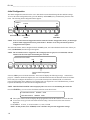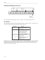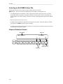
1
REF 9502-054-50A1
ELI 200
Operator’s
Manual
_________________________________________________________________________
CAUTION: Federal law restricts this device for sale to and use by or on the order of a physician.
®
Copyright© 2002
by Mortara Instrument, Inc.
7865 N. 86th Street
Milwaukee, Wisconsin 53224
This document contains confidential information that belongs to Mortara Instrument, Inc. No part of this document
may be transmitted, reproduced, used, or disclosed outside of the receiving organization without the express written
consent of Mortara Instrument, Inc. Mortara is a registered trademark of Mortara Instrument, Inc. ELI 200 is a
trademark of Mortara Instrument, Inc.
TEXT REF 9500-087-01A1
Technical Support and Service
Following are telephone numbers and addresses for contacting various technical support and service personnel.
Mortara Instrument, Inc.
7865 N. 86th St.
Milwaukee, WI 53224
Telephone Number: 414-354-1600
Toll-free Telephone Number: 800-231-7437
Toll-free Service Number: 888-MORTARA
Fax: 414-354-4760
E-mail address: [email protected]
24 hour technical support
Over 120 trained field service technicians
Same day shipment of replacement parts
Biomedical training classes
Extended warranties/service contracts
Sales Support/Supplies & Accessories
Mortara Instrument, Inc.
7865 N. 86th St.
Milwaukee, WI 53224
Phone: 414-354-1600
Fax: 414-354-4760
Internet: http://www.mortara.com
European Economic Community Representative
Mortara Rangoni
Via Oradour, 7 40016
San Giorgio di Piano
Bologna, Italy
Phone: 39-051-6645-360
Fax: 39-051-6651-012
Mortara Instrument, Inc., GMBH (Germany)
Henricistr. 124
45136 Essen
Telephone number: 49-201-268311
Fax: 49-201-268313
Mortara Instrument, Inc., B.V.
(The Netherlands).
H. Dunantplein 6
3731 CL De Bilt
Postbus 131
3720 AC Bilthoven
Telephone number: 31-30-2205050
Fax: 31-30-2201531
i
Notices
Manufacturer’s Responsibility
Mortara Instrument, Inc. is responsible for the effects on safety, and performance only if
•
Assembly operations, extensions, re-adjustments, modifications or repairs are carried out by persons authorized
by Mortara Instrument,
•
The electrical installation of the relevant room complies with the requirements of appropriate regulations, and
•
The ELI 200 is used in accordance with the instructions for use.
•
Upon request, Mortara will make available a service manual containing technical information to assist an
appropriately qualified individual with potential service related issues, though it is highly recommended that if
there are concerns regarding the devices performance, Mortara Service is contacted at 1-800-877-8942.
Responsibility of the Customer
The user of this product is responsible for ensuring the implementation of a satisfactory maintenance schedule.
Failure to do so may cause undue failure and possible health hazards.
Equipment Identification
Mortara Instrument equipment is identified by serial numbers on the back or bottom of the device. Care should be
taken so that these numbers are not defaced.
Information pertinent to tracking and manufacturing is found on the bottom of the product and may be called upon if
service of the device is required.
Copyright and Trademark Notices
This document contains information that is protected by copyright. All rights are reserved. No part of this
document may be photocopied, reproduced or translated to another language without prior written consent of
Mortara Instrument, Inc. The information contained in this document is subject to change without notice.
Other Important Information
The information in this document is subject to change without notice.
Mortara Instrument, Inc., makes no warranty of any kind with regard to this material, including, but not limited to
implied warranties of merchant ability and fitness for a particular purpose. Mortara Instrument, Inc., assumes no
responsibility for any errors of omissions that may appears in this document. Mortara Instrument makes no
commitment to update nor to keep current the information contained in this document.
ii
Warranty Information
Your Mortara Warranty
MORTARA INSTRUMENT, INC. (hereinafter referred to as “Mortara”) hereby warrants that Mortara products
(hereinafter referred to as “Products”) shall be free from defects in material and workmanship under normal use,
service and maintenance for the warranty period of such Product from Mortara or an authorized distributor or
representative of Mortara. Normal use, service and maintenance means operation and maintenance in accordance
with appropriate instructions and/or information guides. This Warranty does not apply to damage to the Products
caused by any or all of the following circumstances or conditions:
a) Freight damage;
b) Parts and/or accessories of the Products not obtained from or approved by Mortara;
c) Misapplication, misuse, abuse and failure to follow the Product instruction sheets and/or information
guides;
d) Accident, a disaster affecting the Products;
e) Alterations or modifications to the Products not authorized by Mortara;
f) Other events outside of Mortara’s reasonable control or not arising under normal operating
conditions.
THE REMEDY UNDER THIS WARRANTY IS LIMITED TO THE REPAIR OR REPLACEMENT WITHOUT
CHARGE FOR LABOR OR MATERIALS, OR ANY PRODUCTS FOUND UPON EXAMINATION BY
MORTARA TO HAVE BEEN DEFECTIVE. This remedy shall be conditioned upon receipt of notice by Mortara of
any alleged defects promptly after discovery thereof within the warranty period. Mortara’s obligations under the
foregoing warranty will further be conditioned upon the assumption by the purchaser of the Products (i) of all carrier
charges with respect to any Products returned to Mortara’s principal place or any other place as specifically
designated by Mortara or an authorized distributor or representative of Mortara, and (ii) all risk of loss in transit. It is
expressly agreed that the liability of Mortara is limited and that Mortara does not function as an insurer. A purchaser
of a Product, by its acceptance and purchase thereof, acknowledges and agrees that Mortara is not liable for loss,
harm or damage due directly or indirectly to an occurrence or consequence therefrom relating to the Products. If
Mortara should be found liable to anyone under any theory (except the expressed warranty set forth herein) for loss,
harm or damage, the liability of Mortara shall be limited to the lesser of the actual loss, harm or damage, or the
original purchase price of the Product when sold.
EXCLUDED FROM THE LIMITED WARRANTY SET FORTH ABOVE ARE CONSUMABLE ITEMS SUCH
AS PAPER, BATTERIES, ELECTRODES, PATIENT CABLES, LEAD WIRES AND MAGNETIC STORAGE
MEDIUMS.
EXCEPT AS SET FORTH HEREIN WITH RESPECT TO REIMBURSEMENT OF LABOR CHARGES, A
PURCHASER’S SOLE EXCLUSIVE REMEDY AGAINST MORTARA FOR CLAIMS RELATING TO THE
PRODUCTS FOR ANY AND ALL LOSSES AND DAMAGES RESULTING FROM ANY CAUSE SHALL BE
THE REPAIR OR REPLACEMENT OF DEFECTIVE PRODUCTS TO THE EXTENT THAT THE DEFECT IS
NOTICED AND MORTARA IS NOTIFIED WITHIN THE WARRANTY PERIOD. IN NO EVENT,
INCLUDING THE CLAIM FOR NEGLIGENCE, SHALL MORTARA BE LIABLE FOR INCIDENTAL,
SPECIAL OR CONSEQUENTIAL DAMAGES, OR FOR ANY OTHER LOSS, DAMAGE OR EXPENSE OF
ANY KIND, INCLUDING LOSS OF PROFITS, WHETHER UNDER TORT, NEGLIGENCE OR STRICT
LIABILITY THEORIES OF LAW, OR OTHERWISE. THIS WARRANTY IS EXPRESSLY IN LIEU OF ANY
OTHER WARRANTIES, EXPRESS OR IMPLIED, INCLUDING, BUT NOT LIMITED TO THE IMPLIED
WARRANTY OF MERCHANT ABILITY AND THE WARRANTY OF FITNESS FOR A PARTICULAR
PURPOSE.
iii
User Safety Information
Warning:
Caution:
Means there is the possibility of personal
injury to you or others.
Means there is the possibility of damage to
the equipment.
Provides information to further assist in the
use of the device.
Note:
Federal law restricts this device to sale by or on the order of a physician.
Warning(s)
•
Device (electrocardiograph, Class 1) captures and presents data reflecting a patient’s physiological condition
that when reviewed by a trained physician or clinician can be useful in determining a diagnosis. However, the
data should not be used as a sole means for determining a patient’s diagnosis.
•
To ensure that electrical safety is maintained during operation from AC (~) power, the device must be plugged
into a Hospital Grade outlet.
•
To maintain designed operator and patient safety, peripheral equipment and accessories used that can come in
direct patient contact, must be in compliance with UL 2601-1, IEC 601-1 and IEC 601-2-25.
•
To maintain designed operator and patient safety, only use parts and accessories supplied with the device and
available through Mortara Instrument, Inc.
•
To avoid the possibility of serious injury or death during patient defibrillation, do not come into contact with
device or patient cables. Additionally, proper placement of defibrillator paddles in relation to the electrodes is
required to minimize harm to the patient.
•
To ensure the safety of both the patient and the device, 1.5 meters (5 feet) of open area should surround the
patient.
•
A possible explosion hazard exists, do not use the device in the presence of flammable anesthetics.
•
ECG electrodes could cause skin irritation and should be examined for signs of irritation or inflammation.
•
Before attempting to use the device for clinical applications the operator must read and understand the contents
of the manual and any documents accompanying the device.
•
Where the integrity of external PROTECTIVE EARTH CONDUCTOR arrangement is in doubt, EQUIPMENT
shall be operated from its internal ELECTRICAL POWER SOURCE.
•
To maintain operator and patient safety, when connecting the ELI 200 to peripheral equipment not in
compliance with UL2601-1, IEC 601-1 or IEC 601-2-25, consideration should be given to the requirements of
IEC 601-1-1.
•
The ELI 200 has not been designed for use with high-frequency (HF) surgical equipment and does not provide a
protective means against hazards to the patient.
iv
•
When connected to an external modem, a protective earth conductor must be attached to the ELI 200. The
connection may be through the mains power supply cord, or by a separate protective earth conductor attached to
the metal chassis of the ELI 200. The external modem and its power supply must comply with the requirements
of IEC 60950, safety of information technology equipment, including electrical business equipment.
•
Leakage currents can increase if additional devices are connected to the patient.
•
All signal input and output (I/O) connectors are intended only for devices complying with EN 60601-1,
excluding the network connectors(s), that must only be used for connections to supporting Mortara Instrument
systems when cabling is supplied or approved by our Mortara Instrument Representative.
•
Connecting/disconnecting cable at the back of the device must be done with the device OFF (main power).
Caution(s)
•
To prevent possible damage to the keypad, do not use sharp or hard objects to depress keys, only use fingertips.
•
Do not attempt to clean the device or patient cables by submersing into a liquid, autoclaving, or steam cleaning.
•
Wipe the exterior surface of the device and patient cables with a sterilizing disinfectant, then dry with a clean
cloth.
•
Conductive parts of the patient cable, electrodes and associated Type CF connections, including the neutral
conductor of the patient cable and electrode, should not come into contact with other conductive parts, including
earth ground.
•
The rechargeable internal battery is a sealed lead acid type and it is totally maintenance free. If the battery
appears to become defective, refer to Mortara Instrument Service Department.
•
Do not pull or stretch patient cables as this could result in mechanical and/or electrical failures. Patient cables
should be stored after forming them into a loose loop.
•
The quality of the signal produced by the electrocardiograph may be adversely affected by the use of other
medical equipment, including but not limited to defibrillators and ultrasound machines.
v
Notes
•
Excessive patient movement could interfere with the operation of the device.
•
Proper patient preparation is important to proper application of ECG electrodes and operation of the device.
•
Patient cables should be checked for cracks or breakage in its exterior properties prior to use.
•
There is no known safety hazard if other equipment, such as pacemakers or other stimulators, are used
simultaneously with the ELI 200; however, disturbance to the signal may occur.
•
If the ECG input becomes inoperable due to excessive saturation or overload, the display will indicate a lead
fail for the lead(s) that this condition is present and if the signal is being printed the respective lead(s) will print
out as a square wave.
•
As defined by IEC 601-1 and IEC 601-2-25, the device is classified as follows:
- Class I equipment
- Type CF applied parts
- Ordinary equipment
- Not suitable for use in the presence of flammable anesthetics
- Continuous operation
•
The ELI 200 will automatically turn off (blank screen) if the batteries have been severely discharged.
•
After operating the ELI 200 using battery power, always reconnect the power cord and depress the I on the I/O
power switch. This ensures that the batteries will be recharged for the next time you use the ELI 200. The
word CHARGING or AC Power will appear on the LCD screen.
vi
Equipment Symbols
Symbol Delineation
Attention, consult accompanying documents
Alternating current
Protective earth (ground)
Earth (ground)
Fuse
Telephone line (modem)
Defibrillator-proof type CF input
Thermal paper
Equipotentiality
Output/Transmit
vii
Input
ON (power)
OFF (power)
"ON" only for part of Equipment
"OFF" only for part of Equipment
Stop (of action)
Shift key (to enter upper case text)
Space key
Enter key (accept data/return)
⌫
Backspace/Delete key
Initiate printing of 12-Lead ECG
viii
Initiate printing of continuous rhythm strip
High-speed serial data
Eject
Indicates compliance to applicable EEC directives
ix
Table of Contents
1
Introduction
Manual Purpose .............................................................................................................................................. 1-1
Audience ......................................................................................................................................................... 1-1
Conventions .................................................................................................................................................... 1-1
System Description ......................................................................................................................................... 1-1
ELI 200, Illustration ......................................................................................................................................... 1-2
ELI 200 Specifications..................................................................................................................................... 1-3
Setup and Installation...................................................................................................................................... 1-4
ELI 200, Two Views: Left Side and Rear ........................................................................................................ 1-4
Rear (Fuse Installation)................................................................................................................................... 1-5
Configuration Settings..................................................................................................................................... 1-5
Initial Configuration ......................................................................................................................................... 1-7
Protected Configuration .................................................................................................................................. 1-7
Protected Configuration Screen Summary ..................................................................................................... 1-8
Protected Configuration Screen A .................................................................................................................. 1-8
AC Filter .......................................................................................................................................................... 1-8
Storage Format ............................................................................................................................................... 1-8
Protected Configuration Screen B .................................................................................................................. 1-9
Storage Sensitivity .......................................................................................................................................... 1-9
Protected Configuration Screen C .................................................................................................................. 1-9
Plot Format...................................................................................................................................................... 1-9
Interpretation Format....................................................................................................................................... 1-9
Protected Configuration Screen D .................................................................................................................. 1-10
Plot Channels.................................................................................................................................................. 1-10
Protected Configuration Screen E .................................................................................................................. 1-11
Units ................................................................................................................................................................ 1-11
Date Format .................................................................................................................................................... 1-11
Protected Configuration Screen F................................................................................................................... 1-11
Baud Rate ....................................................................................................................................................... 1-11
Auto Delete ..................................................................................................................................................... 1-12
Protected Configuration Screen G .................................................................................................................. 1-12
Serial Port ....................................................................................................................................................... 1-12
CAPS Lock...................................................................................................................................................... 1-12
Protected Configuration Screen H .................................................................................................................. 1-12
Pre-append site number to patient ID ............................................................................................................. 1-13
Protected Configuration Screen I.................................................................................................................... 1-13
Phone Number ................................................................................................................................................ 1-13
Protected Configuration Screen J ................................................................................................................... 1-14
Internal Modem Baud Rate ............................................................................................................................. 1-14
Protected Configuration Screen K .................................................................................................................. 1-14
Auto Save........................................................................................................................................................ 1-14
Cueing ............................................................................................................................................................. 1-14
Protected Configuration Screen L................................................................................................................... 1-15
Site Number .................................................................................................................................................... 1-15
Cart Number.................................................................................................................................................... 1-15
Copies ............................................................................................................................................................. 1-15
Retrieve Serials............................................................................................................................................... 1-15
Protected Configuration Screen M.................................................................................................................. 1-15
ID Format ........................................................................................................................................................ 1-16
Protected Configuration Screen N .................................................................................................................. 1-16
Rhythm Lead Selection ................................................................................................................................... 1-17
x
Protected Configuration Screen O .................................................................................................................. 1-17
Site Name........................................................................................................................................................ 1-17
Protected Configuration Screen P .................................................................................................................. 1-17
Key Click Volume Setting................................................................................................................................ 1-18
Persistent Configuration.................................................................................................................................. 1-19
Load Thermal Paper ...................................................................................................................................... 1-20
Apply Power ................................................................................................................................................... 1-20
ELI 200 Supply List ......................................................................................................................................... 1-21
2
Operation
Starting the System......................................................................................................................................... 2-1
Operation......................................................................................................................................................... 2-1
AC Power Operation ....................................................................................................................................... 2-1
Battery Operation ............................................................................................................................................ 2-1
Patient Preparation ......................................................................................................................................... 2-2
Patient Hookup................................................................................................................................................ 2-2
ID Menu Formatting ........................................................................................................................................ 2-2
Selecting the ID Menu..................................................................................................................................... 2-3
ID Menu Prompts ............................................................................................................................................ 2-3
ID Menu Sequence (Long Format) ................................................................................................................. 2-5
3
Acquiring and Printing a 12-Lead ECG
ECG Selection Screen Description ................................................................................................................. 3-1
ECG Analysis .................................................................................................................................................. 3-2
ECG Activity Screen Description..................................................................................................................... 3-2
Taking a Second ECG .................................................................................................................................... 3-3
Selecting an E-SCRIBE Patient File ............................................................................................................... 3-4
Request Selection Screen............................................................................................................................... 3-4
4 Acquiring and Printing a Rhythm Strip
Rhythm Selection Screen Description ............................................................................................................ 4-1
Acquiring Routine Rhythm Strips .................................................................................................................... 4-1
Rhythm Activity Screen Description................................................................................................................ 4-1
5
Using the Special Functions
Special Function Screen Description .............................................................................................................. 5-1
Directory Description....................................................................................................................................... 5-1
Printing a Directory.......................................................................................................................................... 5-2
Directory Screen Sequence ............................................................................................................................ 5-2
Patient Selection Screen Description.............................................................................................................. 5-4
Selecting a Patient Name................................................................................................................................ 5-4
Erasing a Patient's ECGs................................................................................................................................ 5-4
Listing a Patient's ECGs.................................................................................................................................. 5-5
xi
Selecting a Specific ECG ................................................................................................................................ 5-5
Patient ID Screen Description......................................................................................................................... 5-5
Erasing a Specific ECG................................................................................................................................... 5-6
Maintenance on a Specific ECG ..................................................................................................................... 5-6
Directory Maintenance Screen Description..................................................................................................... 5-6
Updating or Adding Patient ID Information ..................................................................................................... 5-7
Transmitting ECGs.......................................................................................................................................... 5-7
Direct Connection Hookup .............................................................................................................................. 5-7
Telephone Connection Hookup ...................................................................................................................... 5-7
Sending ECGs ................................................................................................................................................ 5-8
Receiving ECGs.............................................................................................................................................. 5-8
Batch Plotting .................................................................................................................................................. 5-9
Downloading a Request List ........................................................................................................................... 5-9
Request Activity Screen Description............................................................................................................... 5-9
Printing the Request List .......................................................................................................... 5-10
6
Maintenance and Troubleshooting
Troubleshooting Chart..................................................................................................................................... 6-1
Self-Test Printout Description ......................................................................................................................... 6-2
Self-Test Printout Sample, Pg. 1 of 2.............................................................................................................. 6-3
Self-Test Printout Sample, Pg. 2 of 2.............................................................................................................. 6-4
Cleaning and Inspection.................................................................................................................................. 6-5
Inspecting the ELI 200 .................................................................................................................................... 6-5
Cleaning the ELI 200....................................................................................................................................... 6-5
Cleaning the Patient Cable ............................................................................................................................. 6-5
Cleaning the Writer Printhead......................................................................................................................... 6-5
Appendix
A System Information Log
System Information Log .................................................................................................................................. A-1
Appendix
B Sample Print Formats
Rhythm Strip (RHY) Description ..................................................................................................................... B-1
3-Channel ECG Format Description ............................................................................................................... B-1
4-Channel ECG Format Description ............................................................................................................... B-1
6-Channel ECG Format Description ............................................................................................................... B-1
3+3 ECG Format Description ......................................................................................................................... B-2
Measurement Matrix (MSR) Description......................................................................................................... B-2
Measurement Matrix Acronym List ................................................................................................................. B-2
Standard Rhythm Strip Sample (default, reduced) ......................................................................................... B-4
6-Channel Frontal Rhythm Sample (reduced) ................................................................................................ B-5
6-Channel Precordial Rhythm Sample (reduced) ........................................................................................... B-6
12-Channel Rhythm Sample (reduced) .......................................................................................................... B-7
3-Channel ECG Sample (reduced) ................................................................................................................. B-8
4-Channel ECG Sample (reduced) ................................................................................................................. B-9
6-Channel ECG Sample (reduced) ................................................................................................................. B-10
3+3 ECG Sample (reduced)............................................................................................................................ B-11
Measurement Matrix Sample (reduced).......................................................................................................... B-12
xii
Glossary .......................................................................................................................................................... G-1
Index................................................................................................................................................................ I-1
Figures
Figure 1-1 ELI 200 .......................................................................................................................................... 1-2
Figure 2-1 ELI 200 Left and Rear ................................................................................................................... 1-4
Figure 3-1 ELI 200 Rear (Fuse Installation).................................................................................................... 1-5
xiii
xiv
____________________________________________________________________________Section 1
1
Introduction
Manual Purpose
The ELI 200 Operator's Manual explains how to operate the ELI 200 interpretive, and non-interpretive
electrocardiographs. You can use this manual as a learning tool as well as a source of reference information. It
explains how to:
•
Set up the electrocardiograph.
•
Use and understand the keyboard, the viewing screen, and the menu sequences.
•
Enter, modify, and delete information.
•
Acquire a 12-lead electrocardiogram
•
Print an ECG rhythm strip
Audience
This manual is written for clinical research professionals. They are expected to have working knowledge of medical
procedures and terminology as required for monitoring cardiac patients.
Conventions
Text that the user must type, such as a:install, appears in bold, Times New Roman font.
Keys, such as ENTER, appear in bold, upper-case, Arial font.
Text that appears on the screen, such as C:\Portrait, appears in normal, Arial font.
System Description
The ELI 200 is a diagnostic electrocardiograph capable of acquiring and printing ECG data in a hospital and/or
clinical environment. If the ELI 200 is equipped with the computerized interpretation option installed and is
enabled, which is at the user’s discretion, the acquired electrocardiogram may assist in allowing the physician to
more quickly determine what care options may be available for the patient.
The printout offers a variety of formats: three, four or six channels in automatic mode and three, six, or twelve
channels during rhythm recording. The ELI 200 can operate on batteries or line power.
1-1
ELI 200_____________________________________________________________________________
The ELI 200 consists of:
•
•
•
•
Electrocardiograph
ELI 200 Operator’s Manual
Accessory Kit
- Paper, 8.5 x 11” thermal, cued, perforated, with header
- Alligator Clip Adapter 4mm, Set of 10
- Operator’s Manual
- Hospital Grade Power Cord
Patient Cable 10 Lead Resting
Figure 1-1, ELI 200, Illustration
Identification and
Part Number Label
1-2
____________________________________________________________________________Section 1
ELI 200 Specifications
Instrument Type:
12-lead interpretive electrocardiograph
Paper Type:
Thermal sensitive; full grid; 215mm by 60m
Recording Technique:
Computer-controlled thermal dot array; 80 dts/cm
Writer Speeds:
5, 10, 25, 50mm/sec; computer controlled
Recorder Time Resolution:
1 msec
Sensitivity:
5, 10, or 20mm/mV
Multiple Output Formats:
User selectable
Standard Leads:
I, II, III, aVR, aVL, aVF, V1, V2, V3, V4, V5, V6
Input Channels:
Simultaneous acquisition of all classical leads
Input Impedance:
47 megohm; defibrillator protected
Input Dynamic Range:
680mV
Electrode Offset
Tolerance:
320mVDC
Common Mode Rejection
Ratio:
100db as measured by ANSI/AAMI standard EC111991; up to 180db with digital processing
Patient Leakage Current:
Less than 10 micro-amperes with patient cable
connected. Meets the requirements of ANSI/AAMI
ES1.
Chassis Leakage Current:
Less than 100 micro-amperes. Meets the requirements
of ANSI/AAMI ES1.
Frequency Response:
Meets the requirements of ANSI/AAMI EC11 - 1991
A/D Conversion:
20 bits (1.17 microvolt LSB)
Digital Sampling Rate:
10,000s/sec/channel (used for pacemaker artifact
detection); 500s/sec/channel (used for recording and
analysis)
Special Computer
Functions:
Arm lead reversal detection; lead-off and/or artifact
detection; drift reduction; AC interference rejection
Power:
100-240VAC at 50 or 60 Hz, or internal batteries
Weight:
25 pounds
Dimensions:
14" by 17 1/2" by 4 3/4"
Environment:
Operating Temperature: +10 to +40 deg. C (+40 to
+ 140 deg. F)
Storage Temperature: -40 to +60 deg. C (-40 to +140
deg. F)
Humidity: 10% - 95%, non-condensing
Altitude: From sea level to 15, 000 feet
1-3
ELI 200_____________________________________________________________________________
Setup and Installation
Figure 2-1, ELI 200, Two Views
Left Side
Serial Connector
AC On/Off Switch
Internal Modem Connector
(If Supplied)
Patient Cable Connector
Rear
Battery Fuse
Caution: When the fuse is installed, battery will gradually discharge over time. To
guarantee battery life, always connect the power cord and depress the I on the I/O power
switch to ensure the batteries will be recharged for your next use. The word CHARGING or AC
Power will appear on the LCD screen. If fuse is removed, stored data and configuration
settings will be lost.
The battery fuse is installed in the back of the unit, as pictured above. The fuse is installed so the ELI 200 can store
data, operate on the internal battery, and save the configuration settings.
One end of the fuse is covered with a plastic tip; the other end has a silver cap. If a new fuse needs to be installed,
follow the steps below:
n Hold the fuse by the plastic tip and insert the silver-capped end into the round socket, which is located near
the fuse “Warning” instructions on the back of the ELI 200.
o Rotate the fuse in the socket so that approximately 1/4" of the plastic cap sticks out.
p In a clockwise motion, press the plastic cap into the socket using your thumb or a screwdriver. The cap
should be almost flush with the unit.
1-4
____________________________________________________________________________Section 1
Figure 3-1, Rear (Fuse Installation)
Battery Fuse
NOTE: If you remove the battery fuse after the ELI 200 is in operation, any ECGs stored in the unit will be lost
and the initial and protected configuration settings will change to their default settings. The persistent
site and cart number configuration settings will be preserved.
NOTE: If the main switch is ON and the LCD (Liquid Crystal Display) does not display “charging” or “AC
Power,” have a qualified service technician verify that the line fuse(s) are installed.
Configuration Settings
Three configuration programs define all ELI 200 operational conditions:
1.
Initial Configuration
a. Download Custom ID
b. Clock and Date settings
2.
Protected Configuration
a. AC Filter, Storage Format
b. Storage Sensitivity
c. Plot Format, Interpretation Format
d. Plot Frequency and Plot Channels
e. Units, Date Format
f. Baud Rate, Auto Delete
g. Serial Port, Caps Lock
h. Include Site # in ID
i. Phone Number
j. Auto Save, Cueing
k. Copies, Retrieve Serials
l. ID format
m. Rhythm Lead Selection
n. Site Name
o. Key Click
3.
Persistent Configuration
a. Site Number
b. Cart Number
1-5
ELI 200_____________________________________________________________________________
Initial Configuration
The initial configuration menu allows the user to download a custom ID and change the date and time settings.
To access the initial configuration menu, press the ALT key and the SPF (0) key simultaneously from the main
menu. The following initial configuration menu appears:
DWNLD
ID
ALT
0
CLOCK
1
Custom ID Format
EX
2
3
4
5
6
7
8
Date and Time
Screen
9
Exit to
Main Menu
NOTE: To access the Protected Configuration and Persistent Site Number Configuration menus, you must begin
from the initial configuration menu as pictured above. Details to access the protected and persistent
configuration menus follow.
The custom ID format, which is designed in the E-SCRIBE system, can be downloaded to the ELI 200. When you
select (0) DWNLD ID, the following screen appears:
NOTE: The site number must be configured in the cardiograph and recognized as an established, valid site
number at the E-Scribe before downloading the custom ID.
Download custom format?
YES
ALT
0
1
2
3
NO
4
5
6
7
8
9
Back to Initial Configuration
Menu
Select (4) YES to proceed with the download – the screen will display the following message: “connection in
progress”. When the download completes, the new CUSTOM format becomes the ID menu format for all future
ECGs until you reconfigure the ID format. If you reset the format option to SHORT, STD, or LONG in the
protected configuration menu, and then wish to change back to an original or a new CUSTOM format, you must
repeat the download process from the initial configuration menu.
NOTE: CONNECTION FAILURE will be displayed if there was an error in downloading the custom ID.
Press the CLOCK key (2) to access the Clock/Date Selection screen shown below.
Current date and time:
New date and time:
00/00/00
00/00/00
00:00
00:00
n The top line of the LCD screen displays the preprogrammed current date and time set for the ELI 200.
o To reset the clock, type in the correct date and time (using a 24-hour clock) in the same format as
displayed.
US EXAMPLE: 12/31/89, 17:55 for December 31, 1989, 5:55 PM
NOTE: the date format (US or EUROPE) can be switched in the protected configuration settings.
1-6
____________________________________________________________________________Section 1
Protected Configuration
The protected configuration menu allows the user to define the ELI 200 operational conditions that do not change on
a daily or patient-to-patient basis. Once you set these default conditions, you will rarely need to use the protected
configuration program again. To access the protected configuration menu, press the ALT key and the C key
simultaneously from the initial configuration menu.
The chart below summarizes the protected configuration menu screens and the available options for each parameter.
Detailed descriptions of the parameters for each menu option(s) follow the summary chart..
Protected Configuration Screen Summary
Screen
A
Parameter
Option
AC Filter
60Hz or 50Hz
Storage Format
2.5 seconds or 10 seconds
B
Storage Sensitivity
2.5 micro-volts or 10 micro-volts.
C
Plot Format
Interpretation Format
Interpretation or No Interpretation
Reason Statements or No Reason Statements
D
Plot Frequency
40Hz or 150Hz
Plot Channels
3+3, 3, 4, 6
Units
LB/IN or kg/cm
Date Format
US or European
Baud Rate
38400
Auto Delete
XMT, XMT/PLT, IMMED, OFF, PLT
Serial Port
Direct or Modem
Caps Lock
On or Off
H
Include Site # ID
Yes or No
I
Phone Number
User-defined (up to 40 characters including special
characters)
J
Modem Baud Rate
1200 or 2400
K
Auto Save
ON or OFF
Cueing
ON or OFF
E
F
G
1-7
ELI 200_____________________________________________________________________________
L
Site Number
Display only
Cart Number
Display only
Copies
0 = Original copy
1 = Original plus one copy
x = Original plus up to nine copies
Retrieve Serials
0 = Most recent ECG (value should always be
set to 0).
M
ID Format
LONG, SHORT, CUSTOM, STD
N
Rhythm Lead
Selection
Channel 1, Channel 2, Channel 3: I, II, III, aVR,
aVL, aVF, V1-V6
O
Site Name
User-defined (up to 32 alphanumeric characters)
P
Key Click
Soft, Medium, Loud
To advance from one configuration screen to the next, press the ENTER key. Select (9) EX from any protected
configuration screen to return to the initial configuration screen.
Protected Configuration Screen A
AC
Filter:
ALT
0
Storage
Format:
60Hz
1
2
3
4
5
2.5s
6
EX
7
8
9
Exit to
Main Menu
AC Filter
The ELI 200 software removes 60Hz or 50Hz interference. Which setting you select depends on the line frequency
in your country. Always use the 60Hz setting in the United States. If the AC interference is present, check to see
that the proper AC filter is selected.
Storage Format
There are two available storage format options in the ELI 200. One format stores 2.5 seconds of each of the twelve
leads. The other storage format option, which is the default setting, stores the full 10 seconds of all twelve leads.
Selecting this storage format option will reduce the amount of storage. For optimum storage capacity, select 2.5
seconds.
Most users select the 2.5 second storage format since it provides the standard 12-lead record. If the default Plot
Channels option is set to 4 channels (see Configuration Screen C), the 2.5 second format is modified so that 10
seconds of Lead II is stored along with 2.5 second segments of the remaining leads.
1-8
____________________________________________________________________________Section 1
Protected Configuration Screen B
Storage
Sensitivity:
ALT
0
1
2.5uV
2
3
4
EX
5
6
7
8
9
Exit to
Main Menu
Storage Sensitivity
The default storage sensitivity is 2.5 uV. For optimum storage capacity, select 10 uV.
Protected Configuration Screen C
Plot
Format:
ALT
0
1
Interp
INT
2
Format:
3
4
5
REA
6
EX
7
8
9
Exit to
Main Menu
Plot Format
The ELI 200 automatically analyzes ECGs and prints the interpretation on the ECG printout. The Plot Format
option allows you to select or suppress the “interpretive” text on the ECG report.
NOTE: A qualified physician should review the computer generated ECG interpretation before the treatment of
any patient.
Interpretation Format
The reason statements indicate why a particular interpretive statement was printed. Reason statements print in
[square brackets] within the interpretive text (if the interpretation is turned on). Turning the reason statement
function on or off does not affect the measurements performed or the interpretive statements selected by the analysis
program. See Appendix B for examples of the reason statements on the sample printouts.
1-9
ELI 200_____________________________________________________________________________
Protected Configuration Screen D
Plot
Freq:
ALT
0
Plot
Channels:
150Hz
1
2
3
4
5
3
6
EX
7
8
9
Exit to
Main Menu
The ECG plot frequency default setting is 150Hz, or select 40Hz. The recommended setting is 150Hz.
Plot Channels
This option defines the default for one of four available plot channels. The default setting is 3+3 plot channels. See
Appendix B for sample printouts of the plot channels. The plot options are:
Format Option
3
ECG Data
2.5-second graph of 12 leads in
a 3-channel format
4
Condensed graph of 12 leads
in a 4-channel format (3 channels
contain 2.5 seconds of data for
each lead; 4th channel is a
10-second rhythm strip of Lead II)
6
5.0-second graph of 12 leads in
a 6-channel format
3+3
Standard format PLUS a
3-channel, 10-second rhythm strip
of Leads V1, II, V5
Independent of a 2.5s storage format, the cardiograph will store 5 seconds of limb leads and 5 seconds of precordial
leads at a 6 channel – plot channels format so the full ecg can be retrieved from memory and re-printed. However,
for optimum storage capacity, select 3 plot channels. When this setting is used, only 2.5s of each lead is stored
resulting in less total storage requirements.
1-10
____________________________________________________________________________Section 1
Protected Configuration Screen E
Units:
ALT
0
Date
Format:
LB/IN
1
2
3
4
5
US
6
EX
7
8
9
Exit to
Main Menu
Units
This option defines the units of weight and height to either pounds/inches (LB/IN) or kilograms/centimeters
(kg/cm).
Date Format
This option defines the format for displaying the date and time in either the U.S. format (12/31/98; 17:50) or the
European format (31.12.98; 17:50).
NOTE: To change the date (and time) select (2) CLOCK from the initial configuration menu as explained earlier
in this chapter.
Protected Configuration Screen F
Baud
Rate:
ALT
0
Auto
Delete:
38400
1
2
3
4
5
OFF
6
EX
7
8
9
Exit to
Main Menu
Baud Rate
The baud rate determines the serial port’s data transmission rate in bits per second (bps). The baud rate is set to
38400 bps for direct data transmission between the ELI 200 and another unit; and for a direct connection to the ESCRIBE system; and for use with an external modem.
1-11
ELI 200_____________________________________________________________________________
Auto Delete
This option defines the ECG auto delete status in the directory. Deleted ECGs will be removed as the directory
becomes full. The selections are:
OFF = ECG is never automatically deleted from the directory.
PLT = ECG is automatically deleted from the directory after plotting.
XMT = ECG is automatically deleted from the directory after transmission.
XMT/PLT = ECG is automatically deleted from the directory after transmission and plotting.
IMMED = ECG is automatically deleted.
NOTE: The initial ECG printout does not activate the procedures described above for the plot option.
Protected Configuration Screen G
Serial
Port:
ALT
0
CAPS
Lock:
MODEM
1
2
3
4
ON
5
6
EX
7
8
9
Exit to
Main Menu
Serial Port
This option specifies the serial port mode by either direct connection or external modem. If an internal modem is
present, the cardiograph will check for a dial tone and use it by default.
CAPS Lock
When the CAPS lock is on, all characters shall be translated to upper case, and the shift key shall cause the
characters to be lower case. The default setting is on.
Protected Configuration Screen H
Include
Site # in ID:
ALT
0
1
EX
NO
2
3
4
5
6
7
8
9
Exit to
Main Menu
1-12
____________________________________________________________________________Section 1
Pre-append site number to patient ID
When yes is selected for this configuration setting, the site ID, followed by a dash, will be displayed when the user
enters the patient ID. The user will not be able to erase the site ID and dash before entering the patient ID. The
patient ID with the site ID pre-appended shall become the true patient ID and be displayed that way whenever the
patient ID is displayed and printed.
Protected Configuration Screen I
Phone number:
0
ALT
1
2
3
4
5
6
7
8
9
Phone Number
This option specifies the phone number for the ECG transmission destination (another unit or an E-SCRIBE
system). Enter up to 40 characters. Special characters may be added using the ALT - key combinations, listed
below. Use the BACKSPACE key to erase an entry error.
ALT-Key
1
2
3
4
5
6
7
8
9
0
A
B
C
D
E
I
K
L
M
N
O
P
Q
R
S
T
U
V
W
X
Y
Character
!
@
#
$
%
^
&
*
(
)
~
\
,
=
{
[
]
<
>
}
+
?
"
/
'
;
`
|
.
:
ELI Display
right arrow
Japanese Yen
1-13
ELI 200_____________________________________________________________________________
To insert a pause for an additional dial tone, use the letter W. For example, you may need to dial a 9 to get an
outside line.
EXAMPLE: 9W14145554321
To change tone dialing to pulse dialing, use the letter P.
EXAMPLE: P14145554321
(If necessary, you can use both the letter W and the letter P in the same phone number.)
Protected Configuration Screen J
Mo d e m B au d
Rate :
ALT
0
2400
1
2
3
4
5
6
7
8
9
Internal Modem Baud Rate
The default setting for this option is 2400 bps for telephone transmission. It is recommended that the 2400 default
setting be used at all times. If you find that you are having frequent transmit (XMT) failures due to poor telephone
line quality, press the 2 softkey to change the baud rate to 1200.
Protected Configuration Screen K
AUTO
SAVE
ALT
0
ON
1
2
Cueing:
3
4
5
ON
6
EX
7
8
9
Exit to
Main Menu
Auto Save
This option defines whether or not the ELI 200 is to save all newly acquired ECGs in the directory. If the selected
configuration option is set to OFF, the ELI 200 asks if you wish to save each new ECG after it prints. A “YES”
answer saves the ECG in the directory.
Cueing
The ELI 200 contains an optical sensor in the writer that aligns a black rectangle on the back of the thermal paper
with a predetermined starting point for printing. If the Cueing option is ON, every 12-lead ECG printout stays
within the perforation lines, which are placed every 11 inches. If the Cueing option is OFF, each printout begins
directly after the preceding printout regardless of the location of the perforation lines.
1-14
____________________________________________________________________________Section 1
Protected Configuration Screen L
Site#:
Cart#:
ALT
Copies: 0
Retrieve Serials: 0
0
1
2
3
4
5
6
7
8
9
Site Number
Read only Display. This option identifies the site of your ELI 200. Site numbers designate the hospital, clinic, or
institution for ECG records stored in a Mortara Instrument, Inc., E-SCRIBE system and must be defined for
transmitting. You can use up to four digits for the site number; numbers from 0 to 9999 are supported. See
Persistent Configuration for details to edit site number.
Cart Number
Read only Display. Cart numbers indicate which electrocardiograph transmitted a particular ECG. You can use up
to four digits for the cart number; numbers from 0 to 9999 are supported. See Persistent Configuration for details to
edit cart number.
Copies
This option defines the number of printed copies when an ECG is taken. A zero (0) setting prints the original only;
one (1) prints the original plus 1 copy; two (2) prints the original plus 2 or more copies (up to 9 copies).
You can request copies from the ECG Activity screen, which appears after ECG acquisition. You also can request
copies while in the directory from the Directory Maintenance screen.
Retrieve Serials
This value should always be set to 0.
Protected Configuration Screen M
ID
Format:
ALT
0
1
LONG
2
EX
3
4
5
6
7
8
9
Exit to
Main Menu
1-15
ELI 200_____________________________________________________________________________
ID Format
This option defines the format for the patient ID information prompts. There are four available formats: SHORT,
STD, LONG, or CUSTOM.
The SHORT format includes the patient's last name, patient ID number, age, and sex prompts.
The STANDARD format includes the patient's last name, patient ID number, age, height, weight, sex, race,
medication 1 selection, medication 2 selection, and the Location field.
The LONG format is identical to the STD format except that it includes the patient's first name, room and comment
fields.
The CUSTOM format, which is designed in the E-SCRIBE system, can be downloaded to the ELI 200. When you
select the CUSTOM format and press the ENTER key, the following screen appears.
Download custom format?
YES
ALT
0
1
2
3
4
NO
5
6
EX
7
8
9
Exit to
Main Menu
Before you download the CUSTOM format, set up the defined configuration for ECG transmission (either a direct
hookup or a telephone connection). Press YES to receive the customized ID format, and connect the
electrocardiograph accordingly.
When the download completes, the CUSTOM format becomes the ID menu format for all future ECGs until you
reconfigure the ID format. If you reset the format option to SHORT, STD, or LONG, and then wish to change back
to an original or a new CUSTOM format, you must repeat the download process.
NOTE: Also see Initial Configuration section to download custom ID.
Protected Configuration Screen N
Rhythm lead
selection:
ALT
0
1
2
3
CH1
II
CH2
V1
CH3
V5
4
5
6
EX
7
8
9
Exit to
Main Menu
1-16
____________________________________________________________________________Section 1
Rhythm Lead Selection
This option defines the programmable rhythm strip selections for 3-channel rhythm strips. Using the 4, 5, and 6 soft
keys, you can toggle through each of the 12 leads to select the entries for the three channels.
The factory-set default values are:
Channel 1: Lead II
Channel 2: V1
Channel 3: V5
You can also print the standard lead groups (I-II-III, aVR-aVL-aVF, V1-V2-V3, V4-V5-V6), and the Frontal group
in a 6-channel format (I-II-III-aVR-aVL-aVF), and a Precordial group in a 6-channel format (V1-V2-V3-V4-V5V6) by toggling the GRP key on the Rhythm Activity screen while the rhythm strips are printing.
NOTE: You can print a 12-channel format by pressing RHY in the special functions menu. (See Section 5.)
Protected Configuration Screen O
Site Name:
ALT
0
1
2
3
4
5
6
7
8
9
Site Name
This option defines your clinic, hospital, or office name. You can enter up to 32 alphanumeric characters. The site
name prints just left of center at the bottom of the ECG printout.
Protected Configuration Screen P
Key
Click:
ALT
0
Soft
1
2
3
4
5
6
7
8
9
1-17
ELI 200_____________________________________________________________________________
Key Click Volume Setting
This option defines the data entry click loudness. Press the soft key (2) to toggle through and select soft, medium or
loud.
EXTERNAL MODEM
The external modem initialization string is accessed by selecting ALT + SPF from the main menu and then ALT +
I. The modem command sequence can be entered and shall allow the user to enter special characters required by
some modem commands. These special characters can be entered using the ALT key in combination with the
following keys:
ALT-Key
Character
ELI Display
1
2
3
4
5
6
7
8
9
0
A
B
C
D
E
I
K
L
M
N
O
P
Q
R
S
T
U
V
W
X
Y
!
@
#
$
%
^
&
*
(
)
~
\
,
=
{
[
]
<
>
}
+
?
"
/
'
;
`
|
.
:
right arrow
Japanese Yen
Before using your modem, you must configure it for country-specific operation. This is also true if you move the
modem to a different country after it has been configured for country-specific operation. The following list of
countries require "%T19,0,XX" to be added to the modem initialization string. Where “XX” is replaced by the
number in the following table. The "%T19,0,XX" should be removed for all other countries.
1-18
____________________________________________________________________________Section 1
%T19, 0, XX
Country
XX
Australia
01
Czech Republic 25
Hong Kong
30
Hungary
30
India
30
Indonesia
30
Japan
10
Korea
30
New Zealand
09
Philippines
30
Poland
30
Singapore
30
South Africa
35
Slovenia
30
Persistent Configuration
The persistent configuration menu allows the user to define the site number and the cart number.
Begin from the Initial Configuration menu (ALT+SPF from the main screen).
Select ALT + D, to display the current site number and cart number.
Site#:
Cart#:
ALT
0
1
2
3
4
5
6
7
8
9
8
9
Select ALT + P, to program the new site number and/or cart number.
Site#:
Cart#:
ALT
0
1
2
3
4
5
6
7
You may enter up to four digits for the site and cart numbers; numbers from 0 to 9999 are supported.
NOTE: When site # and cart # are left blank and the ecg is printed from memory, the value for site # and cart #
will be 0 on the printout.
1-19
ELI 200_____________________________________________________________________________
After the new numbers are entered, the user will have the option of saving them to FLASH memory.
Saving new #’s will erase directory.
Save new #’s?:
ALT
0
1
2
3
4
YES
5
6
NO
7
8
9
If you choose to save the newly programmed site and cart numbers, the following message appears:
Program FLASH with new Site/Cart #’s?
YES
ALT
0
1
2
3
4
5
NO
6
7
8
9
Load Thermal Paper
To load paper into the thermal dot-array writer:
n Press the black button on the top of the writer to release the cover latch.
o Pull up on the cover from the left to open the writer cover.
p Insert the 8 1/2"roll of thermal paper (Mortara part number 9100-006) into the writer following the diagram
on the inside of the writer.
q Pull out the end of the paper roll to approximately 4" beyond the closure point of the writer. The adhesive
tab should be outside the writer and not come in contact with the printhead.
r Lower the writer cover and press down on the top until the cover latches. DO NOT press along the cutting
edge to close the cover; there is no support above the writer edge.
To remove an ECG report from the writer:
Grasp the left end of the report along the top and pull the paper up and to the right. The printhead acts as the cutting
edge.
Apply Power
To apply power to the electrocardiograph unit:
n Plug the power cord into an AC wall outlet and into the back of the ELI 200.
o Flip up the I/0 power switch, located on the left side of the unit, to the I position (flat to the side of the unit).
The I/0 power switch can and should remain in the I position at all times.
When you turn on the power switch, the word AC POWER (or CHARGING if the batteries are low) appears on the
LCD (liquid crystal display) screen. After eight hours of charging without operation, the internal battery will be
fully charged.
1-20
____________________________________________________________________________Section 1
ELI 200 Supply List
Standard ELI 200 orders include the following accessories:
•
•
•
•
•
•
REF 3181-008/ -002
REF 9502-054-50
REF 9100-008-01
REF 9300-033-51
REF 9293-021-50/ -51
REF 9325-001-50
Hospital Grade Power Cord Domestic / International
ELI 200 Operator’s Manual
ELI 200 Paper 8.5 x 11” thermal, cued, perforated, with header
Resting Tab-type Electrodes, Box of 500
Patient Cable 10 Lead Resting Domestic/ International
Alligator Clip Adapter 4mm, Set of 10
To order additional supplies, contact a Mortara Instrument customer service representative at:
Mortara Instrument, Inc.
7865 N. 86th Street
Milwaukee, WI 53224
Phone: 888-MORTARA
(414) 354-1600
Fax: (414) 354-4760
Internet: http://www.mortara.com
1-21
ELI 200_____________________________________________________________________________
1-22
____________________________________________________________________________Section 2
2
Operation
Starting the System
Operation
The ELI 200 operates on AC power or an internal, rechargeable battery.
AC Power Operation
To operate using AC power:
n Plug the AC power cord (use hospital grade) into the left rear receptacle of the ELI 200.
o Depress the I on the I/0 power switch located on the left rear of the ELI 200.
p The words AC POWER appear on the LCD screen.
ELI 200
AC POWER
If the batteries need charging, the word CHARGING is displayed on the LCD screen.
ELI 200
CHARGING
The internal batteries are fully charged after eight hours of charging without use of the ELI 200.
Battery Operation
When fully charged, the ELI 200 can operate on batteries for approximately 4 hours.
To operate using battery power:
n Flip up the I/0 power switch, located on the left side of the unit, to the I position (flat to the side of the unit).
The I/0 power switch can and should remain in the I position at all times.
o Press the ON/OFF/DC key located on the left side of the keyboard.
The words SELF TEST appear briefly on the LCD screen followed by the Main Menu screen.
If the batteries are not charged adequately, the message BATTERY LOW appears on the LCD screen.
If the battery fuse is not installed correctly or is not functioning, a blank screen is displayed on the ELI 200. See
Section 6, “Troubleshooting.”
2-1
ELI 200_____________________________________________________________________________
WARNING: The ELI 200 will automatically turn off (blank screen) if the batteries have been severely
discharged.
NOTE: If no keys are pressed for about four minutes, the ELI 200 turns itself off to conserve battery power. The
only exception to this operation is when the user prints a continuous rhythm strip or if the AC power is
on. (If no keys are pressed for about one minute from the main menu, the Eli 200 will turn off).
WARNING: After operating the ELI 200 using battery power, always reconnect the power cord and depress the I
on the I/O power switch. This ensures that the batteries will be recharged for the next time you use
the ELI 200. The word CHARGING or AC Power will appear on the LCD screen.
Patient Preparation
Correct electrode placement is important for acquiring a successful ECG (see Patient Hookup below). Consider
performing some patient preparation procedures to remove oils, lotions, and hair from the skin, particularly on obese
individuals.
Patient Hookup
ID Menu Formatting
The ELI 200 provides four possible formats (LONG, SHORT, STANDARD, or CUSTOM) for entering patient
identification information.
2-2
____________________________________________________________________________Section 2
Selecting the ID Menu
You should enter patient identification information for each patient at the beginning of a session.
To access the ID data entry menu:
•
Press the ID key (9) on the Main Menu.
OR
•
Press either the ECG (electrocardiogram) or RHY (rhythm strip) function key and answer YES to the
“New Patient?” question that follows.
New Patient?
ALT
0
1
YES
2
3
4
STAT
5
6
7
REQ
8
9
NOTE: If the patient is connected to the electrocardiograph and you press the ECG or RHY key, the ELI 200
automatically begins the 10-second ECG acquisition while you are entering the patient's identification
data. Therefore, you should instruct the patient to relax in a recumbent position to ensure that the ECG
is free from noise and artifact due to patient activity.
If you press the ID key from the Main Menu to enter new patient information, the entered information is stored in
memory. After completing the ID menu sequence and returning to the Main Menu, you must press the ECG or
RHY function key to run an ECG or rhythm strip.
2-3
ELI 200_____________________________________________________________________________
ID Menu Prompts
Depending on the ID format configured at setup, a series of LCD prompts tells you what patient information to
enter. After you type in the requested data and press the ENTER key, the blinking cursor moves sequentially to the
next data entry field. Regardless of the ID format selected in the protected configuration, the patient ID field can be
entered with upper case alphanumeric characters.
NOTE: Site number may be pre-appended to the patient ID depending on the protected configuration setting.
You should always complete the Name and Patient ID Number fields. For units with interpretive software, it is
necessary to enter the patient’s age and sex for an accurate reading. To skip other data entry fields, do not type in
any information in the field and press the ENTER key. Skipped fields appear as a blank field on the ECG report.
NOTE: If date of birth field is used in a custom ID format, the entry of the date of birth will automatically
calculate patient’s age. The date format can be configured for US or European format.
Sample ID Screen Prompt
Last name:
ALT
0
Prompt
2-4
1
2
3
Blinking Cursor
4
5
6
7
8
9
____________________________________________________________________________Section 2
ID Menu Sequence, Long Format
Screen Prompts
Data Entry Instructions
Last name:
Type the patient's last name (up to 20 characters).
Press ENTER.
First name:
Type the patient's first name (up to 10 characters).
Press ENTER.
Patient ID:
Type the patient's identification number (up to 12 digits)
using the numeric keys. Press ENTER.
Age:
Type patient's age (up to 3 digits). Press ENTER.
Ht:
Type patient's height using inches or centimeters (up to 3
digits). Press ENTER.
Wt:
Type patient's weight in pounds or kilograms (up to 3
digits). Press ENTER.
Sex:
Type the letter “M” for male or "F" for female OR press the
forward and backward arrows (soft keys 8 and 9) to enter
male or female. If you do not make a selection, the entry
defaults to male. Press ENTER.
Race:
Type the first letter of the patient's race:
C = Caucasian
B = Black
H = Hispanic
O = Oriental
OR press the forward or backward arrows (soft keys 8 and 9) to
scroll the list for a selection. A "blank" selection is provided for
unknown race. Stop at the race you want to select and press
ENTER.
2-5
ELI 200_____________________________________________________________________________
ID Menu Sequence, Long Format, Continued
Medication 1:
Press the forward or backward arrows (soft keys 8 and 9) to
scroll the list of 10 groups for a selection:
Blank (no entry)
Digitalis
Beta Blocker
Quinidine/Norpace
Diuretic
Calcium Antagonist
Proc/Lido/Tocainide
Other Antiarrhythmic
Psychotropic
Unknown
Stop at the medication you want to select and press ENTER.
Medication 2:
Repeat instructions for Medication 1.
Press ENTER.
Location:
You can use this field to enter the patient's room number or any
other user-defined information (up to 5 alphanumeric
characters).
Press ENTER.
Room:
Use this field to enter the patient's room number (up to 5
alphanumeric characters).
Press ENTER.
Comment:
2-6
Use this field to further identify a room number, list patient
symptoms, or add any other user-defined information (up to 20
character spaces).
Press ENTER.
______________________________________________________________________Section 3
3
Acquiring and Printing a 12-Lead ECG
ECG Selection Screen Description
New Patient?
ALT
0
1
YES
2
3
4
Enter New Patient
Information
STAT
5
6
7
Emergency
ECG
REQ
8
9
Request
E-SCRIBE Files
The ECG Selection screen appears if you press the ECG function key before entering patient identification
information on the ID menu.
The YES key (4) allows you to access the ID data entry menu to add new patient information.
The STAT key (7) allows you to acquire an emergency ECG. You can add the patient's identification
information later by editing the ID fields from the ECG directory. See Section 5 for instructions on using
the ECG directory.
The REQ key (9) enables you to select a patient from the E-SCRIBE request list. The list may contain all
the patient's ID information, which you can add to an ECG.
You should begin routine ECGs by connecting the patient to the ELI 200 and entering the patient
identification information as described in Section 2. After you complete the last data entry field on the ID
menu and press the ENTER key, the LCD screen displays the following status condition:
10:21:15
Rate: 60
Acquiring ECG
If the patient has been connected correctly for 10 seconds, the “Acquiring ECG” message is displayed only
momentarily.
If there is excessive noise or lead(s) failure during the acquisition of the ECG, the following screen
appears:
10:25:21
LA/V2
Rate: 60
WAITING FOR GOOD DATA
The top line of the LCD screen shows the lead or leads that are not properly attached or that are not sending
clear data. The screen display sample "LA/V2" identifies a lead fail of the left arm (LA) and V2 chest lead.
When the problem is corrected, the ELI 200 waits for 10 seconds of good data before analyzing
the ECG. If you cannot correct the problem, you can override the message by pressing the ECG key a
second time.
3-1
ELI 200_______________________________________________________________________
ECG Analysis
The ELI 200 analyzes the ECG in approximately three seconds. The LCD screen briefly displays the
following status condition:
ANALYZING ECG
The writer then prints an 8 1/2" by 11" strip that graphs the 12-lead ECG data in the format selected at
setup. See Appendix B for descriptions and illustrations of the ECG print formats.
SAVE ECG?
YES
NO
If the Auto Save screen is set to OFF, the system displays this screen after printing the ECG. Press YES
(4) to save the ECG and store it in the system’s memory. If you press NO (6), the ECG will not be saved
and stored.
ECG Activity Screen Description
Patient Name
Patient ID
Name: Robertson
CPY
ALT
0
Copy
ID: 34567809
4CH 25mm/s
1
2
Writer Speed
Format
Selection Key
10mm/mV
3
4
Gain
100Hz
5
6
7
Plot Frequency
INT
EX
8
9
Exit
Interpretation or
NO Interpretation
The ECG Activity screen appears after the writer prints the ECG data. On this screen you can change the
writer speed, gain, plot frequency, and the interpretation option. You also can print copies of the ECG
report in any of the four available plot formats or print the Measurement Matrix. To select the printing
format parameters, toggle the Format Selection (1) key.
3-2
______________________________________________________________________Section 3
Format Option
ECG Data
3
2.5-second graph of 12 leads in
a 3-channel format
4
Condensed graph of 12 leads
in a 4-channel format (3 channels
contain 2.5 seconds of data for
each lead; 4th channel is a 10second rhythm strip of Lead II)
6
5.0-second graph of 12 leads in a
6-channel format
Standard format PLUS a 3channel, 10-second rhythm strip
of Leads V1, II, V5
3+3
Table containing amplitude (uV)
and duration (ms) measurements
for generating ECG interpretation
MSR
(Measurement
Matrix
The CPY key (0) allows you to make an additional copy of the ECG report. Select the printing format
instructions for each copy before you press the CPY key.
The Format Selection key (1) allows you to select the copy format.
The INT/NO INT key (8) allows you to copy an ECG with the interpretation (INT) printout or without the
interpretation printout (NO INT).
The EX key (9) returns you to the Main Menu and deletes the ECG if it was not saved.
Taking a Second ECG
If you need to take a second electrocardiogram on the same patient after the first one has printed, press the
EX (exit) key to access the Main Menu. Then press the ECG function key. The LCD displays the
following screen:
Name : Ro be rtso n
ID: 3 45 6 7 0 9
Ne w Patie nt?
ALT
0
1
2
3
YES
NO
4
5
S TAT
6
7
REQ
8
9
Since the patient's ID information is stored in memory, you can acquire another ECG by answering NO
(soft key 5) to the “New Patient?” question. The other keys, STAT, REQ, and YES perform the same
functions as described for the main ECG Selection screen.
3-3
ELI 200_______________________________________________________________________
Selecting an E-SCRIBE Patient File
The Request Selection screen (on the next page) appears when you select the
REQ function. The top line of the LCD displays the name and ID of each patient on file
• To scroll through the list of patients, use the << (6) (previous) and >> (7) (next) keys or access the
patient data with the keyboard by entering the first letter of the last name. If there is more than one
patient with the same initial, continue to enter the first letter until the appropriate patient name and ID
appear
• Stop at the patient ID you want to select.
• To add the patient information contained on the request list to an ECG, connect the patient to the ELI
200 and press the ECG function key on the keyboard.
• To continue selecting patient IDs from the request list, you must access the ECG Selection screen from
the Main Menu for each new patient.
Request Selection Screen
Patient ID
Patient Name
Name: Robertson
ALT
0
1
2
ID: 3456709
3
4
5
<<
>>
6
7
EX
8
9
Return to ECG
Selection Screen
Scroll List
3-4
____________________________________________________________________________Section 4
4
Acquiring and Printing a Rhythm Strip
Rhythm Selection Screen Description
New Patient?
ALT
0
1
YES
2
3
4
STAT
5
6
7
8
9
Emergency
Rhythm Strip
Enter New Patient
Information
The Rhythm Selection screen appears if you press the RHY function key before entering patient identification
information on the ID menu.
The YES key (4) allows you to access the ID data entry menu to add new patient information.
The STAT key (7) allows you to print a rhythm strip immediately and bypass the entry of patient ID
Acquiring Routine Rhythm Strips
You should begin routine rhythm strips by connecting the patient to the ELI 200 and entering the patient
identification information as described in Section 2. After you complete the last data entry field on the ID menu and
press the ENTER key, the rhythm strip begins printing.
See Appendix B for a description and illustration of the rhythm print format.
Rhythm Activity Screen Description
Rate: 60
II-V1-V5
GRP
ALT
0
Lead Group
Selection Key
25mm/s
1
2
Writer Speed
10mm/mV
3
4
Gain
100Hz
5
6
Plot
Frequency
STBY
7
8
Standby/
Continue
Key
EX
9
Return to
ECG
Selection
Screen
The Rhythm Activity screen appears as soon as the writer begins printing the 3-channel rhythm strip. You can
change the lead groups and printing parameters during printing by pressing the corresponding soft keys.
4-1
ELI 200_____________________________________________________________________________
The GRP key (0) selects a new lead group. The available groups are:
II-V1-V5 (user-selected in configuration setup)
I-II-III
aVR, aVL, aVF
V1-V2-V3
V4-V5-V6
Frontal - (a 6-channel format of I-II-III-aVR-aVL-aVF)
Precordial - (a 6-channel format of V1-V2-V3-V4-V5-V6)
The Writer Speed key (2) changes paper speed options (25 mm/s, 50 mm/s, 5 mm/s, 10 mm/s).
The Gain key (4) changes complex size options (10 mm/mV, 20 mm/mV, 5 mm/mV).
The Plot Frequency key (6) toggles between 100 Hz and 40 Hz.
You can place the writer in a STBY (standby) mode by pressing key 8. You can also change lead groups, writer
speen, gain and plot frequency while in this mode. To continue printing, press key 8 (CONT) again.
To stop the writer and return to the Main Menu, press the STOP key.
NOTE: You can print a 12-channel format by pressing RHY in the special functions menu. (See Section 5.)
4-2
____________________________________________________________________________Section 5
5
Using the Special Functions
The special functions are additional ELI 200 programs that enable you to locate and print ECGs stored in memory,
send and receive ECGs to and from other locations, batch plot ECGs, and perform directory maintenance. To access
the Special Function screen, press the SPF key on the Main Menu.
Special Function Screen Description
DIR
ALT
0
Directory
1
LIST
BATCH
DIR
PLT
2
Print
Directory
3
RHY
4
5
Batch Plot
12-Lead Rhythm
RCV
REQ
EX
7
8
9
6
Receive
Exit
ECGs
ECG
Request
The DIR key (0) allows you to access the patient directory.
The LIST DIR key (2) prints a list of all ECGs contained in the directory.
The BATCH PLT key (4) allows you to batch plot all unplotted ECGs from the directory.
The RHY key (5) allows printing of a 12-channel format rhythm strip.
The RCV key (7) allows you to receive ECGs from another electrocardiograph.
The REQ key (8) enables you to download requests from E-SCRIBE.
The EX key (9) returns you to the Main Menu.
Directory Description
The directory contains all the saved ECGs, and it can store approximately 75 ECGs depending on the storage space
required for individual records. (Storage capacity increases to approximately 300 ECGs with the serial comparison
and memory upgrade option.) The heart rate, format, and signal quality determine how much memory it takes to
store each record.
An ECG may be listed in the directory but have a “deleted” status. The directory keeps deleted ECGs in the event
that you may want to recover an ECG at some later time. However, the ELI 200 will write over a deleted ECG if the
directory is full.
If the directory is full and there are no deleted ECGs, the following message appears on the LCD:
UNABLE TO STORE ECG
You cannot save a new ECG until you either delete or erase a non-deleted ECG.
5-1
ELI 200_____________________________________________________________________________
Printing a Directory
To print a hard copy of a directory, press the LIST DIR key on the Special Function screen. The writer produces a
printout similar to the illustration below.
Patient Directory
Name
Adams
Davis
deConstanza
Green
Schmidt
Tolstoy
Wallinski
Patient ID
Date
Time
465238
465238
465238
774021
774021
224313
334212
334212
998742
001742
001742
001742
574391
574391
05/12/90
05/10/90
05/09/90
05/10/90
05/10/90
05/12/90
05/11/90
05/11/90
05/12/90
05/11/90
05/10/90
05/13/90
05/13/90
05/12/90
05/12/90
05/12/90
09:03:53
10:29:13
19:33:01 X
10:48:44
10:49:25
09:01:30
12:48:12
12:03:05
16:05:37
11:35:35
12:30:56
09:20:19
09:16:41
16:48:00
15:56:29
11:03:47
PLT
XMT
RTV
DEL
X
X
The directory lists stored ECGs in alphabetical order using the patients' last names. If multiple ECGs are stored for
one patient, the last name is printed for only the first ECG. ECGs with identical patient ID numbers are grouped
together. ECGs acquired using the STAT key are placed at the top of the directory, and a blank last name field
indicates that the patient's last name was not entered.
The printout also marks ECGs (with an “X” in the appropriate column) to indicate if they have been plotted (PLT),
transmitted (XMT), retrieved (RTV), or deleted (DEL). An ECG is marked as plotted only if it was plotted after
being recalled from the directory or if it was batch plotted. An ECG that is acquired and printed in the normal
process is not marked as being plotted. Only confirmed ECGs retrieved from an E-SCRIBE system will be marked
with an "x" in the retrieved (RTV) column.
NOTE: A question mark appearing in front of a listed ECG indicates corrupt data. A printout of this ECG may
show different wave forms than the original ECG, or it may cause a reset of the electrocardiograph
configuration and directory. If a reset occurs, the ELI 200 displays an error message indicating that you
must reconfigure the setup parameters. If this occurs, contact your Mortara Service Representative for
assistance.
Directory Screen Sequence
You locate ECGs in the directory by entering the first letter of the patient's last name. To access the first level of the
directory, press the DIR (directory) key on the Special Function screen. The LCD screen then displays the Patient
Selection screen. From this screen you can identify a specific patient and erase or list all of that patient's ECGs.
Additionally, you can identify one specific ECG for the selected patient, press the SELECT key, and advance to the
Directory Maintenance screen where you can edit, erase, transmit, delete, or copy that specific ECG.
5-2
____________________________________________________________________________Section 5
Screen Sequence
Special Function Screen
Directory Options
DIR key: Advances you to the Patient Selection screen.
LIST DIR key: Prints a list of all ECGs in the directory.
Patient Selection Screen
Select a patient: Type in the first letter of the patient's last
name.
ERASE key: Permanently removes all ECGs for the selected
patient.
LIST key: Prints a list of all the ECGs for the selected patient.
SELECT key: Advances you to the Patient ID screen where you
can select a specific ECG for the selected patient.
EX key: Returns you to the Special Function screen.
Patient ID Screen
<< and >> keys: Allow you to scroll backward and forward
through the ECGs to select a specific ECG.
ERASE key: Permanently removes the ECG identified on the
LCD screen.
SELECT key: Advances you to the Directory Maintenance
screen.
EX key: Returns you to the Patient ID screen.
Directory Maintenance
Screen
XMT key: Transmits the selected ECG to another unit or to an
E-SCRIBE system.
DEL key: Deletes the selected ECG record.
CPY key: Takes you to the ECG Activity screen from which you
can print a copy of the selected ECG.
RCR key: Allows you to recover a deleted ECG.
ID key: Allows you to view and edit the patient ID for the
selected ECG.
EX key: Returns you to the Patient ID screen.
The first patient name to appear on the Patient Selection screen depends on the most recent action that took place in
the ELI 200. You will see a patient name for one of the following:
•
The most recently stored patient's ECG in the directory.
•
The patient's ECG which has been deleted or received since the most recently-stored ECG.
•
The patient's ECG which has been transmitted to the ELI 200 from another unit.
5-3
ELI 200_____________________________________________________________________________
Patient Selection Screen Description
Selected
Patient Name
Patient ID
Number
Name: Jones
ID: 123456789
ALT
0
1
Erase ALL ECGs
for Selected
Patient
SELECT
LIST
ERASE
2
3
4
Display All
ECGs for Selected
Patient
5
Patient ID
Screen
EX
6
7
8
9
Exit to
The Main
menu
The name displayed in the upper left-hand corner identifies the current patient name selected.
The ERASE key (1) allows you to permanently remove all ECGs for the displayed patient name.
The LIST key (3) lists all the ECGs for the displayed patient name in the same format as the directory printout
(LIST DIR).
The SELECT key (5) allows you to select a specific ECG record (on the Patient ID screen) for the displayed patient
name.
The EX key (9) returns you to the Special Function screen.
Selecting a Patient Name
To select a new patient name, use the keyboard to enter the first letter of the last name. If there are ECGs stored for
several names beginning with the same first letter, repeat pressing the (first letter) character key to cycle through the
names in alphabetical order.
To select an ECG with a blank last name field, press the SPACE bar.
Erasing a Patient's ECGs
To erase a patient's ECGs, select the patient's name and press the ERASE key. The LCD screen displays a message
asking you to confirm your instruction to erase all the ECGs.
ERASE ALL – ARE YOU SURE?
Press the YES key (4) to erase all the selected patient's ECGs or press the NO key (6) to return to the Patient
Selection screen.
NOTE: Erasing ECGs permanently removes the records from the ELI 200. There is no way to recover an erased
ECG.
5-4
____________________________________________________________________________Section 5
Listing a Patient's ECGs
To list all the ECGs for a specific patient, select the patient's name and press the LIST key. The writer produces a
printout similar to the illustration below.
Patient Directory
Name
Patient ID Date
465238
465238
465238
Adams
Time
PLT XMT RTV DEL
05/09/90 19:33:02 X
05/10/90 10:48:05
05/10/90 10:49:24
X
Selecting a Specific ECG
To access a specific ECG record, select the patient's name and press the SELECT key. Pressing the SELECT key
displays the Patient ID screen where you can select a specific ECG.
Patient ID Screen Description
Patient ID
Number
Patient Name
Name: Jones
Selected ECG
Date and Time
0123456789
03/12/93
ALT
0
1
Erase Selected
ECGs
<<
SELECT
ERASE
2
3
4
5
6
Directory Maintence
Screen
7
Scroll
Back
09:15:13
>>
EX
8
9
Scroll Exit to
Forward the Main
Menu
The ERASE key (1) allows you to permanently remove a specific ECG.
The SELECT key (5) allows you to edit the patient's ID information, transmit, delete, or copy the selected ECG (on
the Directory Maintenance screen).
The << key (7) lets you scroll back through the patient's ECGs. When you have reached the oldest record, a circular
wrap returns you to the most recent record.
The >> key (8) lets you scroll forward through the patient's ECGs. When you have reached the most recent record,
a circular wrap returns you to the oldest record.
5-5
ELI 200_____________________________________________________________________________
Erasing a Specific ECG
To erase a specific ECG record for the selected patient's name, use the << or >> keys to select the ECG that you
want to erase. The LCD screen displays a message asking you to confirm your instruction to erase the ECG.
ERASE ECG – ARE YOU SURE?
Press the YES key (4) to erase the selected ECG or press the NO key (6) to return to the Patient Selection screen.
Maintenance on a Specific ECG
Use the scroll keys to select the specific ECG that you wish to edit, transmit, delete, or copy before you press the
SELECT key.
Directory Maintenance Screen Description
Patient Name
Patient ID
Number
Jones
0123456789
XMT
ALT
0
Transmit ECG
Selected ECG
Date and Time
03/12/90
DEL
1
2
Delete
CPY
3
4
Copy
09:15:13
ID
5
6
Patient ID
Information
EX
7
8
9
Exit to the
Main Menu
The XMT key (0) allows you to transmit the selected ECG to another unit or to an
E-SCRIBE system by direct communication or by telephone.
The DEL key (2) deletes the selected ECG record. The DEL key becomes the RCR key when an ECG is deleted.
Press the RCR key to recover the previously deleted ECG.
The CPY key (4) returns you to the ECG Activity screen where you can print a copy of the selected ECG. See
Section 3.
The ID key (6) allows you to view and edit the patient ID information for the selected ECG.
The EX key (9) returns you to the Patient ID screen.
NOTE: The Auto Repeat function is activated when a key is pressed for longer than one second. Since it can
take up to two seconds for the delete function to process, pressing the DEL key for longer than one
second will cause multiple deletes.
5-6
____________________________________________________________________________Section 5
Updating or Adding Patient ID Information
You can edit patient identification information already entered on an ECG or add new patient information to an
ECG that was acquired using the STAT key (emergency key). Follow the steps below:
• Press the ID key (on the Directory Maintenance screen) to enter new patient information or edit the existing
fields for the selected ECG. See Section 2 for a description of the ID menu.
• After you complete the ID menu and press the ENTER key, the Directory Maintenance screen re-appears.
• If you want a printout of the updated ECG, press the CPY key (4) to access the ECG Activity screen. On the
ECG Activity screen, press the CPY key (0)
Transmitting ECGs
You can transmit ECGs between the ELI 200 and another unit or an E-SCRIBE system using a direct connection or
the telephone. Before transmitting ECGs to an E-SCRIBE, the site number must be defined as well as the telephone
number in the configuration program. The baud rate is set automatically.
NOTE: Telephone transmission is available with modem option only.
Direct Connection Hookup
• Connect the ELI 200 to another Mortara Instrument, Inc., electrocardiograph with a unit-to-unit cable (REF
25000-024). Plug each end of the cable into the serial ports located on the left side of the units.
• Select a baud rate of 38400 bps for both units in the configuration program. Use 38400 bps for a direct
connection to E-SCRIBE.
• Turn on the respective units’ appropriate transmitting and receiving options. For the receiving unit, press the
RCV key on the Special Function screen. When the unit is ready to receive a transmission, the LCD message
RECEIVE READY shows on the LCD. For the transmitting unit, select the Main Menu for a batch transmission
or the Directory Maintenance screen for individual ECG transmissions.
Telephone Connection Hookup
To do the following, the modem option must be installed.
• Connect the ELI 200 to a standard telephone jack with the provided phone line cable. Plug the cable into the
telephone jack located on the left side of the ELI 200 and the other end into a telephone wall jack. However, if
you are using an external modem, connect the provided phone line cable to the back of the modem and connect
to a standard telephone jack.
• Turn on the appropriate transmitting and receiving option for the respective units. For the receiving unit, press
the RCV key on the Special Function screen. When the unit is ready to receive a transmission, the message
RECEIVE READY shows on the LCD. For the transmitting unit, select the Main Menu for a batch transmission
or the Directory Maintenance screen for an individual ECG transmission.
If the error message CONNECTION FAILURE appears on the screen, you may have entered an incorrect (or
undefined) telephone number. Check the number and try again.
5-7
ELI 200_____________________________________________________________________________
Sending ECGs
To batch transmit all ECGs from the ELI 200 directory, select the Main Menu and press the XMT function key on
the right side of the keyboard.
NOTE: You cannot batch transmit deleted ECGs.
Once you have used the batch mode of transmission, you cannot batch transmit the same ECGs again. However,
you can transmit the ECGs individually from the Directory Maintenance screen.
To transmit a specific ECG, identify the ECG on the Directory Maintenance screen and press the XMT key (0).
After you submit the transmission, the LCD screen displays the message:
CONNECTION IN PROGRESS
followed by
TRANSMIT IN PROGRESS
ID: (the number of the ECG being transmitted)
followed by
TRANSMIT COMPLETE or BATCH TRANSMIT COMPLETE
After the transmission of a specific ECG, the ELI 200 returns to the Directory Maintenance screen. After a batch
transmission, the ELI 200 returns to the Main Menu.
Receiving ECGs
To receive ECGs from another electrocardiograph (using either the telephone or a direct connection), select the
Special Function screen and press the RCV key. The LCD screen displays the following message:
RECEIVE READY
followed by
RECEIVING ECG (while transmission takes place)
followed by
RECEIVE READY (when reception is complete)
To terminate the receiving mode, press the STOP key. (The RCV mode terminates automatically when the
directory is full.) You can access the received ECGs from the ELI 200 directory.
5-8
____________________________________________________________________________Section 5
Batch Plotting
You can batch plot (print) ELI 200 unplotted ECGs. Press the BATCH PLT key on the Special Function screen.
The unit automatically prints all the directory’s received or retrieved unplotted ECGs.
Downloading a Request List
The ELI 200 can download and process a patient request list that identifies the ECGs needed from the E-SCRIBE
system. As with the other forms of ECG data transmission, you can use either the telephone or a direct connection.
Follow the hookup instructions under Transmitting ECGs in this section.
• To enter the request mode, select the Special Function screen and press the REQ (request) key.
• On the Request Activity screen that appears next, press the RCV (receive) key. The LCD screen displays the
following prompt for an identification code:
Request Identification Code:
• Type in the code defined by the E-SCRIBE system and press the ENTER key.
After you submit the code, LCD screen displays the message:
CONNECTION IN PROGRESS
followed by
REQUEST DOWNLOAD IN PROGRESS
followed by
REQUEST DOWNLOAD COMPLETE
When the download completes, the system displays the Request Activity screen.
Request Activity Screen Description
Patient Name
Patient ID
Name: Robertson
RCV
ALT
0
Receive
ERASE
1
2
Delete from
List
ID: 34567809
ID
LIST
3
4
Print
Request List
5
<<
>>
6
7
Scroll List
EX
8
9
Return to Special
Function Screen
Edit Patient
ID Information
5-9
ELI 200_____________________________________________________________________________
The RCV key (0) brings up the identification code prompt.
The ERASE key (2) allows you to erase a patient from the request list.
The ID key (3) allows you to view and/or edit the patient identification information for the name and ID displayed
on the LCD screen.
The LIST key (4) prints a directory of the request list.
The << and >> keys (6 and 7) allow you to scroll through the request list.
The EX key (9) returns you to the Special Function screen, or you can use the STOP key to return to the Main
Menu.
The top line of the LCD screen shows the name and ID of each patient on the request list. To scroll through the list
of patients, use the << (6) (previous) and >>(7) (next) keys. You can also access the patient name by pressing the
first letter of the patient's last name. If there is more than one patient with the same initial, continue to enter the first
letter until the appropriate patient name and ID appear. You can perform the following functions on the displayed
name and ID:
• Erase the patient from the request list by pressing the ERASE key.
• Edit or update patient identification information by pressing the ID key. The LCD screen displays the ID menu.
See Section 2 for instructions on how to enter patient ID information.
NOTE: You cannot directly enter requests on the ELI 200. To do so, you must first download requests from
an E-SCRIBE.
Printing the Request List printing a request list
To print a hard copy of the request list, press the LIST key. You can use the printout to locate specific patient IDs.
The writer produces a printout similar to the illustration below:
Request Directory
Name
Patient ID
Smith
198448367
Johnson
55643010
Adams
789665431
Brown
224786533
White
786553420
Press the STOP key to return to the Main Menu.
5-10
Date
Time
____________________________________________________________________________Section 6
6 Maintenance and Troubleshooting
Troubleshooting Chart
LCD Message
Problem
Correction
BATTERY LOW
Unable to acquire
ECG.
Charge the battery with AC
power.
BATTERY LOW
CANNOT USE PRINTER
Unable to print.
Charge the battery with AC
power.
(No message; screen is
blank.)
Blank screen.
Replace the battery fuse.
CONNECTION
FAILURE
Unable to transmit or
receive ECGs.
Check for correct baud rate,
phone number, and cable
connections or site number.
CUSTOM ID DOWNLOAD
FAILURE
Unable to download
custom ID format from
E-SCRIBE.
Check for correct baud rate,
phone number, and cable
connections. Insure site
number and E-SCRIBE custom
ID are valid (if applicable).
DIRECTORY ERROR
DIRECTORY RESET
CONFIGURATION
ERROR
Bad configuration upon
powerup.
Reconfigure parameters.
Loss of battery power.
Check battery fuse.
MUSCLE TREMOR
Noise.
Check on patient electrode
preparation and/or patient
motion.
NO ANSWER
Unable to transmit ECG.
Check for correct phone
number. Insure modem and
E-SCRIBE are online.
NOTHING TO PLOT
Unable to batch plot
ECGs.
None. Unit will batch plot only
unplotted ECGs.
RA, LA, LL, V1, V2, V3,
V4, V5, V6
Lead fail.
Indication of
RL/RA/LA/LL/V1/V2/V3/V4/V5/
V6. Check limb leads.
Correct faulty lead(s).
(Continued next page)
6-1
ELI 200_____________________________________________________________________________
Troubleshooting Chart, Continued
REQUEST DOWNLOAD
FAILURE
Unable to download
from E-SCRIBE.
Check for correct baud rate,
phone number, and cable
connections. Insure site
number or E-SCRIBE custom
ID are valid (if applicable).
TRANSMIT FAILURE
Unable to transmit ECG.
Check phone line. Insure site
number is valid. Try again.
UNABLE TO STORE ECG
No available memory.
Transmit or delete ECGs from
the directory. Correct noise
and try again.
ECG data too noisy to
store.
WAITING FOR GOOD
DATA
Lead fail or noisy ECG
data.
Correct faulty lead or noise, or
press ECG key to override
message.
WRITER COVER OPEN
Unable to print.
Close writer cover and press
ENTER.
WRITER OUT OF PAPER
Unable to print.
Insert paper and press ENTER.
Self-Test Printout Description
The ELI 200 produces a test pattern that charts the following printing functions:
•
Writer speed
•
Print density
•
Writer calibration – Speed test (100mm line)
•
Printhead dots
•
Performing a self-test:
n Access the Setup screen by pressing the ALT key and the SPF key simultaneously from the Main Menu.
o On the Setup screen, press the ALT key and the letter “T” simultaneously. The LCD screen displays the
following message:
SELF TEST MODE
The self-test performs a “write/read” test on each memory address. After the self-test, the hexadecimal number
(base 16) on the far right identifies the ending or last memory address code for the unit's random access memory
(RAM). If there is an error in the memory's write or read process, the address location of the error is displayed in
brackets [ ] on the screen. If this occurs, contact your Mortara Service Representative.
p To exit the Self-Test mode, turn the ELI 200 OFF and then back ON.
6-2
____________________________________________________________________________Section 6
Self-Test Printout Sample, Pg. 1 of 2
6-3
ELI 200_____________________________________________________________________________
Self-Test Printout Sample, Pg. 2 of 2
6-4
____________________________________________________________________________Section 6
Cleaning and Inspection
If the hospital or institution fails to implement a satisfactory cleaning and inspection schedule for this equipment, it
may result in equipment failure and health hazards.
NOTE: Only qualified service personnel should repair or replace ELI 200 parts.
Inspecting the ELI 200:
Check for the following conditions on a regular basis:
•
No fraying or other damage to power cords, patient cables, or any other cables attached to the machine.
•
No bent prongs or pins on the plugs and connectors.
•
All cords and connectors are securely seated in their corresponding connections.
•
The thermal writer paper is installed grid side up.
CAUTION: Do not attempt to clean the ELI 200 or patient cable(s) by submerging into a liquid, autoclaving, or
steam cleaning.
Cleaning the ELI 200:
Disconnect the power source. Clean the exterior surface of the unit with a damp cloth using a solution of mild
dishwashing detergent diluted in water. After washing, thoroughly dry off the unit with a clean, soft cloth or paper
towel.
NOTE: Do not let soap or water come into contact with the writer, plugs, jacks or vents.
Cleaning the Patient Cable:
After each use, wipe off the patient cable with a damp cloth that has been immersed in a solution of light detergent,
alcohol, or bleach. Make sure the cloth has been thoroughly rung out. Wipe dry immediately.
Cleaning the Writer Printhead:
Clean the printhead once a month. Open the writer lid by pressing the black button on the top of the writer to
release the cover latch. Pull up on the cover from the left to open the writer cover. The printer head is the brown
stripe between the two green stripes on the underside of the writer lid. Gently brush the brown stripe once or twice
with an alcohol wipe. Let the printhead dry completely.
Consumable Materials:
NOTE: There are no known risks associated with the disposal of materials provided with the ELI 200.
PAPER: Paper may be disposed of as normal waste. It is not believed to be recyclable as normal paper due to its
thermal characteristics. Check with your local recycling center or local authorities.
ELECTRODES: Dispose of electrodes in accordance with local regulations.
6-5
ELI 200_____________________________________________________________________________
6-6
__________________________________________________________________________Appendix A
Appendix
A System Information Log
The following system information log is provided for your convenience. You need this information to set up your
system if it needs servicing. Be sure to update the information log when you add options or your system has been
serviced.
Record the model and serial number of all components, dates of removal, and/or replacement of components, and
the name of the vendor from whom the component was purchased and/or installed.
In addition to having records of this information, the system information provides a warranty record of when your
system was placed in service.
System Information Log
Manufacturer:
Product Information:
Mortara Instrument, Inc.
7865 N. 86th St.
Milwaukee, WI 53224
Name of Unit/Product: ELI 200
Telephone Numbers:
Purchased Unit From: ____________________
Domestic: 800-231-7437
European: +39-51-6650-701
Serial Number: __________________________
Date of Purchase: ___/___/_____
Software Version: __________
Sales Department: 800-231-7437
Service Department: 888-MORTARA
A-1
ELI 200_____________________________________________________________________________
For questions or service information when calling in, have the serial number and the reference number available.
The Serial Number and Part Number (REF) are found in the following places:
Product Information
Serial Number and Ref. Number (REF)
Figure A-a Serial Number – Ref. Number label located on right side of chassis as shown.
A-2
__________________________________________________________________________Appendix B
Appendix B Sample Print Formats
Strip (RHY) Description
The printed rhythm begins with the rhythm leads preprogrammed at setup on Configuration Screen J. You can
select a new lead group by pressing the GRP key (see Section 4) on the Rhythm Activity screen during the
acquisition of a rhythm strip.
The default printing parameters are 25mm/s (writer speed), 10mm/mV (gain), and 150Hz (plot frequency). You can
change these parameters before and during printing on the LCD screen.
The patient's last name, first name, identification number and heart rate print at the top of the rhythm strip; the date
and time of acquisition print along the bottom of the strip each time the lead group is changed or every 11 inches.
3-Channel ECG Format Description
The 3-channel ECG format is an 8 1/2" by 11" strip containing a 2.5-second graph of 12 leads in a 3-channel format.
The following information prints in the upper left corner of the report: the patient's name and ID number, patient ID
information and medical information (if entered), location and room number (if entered), and any entered comment.
The date and time of acquisition print at the top left of center. Following the waveform measurements is a blank
option “Reviewed By:” which is provided for written signatures. The interpretation and reason statements print near
the center at the top of the report. The site name prints on the lower left. The site number and cart number (if
defined on the configuration screen) print in the lower-right corner. Standardization pulses for each channel and
lead labels for the 12 leads print in the appropriate locations.
4-Channel ECG Format Description
The 4-channel ECG format is an 8 1/2" by 11" strip containing a condensed graph of the 12 leads in a 4-channel
format. Three channels contain 2.5 seconds of data for each of the 12 leads, and the fourth channel contains a 10second rhythm strip of lead II. The following information prints in the upper left corner of the report: the patient's
name and ID number, patient ID information and medical information (if entered), location and room number (if
defined), and any entered comment. The date and time of acquisition print at the top left of center. Following the
waveform measurements is a blank option, “Reviewed By:” which is provided for written signatures. The
interpretation and reason statements print near the center at the top of the report. The site name prints on the lower
left. The site number and cart number (if defined on the configuration screen) print in the lower-right corner.
Standardization pulses for each channel and lead labels for the 12 leads print in the appropriate locations.
6-Channel ECG Format Description
The 6-channel ECG format is an 8 1/2" by 11" strip containing a 5.0 second graph of the Frontal leads and a 5.0
second graph of the Precordial leads. The following information prints in the upper left corner of the report: the
patient's name and ID number, patient ID information and medical information (if entered), location and room
number (if defined), and any entered comment. The date and time of acquisition print at the top left of center.
Following the wave form measurements is a blank option, “Reviewed By:” which is provided for written signatures.
The interpretation and reason statements print near the center at the top of the report. The site name prints on the
lower left. The site number and cart number (if defined on the configuration screen) print in the lower-right corner.
Standardization pulses for each channel and lead labels for the 12 leads print in the appropriate locations.
B-1
ELI 200_____________________________________________________________________________
3+3 ECG Format Description
The 3+3 ECG format is a 8 1/2" by 11" strip containing three channels of ECG data in a 3-channel format (see the
STD ECG format) and a 3-channel rhythm strip of leads V1, II, and V5.
Measurement Matrix (MSR) Description
The Measurement Matrix is a table listing all the amplitude and duration measurements used for generating the
diagnostic text. The amplitude and displacement measurements are given in microvolts [µV], and the duration
measurements are given in milliseconds [ms]. The leads print across the top of the printout, and the various
acronyms for the different measurements print in a column at the left of the page.
You can print the Measurement Matrix after acquiring an ECG on the ECG Activity screen. You also can print the
matrix for an ECG while in the directory from the Directory Maintenance screen.
Measurement Matrix Acronym List
I II III aVR aVL aVF V1 V2 V3 V4 V5 V6
B-2
PA
P wave amplitude [µV]
PPA
P' amplitude (second phase of a biphasic P) [µV]
QA
Q wave amplitude [µV]
QD
Q wave duration [ms]
EQD
Equivalent Q duration [ms]
RA
R wave amplitude [µV]
RD
R wave duration [ms]
SA
S wave amplitude [µV]
SD
S wave duration [ms]
RPA
R' wave amplitude [µV]
RPD
R' wave duration [ms]
SPA
S' wave amplitude [µV]
__________________________________________________________________________Appendix B
SPD
S' wave duration [ms]
STJ
ST segment displacement at J point [µV]
STM
ST segment displacement at the mid-point between STJ and
STE [µV]
STE
ST segment displacement at the end (defined as 1/8 the
average R-R interval from J point) [µV]
TA
T wave amplitude [µV]
TPA
T' amplitude [µV]
MTA
Modified T amplitude [µV]
QRSA
Net QRS area
FLAG
Measurement Matrix Flags
1 = T inflection
2 = Delta waves
3 = 1 and 2
B-3
ELI 200_____________________________________________________________________________
Standard Rhythm Strip Sample (default, reduced)
B-4
__________________________________________________________________________Appendix B
6-Channel Frontal Rhythm Sample (reduced)
B-5
ELI 200_____________________________________________________________________________
6-Channel Precordial Rhythm Sample (reduced)
B-6
__________________________________________________________________________Appendix B
12-Channel Rhythm Sample (reduced)
B-7
ELI 200_____________________________________________________________________________
3-Channel ECG Sample (reduced)
B-8
__________________________________________________________________________Appendix B
4-Channel ECG Sample (reduced)
B-9
ELI 200_____________________________________________________________________________
6-Channel ECG Sample (reduced)
B-10
__________________________________________________________________________Appendix B
3+3 ECG Sample (reduced)
B-11
ELI 200_____________________________________________________________________________
Measurement Matrix Sample (reduced)
B-12
_____________________________________________________________________________Glossary
Glossary
TERM
DEFINITION
Arrhythmia
Irregularity in the rhythm.
Augmented lead
(aVL, aVR, aVF) The difference between
one site and the average of the potential
of two other sites; unipolar extremity
leads.
Baseline drift
The QRS complexes are present, but
the baseline wanders due to poor
skin/electrode contact and/or patient
movement.
Bradycardia
A slow heart rate.
Calibration pulse
Standardization pulse. A base to
compare the relationship of QRS
complexes to one another.
Gain
An increase in amount, magnitude or
degree.
J point
The end of the QRS complex; the point
where the QRS ends and the ST
segment begins (QRS offset).
Limb lead
Bipolar lead that represents the
differences of electrical potential between
two selected sites (leads I, II, III).
Muscle noise
Grossly uneven baseline caused by
patient body tremor or other muscle
movement. The artifact may be so large
that it overtakes the complex.
Precordial leads
(V1-V6) Unipolar chest leads.
Premature atrial complex (PAC)
An arrhythmia that has its origin in the
atrium.
Premature Ventricular Complex (PVC)
An arrhythmia that has its origin in the
ventricle.
ST depression
The amount of ST deviation below the
baseline.
ST elevation
The amount of ST deviation above the
baseline.
ST level
The numerical value of the measured ST
segment in microvolts.
G-1
ELI 200_____________________________________________________________________________
ST segment
Ventricular repolarization. The end of the
S wave (J point) to the beginning of the T
wave.
Tachycardia
A rapid heart rate.
G-2
_______________________________________________________________________________Index
Index
Directory Maintenance Screen Description 5-6
Directory Screen Sequence 5-2
Downloading a Request List 5-9
12-Channel Rhythm Sample (reduced) B-7
3+3 ECG Sample (reduced) B-11
3-Channel ECG Format Description B-1
4-Channel ECG Format Description B-1
6-Channel ECG Format Description B-1
3+3 ECG Format Description B-2
3-Channel ECG Sample (reduced) B-8
4-Channel ECG Sample (reduced) B-9
6-Channel ECG Sample (reduced) B-10
6-Channel Frontal Rhythm Sample
(reduced) B-5
6-Channel Precordial Rhythm Sample
(reduced) B-6
E
A
Figure 1-1 ELI 200 1-2
Figure 2-1 ELI 200 Left and Rear 1-4
Figure 3-1 ELI 200 Rear (Fuse Installation) 1-5
Fuse Installation 1-5
AC Filter 1-8
AC Power Operation 2-1
Acquiring and Printing a 12-lead ECG 3-1
Acquiring and Printing a Rhythm Strip 4-1
Acquiring Routine Rhythm Strips 4-1
Apply Power 1-20
Audience 1-1
Auto Delete 1-12
Auto Save 1-14
B
Batch Plotting 5-9
Battery Operation 2-1
Baud Rate 1-11
C
CAPS Lock 1-12
Cart Number 1-15
Cleaning and Inspection 6-5
Cleaning the ELI 200 6-5
Cleaning the Patient Cable 6-5
Cleaning the Writer Printhead 6-5
Configuration Screen Summary 1-6
Configuration Screens 1-7
Conventions 1-1
Copies 1-15
Cueing 1-14
ECG Activity Screen Description 3-2
ECG Analysis 3-2
ECG Selection Screen Description 3-1
ELI 200 Specifications 1-3
ELI 200 Supply List 1-21
ELI 200, Illustration 1-2
ELI 200, Two Views: Left Side and Rear 1-4
Erasing a Patient's ECGs 5-4
Erasing a Specific ECG 5-6
F
H
Hookup, Patient, 2-2
I
ID Format 1-16
ID Menu Formatting 2-2
ID Menu Prompts 2-3
ID Menu Sequence (Long Format) 2-45
Illustration ELI 200 1-2
Initial Configuration 1-7
Input Mode Selection Screen (WPC) C-2
Inspecting the ELI 200 6-5
Internal Modem Baud Rate 1-14
Interpretation Format 1-9
Introduction 1-1
K
Key Click Volume Setting 1-18
L
Listing a Patient's ECGs 5-5
Load Thermal Paper 1-20
D
M
Date and Time 1-18
Date Format 1-11
Direct Connection Hookup 5-7
Directory Description 5-1
Maintenance 6-1
Maintenance on a Specific ECG 5-6
Manual Purpose 1-1
Measurement Matrix (MSR) Description B-2
I-1
ELI 200_____________________________________________________________________________
Measurement Matrix Acronym List B-2
Measurement Matrix Sample (reduced) B-12
Rhythm Strip (RHY) Description B-1
S
O
Operation 2-1
P
Parameters, Operational 1-6
Patient Files, E-SCRIBE 3-4
Patient Hookup 2-2
Patient ID Screen Description 5-5
Patient Preparation 2-2
Patient Selection Screen Description 5-4
Persistent Configuration1-19
Phone Number1-13
Plot Channels1-10
Plot Format1-9
Possible LCD Messages (WPC) C-5
Pre-append site number to patient ID1-13
Printing a 12-lead ECG 3-1
Printing a Directory 5-2
Printing a Rhythm Strip 4-1
Printing the Request List 5-10
Protected Configuration1-7
Protected Configuration Screen A 1-8
Protected Configuration Screen B 1-9
Protected Configuration Screen C 1-9
Protected Configuration Screen D 1-10
Protected Configuration Screen E 1-11
Protected Configuration Screen F 1-11
Protected Configuration Screen G 1-12
Protected Configuration Screen H 1-12
Protected Configuration Screen I 1-13
Protected Configuration Screen J 1-14
Protected Configuration Screen K 1-14
Protected Configuration Screen L 1-15
Protected Configuration Screen M 1-15
Protected Configuration Screen N 1-16
Protected Configuration Screen O 1-17
Protected Configuration Screen P 1-17
Protected Configuration Screen Summary 1-8
R
Rear (Fuse Installation) 1-5
Receiving ECGs 5-8
Request Activity Screen Description 5-9
Request List Downloading 5-9
Request Selection Screen 3-4
Retrieve Serials1-15
Retrieving ECGs from E-SCRIBE 5-9
Rhythm Activity Screen Description 4-1
Rhythm Lead Selection1-17
Rhythm Selection Screen Description 4-1
I-2
Scan Functions (WPC) C-3
Select New Channel (WPC) C-3
Setup (WPC) C-2
Sample Print Formats B-1
Selecting a Patient Name 5-4
Selecting a Specific ECG 5-5
Selecting an E-SCRIBE Patient File 3-4
Selecting the ID Menu 2-3
Self-Test Printout Description 6-2
Self-Test Printout Sample, Pg. 1 of 2 6-3
Self-Test Printout Sample, Pg. 2 of 2 6-4
Sending ECGs 5-7
Serial Port1-12
Setting the Date and Time 1-17
Setting the Operational Parameters 1-5
Setup and Installation 1-4
Site Name1-17
Site Number1-15
Special Function Screen Description 5-1
Specifications 1-3
Standard Rhythm Strip Sample (default,
reduced) B-4
Starting the System 2-1
Storage Format1-8
Storage Sensitivity1-9
Supplies, ELI 200 1-18
System Description 1-1
System Information Log A-1
System Startup 2-1
T
Taking a Second ECG 3-3
Telephone Connection Hookup 5-7
Time and Date, Setting 1-18
Transmitting ECGs 5-7
U
Units1-11
Updating or Adding Patient ID Information 5-7
EC Declaration of Conformity
(Directive 93/42/EEC)
We,
Manufacturer's Name:
Mortara Instrument, Inc.
Manufacturer's Address:
7865 North 86th Street Milwaukee, WI 53224 USA
declare under our sole responsibility, that to the best of our
knowledge, the product:
Product Name:
ELI 200
Catalogue Number
34000-018-2001
Serial Number(s):
10127165056 and subsequent
Product Options (Configurations):
Modem Module, Receiver Module, Interpretive or Non-Interpretive
(Unipro/Non-Unipro and Serial Comparison) S/W (All Languages)
Class:
IIa
are in conformity with the dispositions of the directive
which are applicable to them.
This declaration is based on following elements:
•
technical file (ref. ELI 200, ANNEX VII) to demonstrate the
conformity of the product, including all applicable options, to
the essential requirements (ANNEX I),
•
the EC Certificate ANNEX II N° 0178/B2P3/1 for approval of
the quality system,
•
the EN 46001/ISO 9001 Certificate N° 0178/9001-46001/1
for approval of the quality system.
Notified Body:
G-MED (N° 0459)
33 Avenue du Général Leclerc, BP8,
92260 Fontenay-aux-Roses - France
Identification of Individual Signing/Location:
Mortara Instrument, Inc. Manager of Quality Assurance and Regulatory
Affairs
Harlan L. Van Matre
Mortara Instrument, Inc.
7865 North 86th Street
Milwaukee, WI 53224
USA
Date:
M0238.002 Rev. 4
01-June-2001
EC Declaration of Conformity
(Directive 93/42/EEC)
We,
Manufacturer's Name:
Mortara Instrument, Inc.
Manufacturer's Address:
7865 North 86th Street
Milwaukee, WI 53224
USA
declare under our sole responsibility, that to the best of our
knowledge, the product(s):
Product Name:
Patient Cable
Part and/or Serial Number(s):
9293-021-XX; 9293-022-XX; 9293-024-XX
Product Options (Configurations):
AAMI or IEC Lead Markings; Resting Cable; Stress Cable
Class:
I
are in conformity with the dispositions of the directive
which are applicable to them.
This declaration is based on the following elements:
•
technical file (ref. .Patient Cable, ANNEX VII) to demonstrate the
conformity of the product, including all applicable options, to the
essential requirements (ANNEX I).
Notified Body:
Self Declaration
Identification of Individual Signing/Location:
Mortara Instrument, Inc.
Manager of Quality Assurance and Regulatory Affairs
Harlan L. Van Matre
Mortara Instrument, Inc.
7865 North 86th Street
Milwaukee, WI 53224
USA
Date:
MO238.015 Rev. 2
20-May-1999
EC Declaration of Conformity
(Directive 93/42/EEC)
We,
Manufacturer's Name:
Mortara Instrument, Inc.
Manufacturer's Address:
7865 North 86th Street
Milwaukee, WI 53224
USA
declare under our sole responsibility, that to the best of our
knowledge, the product(s):
Product Name:
8” Cued W/Header Paper
Part and/or Serial Number(s):
9100-013-XX (where X represents any number 0-9)
Product Options (Configurations):
Not Applicable
Class:
I with measuring function
are in conformity with the dispositions of the directive
which are applicable to them.
This declaration is based on the following elements:
•
technical file (ref. 8” Full-Cued Paper, ANNEX VII) to
demonstrate the conformity of the product to the essential
requirements (ANNEX I).
•
the EC Certificate ANNEX V point 3 N° 0178/B5M / 1 for
approval of the quality system / related to a measurement
function. Recording chart papers of physiological wave form
•
the EN 46001/ISO 9001 Certificate N° 0178 / B2P3 / 1 for approval
of the quality system.
Notified Body:
G-MED (N° 0459)
33 Avenue du Général Leclerc, BP8,
92260 Fontenay-aux-Roses - France
Identification of Individual Signing/Location:
Mortara Instrument, Inc.
Manager of Quality Assurance and Regulatory Affairs
Harlan L. Van Matre
Mortara Instrument, Inc.
7865 North 86th Street
Milwaukee, WI 53224
USA
Date:
M0238.018 Rev. 2
01/28/04
EC Declaration of Conformity
(Directive 93/42/EEC)
We,
Manufacturer's Name:
Mortara Instrument, Inc.
Manufacturer's Address:
7865 North 86th Street
Milwaukee, WI 53224
USA
declare under our sole responsibility, that to the best of our
knowledge, the product(s):
Product Name:
4MM Alligator Clip
Part and/or Serial Number(s):
9325-001-XX (where X represents any number 0-9)
Product Options (Configurations):
Not Applicable
Class:
I
are in conformity with the dispositions of the directive
which are applicable to them.
This declaration is based on the following elements:
•
technical file (ref. 4MM Alligator Clip, ANNEX VII) to
demonstrate the conformity of the product to the essential
requirements (ANNEX I).
Notified Body:
Self Declaration
Identification of Individual Signing/Location:
Mortara Instrument, Inc.
Manager of Quality Assurance and Regulatory Affairs
Harlan L. Van Matre
Mortara Instrument, Inc.
7865 North 86th Street
Milwaukee, WI 53224
USA
Date:
MO238.028 Rev. 2
04-May-1999
EC Declaration of Conformity
(Directive 93/42/EEC)
We,
Manufacturer's Name:
Mortara Instrument, Inc.
Manufacturer's Address:
7865 North 86th Street
Milwaukee, WI 53224
USA
declare under our sole responsibility, that to the best of our
knowledge, the product(s):
Product Name:
Resting Tab Electrodes
Part and/or Serial Number(s):
9300-033-XX (where X represents any number 0-9)
Product Options (Configurations):
Not Applicable
Class:
I
are in conformity with the dispositions of the directive
which are applicable to them.
This declaration is based on the following elements:
•
technical file (ref. Resting Tab Electrodes, ANNEX VII) to
demonstrate the conformity of the product to the essential
requirements (ANNEX I).
Notified Body:
Self Declaration
Identification of Individual Signing/Location:
Mortara Instrument, Inc.
Manager of Quality Assurance and Regulatory Affairs
Harlan L. Van Matre
Mortara Instrument, Inc.
7865 North 86th Street
Milwaukee, WI 53224
USA
Date:
MO238.029 Rev. 2
04-May-1999
EC Declaration of Conformity
(Directive 93/42/EEC)
We,
Manufacturer's Name:
Mortara Instrument, Inc.
Manufacturer's Address:
7865 North 86th Street
Milwaukee, WI 53224
USA
declare under our sole responsibility, that to the best of our
knowledge, the product(s):
Product Name:
Carrying Case, ELI 200
Part and/or Serial Number(s):
34999-001-1003
Product Options (Configurations):
Not Applicable
Class:
I
are in conformity with the dispositions of the directive
which are applicable to them.
This declaration is based on the following elements:
•
technical file (ref. Carrying Case, ELI 200, ANNEX VII) to
demonstrate the conformity of the product to the essential
requirements (ANNEX I).
Notified Body:
Self Declaration
Identification of Individual Signing/Location:
Mortara Instrument, Inc.
Manager of Quality Assurance and Regulatory Affairs
Harlan Van Matre
Mortara Instrument, Inc.
7865 North 86th Street
Milwaukee, WI 53224
USA
Date:
MO238.032 Rev. 1
15-August-1998
MO92 DR: 2
TO ACHIEVE MAXIMUM BATTERY LIFE
EXPECTANCY, PLUG THE
ELECTROCARDIOGRAPH INTO AC CURRENT
WHEN NOT USED. THE BATTERIES MUST BE
CHARGED 12-24 HOURS BEFORE THE
ELECTROCARDIOGRAPH IS USED.
ATTENTION!
ATTENTION!
INSTALL ENCLOSED FUSE
BEFORE OPERATING UNIT.
ACHTUNG!
BEIGEFÜGTE SICHERUNG VOR
INBETRIEBNAHME
INSTALLIEREN.
ATTENZIONE! INSTALLARE IL FUSIBILE
FORNITOPRIMA DI
ACCENDERE L’APPARECCHIO.
ATENCION!
COLOCAR EL FUSIBLE ANTES
DE ENCENDER EL APARATO.
ATTENTION!
INSTALLER LE FUSIBLE CIJOINT AVANT D’UTILSER
L’APPAREIL.
OBS!
MONTERA MEDFÕLJANDE
SÃKRING FÕRE UPPSTART.
M063 Rev: 2
REF.: 9504-001C1
Auch bewurken die meisten
transparenten, selbsthaftenden
Klebstreifen ein Verblassen der
Bilder.
4.
3.
2.
Evitare l’uso di adesivi
contenenti solventi come alcool,
estere e chetone che favoriscono
lo sviluppo della pellicola
termica con conseguente
inscurimento della carta. Allo
stesso modo, la maggior parte
degli adesivi trasparenti causano
lo scolorimento delle immagini.
3.
2.
4.
Likewise, most clear self-adhesive
tapes cause image fading.
4.
3.
2.
Aussezung an Sonnenlicht
bewirkt Vergilben des Papiers
und Verblassen des Rasters.
Aufbewahrungsort soll kuehl,
trocken und dunkel sein,
vorzugsweise mit einer
Temperatur von unter 26.5
Celsius und 65% relativer
Feuchtigkeit.
Umschlaege und
Blattscheider, die aus
Polyvinylchlori (PVC) und
aehnlichen Plastifikatoren
enthaltenden Materialien
hergestellt sind, resultieren in
Empfindlichkeitsverlusten des
nicht entwickelten Papieres
und Verblassen der
gedruckten Bilder.
Polyaethylen, Polypropylen
und Polyester sind
ausreichendals
Aufbewahrungsbehaelter.
Klebestoffe, die
Loesungsmittel enthalten, wie
zum Beispiel Alkohol, Ester
und Keton, verursachen die
Entwicklung der Farbschicht
und sollten vermieden werden.
1.
Se esposta alla luce solare, la
carta termica ingiallisce e la
griglia millimetrata scolorisce.
Conservare al buio in luogo
fresco e asciutto. La
temperatura deve essere
preferibilmente inferiore a 26°
C e l’umidità relativa del
65%.
Buste e fogli di separazione
composti di cloruro di
polivinile (PVC) e simili
materiali contenenti
plastificante causano
scolorimento delle immagini e
perdita di sensibilità della
carta non avvolta in buste
protettive. Si possono invece
impiegare polietilene,
polipropilene e poliestere
come materiali per contenitori
protettivi.
Exposure to sunlight will
cause yellowing of the paper
and fading of the grid.
Store in a cool, dry, dark
place, preferably below 80° F
and 65% relative humidity.
Envelopes and sheet
separators made of polyvinyl
chloride (PVC), and similar
plasticizer-containing
material, cause loss of
sensitivity of undeveloped
paper and fading of printed
images. Polyethylene,
polypropylene, and polyester
are satisfactory as storage
containers.
Adhesives containing
solvents, such as alcohol, ester
and ketone, cause
developments of the colored
coating and should be
avoided.
1.
1.
Anmerkungen Zur
Aufbewahrung Von
WarmegitterAufzeichnungspapier
Istuzioni Per La Conservazione
Della Carta Termica Millimetrata
Da Registrazione
Thermal Grid Recording Paper
Storage Notes
VORSICHT!
ATTENZIONE!
CAUTION!
Si le papier reste exposé àla
lumière du jour, il jaunira et le
quadrillage se decolorera.
Conserver dans un endroi
frais, sec et sombre ayant de
préférence une température de
moins de 26.5° C. et une
humidité relative de moins de
65%.
Les enveloppes ou séparations
faites en chlorure de
polyvinyle ou autre substance
contenant un plastifiant
semblable pourraient causer
une perte de sensibilisation du
papier non developpé et la
décolorationdes papiers déjà
imprimés. Les enveloppes en
polyethylène polypropylène et
polyester peuvent être
employées.
Eviter d’employer tout adhésif
à base de dissolvants tels que
de l’alcool, ed l’ester et de
l’acétone car il pourrait causer
le développement de la couche
colorée du papier.
Pour la même raison, la plupart des
papiers collants transparents
cousent la décoloration des images.
4.
3.
2.
1.
Instructions Sur Le Stockage Du
Papier Quadrille
D’engegistrement Thermique
ATTENTION!
La exposición a la luz del sol
producirá un color amarillento
en el papel y descoloramiento
de la rejilla.
Manténgase en un lugar fresco
seco y oscuro, de preferencia a
una temperatura de 26.5 C y a
una Humedad Relative de un
65%.
Sobres y separadores de
páginas fabricados de cloruro
de polivinil (CPV) y de
materiales que contienen
plásticos, producen pérdida de
sensibilidad del papel no
revelado e impresión de
imágines descoloridas. El
polietileno, polipropileno y el
poliéster son recipientes
apropiados para
almacenamiento.
Adhesivos que contienen
solventes tales como alcohol,
éster y acetona producen el
revelado de la capa de color y
no deben ser empleados.
La mayoría de las cintas adhesivas
transparentes producen tambien
imágines descoloridas.
4.
3.
2.
1.
Papel Registrador De Malla
Thermal Instrucciones De
Almacentamiento
CUIDADO!