1
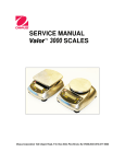
SERVICE MANUAL Valor ™ 2000 SCALES Ohaus Corporation, 7 Campus Drive, Suite 310, Parsippany, NJ 07054 (973) 377-9000 SERVICE MANUAL Valor ™ 2000 SCALES The information contained in this manual is believed to be accurate at the time of publication, but Ohaus Corporation assumes no liability arising from the use or misuse of this material. Reproduction of this material is strictly prohibited. Material in this manual is subject to change. © Copyright 2011 Ohaus Corporation, all rights reserved. TM Registered trademark of Ohaus Corporation. TABLE OF CONTENTS Page No. CHAPTER 1 GETTING STARTED 1.1 1.2 1.3 1.4 1.5 Introduction ..............................................................................................................1-1 Service Facilities ......................................................................................................1-1 Tools and Test Equipment Required ........................................................................1-1 Specifications ...........................................................................................................1-3 Scale Operation .......................................................................................................1-4 1.5.1 Overview of the Controls ...................................................................................1-4 1.5.2 Power On ..........................................................................................................1-5 1.5.3 Power Off ..........................................................................................................1-5 1.5.4 Menu Setup ......................................................................................................1-6 1.5.5 Menu Navigation ...............................................................................................1-6 1.6 Legal For Trade .......................................................................................................1-7 CHAPTER 2 TROUBLESHOOTING 2.1 2.2 Troubleshooting .......................................................................................................2-1 Diagnostic Guide ......................................................................................................2-1 2.2.1 Diagnosis ..........................................................................................................2-1 2.2.2 Checking Load Cells for Trouble .......................................................................2-2 2.2.3 Testing the Printed Circuit Board (PCB) ............................................................2-4 2.2.4 Diagnostic Guide...............................................................................................2-6 CHAPTER 3 MAINTENANCE PROCEDURES 3.1 Preventive Maintenance ...........................................................................................3-1 3.1.1 Preventive Maintenance Checklist ....................................................................3-1 3.2 Service Strategy.......................................................................................................3-1 3.3 Opening the Scale....................................................................................................3-1 3.2.1 Separating the Top and Bottom Housings .........................................................3-2 3.2.2 Removing the Component Covers and Lifting Out the Cable Plugs ..................3-3 3.4 Removing/Replacing the Main Printed Circuit Board (PCB) .....................................3-3 3.5 Replacing the Rear Display PCB..............................................................................3-4 3.6 Removing/Replacing the Load Cell ..........................................................................3-4 3.7 Cable Set Replacement ...........................................................................................3-5 3.8 Replacing the Battery ...............................................................................................3-5 3.9 Replacing the Gaskets .............................................................................................3-5 3.10 Setting/Removing Legal-For-Trade ..........................................................................3-6 3.11 Replacing the Function Label ...................................................................................3-6 CHAPTER 4 TESTING 4.1. Testing .....................................................................................................................4-1 4.1.1 Test Masses Required ......................................................................................4-1 4.2 Operational Test ......................................................................................................4-1 4.3 Segment Display Test ..............................................................................................4-1 4.4. Performance Tests ...................................................................................................4-2 4.4.1 Precision Test ...................................................................................................4-2 4.4.2 Repeatability Test .............................................................................................4-3 4.4.3 Linearity Test ....................................................................................................4-5 4.4.4 Off-Center Load Test ........................................................................................4-5 4.4.5 Adjusting Off Center Load .................................................................................4-6 Ohaus Corporation www.ohaus.com i Valor™ 2000 Series Service Manual TABLE OF CONTENTS Page No. CHAPTER 5 DRAWINGS AND PARTS LISTS 5-1 Valor 2000 Scales: Housing & Internal Parts ............................................................5-2 Appendix A STANDARD CALIBRATION A.1 Calibration ............................................................................................................... A-1 A.1.1 Span Calibration .............................................................................................. A-2 A.1.2 Linearity Calibration ......................................................................................... A-3 Appendix B SERVICE CALIBRATION B.1 Entering the Service Menu ...................................................................................... B-1 B.2 Ramp Menu ............................................................................................................ B-1 B.3 Capacity Menu ........................................................................................................ B-1 B.4 Service Unit Menu ................................................................................................... B-2 B-5 Service Span Calibration ......................................................................................... B-3 B.5 Service Linearity Calibration .................................................................................... B-4 LIST OF TABLES TABLE NO. 1-1 1-2 1-3 1-4 2-1 2-2 2-3 2-4 4-1 4-2 4-3 5-1 TITLE Page No. Specifications ......................................................................................................1-2 Functions of Display Controls ..............................................................................1-3 Battery Charge Status .........................................................................................1-4 Valor 2000 Menu Structure ..................................................................................1-5 Load Cell Resistance Readings (in Ohms) ..........................................................2-2 Color Code for Load Cell Wiring ..........................................................................2-2 Load Cell Output Readings (in mV with 5V Excitation) .........................................2-3 Diagnostic Guide .................................................................................................2-4 Test Mass Values ................................................................................................4-1 Repeatability Worksheet ......................................................................................4-4 Linearity Test Masses ..........................................................................................4-5 Valor 2000 Scales: Housing & Internal Parts .......................................................5-3 LIST OF ILLUSTRATIONS FIGURE NO. 1-1. 1-2 1-3 1-4 2-1 3-1 3-2 3-3 3-4 3-5 3-6 4-1 4-2 5-1 TITLE Valor 2000 Front Display: with controls ................................................................1-4 Waterproof seal on power input jack ....................................................................1-5 LFT Lock Switch ..................................................................................................1-7 LFT Lock Seal .....................................................................................................1-7 Valor 2000 PCB ...................................................................................................2-3 Screws and washers securing Pan Support to Top Housing ................................3-2 Scale Bottom .......................................................................................................3-2 Bolts and washers securing Load Cell to Top Housing ........................................3-2 Top and Bottom Housings with some plugs removed ..........................................3-3 Power PCB housing, next to the rechargeable battery .........................................3-5 Gasket washers seal eight receptacles in Bottom Housing ..................................3-6 Segment Display .................................................................................................4-1 Scale drawing of Valor 2000 Load Cell and Weighing Pan ..................................4-4 Valor 2000 Scales: Housing & Internal Parts .......................................................5-2 Valor™ 2000 Series Service Manual ii Ohaus Corporation www.ohaus.com CHAPTER 1 GETTING STARTED 1.1 INTRODUCTION This service manual contains the information needed to perform routine maintenance and service on the Ohaus Valor 2000 Series scales. Familiarity with the scale’s Instruction Manual is assumed. The contents of this manual are contained in five chapters: Chapter 1 Getting Started – Contains information on service facilities, tools and test equipment, specifications, and the mechanical and electronic functions of the scale. Chapter 2 Troubleshooting – Contains a diagnostic guide and error code table. Chapter 3 Maintenance Procedures – Contains preventive maintenance procedures and disassembly, repair and replacement procedures. Chapter 4 Testing – Contains a list of required test masses, an operational test, segment display test, performance tests and adjustments. Chapter 5 Drawings and Parts Lists – Contains exploded views of Valor 2000 scales identifying all serviceable components. Appendix A Standard Calibration – Explains procedures for Standard Calibration, performed prior to using a scale, and after service. Appendix B Service Calibration – Describes the Service Menu and sub-menus, which allow authorized service personnel to perform factory Linearity and Span calibrations (no pre-set limits), take Ramp readings, and to set the service menu units. 1.2 SERVICE FACILITIES To service a scale, the service area should meet the following requirements: Should be temperature controlled and meet scale specifications for temperature environmental requirements. Must be free of vibrations such as fork lift trucks close by, large motors, air currents or drafts from air conditioning/heating ducts, open windows, people walking by, fans, etc. Area must be clean and free of excessive dust. Work surface must be stable and level. Scale must not be exposed to direct sunlight or radiating heat sources. Use an approved Electro-Static Device Valor™ 2000 Series Service Manual 1-1 Ohaus Corporation www.ohaus.com CHAPTER 1 GETTING STARTED 1.3 TOOLS AND TEST EQUIPMENT REQUIRED The service shop should contain the following equipment: 1. Standard hand tools. 2. Digital Voltmeter (DVM). 3. Standard Electronics tool kit. 4. Grounding mat and clip. 5. Strain Gauge Simulator. Ohaus Corporation www.ohaus.com 1-2 Valor™ 2000 Series Service Manual CHAPTER 1 GETTING STARTED 1.4 SPECIFICATIONS Complete specifications for the Ohaus Valor 2000 Scales are listed in Table 1-2. When a scale has been serviced, it must meet the specifications listed in the table. Before servicing the scale, determine what specifications are not met. TABLE 1-1. SPECIFICATIONS Model Capacity x Readability Max x d (non-approved) V21PW3 V21PW6 V21PW15 3.0000 kg x .0005 kg 3000 g x 0.5 g 6 lb x 0.001 lb 96.00 oz x .02 oz 6.000 kg x .001 kg 6000 g x 1 g 15 lb x 0.002 lb 240.00 oz x .05 oz 15.000 kg x .002 kg 15000 g x 2 g 30 lb x 0.005 lb 480.0 oz x .1 oz 1:6000 1:7500 1:7500 3 kg x 0.001 kg 3000 g x 1 g 6 lb x 0.002 lb 96 oz x 0.05 oz 6 kg x 0.002 kg 6000 g x 2 g 15 lb x 0.005 lb 240 oz x 0.1 oz 15 kg x 0.005 kg 15000 g x 5 g 30 lb x 0.01 lb 480 oz x 0.2 oz 1:3000 1:3000 1:3000 Maximum Displayed Resolution Capacity x Readability Max x d (approved) Lo-res Displayed Resolution Linearity and Accuracy ±1d Off Center Load error ±1d Repeatability ±1d Creep (5 sec – 5 min) 1d Hysteresis 1d Zero drift vs. temp. ±1 d / oC Span drift vs. temp. ± 1d / C Zero Range ±2% of Full Scale Capacity Tare Range To Full Capacity by Subtraction beyond zero range ≤ 2 seconds Stabilization Time Overload Indication Capacity + 9d Warm-up Drift at Zero (Over 5 min) 5d max Operating Temp. range 0°to 40°C / 32°to 104°F Storage Temp. range Humidity Range -10°to 60°C / 14°to 140°F Maximum relative humidity 80 % for temperatures up to 31 °C / 88 °F, decreasing linearly to 50 % relative humidity at 40 °C / 104 °F, non condensing. Safe Overload Capacity 120% of capacity AC Power Valor™ 2000 Series Service Manual 9VDC (700mA) 1-3 Ohaus Corporation www.ohaus.com CHAPTER 1 GETTING STARTED 1.5 SCALE OPERATION This section contains information on the basic operation of the scale. 1.5.1 OVERVIEW OF THE CONTROLS Figure 1-1. Valor 2000 Front Display: with controls. (The display and LEDs are duplicated on the rear of the scale, to facilitate customer viewing.) TABLE 1-2. FUNCTIONS OF DISPLAY CONTROLS Button Zero/Tare On/Off Units Menu Yes No Primary Function (Short Press) ON/ >O/T< Turns scale ON. If scale is On: Sets zero. Performs a tare operation. UNITS Changes the weighing Unit. Secondary Function (Long Press) Off Turns scale off. Menu Enter the User menu. Menu Function (Short Press) Yes Accepts the current setting on the display. No Advances to the next menu or menu item. Rejects the current setting on the display and advances to the next available setting. Ohaus Corporation www.ohaus.com 1-4 Valor™ 2000 Series Service Manual CHAPTER 1 GETTING STARTED 1.5.2 Power ON With power applied, press On/ >O/T< /Off. All segments will appear briefly followed by Ohaus, a software revision number, and then * 0.00 g. The scale can operate on either AC Power, with the included AC adapter, or on the internal rechargeable battery. The scale automatically switches to battery operation if it is on and AC power fails. The battery must be fully charged for up to 12 hours before operation. Charge level is indicated during charging. (See Table 1-3.) The scale can be operated during charging. The battery is protected against over charging and the scale can remain connected to the AC power line. TABLE 1-3. BATTERY CHARGE STATUS Charge Status Indication Light Charge Level Off Fully Charged Flashing Green 70 – 100% Flashing Yellow 40 – 70% Flashing Red 0 – 40% Allow 20 minutes warm-up time. The scale should be calibrated before use. Note: If Auto-Off is set to ON, it must be set to OFF to allow 20 minutes warm-up time. (See Menu Setup, next page.) Note: To prevent water ingress during use, insert rubber Seal into the input jack recess. Also note that prior to use the rear adjustable feet should be opened at least a half turn. There are tiny air vents on the inside of these feet which allow the scale to “breathe,” since it is designed to be water-tight. Rear Adjustable Feet should be opened at least a half turn. 1.5.3 Figure 1-2. Waterproof seal on power input jack. Power OFF To turn the scale OFF, press and hold ON/>O/T</Off until OFF appears, then release. Valor™ 2000 Series Service Manual 1-5 Ohaus Corporation www.ohaus.com CHAPTER 1 GETTING STARTED 1.5.4 Menu Setup Programmable features of the Valor 2000 scales are contained in menus which are accessed through the Display Panel’s control switches. See the Instruction Manual for a full description of the menus and how to access them. TABLE 1-5. VALOR 2000 MENU STRUCTURE CAL rES SPAN --0-xx LIN --0-xx xx 1.5.5 UNIt A OFF Unit -kg LO HI ON OFF Unit -g 5 ON 10 OFF 15 Unit -lb ON OFF Unit -oz ON OFF FILtr AZt LO OFF O mMEd 0.5 d F HI 1 d F 3 d LFt OFF ON Menu Navigation Press and hold UNITS/Menu button until MENU is displayed, then release it. Press Yes to enter the displayed menu or press No to advance to the next menu. When viewing the menu setting, press Yes to accept the setting, or press No to change it, then press Yes to accept the setting and move to the next menu. When End is displayed, press Yes to exit the menu. Ohaus Corporation www.ohaus.com 1-6 Valor™ 2000 Series Service Manual CHAPTER 1 GETTING STARTED 1.6 LEGAL FOR TRADE When LFT is set to ON, the following menu settings cannot be accessed/changed: Calibration, Resolution, Unit, AZT, LFT. To regain access to the locked menu settings, remove the small cover on the bottom of the scale. Then during power up press and hold the recessed lock switch momentarily until zero is displayed. Figure 1-3. LFT Lock Switch. When accessing the bottom of the scale, avoid placing the scale upside down on the pan or sub-platform. Place the scale on its side. After the LFT Lock Switch has been removed, the scale must be inspected in accordance with local weights and measures regulations before it can be used in LFT mode again. Local authorities may apply a seal as shown in Figure 1-4. Figure 1-4. LFT Lock Seal. Valor™ 2000 Series Service Manual 1-7 Ohaus Corporation www.ohaus.com CHAPTER 1 GETTING STARTED Ohaus Corporation www.ohaus.com 1-8 Valor™ 2000 Series Service Manual CHAPTER 2 DIAGNOSTIC GUIDE 2.1 TROUBLESHOOTING This section of the manual contains troubleshooting information. Information is contained to isolate specific problems using Table 2-1, Diagnostic Guide. Follow all directions step by step. Make certain that the work area is clean. Handle balance components with care. Use appropriate Electro-Static Device. 2.2 DIAGNOSTIC GUIDE Table 2-1 is a Diagnostic Guide designed to help locate the problem area quickly and easily. The probable causes are listed with the most common cause first. If the first remedy does not fix the problem, proceed to the next remedy. Before attempting to repair the balance, read all chapters of this manual to be familiar with the balance components and operation. 2.2.1 Diagnosis 1 Isolate and identify the symptom 2 Refer to Table 2-1, Diagnostic Guide and locate the symptom. 3 Follow the suggested remedies in the order they appear. 4 Perform the indicated checks, or see the appropriate section of the manual. 5 Repair or replace the defective section of the balance. NOTE: If more than one symptom is observed, approach one area at a time, and remember that the symptoms may be interrelated. If a problem arises that is not covered in this manual, contact Ohaus Corporation for further information. Valor™ 2000 Series Service Manual 2-1 Ohaus Corporation www.ohaus.com CHAPTER 2 DIAGNOSTIC GUIDE 2.2.2 Checking Load Cells for Trouble 1. Perform a Resistance Test, to determine if the Load Cell is severely damaged or a short circuit to the frame has occurred. (See Chapter 4 for details.) Note: The Load Cell must be completely disconnected from the Printed Circuit Board and at no load when the resistance readings are taken. Using an ohm meter, measure and record resistance between each pair of wires from the Load Cell, as specified in Table 2-1. Compare the measured readings with the specified values in Table 2-1. If the resistance readings are in the range specified, skip to the next section. If they are outside the expected range, open circuit or short-circuit across any two wires, the Load Cell is defective: replace it. (See Chapter 3.) TABLE 2-1. LOAD CELL RESISTANCE READINGS (in Ohms) Model Ex+ to Ex– S+ to S– Ex+ to S– Ex+ to S+ Ex– to S+ Ex– to S– All models 404 ± 10 350 ± 4 289 ± 10 289 ± 10 289 ± 10 289 ± 10 2. Perform an Output Voltage Test: Measure the no load, 50% load and full load output. The reading should meet the Load Cell specifications. The Load Cell output should be very close to linear over its capacity range. NOTE: The following steps involve power applied to the scale. Load Cell solder contacts can be used as measuring points. See Figure 2-1. The EXE+ and EXE– wires should be connected to the PCB, and the SIG+ and SIG– wires must be disconnected. Record the colors for each wire connection before disconnecting. (See Table 2-2 for typical color code for Valor 2000.) TABLE 2-2. COLOR CODE FOR LOAD CELL WIRING* BLACK RED GREEN WHITE EXE– EXE+ SIG+ SIG– *Color codes may vary. – Insert the Platform Support into the Load Cell Frame, place the Platform on top, and turn on power to the scale. – Using a voltmeter, measure and record the excitation voltage supplied to the PCB: with no load on the Platform, measure the voltage across points 3 and 4 of Load Cell connection on the PCB (+EXE and –EXE). This voltage must be approximately 5.0 Volts dc with the Load cell connected. If the voltage is lower, disconnect the Load Cell cable from the PCB and measure again. If the voltage is 5 Volts dc, the Load Cell is defective and must be replaced. If the voltage remains low, the PCB is defective and must be replaced. CAUTION: IN THE NEXT STEP, DO NOT OVERLOAD THE SCALE BEYOND FULL CAPACITY RATING. Ohaus Corporation www.ohaus.com 2-2 Valor™ 2000 Series Service Manual CHAPTER 2 DIAGNOSTIC GUIDE 2.2.2 Checking Load Cells for Trouble – Measure the voltages on +SIG and –SIG wires, disconnected from PCB. Note: Measurements must be made with these wires disconnected from the PCB. These measurements represent the output of the Load Cell. Record measurements at Zero Load, 50% and full scale capacities. See Table 2-3 for typical readings. AC & Battery Connector 1 2 3 4 Rear Display PCB Connector 5 6 7 1 2 3 4 5 (Not used) 1 2 3 4 5 TOP VIEW OF PCB SIG– EXE+ EXE– SIG+ 1 2 3 4 Load Cell Figure 2-1. Valor 2000 PCB connections NOTE: Table 2-3 indicates typical readings. Actual values can vary, but should remain linear throughout the range. If readings are out of tolerance, replace the Load cell. (See Section 3.6.) TABLE 2-3. LOAD CELL OUTPUT READINGS (in mV with 5V Excitation) Model/Capacity Zero Load 50% Load 100% Load V21P3 / 3kg 0.8 ± 2.0 Zero + 3.8 Zero + 6.8 V21P6 / 6kg 0.9 ± 2.0 Zero + 4.7 Zero + 7.6 V21P15 / 15kg 0.4 ± 2.0 Zero ± 4.1 Zero ± 7.8 Valor™ 2000 Series Service Manual 2-3 Ohaus Corporation www.ohaus.com CHAPTER 2 DIAGNOSTIC GUIDE 2.2.3 Testing the Printed Circuit Board (PCB) The PCB can be tested by measuring voltages and by using a simulator. The simulator replaces the Load Cell during testing and is a useful tool for diagnosing problems. PCB Voltage Measurements Note: Prior to the voltage measurements, the battery should be fully charged and tested. 1. Disconnect power from the scale, and remove the Top housing. (See Section 3.3.1.) 2. Connect the AC Adapter to the scale and turn the scale on. 3. Using a DVM, measure the excitation voltage (EXE+ and EXE– in Figure 2-1.) The reading should be 5 volts dc. This is the excitation voltage for the Load Cell and is regulated. If the voltage is lower, replace the PCB. (See Section 3.4.) Then perform Operational Tests. (See Chapter 4.) 4. Measure incoming power from the AC Adapter Connector shown in Figure 2-1. The voltage should read between 9 and 14 volts dc with power off and above 9 Volts dc with power on. 5. Perform simulator testing. Ohaus Corporation www.ohaus.com 2-4 Valor™ 2000 Series Service Manual CHAPTER 2 DIAGNOSTIC GUIDE 2.2.3 Testing the Printed Circuit Board (PCB) Simulator Testing To perform these tests, the use of a Simulator is required. The function of a Simulator is to simulate the output of a full bridge Load Cell, allowing the scale to be separated from the Load Cell for the purposes of troubleshooting and calibration. The Load Cell used in the scale is rated at 2mV/V output with a 5 Volt excitation voltage applied. General Load Test This test checks the Main PC Board circuitry by simulating accurate Load Cell voltages at zero load, 50% and 100% load capacities. 1. Disconnect power from the scale, and remove the Top housing. (See Section 3.3.1.) Leave the Membrane Switch connected to the scale. Disconnect the battery. 2. Disconnect the Load Cell cable from the main PC Board. 3. With the Simulator set to zero, solder its cable leads to their counterparts on the PCB, using the Load Cell Cable solder points on the PCB. (See Figure 2-1.). 4. Connect a known good AC Adapter to the scale and connect to a power source. 5. Turn on the scale. An under load error may appear. This is normal. 6. Set the scale to indicate weight in kilograms (kg) and set the calibration value to maximum span value. 7. Adjust the Simulator to simulate 0% load, 50% load and 100% load for the capacity that the scale is rated for. (See Table 2.3 for values to use.) If the resulting readings are unstable, the Main PC Board is defective. 8. Use the Simulator to calibrate the scale in the next procedure to verify if the Main PC Board is good or bad. Calibration Test This test calibrates the scale using the simulator and can verify that the Main PC Board is functioning properly or improperly. 1. With the scale on, enter the scale menu and perform a span calibration. (See Appendix A.) 2. Follow the scale prompts. When the scale indicates a given weight to be placed on the scale, set the simulator to an equivalent value based on Table 2-3. 3. Upon completion of calibration, the PCB can be further checked using the Simulator to simulate various weight values. If simulator settings and weight readings on the scale agree, the PCB is functional. If the scale readings vary, or do not agree with readings in Table 2-3, the Main PC Board is defective and should be replaced. (See Chapter 3.) Valor™ 2000 Series Service Manual 2-5 Ohaus Corporation www.ohaus.com CHAPTER 2 DIAGNOSTIC GUIDE 2.2.4 Diagnostic Guide TABLE 2-4. DIAGNOSTIC GUIDE Symptom Possible Cause Remedy Unstable weight Air flow may be blocked to scale because rear feet are tightened completely. Adjust rear feet at least slightly to allow proper air flow. (They should be tightened when scale is washed.) ----- Busy message Displayed while zero or tare function is in process --C-- Busy message Displayed while calibration data is being collected. CLEAr PAN Clear pan message Weight reading exceeds zero limit. Remove load from scale. dONE Done message Calibration process is completed. -OFF- Off message Scale is turning off. -NO- No message Requested action is not allowed. loBat Low Battery Battery charge is too low. Recharge battery. CAL E Calibration Error Calibration point value is outside of acceptable range. (See Appendix A or B.) Err 1 Error 1: Overload limit exceeded Weight reading exceeds capacity plus 9d. Remove load from scale. Recalibrate scale. Err 2 Error 2: Underload limit exceeded Weight reading is below calibration zero value by 30% of scale capacity. Add load to scale. Recalibrate scale. Err 9 Error 9: Menu data checksum error Menu data in EEPROM is corrupted. Cycle power on and off. If error continues, check menu settings. If problem continues, replace PCB. Err14 Error 14: Initial Zero limit error Weight reading exceeds 10% Power On Zero limit when LFT is set to ON. Place platform on the balance. If the problem continues, add a small amount of weight at power on. If the problem persists, perform span and linearity calibration from Service menu. (See Appendix B.) Ohaus Corporation www.ohaus.com 2-6 Valor™ 2000 Series Service Manual CHAPTER 3 MAINTENANCE PROCEDURES 3.1 PREVENTIVE MAINTENANCE Ohaus scales are precision instruments and should be carefully handled, stored in a clean, dry, dust-free area, and cleaned periodically. Follow these precautionary steps: – When a scale has had chemicals or liquids spilled on it, all exterior surfaces should be cleaned as soon as possible with warm water on a damp cloth. – Do not leave a mass on the scale when the scale is not in use. – Allow time for the scale to stabilize after moving it from an area which is at a different temperature than the area where it is to be operated. Allow one hour for each 5°F (2.7°C) temperature change before using the scale. After temperature stabilization, allow an additional 20 minutes after turning the scale on, for the scale electronics to stabilize. 3.1.1 Preventive Maintenance Checklist The scale should be inspected and checked regularly, as follows: 1. Remove the Pan and Sub Pan to inspect and clean the area beneath the Pan. 2. Clean the outside of the scale using a damp cloth with warm water. CAUTION DO NOT USE CHEMICAL CLEANERS OR SOLVENTS OF ANY TYPE. SOME CLEANERS ARE ABRASIVE AND MAY AFFECT THE SCALE’S FINISH. 3. Check the Power Cord for broken or damaged insulation. 4. If using the rechargeable battery and the scale malfunctions, first recharge the battery to see if this resolves the problem. 5. Make a visual inspection for faulty connectors, wiring, and loose hardware. 3.2 SERVICE STRATEGY All parts of the Valor 2000 or designed to be replaced rather than repaired. This includes the Main Printed Circuit Board (PCB), the Rear Display PCB, the Load Cell, the Power PCB, the Rechargeable Battery, and the cables that connect them. For an illustrated list of replaceable parts, see Chapter 5. 3.3 OPENING THE SCALE Use these procedures in order to replace the Load Cell, Battery, any of the Printed Circuit Boards, and/or LCD Displays. Valor™ 2000 Series Service Manual 3-1 Ohaus Corporation www.ohaus.com CHAPTER 3 MAINTENANCE PROCEDURES 3.3.1 Separating the Top and Bottom Housings Common hand tools are sufficient to disassemble the Valor 2000 scales. Turn the scale off and unplug the power cord before you begin. 1. Lift off the Weighing Pan from the Pan Support. 2. Remove the Pan Support: by removing the bolts and washers that secure it to the Load Cell and then lift it off. Check if the washers need to be replaced due to corrosion of the rubber inside lining. Figure 3-1. Bolts and washers securing Pan Support to Top Housing. 3. Turn the scale over. Remove the two screws that secure the LFT Lock Switch Cover, and lift it off. Screws and washers that secure the Housing 4. Remove the eight screws holding the Housing in place. (See Figure 3-1.) Note: six of the screws are long; the two that secure the front of the scale are short. 5. Carefully separate the Top Housing from the Bottom Housing. (There may be some resistance caused by the Seal Gasket.) Avoid straining the cable set that connects the Main PCB in the top housing to the Power PCB in the bottom housing. Water seal for power input jack LFT Lock Switch Figure 3-2. Scale Bottom. 6. Lay the two housings close to each other, so the PCB cable is not strained. 7. Remove cable plugs, component covers, and screws holding cables to the Housing. 8. Lift out Seal Gasket. Set it aside. 9. To remove the Load Cell, carefully turn the scale over and remove the two bolts and washers that secure the Load Cell to the Top Housing. Check if the washers need to be replaced due to corrosion of the rubber inside lining. Hold the Load Cell from underneath so it doesn’t fall when the bolts are removed. Ohaus Corporation www.ohaus.com 3-2 Figure 3-3. Bolts and washers securing Load Cell to Top Housing. Valor™ 2000 Series Service Manual CHAPTER 3 MAINTENANCE PROCEDURES 3.3.2 Removing the Component Covers and Lifting Out the Cable Plugs Main PCB Cover Load Cell Cover Rear Display PCB Cover Power PCB Cover Figure 3-4. Top and Bottom Housings with some plugs removed. 1. Remove the screws that secure the cables to the housing, to avoid straining the cables when loosening the plugs. 2. Firmly grasp the plugs and lift them clear of the component covers. (Don’t try to remove them completely until they are disconnected from the PCBs.) 3. Remove the screws that secure the component covers to the housing. The PCB covers on the Top Housing must be removed before the Load Cell Cover, to allow it to clear. Only remove the Power Supply Cover if the Power PCB is to be replaced. 3.4 Removing/Replacing the Main Printed Circuit Board (PCB) The Main PCB must be removed in order to replace the Load Cell, since the Load Cell Cable is soldered to the Main PCB. First be sure the eight screws securing the PCB Cover have been removed and that the cable plugs have been lifted out. Then proceed as follows: 1. Pull the two white Cable Tabs that connect the Main PCB to the Power PCB and the Rear Display PCB. (It is necessary to hold the PCB Cover by hand at an angle while pulling the Cable Tabs. Once the Cable Tabs are freed, the PCB Cover can rest slightly away from the PCB, allowing access to the screws that hold the PCB in place.) 2. Remove the four screws that hold the PCB in place. (It is necessary to hold the screwdriver at an angle in order to access the screw heads.) 3. If either the Main PCB or the Load Cell is to be replaced, unsolder the Load Cell Cable from the Main PCB at the four solder points on the PCB. 4. When replacing the Main PCB, solder the Load Cell Cable leads to the solder points on the PCB. Note the connection order from left to right: red, black, green, white. 5. To reinstall the Main PCB after soldering the Load Cell leads, position the PCB on an angle in its housing, insert the four screws and tighten them. 6. Re-seat the white plastic Cable Tabs connecting the Power PCB and the Rear Display PCB to the Main PCB. 7. Position the PCB Cover over the screw holes, insert the eight screws and tighten them. 8. Re-insert the Cable Plugs in the PCB Cover. Valor™ 2000 Series Service Manual 3-3 Ohaus Corporation www.ohaus.com CHAPTER 3 MAINTENANCE PROCEDURES 3.5 Replacing the Rear Display PCB First be sure the eight screws securing the PCB Cover have been removed and that the cable plug has been lifted out. Then proceed as follows: 1. Pull the white Cable Tab that connects the Rear PCB to the Main PCB. 2. Remove the two screws that hold the PCB in place. 3. Lift out the PCB and position its replacement over the screw holes in the housing. Insert the four screws and tighten them. 4. Re-seat the white plastic Cable Tab connecting the Main PCB to the Rear Display PCB. 5. Position the PCB Cover over the screw holes, insert the four screws and tighten them. 6. Re-insert the Cable Plugs in the PCB Cover. 3.6 Removing/Replacing the Load Cell The Load Cell may need to be replaced because of balance instability, or because the balance does not calibrate or repeat, or because it is physically broken or displays an error code. Note: There is no need to disassemble the Load Cell. It is supplied as an assembled unit. (See Chapter 5 for parts information.) 1. Remove the two bolts in the Top Housing that secure the Load Cell. 2. Be sure the six screws securing the Load Cell Cover have been removed and that the Cable Plugs have been lifted out. 3. Gently lift the Load Cell away from the housing. 4. If the Load Cell is to be replaced, or the off-center load adjusted, unsolder the Load Cell Cable from the Main PCB, in order to completely remove the Load Cell from the housing. 5. When installing the replacement Load Cell, first insert and tighten the two bolts in the Top Housing. Then re-solder the Load Cell Cable to the Main PCB. Then insert and tighten the six screws that secure the Load Cell Cover. Note: There is no need to remove the bolts in the metal bracket surrounding the Load Cell, unless it is necessary to adjust the Up/Down Stops. Ohaus Corporation www.ohaus.com 3-4 Valor™ 2000 Series Service Manual CHAPTER 3 MAINTENANCE PROCEDURES 3.7 Removing/Replacing the Power Supply PCB The Valor 2000’s power supply is located in the Power PCB Housing. To replace it: 1. Remove the four screws in its cover. 2. Lift the cover as much as possible to access and remove the white tabs holding the two cable sets to the PCB. 3. Remove the screw holding a metal stop tab that secures the PCB; lift them out. 4. Slide the Power PCB up and out. 5. Slide in the replacement PCB. 6. Insert the two cable plugs. Figure 3-5. Power PCB housing, next to the rechargeable battery. 7. Position the Power PCB cover and install the screws 3.8 Cable Set Replacement Note: All the cables – connecting the Main and Rear Display PCBs, connecting the Main PCB to the Power PCB, and the Power PCB to the Battery – are sold together with their plugs as a single set. Replace them singly or together, as follows: 1. Disconnect the cables from the connectors and remove the quick-connect tabs. 2. Note that the new cable set does NOT come with quick-connect tabs – insert the replacement wire in the new quick-connect tabs acquired separately. 3. Reconnect the wires, using the original plastic tabs. 3.9 Replacing the Battery – Charge the battery only with the scale’s charger. Charging it under any other conditions may cause it to overheat, emit hydrogen gas, leak, ignite or burst. – Operate the battery at normal temperature range as specified for the scale. – Do NOT short the battery terminals under any conditions. – Do NOT dispose of the battery in incinerators, or crush or try to open it. Dispose of the defective battery in accordance with local regulations. – Check the battery for any irregularities in appearance. If there is any damage to the case such as cracks, deformation or leakage, replace it. – Do NOT charge the battery with the charger terminals reversed: ONLY connect red cables to red (positive) terminals and black to black (negative). 1. Remove the two screws from the battery bracket, and lift out the bracket. 2. Carefully lift out the battery – avoid straining the cables. 3. Pull the quick-connect tabs free of the battery, and reinstall them in the new battery. 4. Set the replacement battery and a bracket on top of it, and install the two screws. Valor™ 2000 Series Service Manual 3-5 Ohaus Corporation www.ohaus.com CHAPTER 3 MAINTENANCE PROCEDURES 3.10 Replacing the Gaskets The Main Gasket that seals the opening between the two housings may need to be replaced because of wear or corrosion. This may also be true of the small gasket-washers that seal the screw holes in the Bottom Housing, the Load Cell Seal Gasket (also called the Bellows Gasket), and the metal seal washers for the bolts that secure the Pan Support and Load Cell on the Top Housing. They are sold as a set. The Main Gasket fits snugly on the lip of the Bottom Housing. Install it there first. Then the Top Housing will fit correctly when the two housings are put together. Note: Remember to install the Main Gasket before reconnecting the cable that links the Power PCB to the Main PCB. Install the Load Cell Seal Gasket very carefully (to avoid tearing or stretching it) over the opening in the Top Housing, before installing the Pan Support. Note the placement of the gasket-washers, as shown in Figure 3.4: Gasket washers seal screw holes in the Bottom Housing Figure 3.6. Gasket washers seal eight receptacles in Bottom Housing. Ohaus Corporation www.ohaus.com 3-6 Valor™ 2000 Series Service Manual CHAPTER 3 MAINTENANCE PROCEDURES 3.10 Setting/Removing Legal-For-Trade The Valor 2000 can be used in Legal-For-Trade (LFT) mode, after being inspected and sealed in accordance with local weights and measures or approval agency regulations. If the scale is serviced and the LFT seal is broken, it must be re-inspected and re-sealed to be used again in Legal-For-Trade mode. Note: In LFT mode, the following menus and settings are not accessible: Calibration, Resolution, Unit, AZT, LFT. To take the scale out of LFT mode, break the mechanical seal, remove the small cover on the bottom of the scale. Then, during power-up, press and hold the recessed LFT Lock Switch on the Bottom Housing. All menus will then be accessible. LFT mode is set through a series of menu settings and a hardware “LFT switch” located on the Bottom Housing. (Access to this switch may be denied using additional mechanical methods, by local weights and measures or approval agency.) Follow these steps to set the scale for LFT mode: 1. Calibrate the scale. (See Appendix A.) 2. To access the Service Menu, press and hold UNITS/Menu until MENU appears, then release it. Press Yes. Then press No continuously until LFT appears. Press Yes. Press No until End appears. Then press Yes to return to weighing mode. 3. Re-install the LFT Lock Switch Cover. 3.9 Replacing the Function Label The Function Label may need to be replaced, either due to corrosion or wear. (See Chapter 5 for parts lists.) Use a broad knife to remove the label. Clean the glue residue from the Housing surface. Then carefully place the new label where the old one was. Valor™ 2000 Series Service Manual 3-7 Ohaus Corporation www.ohaus.com CHAPTER 3 MAINTENANCE PROCEDURES Ohaus Corporation www.ohaus.com 3-8 Valor™ 2000 Series Service Manual CHAPTER 4 TESTING 4.1 TESTING Before and after servicing a Valor 2000 scale, an operational test and various performance tests should be made to confirm that the scale meets specifications. Turn the scale on and allow it to warm up for at least one hour before performing these tests. NOTE: Make sure the test area is free from drafts and that the scale rests on a level and vibration-free surface. 4.1.1 TEST MASSES REQUIRED The masses required to test the Ohaus Valor 2000 scales must meet the requirements of ASTM Class 4 or OIML F2 Tolerance. The mass values are listed in Table 4-1. TABLE 4-1. TEST MASS VALUES Model Calibration Weight (kg) 4.2 V21PW3 V21PW6 V21PW15 1, 2, 3 2, 4, 6 5, 10, 15 Operational Test 1. Connect a functioning Power Adapter to the scale power receptacle located on the bottom of the scale. 2. Plug the Power Cord into a suitable power source, or power the scale on using battery power. (Assure that the battery is charged beforehand.) 4.3 Segment Display Test Turn the scale on, and ensure that all segments are enabled and displayed briefly. The scale’s model number appears next, followed by a software revision number. This is a Segment Display Test. (See Figure 4-1.) Figure 4-1. Segment Display Valor™ 2000 Series Service Manual 4-1 Ohaus Corporation www.ohaus.com CHAPTER 4 TESTING 4.4 Performance Tests Accurate performance of the Valor 2000 scales is determined by a series of four performance tests. The displayed readings are compared with the tolerances listed for each test in Table 1-2. Tolerance values are expressed in counts. A one-count difference is shown in the last digit on the scale display. NOTE: The following performance tests are used to evaluate scale operation before and after repairs. The scale must meet the requirements specified in each test as well as the other specifications listed in Table 1-2. Before proceeding with the following tests, the scale should be calibrated. (See Appendix A and B.) 4.4.1 Precision Test The Precision Test measures the Standard Deviation of a set of similar weight readings, which should match the specification for each model, listed in Table 1-1. 1. Power on the balance. The reading on the display should be 0g. 2. Select a mass weighing near the maximum capacity of the balance, and place it on the center of the Pan. Observe and record the reading. 3. Remove the mass. The reading should return to 0g ±1 count. 4. Repeat this test three times. The reading should be within ±1 count of the reading recorded. If so, the balance passes the Precision Test. 5. If the deviation for any set of readings (using the same mass placed on the center of the Pan) is greater than ±1 d, the balance does not meet the precision specification. Inspect and correct the following areas: – Check for mechanical obstructions. Any foreign object touching any part of the moving assemblies will cause a balance to fail the Precision Test. Inspect and correct as necessary. – If the scale does not meet specifications, move it to a suitable location, ensure that it is level, and try again. If it still does not meet specifications, perform a service calibration, and try again. (See Appendix B for Service Calibration.) Ohaus Corporation www.ohaus.com 4-2 Valor™ 2000 Series Service Manual CHAPTER 4 TESTING 4.4.2 Repeatability Test Repeatability is the Standard Deviation of a set of similar weight readings. Requirements: – To perform this test a single mass must be used for all readings. – The test mass should be approximately ½ of the capacity of the instrument. – Wear gloves when handling the mass. Before starting a repeatability test, set up the instrument as follows: Set Up: Enter the menu and adjust and record the following settings: A. Set the Filter level to medium or the center of its range. B. Set the AZT (Auto Zero Tracking) to .5d or its lowest setting. Do not turn it off. C. Set the instrument to display the same units as the performance specifications. Record Settings: Filter Level Setting = ____________ Auto Zero Tracking Setting = ____________ Displayed Units = ____________ Mass Used = ____________ TEST PROCEDURE: 1. Zero the instrument. 2. Using a test mass approximately half the capacity of the instrument, place the mass on the center of platform. Record the reading on the worksheet provided. 3. Remove the mass from the platform. 4. Repeat this test starting at Step 1 until you record a total of ten readings Fill in the worksheet (Table 4-2) with the ten (10) readings. Valor™ 2000 Series Service Manual 4-3 Ohaus Corporation www.ohaus.com CHAPTER 4 TESTING 4.4.2 Repeatability Test TABLE 4-2. REPEATABILITY WORKSHEET n Reading Delta = Reading – Mean Delta x Delta 1 2 3 4 5 6 7 8 9 10 n = number of Reading Mean = Sum of readings / 10 Delta = Reading – Mean Standard Deviation = Square Root of (sum of (Delta x Delta) / 9) 5. Add the ten readings and divide the total by 10 to find the Mean (average). 6. Mean = (Reading 1 + Reading 2 + Reading 3 + Reading 4 + Reading 5 7. + Reading 6 + Reading 7+ Reading 8 + Reading 9 + Reading 10) / 10 Mean =________ 6. Calculate the Delta for each reading and record in the work sheet. Delta = Reading – Mean 7. Calculate the Delta x Delta for each reading and record in worksheet. 8. Add the ten Delta x Delta values and divide by 9 9. Calculate the Standard Deviation by applying the square root of the result from step 8. Standard Deviation =___________ Note: If the balance does not meet specifications, move it to a suitable location, ensure that it is level, and try again. If it still does not meet specifications, perform a service calibration, and try again. (See Appendix B for Service Calibration.) Ohaus Corporation www.ohaus.com 4-4 Valor™ 2000 Series Service Manual CHAPTER 4 TESTING 4.4.3 Linearity Test This test is used to determine the linearity of the unit throughout its operating range. The masses used to perform this test can be utility masses NOTE: The scale must pass the Precision and Repeatability Tests, and be calibrated before the Linearity Test may be performed. TABLE 4-3. LINEARITY TEST MASSES Capacity (g) 3000 x .5g 6000 x 1g 15000 x 2g Reference Wt. 750 1500 3000 Load 1 750 1500 3000 Load 2 1500 3000 9000 Load 3 2250 4500 12000 NOTE: All masses are nominal values. Use the same reference mass throughout the procedure. 1. Place the test mass on the Scale, record the weight and remove. 2. Place Load 1 on the Scale and press ON/ >O/T<. 3. Place the test mass on the Scale, record the weight and remove. 4. Place Load 2 on the Scale and press ON/ >O/T<. 5. Place the test mass on the Scale, record the weight and remove. 6. Place Load 3 on the Scale and press ON/ >O/T<. 7. Place the test mass on the Scale and record the weight. 8. The difference in the weights of the test mass should be within ±1 d. If not, calibrate (see Appendix A.1) and repeat the test. 9. If the Scale remains out of tolerance, the Load Cell may need to be replaced. 4.4.4 Off-Center Load Test The Off-Center Load Test is used to determine whether displayed weight values are affected by moving the sample to different areas of the Pan. 1. Place half of the scale’s capacity in the center of the Pan. 2. Note the reading. 3. Move the mass halfway (between the center and the edge) to the front of the Pan. Note any differences in the displayed weight reading. 4. Repeat the test for the back, left, and right position of the Pan. 5. Maximum allowable change in displayed weight readings for each of the four positions can be found in Tables 1-2 (Specifications, page 1-3). If this maximum is exceeded, follow procedures in Section 4.4.5, Adjusting Off Center Load. Valor™ 2000 Series Service Manual 4-5 Ohaus Corporation www.ohaus.com CHAPTER 4 TESTING 4.4.5 Adjusting Off Center Load If the Off Center Load (OCL) is excessive, perform adjustment as follows: Top view of Load Cell Side view of Load Cell Weighing Pan’s center, with points A – D indicated 2 3 1 4 Figure 4-2. Scale drawing of Valor 2000 Load Cell and Weighing Pan. 1. Place the test weight in the center of the Weighing Pan. 2. Tare the balance. 3. Move the weight to point A and record the reading. 4. Move the weight to point B and record the reading. 5. Move the weight to point C and record the reading. 6. Move the weight to point D and record the reading. 7. If the reading at point A is negative, file at points 1 and 4 AT AN ANGLE. 8. If the reading at point B is negative, file at points 1 and 2 STRAIGHT ACROSS. 9. If the reading at point C is negative, file at points 2 and 3 AT AN ANGLE. 10. If the reading at point D is negative, file at points 3 and 4 STRAIGHT ACROSS. Note: It is not recommended that you try to adjust more than –5 counts if the beam has been filed already. If the beam has not been filed previously, you can adjust –10 counts. Remember, when filing you are weakening the beam. File a little at a time. Ohaus Corporation www.ohaus.com 4-6 Valor™ 2000 Series Service Manual CHAPTER 5 PARTS LISTS & DIAGRAMS This section of the manual contains exploded views of the Valor 2000 scales. The exploded view drawings are designed to identify the parts which can be serviced on the scale in the field. NOTE: In all cases where a part is replaced, the scale must be thoroughly checked after the replacement is made. The scale MUST meet the parameters of all applicable specifications in this manual. If further technical information is needed, please contact your local Ohaus distributor, or: Ohaus Corporation, www.ohaus.com 7 Campus Drive Suite 310 Parsippany, NJ 07054 USA Tel: 973-377-9000 Fax: 973-593-0359 In the United States call toll free, 800-526-0659 between 8:00 a.m. and 6:00 p.m. EST. Valor™ 2000 Series Service Manual 5-1 Ohaus Corporation www.ohaus.com CHAPTER 5 PARTS LISTS & DIAGRAMS 5.1 VALOR 2000 SCALES: HOUSING & INTERNAL PARTS 1 16 2 3 4 8 12 5 9 3 6 14 80 15 10 3 18 7 13 17 3 16 11 Figure 5-1. Valor 2000 Scales: Housing & Internal Parts. Ohaus Corporation www.ohaus.com 5-2 Valor™ 2000 Series Service Manual CHAPTER 5 PARTS LISTS & DIAGRAMS 5.1 VALOR 2000 SCALES: HOUSING & INTERNAL PARTS TABLE 5-1. VALOR 2000 SCALES: HOUSING & INTERNAL PARTS Drawing Item Description 1 Pan 2 Pan Support 3 Gasket Kit: Main Gasket, Load Cell Seal Gasket, and Gasket Washers 4 Function Label 5 Housing, Top 6 Load Cell Assembly 7 Housing, Bottom 8 Main PCB, with LED 9 Back Display PCB, with LED 10 Power PCB 11 Feet, 4, Adjustable 12 Back Overlay 13 Cable Set, 3 14 Battery Bracket 15 Battery, Rechargeable 16 Hardware Kit 17 LFT Sealing Kit 18 Level Bubble 80 Adapter Note: The Parts List is identical for all Valor 2000 models. For parts numbers, see your local Ohaus distributor, or visit www. Ohaus.com. Valor™ 2000 Series Service Manual 5-3 Ohaus Corporation www.ohaus.com CHAPTER 5 PARTS LISTS & DIAGRAMS Ohaus Corporation www.ohaus.com 5-4 Valor™ 2000 Series Service Manual APPENDIX A STANDARD CALIBRATION APPENDIX A. STANDARD CALIBRATION A.1 CALIBRATION Standard calibration should be performed prior to using a scale, and after service. See Section 4.2 for Calibration Masses required for each model. Note: Be careful not to touch the scale or the table while calibration is in progress, as it will cause the process to fail. Preliminary Steps: 1. Be sure the scale is level and stable during the entire calibration process. 2. If LFT is set to On, calibration is unavailable. To set LFT to OFF, see Section 1.10, page 1-19. Note: To use the LFT mode again after turning it off, it is necessary to have the scale locked and sealed by local Weights and Measures authorities. 3. Allow the scale to warm up for approximately 20 minutes after stabilizing to room temperature. 4. To abort calibration, press the Exit button anytime during the calibration process. Valor™ 2000 Series Service Manual A-1 Ohaus Corporation www.ohaus.com APPENDIX A STANDARD CALIBRATION A.1.1 Span Calibration Span calibration uses two calibration points. The first is established with no load on the scale. The second is established at a load from the Span Calibration Point values in Table 1-1. The span calibration point is user selectable. To enter the Calibration menu, press and hold UNIT/Menu until CAL appears. Press Yes. SPAN appears. Press YES. CAL spaN 0 flashes. The kg LED is lit to indicate the calibration unit. With no weight on the pan, press Yes to establish the zero point. The zero calibration value must be stable and within 20% of the stored factory zero calibration value. Note: Outlined characters represent a flashing display. Note: If the pan is not empty (20% of the factory calibration zero value), CLEAr PAN flashes for a timeout period of five seconds. If the load is not stable within ten seconds, or the value is not within the 20% limit, CAL E appears for three seconds and the scale returns to the weighing mode. The previous user calibration data is used and the current weight is displayed. CLEAr PAN CAL E --C-- - - C - - appears while the zero point is established. The span calibration point flashes. Place the specified calibration weight on the pan and press Yes. To choose a different span point, press No until the desired value appears. (See the User Calibration Point Table for available span points.) The alternate span points are displayed in decreasing order. Place the specified calibration weight on the pan and press Yes. - -C - - flashes while the span point is established. If span calibration was successful, dONE appears for 1.5 seconds. Then the scale exits to the weighing mode and displays the actual weight value. (The example shows a 2 kg span weight on the pan.) Note: Calibration may be aborted at any time by turning the scale off. --C-dONE 2.000 -OFF- NOTE: If calibration fails, ensure that the test area is free from drafts and the surface the scale rests on is level and free of vibrations. Then try to calibrate again. If it continues to fail, there may be an internal problem. To resolve internal problems, follow procedures in Chapter 3. Ohaus Corporation www.ohaus.com A-2 Valor™ 2000 Series Service Manual APPENDIX A STANDARD CALIBRATION A.1.2 Linearity Calibration Linearity calibration uses three calibration points. The first is established with no load on the scale. The second and third are established at mid-capacity and full capacity. (See Table 4-3.) To enter the Calibration menu, press and hold UNIT/Menu until CAL appears. Press Yes. SPAN appears. Press No. LINEAr appears. Press YES. CAL lIN 0 flashes. The kg LED is lit to indicate the calibration unit. With no weight on the pan, press Yes to establish the zero point. (Outlined characters represent a flashing display.) Note: If the pan is not empty (20% of the factory calibration zero value), CLEAr PAN flashes for a timeout period of five seconds. If the load is not stable within ten seconds, or the value is not within the 20% limit, CAL E appears for three seconds and the scale returns to the weighing mode. The previous user calibration data is used and the current weight is displayed. CLEAr PAN CAL E - - C - - appears while the zero point is established. --C-- The mid calibration point value flashes. Place the specified calibration weight on the pan and press Yes. (The example shows the mid calibration point value for a scale capacity of 3 kg. Note: The new mid calibration value must be stable and within 5% of the stored factory mid calibration value. If the load is not stable within 10 seconds, or the value is not within the 5% limit, CAL E flashes for three seconds and the scale returns to the weighing mode and the currently active unit of measure. The previous user calibration data is used and the current weight is displayed. CAL E - -C - - flashes while the mid point is established. --C-- The full calibration point value flashes. Place the specified calibration weight on the pan and press Yes. (The example shows the full calibration point value for a Scale Capacity of 3 kg.) - - C - - flasheswhile the full point is established. If linearity calibration was successful, dONE appears for 1.5 seconds. The scale exits to the weighing mode and displays the actual weight value in the currently active unit of measure. (The example shows the WEIGH mode with the 3 kg linearity weight on the pan.) Valor™ 2000 Series Service Manual A-3 --C-dONE 3.000 Ohaus Corporation www.ohaus.com APPENDIX A STANDARD CALIBRATION Ohaus Corporation www.ohaus.com A-4 Valor™ 2000 Series Service Manual APPENDIX B SERVICE CALIBRATION APPENDIX B. SERVICE CALIBRATION This section describes the Service Menu and sub-menus, which allow authorized service personnel to perform factory Linearity and Span calibrations (no pre-set limits). Note: Be careful not to touch the scale or the surface it rests on while calibration is in progress, as it will cause the process to fail. B.1 Entering the Service Menu Turn the scale off. Press and hold ON >O/T< / Off and UNIT / Menu for 10 seconds until SErVC appears. B.2 Ramp Menu When S.rAMP appears, press YES to accept the Ramp menu, or NO to advance to the Service Calibration menu item. SErVC S.rAmMP The ramp display shows the percentage of use of the A to D circuit, that is, of the temperature-compensated duty cycle. The actual value is not as important as how it changes. – It should increase as the weight on the scale is increased. – The ramp display should remain constant without fluctuations. If you press Yes to select Ramp, a number appears. It should be constant. Add masses from minimum to maximum capacity. The reading will increase, but should not fluctuate. 0.0 The Ramp value is displayed as a percent of the A/D range. Press YES to advance to the Capacity menu item. Press NO to exit to the weighing mode. to Note: Ramp is used to troubleshoot load cell problems. 0% represents no signal from the A/D, 100% reflects the upper signal range of the A/D. B.3 Capacity Menu When S.CAP appears, press YES to accept the Capacity menu item, or press NO to advance to the Unit menu item. 100.0 S.CAP The current Capacity Setting is displayed, blinking. (Outlined characters represent a flashing display.) Note: The available settings are 3, 6, and 15. The default setting is 3. Press NO to step through the settings. Press YES to accept the setting and move to the Service Unit menu item. Valor™ 2000 Series Service Manual B-1 Ohaus Corporation www.ohaus.com APPENDIX B SERVICE CALIBRATION B.4 Service Unit Menu When S.UNIt appears, press YES to accept the Service Unit menu item, or NO to advance to the Service Calibration menu item. When S.UNIt appears and the kg LED is lit, press YES to accept the kg menu item, or NO to advance to the Gram Unit menu item. S.UNIt S.Unit The Kilogram Unit menu item setting appears, blinking. The available settings are Off and On. The default is On for all models. Press NO to step through the settings. Press YES to accept the setting and move to the Gram Unit menu item. When S.UNIt appears and the g LED g is lit, press YES to accept the Gram Unit menu item, or NO to advance to the Pound Unit menu item. S.Unit The Gram Unit menu item setting appears, blinking. The available settings are Off and On. The default is On. Press NO to step through the settings. Press YES to accept the setting and move to the Pound Unit menu item. When S.UNIt appears and the lb LED is lit, press YES to accept the Pound Unit menu item, or NO to advance to the Ounce Unit menu item. S.Unit The Pound Unit menu item setting appears, blinking. The available settings are Off and On. The default is On. Press NO to step through the settings. Press YES to accept the setting and move to the Ounce Unit menu item. When S.UNIt appears and the oz LED is lit, press YES to accept the Ounce Unit menu item, or NO to advance to the Service Unit menu item. S.Unit The Ounce Unit menu item setting appears, blinking. The available settings are Off and On. The default is On. Press NO to step through the settings. Press YES to accept the setting and move to the Service Calibration menu. Ohaus Corporation www.ohaus.com B-2 Valor™ 2000 Series Service Manual APPENDIX B SERVICE CALIBRATION B.5 Service Span Calibration When S.CAL appears, press YES to accept the Service Calibration menu, or NO to advance to the End sub-menu selection. When S.SPAN appears, press YES to accept the Service Span Calibration menu or No to advance to the Service Linearity Calibration menu. S.CAL S.SPAN 0 flashes. With no weight on the pan, press Yes to establish the zero point. (Outlined characters represent a flashing display.) --C-- - - C - - flashes while the zero point is established. Service Span Calibration point flashes. (The example shows the value for a Scale Capacity of 3 kg.) Place the specified calibration weight on the pan and press Yes. --C-- - - C - - flashes while the span point is established. If span calibration was successful, the actual weight reading appears for three seconds, followed by the Service Linearity Calibration menu item. (The example shows a 3 kg span weight on the pan.) Valor™ 2000 Series Service Manual B-3 3.000 Ohaus Corporation www.ohaus.com APPENDIX B SERVICE CALIBRATION B.6 Service Linearity Calibration This calibration method uses three points. The full-calibration point is established with a weight on the scale. The mid-calibration point is established with a weight equal to half of the full calibration weight on the scale. The zero calibration point is established with no weight on the scale. The mid-calibration points cannot be altered by the user during the calibration procedure. When S.LIN appears, press YES to accept the Service Linearity Calibration menu, or No to advance to the End menu item. S.LIN 0 flashes. The kg LED is lit to indicate the calibration unit. With no weight on the pan, press Yes to establish the zero point. (Outlined characters represent a flashing display.) --C-- - - C - - flashes while the zero point is established. The mid calibration point value flashes. The kg LED is lit to indicate the calibration unit. (The example shows the mid calibration point value for a Scale Capacity of 3 kg.) Place the specified calibration weight on the pan and press Yes. --C-- - - C - - flashes while the mid point is established. The full calibration point value flashes. The kg LED is lit to indicate the calibration unit. (The example shows the full calibration point value for a Scale Capacity of 3 kg.) Place the specified calibration weight on the pan and press Yes. - - C - - flashes while the full point is established. If linearity calibration was successful, the actual weight reading appears for three seconds, followed by the S.End menu item. (The example shows a 3 kg span weight on the pan.) If linearity calibration was successful, S.End appears. Press YES to exit the Service menu and return to the weighing mode, or NO to return to the first Service menu item. --C-3.000 S.End NOTE: If calibration fails, ensure that the test area is free from drafts and the surface the scale rests on is level and free of vibrations. Then try to calibrate again. If it continues to fail, there may be an internal problem. To resolve internal problems, follow procedures in Chapter 3. Ohaus Corporation www.ohaus.com B-4 Valor™ 2000 Series Service Manual *80252589* P/N 80252589B SERVICE MANUAL: Valor 2000 SERIES SCALES