1
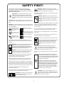
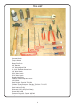
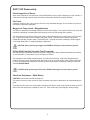
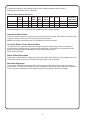
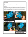
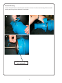
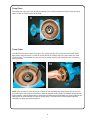
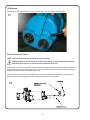
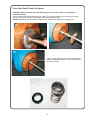
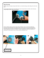
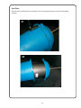
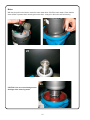
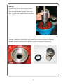
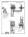
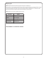
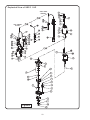
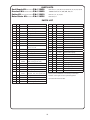
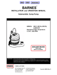
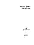
®
BARNES
SERVICE MANUAL
SGPC 1 HP Pump
Models Effected:
SGPC10S4L
SGPC10S4AUE
SGPC10S4AUF
ultra
IMPORTANT!
A Crane Co. Company
TM
Read all instructions in this manual before operating pump.
As a result of Crane Pumps & Systems, Inc., constant product improvement program,
product changes may occur. As such Crane Pumps & Systems reserves the right to
change product without prior written notification.
420 Third Street
Piqua, Ohio 45356
Phone: (937) 778-8947
Fax: (937) 773-7157
www.cranepumps.com
83 West Drive, Bramton
Ontario, Canada L6T 2J6
Phone: (905) 457-6223
Fax: (905) 457-2650
Form No. SM116452-Rev. A
TABLE OF CONTENTS
SAFETY FIRST ..................................................................................................... 3
TOOL LIST ........................................................................................................... 4
SGPC 1HP Disassembly .................................................................................... 5
Visual Inspection of Pump .................................................................................... 5
Cut Cords ............................................................................................................. 5
Megger the Pump Leads - (Megohmmeter) ......................................................... 5
Hi-Pot (High Potential) Insulator Test (if required) ................................................ 5
Check the Resistance - (Multi-Meter) ................................................................... 5 - 6
Jammed or Worn Cutter ....................................................................................... 6
Check For Stator/Rotor Abrasive Wear ................................................................ 6
Stator Failure Evaluation ....................................................................................... 6
Moveable Alignment ............................................................................................. 6
Cutter Removal .................................................................................................... 7
Suction Housing ................................................................................................... 8
Pump Rotor ........................................................................................................... 9
Pump Stator .......................................................................................................... 9
Oil Removal ........................................................................................................... 10
Perform Pressure Check ...................................................................................... 10
Outer Shaft Seal & Pump Out Spacer .................................................................. 11
Motor Housing ...................................................................................................... 12
Seal Plate .............................................................................................................. 13
Motor .................................................................................................................. 14
Bearings ............................................................................................................... 15
Pin Placement Diagram ......................................................................................... 16
Replacing Oil ........................................................................................................ 17
Pump Exploded View ............................................................................................ 18
Parts Kits /Parts List .............................................................................................. 19
Other brand and product names are trademarks or registered trademarks of their respective holders.
® Barnes is a registered trademark of Crane Pumps & Systems, Inc
© Crane Pumps & Systems, Inc. 2/03, 8/06
2
Alteration Rights Reserved
SAFETY FIRST!
Please Read This Before Installing Or Operating Pump.
This information is provided for SAFETY and to PREVENT
EQUIPMENT PROBLEMS. To help recognize this information,
observe the following symbols:
WARNING! - DO NOT pump hazardous materials
(flammable, caustic, etc.) unless the pump is specifically
designed and designated to handle them.
Do not block or restrict discharge hose, as discharge hose may
whip under pressure.
IMPORTANT! Warns about hazards that can result
in personal injury orIndicates factors concerned with
assembly, installation, operation, or maintenance which
could result in damage to the machine or equipment if
ignored.
WARNING! - DO NOT wear loose clothing that may
become entangled in the impeller or other moving parts.
WARNING! - Keep clear of suction and discharge
openings. DO NOT insert fingers in pump with power
connected.
CAUTION ! Warns about hazards that can or will cause minor
personal injury or property damage if ignored. Used with symbols
below.
Make sure lifting handles are securely fastened each time before
lifting. Do not operate pump without safety devices in place.
Always replace safety devices that have been removed during
service or repair.
WARNING ! Warns about hazards that can or will cause serious
personal injury, death, or major property damage if ignored. Used
with symbols below.
Hazardous fluids can
cause fire or explosions, burnes or death
could result.
Biohazard can cause
serious personal injury.
Rotating machinery
Amputation or severe
laceration can result.
Extremely hot - Severe
burnes can occur on contact.
Do not exceed manufacturers recommendation for maximum
performance, as this could cause the motor to overheat.
Hazardous fluids can Hazardous pressure, eruptions or explosions could cause personal
injury or property damage.
Secure the pump in its operating position so it can not tip over,
fall or slide.
Cable should be protected at all times to avoid punctures, cut,
bruises and abrasions - inspect frequently.
Hazardous voltage can
shock, burn or cause death.
Never handle connected power cords with wet hands.
To reduce risk of electrical shock, all wiring and junction
connections should be made per the NEC or CEC
and applicable state or province and local codes.
Requirements may vary depending on usage and
location.
Only qualified personnel should install, operate and repair
pump. Any wiring of pumps should be performed by a qualified
electrician.
WARNING ! - To reduce risk of electrical shock, pumps
and control panels must be properly grounded in
accordance with the National Electric Code (NEC) or
the Canadian Electrical Code (CEC) and all applicable
state, province, local codes and ordinances.
Submersible Pumps are not approved for use in
swimming pools, recreational water installations,
decorative fountains or any installation where human
contact with the pumped fluid is common.
WARNING! - To reduce risk of electrical shock, always
disconnect the pump from the power source before
handling or servicing. Lock out power and tag.
Do not remove cord and strain relief. Do not connect conduit to
pump.
Products Returned Must Be Cleaned, Sanitized, Or
Decontaminated As Necessary Prior To Shipment, To
Insure That Employees Will Not Be Exposed To Health
Hazards In Handling Said Material. All Applicable Laws
And Regulations Shall Apply.
Prevent large articles of clothing, large amounts of chemicals,
other materials or substances such as are uncommon in
domestic sewage from entering the system.
During power black-outs, minimize water consumption at the
home(s) to prevent sewage from backing up into the house.
Bronze/brass and bronze/brass fitted pumps may
contain lead levels higher than considered safe for
potable water systems. Lead is known to cause cancer
and birth defects or other reproductive harm. Various
government agencies have determined that leaded
copper alloys should not be used in potable water
applications. For non-leaded copper alloy materials of
construction, please contact factory.
Always keep the shut-off valve completely open when system is
in operation (unless advised otherwise by the proper authorities).
Before removing the pump from the basin, be sure to close the
shut-off valve. (This prevents backflow from the pressure sewer.)
Keep the control panel locked or confined to prevent
unauthorized access to it.
If the pump is idle for long periods of time, it is advisable to start
the pump occasionally by adding water to the basin.
IMPORTANT! - Crane Pumps & Systems, Inc. is not
responsible for losses, injury, or death resulting from a
failure to observe these safety precautions, misuse or
abuse of pumps or equipment.
CAUTION! Pumps build up heat and pressure
during operation-allow time for pumps to cool
before handling or servicing.
3
TOOL LIST
• Cresent Wrench
• Torque Wrench
• Hammer
• Brass Flat Punch
• 3/8” Ratchet
• 1/2” Wrench Open End
• 2 - 3/16” Flat Blade Screwdrivers
• 1/4” Nut Driver
• 1/8” Allen Wrench
• 5/32” Allen Wrench
• 5/16” Allen Wrench
• Needle-Nose Pliers
• Inside & Outside Snap Ring Pliers
• 1/4-20 Bolt
• Seal Pushers - Part No: TL-21381
• “Bullets”-Thread Protectors - Part No: TL-21381 / TL-21375
• Grease - White Food Grade with PTFE
• Seal Lubricant (P-80)
• Dielectric Cooling Oil (Check Chart)
• Green 609, Loctite
• Pressure Gauge Kit - Part No: 085343
• Megohmmeter & Multi-Meter w/Clamp
4
SGPC 1HP Disassembly
Visual Inspection of Pump
Quick visual inspections can save time. A visual Examination of the pump for damage to cords, controls, or
cutter, and a thorough electrical check should be performed to determine a pumps condition.
Cut Cords
Check the cord(s) for any cuts or gouges. If there is any noticeable damage, do not use the cord, remove,
and install a new cord if applicable.
Megger the Pump Leads - (Megohmmeter)
This test is to determine the strength resistance of the cord insulation. The meter will test zero Ω if the cord
insulation is damaged or breaking down thus allowing current to flow through the insulation.
This test can best be performed if the pump leads are disconnected from the control panel, or the junction
box. To perform this test, touch one lead to the green ground. Touch the other lead to the white wire.
Repeat this test with ground to black. To pass this test, a cord set must have a reading of 5mΩ or higher
on all leads. Note that a “0” reading indicates a dead short.
CAUTION: After performing a megger test ALWAYS discharge cord set leads to ground.
Hi-Pot (High Potential) Insulator Test (if required)
A Hi-Pot test of pump leads is more accurate than a megger test, either method will indicate the condition
of cord insulation. In most cases, it is not necessary to do both.
This test detects non-visible insulator failures. To perform the HiPot test, a 500 VOC Megohmmeter is
needed. Touch the green ground lead from the pump to one of the meter leads, and the other meter lead
to one of the power leads. Repeat this test with all of the power leads. A resistance reading no less than
20mΩ IS ACCEPTABLE.
CAUTION: After performing a Hi-Pot test, ALWAYS discharge cord set leads to ground.
Check the Resistance - (Multi-Meter)
CAUTION: Perform this test with the pump off.
This test is to check for open circuits or loose connections and also to determine if the motor windings are
good.
To perform this test, touch one meter lead to the black cord and the other meter lead to the white cord. The
result of this test should give a reading of 0.9 to 2.3. If the results vary, the windings or wiring is faulty.
5
Compare the readings to the readings found on motor windings resistance charts (Table 1).
Readings should be within ±5% of nameplate.
TABLE 1: Motor Winding Resistance
MODEL No.
HP
60Hz
(50Hz)
VOLTS
PH
NEMA
START
CODE
FULL
LOAD
AMPS
LOCKED
ROTOR
AMPS
CORD
SIZE
CORD
TYPE
CORD O.D.
WINDING
RESISTANCE
MAIN-START
SGPC10S4L
1 (.6)
240
1
D
9.6
29
12/3
SOW
.61 (15.5)
0.9 -- 2.3
SGPC10S4AUE
1 (.6)
240
1
D
9.6
29
12/5
SOW
.71 (18)
0.9 -- 2.3
SGPC10S4AUF
1 (.6)
240
1
D
9.6
29
12/5
SOW
.71 (18)
0.9 -- 2.3
Winding Resistance ±5%. Pump Rated For Operation at ±10% Voltage at Motor.
Jammed or Worn Cutter
Check the cutter for freedom of movement, the cutter should move by hand. Also check for excessive wear,
if there is evidence of this, then the worn piece(s) must be replaced.
NOTE: If the cutter is excessively worn, the shredding ring may be reversed.
Check for Stator / Rotor Abrasive Wear
The stator and rotor surfaces should remain smooth throughout normal usage. If there is evidence of
excessive wear, including scaring or grooving of the stator boot or rotor surface, then the bottom of the
basin could contain abrasives. Abrasives to look for are sand and or rocks.
Stator Failure Evaluation
Stator Failure Evaluation
Stator failure is determined by looking at the inside and outside of the stator boot. Any evidence of a tear or
crack on the surface of the boot is an indication that the stator must be replaced.
Moveable Alignment
To prevent the moveable from leaking, make a visual check from the face of the moveable to the lower
pump bracket. The face of the moveable needs to be parallel to the lower pump bracket. When assembled
on the pump, the moveable face will be perpendicular to the centerline of the pump discharge.
6
Cutter Removal
CAUTION: Sharp edges, use caution when removing cutter.
NOTE: Prior to disassembly, mark castings with a permanent marker on all joints to assist in
realignment.
With the pump lying on its side, remove the cutter retaining screw and washer. The screw has green loctite
so apply heat to the screw, wedge a flat blade screwdriver or similiar item, between cutter and shredding
ring and remove screw. Using a flat punch and hammer, tap the cutter in the counterclockwise direction
and remove. A large flat bladed screwdriver may be required to hold the motor shaft while unthreading the
cutter. DO NOT attempt to remove the volute before removing the radial cutter.
2
1
NOTE: DO NOT USE EXCESSIVE HEAT,
IT WILL DAMAGE THE PUMP.
4
3
HOLD SCREWDRIVER WHILE TURNING
CUTTER COUNTERCLOCKWISE
7
Suction Housing
Loosen the four 5/16 hex head bolts and lock washers from the rim of the motor housing. Remove suction
housing and O-ring from the bottom of the seal plate.
6
5
7
Inspect O-ring for signs of
wear and abrasion
8
Pump Rotor
The pump rotor may have come off with the removal of the suction housing and may be inside the pump
stator. If it did not, slide the rotor off the shaft.
8
Pump Stator
The stator has four allen screws securing it to the suction housing (The screws are secured with loctite,
apply heat to remove screws). Loosen the screws and lift the retainer plate off. Pull the stator out of the
suction housing. The shredding ring is press fit to the suction housing and requires the use of a bearing
puller to remove.
9
10
NOTE: After a number of years of service or whenever the shredding ring cutting edges dull, the ring can
be pressed out of the volute and reversed to utilize the opposite cutting edges. To maintain efficient grinder
pump operation, care should be taken to keep both the radial cutter and shredding ring cutting edges sharp.
Neither part can be sharpened to renew the cutting ability. The radial cutter must be replaced and the
shredding ring either reversed or replaced.
9
Oil Removal
Set unit on its side and remove plug from motor housing, drain all oil from motor chamber.
11
Perform Pressure Check
NOTE: This test is to be performed with NO oil in the housing.
CAUTION: Make certain that cord set is attached to pump. Performing the pressure check
without the cord set on may cause the terminal block to blow out.
To check the pump for any seal leaks, attach the pressure gauge assembly using pipe sealant. Tighten the
fitting into the hole. Pressurize the gauge to 8 to 10 psi. If pressure drops, use a soap solution around the
sealed areas to determine the location of the leaks.
If after 5 minutes the pressure is still holding constant, and no bubbles are observed, slowly bleed the
pressure and remove the gauge assembly. Replace the pipe plug using sealant.
12
10
Outer Shaft Seal & Pump Out Spacer
CAUTION: Handle seal parts and shaft with extreme care. Do not scratch or mar lapped or
machined surfaces.
Remove snap ring and pump out spacer from shaft. The rotating member and seal spring can also be
removed at this time. Examine all seal parts and especially contact faces.
DO NOT interchange seal components. Replace the complete seal assembly if replacing seal.
13
14
15
Inspect seal for signs of wear, such as uneven wear
pattern on stationary members, chips, and scratches
on either seal face.
16
11
Motor Housing
NOTE: Position unit upright, using wooden blocks or on suction housing to avoid resting unit on the lower
shaft.
Loosen cable clamp bolts and lock washers from motor housing. Remove cord from motor housing by
pulling straight up while using a rocking motion.
17
Remove retaining snap ring with a medium flat tip screwdriver. Using a 1/4-20 bolt, thread it into
the center of the terminal block. Pull straight up with a rocking motion to remove the terminal block.
Disconnect all wire connections noting where each wire is connected. The bottom of the block has a
number located next to each pin for reference. If pump is equipped with closed valve protection, or
automatic level control option, remove in same manner as the power cord.
20
19
18
Pry Snap Ring out
with a screwdriver
12
Seal Plate
Remove two hex head bolts from seal plate. Remove seal plate and square ring from intermediate
coupling.
21
22
13
Motor
With the pump still on the blocks, loosen the motor stator bolts. Lift off the motor stator. Check that the
wave washer is present when removing the motor stator. It may be in the motor end bell housing
24
23
25
26
CAUTION: Use care not to damage motor
windings when removing motor.
14
Bearing
27
Press the motor rotor out of the seal plate using an
arbor press. Make sure to press straight down on shaft
while protecting threads from damage. Use a wheel
puller or arbor press to press bearing off of the motor
shaft. The upper motor bearing can be removed with a
wheel puller.
Remove the stationary seal by pressing out with a flat tipped screwdriver. Examine all seal parts and
especially contact faces. Inspect seal for signs of wear, such as uneven wear pattern on stationary
members, chips, and scratches on either seal face.
DO NOT interchange seal components, replace the complete seal assembly if replacing seal.
29
28
15
Pin Placement Diagram
Wiring Schematic For Pumps With
Dual Hole Motor Housing
Single Phase 240 Volt AC
50/60Hz
with Closed Valve Protection (CVP)
Single Phase
120/240 Volt AC / 50-60Hz
Single phase 240 Volt AC
50/60Hz
AUE & AUF Series
Figure A
16
Replacing Oil
NOTE: Repeat all electrical checks and pressure tests prior to replacing oil.
Motor housing - Set unit upright and refill with (see chart for type and amount) new cooling oil. Fill to 1” above
motor as an air space must remain in the top of the motor housing to compensate for oil expansion. Apply
pipe thread compound to threads of pipe plug and assemble to motor housing.
NOTE: Reference oil chart for suitable replacement oils.
SUPPLIER
GRADE
BP
Enerpar SE100
Conoco
Pale Paraffin 22
Mobile
D.T.E. Oil Light
G & G Oil
Circulating 22
Imperial Oil
Voltesso-35
Shell Canada
Transformer-10
Texaco
Diala0 Oil-AX
REASSEMBLE IN REVERSE ORDER.
17
Exploded View of SGPC 1 HP
“AUE” LEVEL
CONTROL
“AUF” SERIES
FLOATS
Figure B
18
Seal Repair Kit ...........P/N:
Overhaul Kit ...............P/N:
Cutter Kit ...................P/N:
Rotor/Stator Kit ..........P/N:
PARTS KITS
116828
Item #’s 6, 7, 8,10,12,14,15,19, 20, 22, 23, 27, 33, 34, 40
116829
116828 & Item #’s 11, 28A, 28B, 28C, 41
116830
Item #’s 1, 2, 10, 19, 33
118526
Item #’s 8, 11
PARTS LIST
ITEM QTY
PART NO.
ITEM QTY
DESCRIPTION
PART NO.
DESCRIPTION
1
1
101774
Radial Cutter
26
1
116451
Seal Plate
2
1
082085
Shredding Ring, SS
27
1
067564
Tetra Seal - 256
3
1
116440
Suction Housing
28
1
121530
Motor - 120/240Volt, 50/60Hz
4
1
625-01558
O-Ring
28A*
1
116837
Start Capacitor
5
1
108369
Flange, CI, 1.25” NPT
28B*
1
116838
Run Capacitor
6
2
062941
Flat Washer 5/16, SS
28C*
1
017414
Upper Motor Bearing - 203 (N/S)
7
2
1-131-1
HXHD Screw 5/16-18 x 1.25”, SS
29
1
113281
Pressure Switch/Cord - 16/2 (CVP)
8
1
117679
Rotor
30
1
103759
Terminal Block (CVP)
9
1
101772
Stator Plate
31
1
113272
Terminal Block (AUF)
10
5
070704
FLTHD, HXSKT Screw
1/4-20 x .75”, SS
32
1
113273
Float Switch (AU - Dual)
33
1
067556
Washer .281” x .75” x .25”, SS
34
1
625-02117
35
1
113272
36
1
121676-M
11
1
117678
Stator
12
1
116442
Retaining Ring
13
1
101773B
Suction Spacer
14
1
111131SD
Mechanical Seal - SC/SC/B
15
1
095368
Tetra Seal - 261
16
1
108342
110328
Motor Housing (STD)
Motor Housing (AU & CVP)
17
8
026322
Lock Washer 5/16, SS
18
4
1-131-1
HXHD Screw 5/16-18 x 1.25”, SS
19
4
1-300-1
HXHD Screw 5/16-18 x 3.00”, SS
20
1
105197
Retaining Ring
21
1
109498
113274
Cord Set - 12/3, 15 Ft. (STD)
Cord Set - 12/5, 15 Ft. (AU & CVP)
22
1
2-31051-224
23
2
1-156-1
Hex Hd Screw, 5/16-18 x 1,00”, SS
24
1
103760
Terminal Block (STD)
25
1
Q10-36-E4
Sleeving, Fiberglass
Terminal Block (AUE)
ESPS-150 Level Control (AUE)
37
1
110331
Lifting Handle (CVP, AUF & AUE)
38
2
1-156-1
HxHd Screw, 5/16-18 x 1,00”, SS
39
2
026322
Lockwasher 5/16, SS
40
1
014270
Pipe plug, 3/8 NPT
41
1
061143
Retaining Ring
42
1
090516
Float Clip (AUF)
43
1
20-12-1
Washer (AUF)
44
1
11-17-1
RdHd Screw #10-32 x .37 SS (AUF)
Contact your local Distributor or the Factory for other seal
materials, cord lengths and other optional equipment.
O-Ring
(*) Included with motor item #28.
Ball Bearing - 305
19
CRANE PUMPS & SYSTEMS, INC.
420 THIRD STREET
PIQUA, OHIO
45356 - U.S.A.