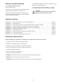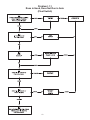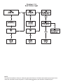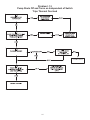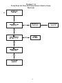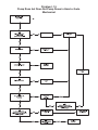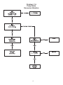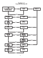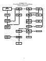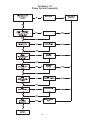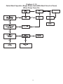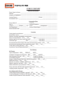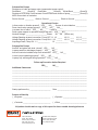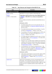
1
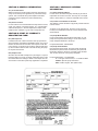
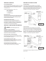
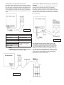
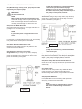
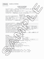
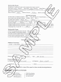
PUMP STATION START-UP
and TROUBLESHOOTING MANUAL
SH Series
SE Series
OGP
Crown PO6
IMPORTANT!
A Crane Co. Company
Read all instructions in this manual before operating pump.
As a result of Crane Pumps & Systems, Inc., constant product improvement program,
product changes may occur. As such Crane Pumps & Systems reserves the right to
change product without prior written notification.
420 Third Street
Piqua, Ohio 45356
Phone: (937) 778-8947
Fax: (937) 773-7157
www.cranepumps.com
83 West Drive, Brampton
Ontario, Canada L6T 2J6
Phone: (905) 457-6223
Fax: (905) 457-2650
Form No. 101686-Rev. B
TABLE OF CONTENTS
SAFETY FIRST ............................................................................................... 3
A.
GENERAL INFORMATION ..............................................................................4
B.
START-UP / WARRANTY REGISTRATION FORM .........................................4
C.
NECESSARY GENERAL INFORMATION .......................................................4
D.
CONTROLS ...................................................................................................5
E.
JUNCTION BOX INFORMATION ....................................................................5
F.
ELECTRICAL CHECK .....................................................................................5 - 6
G.
PERFORMANCE CHECK................................................................................7
H.
FINAL CHECK .................................................................................................8
I.
TROUBLE SHOOTING ....................................................................................11 - 28
PROBLEM FLOW CHARTS ............................................................................12 - 21
WARRANTY ...................................................................................................29
WARRANTY REGISTRATION .........................................................................30
RETURNED GOODS POLICY.........................................................................30
START-UP REPORT ........................................................................................31 - 32
SPECIAL TOOLS AND EQUIPMENT
INSULATION TESTER (MEGGER)
DIELECTRIC TESTER
SEAL TOOL KIT ( see parts list)
PRESSURE GAUGE KIT (see parts list)
Other brand and product names are trademarks or registered trademarks of their respective holders.
® Barnes is a registered trademark of Crane Pumps & Systems, Inc
1994, 2002, 2003, 1/2004, 8/2004, 4/05 , 3/06, 8/06, 1/07, 2/07
2
Alteration Rights Reserved
SAFETY FIRST!
PLEASE READ THIS BEFORE INSTALLING
OR OPERATING PUMP.
GENERAL
1.
2.
3.
4.
5.
6.
7.
8.
9.
10.
11.
12.
13.
14.
15.
16.
Most accidents can be avoided by using COMMON SENSE.
Read this operation and maintenance instruction manual.
Do not wear loose clothing that may become entangled in the impeller or other moving parts.
Always wear appropriate safety gear, such as safety glasses, when working on the pump or piping.
Bronze/brass and bronze/brass fitted pumps may contain lead levels higher than considered safe for potable water systems. Various government agencies have determined that leaded copper alloys should not be used in potable water applications. For nonleaded copper alloy materials of construction, please contact factory.
Minimize the amount of cooking grease entering the system.
Do Not leave pump cover off the basin, except while servicing, to prevent entrance of foreign materials such as rocks, metal, soil,
animals or humans.
Prevent large articles of clothing, large amounts of chemicals, other materials or substances such as are uncommon in domestic
sewage from entering the system.
During power black-outs, discontinue water consumption at the home(s) to prevent sewage from backing up into the house.
Prevent infiltration or direct flow of rain or run-off water into the pump basin to minimize pump cycling. This will prevent overloading
the treatment facility, and will facilitate swift transportation of sewage.
Always keep the shut-off valve completely open when system is in operation (unless advised otherwise by the proper authorities).
Keep the control panel locked or confined to prevent unauthorized access to it.
If the pump is idle for long periods of time, it is advisable to start the pump occasionally by adding water to the basin.
Before removing the pump from the basin, be sure to close the shut-off valve. (This prevents back flow from the pressure sewer.)
Make sure level controls are provided at time of installation.
This basin system is intended for use with water, sewage and effluent applications. This basin must be vented in accordance with
local codes. This basin system is not to be installed in locations in which the basin interior would be classified as a hazardous location in accordance with NEC ANSI/NPFA 70.
PUMPS
17.
18.
19.
20.
21.
22.
23.
24.
25.
26.
27.
28.
Recommended no more than 10 starts per hour.
Pumps build up heat and pressure during operation-allow time for pumps to cool before handling or servicing.
Only qualified personnel should install, operate and repair pump.
Keep clear of suction and discharge openings. DO NOT insert fingers in pump with power connected.
Do not pump hazardous materials (flammable, caustic, etc.) unless the pump is specifically designed and designated to handle them.
Do not block or restrict discharge hose, as discharge hose may whip under pressure.
Make sure lifting handles are securely fastened each time before lifting.
Do not lift pump by the power cord.
Do not exceed manufacturers recommendation for maximum performance, as this could cause the motor to overheat.
Secure the pump in its operating position so it can not tip over, fall or slide.
Keep hands and feet away from impeller when power is connected.
Submersible Pumps are not approved for use in swimming pools, recreational water installations, decorative fountains or any installation where human contact with the pumped fluid is common.
29. Do not operate pump without safety devices in place.
30. Always replace safety devices that have been removed during service or repair.
ELECTRICAL
31. To reduce risk of electrical shock, pump must be properly grounded in accordance with the National Electric Code (NEC) and all applicable state and local codes and ordinances.
32. To reduce risk of electrical shock, always disconnect the pump from the power source before handling or servicing. Lock out power
and tag.
33. Any wiring of pumps should be performed by a qualified electrician.
34. Never operate a pump with a power cord that has frayed or brittle insulation.
35. Cable should be protected at all times to avoid punctures, cut, bruises and abrasions - inspect frequently.
36. Never handle connected power cords with wet hands.
37. Do not remove cord and strain relief. Do not connect conduit to pump.
38. To reduce risk of electrical shock, all wiring and junction connections should be made per the NEC and applicable state and local
codes. Requirements may vary depending on usage and location. See wiring diagrams in manual.
39. Do Not operate the pump in the “HAND” control position and leave the pump unattended.
40. CAUTION - This unit may have more than one connection to the source of supply. To reduce the risk of electric shock, disconnect all
such connections before servicing.
41. All connections inside this tank and/or junction box must be made with listed watertight connectors.
IMPORTANT! BARNES® PUMPS, INC. IS NOT RESPONSIBLE FOR LOSSES, INJURY, OR DEATH RESULTING FROM A
FAILURE TO OBSERVE THESE SAFETY PRECAUTIONS, MISUSE OR ABUSE OF PUMPS OR EQUIPMENT.
3
SECTION C: NECESSARY GENERAL
INFORMATION
SECTION A: GENERAL INFORMATION
A-1) To the Purchaser:
Within the manual you will find the necessary information to
verify correct start-up and registration of your Barnes Pump
system. This manual will also provide helpful information
concerning proper maintenance and troubleshooting
procedures.
A-2) Service Centers:
For the location of the nearest Barnes Pumps Service Center,
check your catalog, your Barnes Pumps, Inc., representative
or Barnes Pumps, Inc., Service Department in Piqua, Ohio,
telephone 937-778-8947 or go to www.cranepumps.com.
SECTION B: START UP / WARRANTY
REGISTRATION FORM
B-1) Start Up Form:
Included at the end of this manual is a start-up report sheet
which should be completed as applicable. Return one copy to
Barnes and store the second in the control panel or with the
pump manual. It is important to record this data at initial startup since it will be useful to refer to should servicing the pump
be required in the future.
B-2) Sample Form:
We have also included a sample form (see Pages 11-12) that
has been filled out, to help you better understand some of the
information Barnes is asking for. Refer to the sample form as
each section of the start up warranty registration is explained.
4
C-1) Owner Name & Address:
In most cases, this will be the party that will pay for and be
responsible for service of the unit. This may be a municipal
water or sewer district, or it may be individual home owners.
C-2) Location of Installation & Contact:
The address of where the basin is physically located and who
is main contact.
As shown on the sample form, the owner if City of Piqua,
but they have installed the basin at a house located at 234
Second Street.
C-3) Pump Model Number:
Pump model number will give Barnes information on your
pump size and performance rating, it can be found on the
pump nameplate attached to the pump.
Pump Model Number: 4SHVA30042
C-4) Pump Serial Number:
Like the basin serial number, the pump serial number will
tell Barnes the plant location of where the pump was built,
information specific to the pump, and date pump was built.
This can also be found on the pump nameplate.
Pump Serial Number = C575824-0897
C = Covington Avenue Plant, T = Third Street Plant
575824 = Specific pump information
0897 = Built in August, 1997 (Date Code)
SECTION D: CONTROLS
SECTION F: ELECTRICAL CHECK
D-1) Panel Model Number:
The panel model number will tell Barnes whether your control
panel is a Simplex or Duplex and what options you may have.
The panel model number can be usually found inside the
control panel cover.
F-1) Single Phase:
Check and record incoming voltage to the control panel
circuit breaker with the pump off, the reading is taken across
L1 and L2 of the circuit breaker on the incoming side (see
Figure 1).The voltage reading should be within ±10% of pump
rated volts (pump rated volts can be found on the pump
nameplate). If your pump is three phase, mark N/A.
Control Panel Model Number = UGP -101-21
UGP = Pump Series
101 = Panel Options
2 = Horsepower
1 = Voltage & Phase
D-2) Is Interior Dry:
Check YES or NO. The interior of the control panel must be
clean and dry at startup. If moisture is present, determine
cause and correct. Check to make sure that all conduit
entries in the panel are sealed!
D-3) Are All Connections Tight:
Check YES or NO. It is recommended that all wire
connections be checked for tightness in addition to the
pump power, control wires, level sensor, and service wires.
Check factory connections in the panel to assure that no
connections were loosened during shipping.
Figure 1
SECTION E: JUNCTION BOX INFORMATION
CAUTION!
Check to be certain that all power is off.
E-1) Debris in Piping or Wet Well:
Indicate by checking YES or NO.Inspect the basin for
anything that may have been inadvertently left in the bottom
or rocks and excessive amounts of dirt that may have been
dropped in the basin during installation.
F-2) Three Phase:
Check and record incoming voltage to the control panel
circuit breaker with the pump off. Readings should be taken
across L1 - L2, L2 - L3, and L3 - L1 on the incoming side of
the circuit breaker, (see Figure 2). The voltage reading should
be within ± 10% of pump rated volts and should be balanced
within ± 1%. Pump rated volts can be found on the pump
nameplate. If your pump is single phase, mark N/A.
E-2) Is Junction Box / Control Panel Dry:
Check YES or NO. The junction box must be dry to avoid
power/control problems. If any moisture is present, wipe dry
or use a blow dryer if necessary.
E-3) Are all Wire Connections Tight:
Check YES or NO. All wire nut connections in the junction
box should be tight. In addition, look for wires that may be
exposed beyond the end of the wire nut.
E-4) Are Pump Cords away from Pump:
Check YES or NO. Do not allow excess pump or control
cords to hang any lower than the top of the pump.
Figure 2
If incorrect power supply readings are recorded, contact local
power source.
5
F-3) Resistance of Pump Power Connections:
Record the ohms (resistance) reading of the motor windings
at the pump power connections on the control panel terminal
strip with power off. Readings should be taken between red/
black, black/white, red/white, (see Figure 3).Compare your
ohms readings to the electrical chart in the pump operations
manual, you should be within ±5% of resistance listed on the
chart.
F-4) Resistance Between Ground Lug and outside Pump
Case/Rail:
Record the ohms (resistance) reading between the control
panel ground lug and the pump case or the stainless
steel rail, if your basin has the rail system (see Figure 4).
Resistance readings of less than 1 ohm indicate a good safe
ground. (If basin is not located next to the panel, a temporary
extension wire from the basin to the meter may be required to
take this reading.)
Figure 3
1 Phase
Red - Black
Start + Run Resistance
Red - White
Start Resistance
Black - White
Run Resistance
Figure 5
3 Phase
Red - Black
All Three Resistance
readings should be the
same.
Red - White
Black - White
NOTE:
If OHMS reading are not within range, disconnect
wires at terminal strip and check again.
Figure 4
6
F-5) Insulation Check at Control Panel: (MEG-OHM)
The insulation check of the pump power leads is taken at
the control panel terminal strip between red/ground, black/
ground, and white/ground with the power off, record your
readings in meg-ohms (see Figure 5). Readings of 5 megohm and higher are acceptable. Note “0” readings indicate
a dead short.Correct the problem before proceeding. THIS
TEST MUST BE PERFORMED AFTER THE GROUND
RESISTANCE CHECK IN SECTION F-4.
SECTION G: PERFORMANCE CHECK
NOTE:
If pump does not come on, push the start button
in the control panel. Record the amperage
readings of L1 and L2, they should not exceed
more than 10% over the pump nameplate amps. If
your pump is a three phase, mark N/A.
G-1) With discharge valve(s) closed, pull pump and rotate
impeller by hand, replace pump.
IMPORTANT!
All power must be off
NOTE:
With the pump power off (circuit breaker) fill the
wetwell with enough water to trip the high water alarm
float. Open discharge valve in the wetwell and, if
necessary, the discharge valve at the force main.
G-5) Amperage Load at Line Connection:
Three Phase: Using a clamp on amp meter, clamp the amp
meter to the L1 wire between the service drop and control
panel circuit breaker, (see Figure 7).
G-2) Is the High Water Alarm On:
Check YES or NO.Turn power on, is the high water alarm on
(red light on top of control panel).
NOTE:
If your control panel is equipped with an alarm
horn, push the button on the panel cover to
silence.
Let the pump run until the alarm light turns “off”, and manually
turn power off at the control panel circuit breaker.
G-3) Alarm Shut Off at Appropriate Level:
Check YES or NO.
Measure the water depth (with pump off) when the alarm
shuts off and record if desired.
G-4) Amperage Load at Line Connection:
Single Phase: Using a clamp on amp meter, clamp amp
meter to the L1 wire between the service drop and control
panel circuit breaker. Turn pump power on at the control
panel circuit breaker, (see Figure 6).
Figure 7
NOTE:
If pump does not come on, push the start button
in the control panel.
Record the amperage readings on L1, L2, and L3,
they should not exceed 10% over the pump nameplate
amps. If your pump is a single phase, mark N/A.
G-6) Did the Pump Shut Off at the Normal Off Point:
Check YES or NO. The pump should have pumped the water
level down to the predetermined “Off” point and shut off
automatically.
G-7) Visible Leaks:
Check YES or NO. Did you notice any visible leaks when
pump was running. You should look for leaks around
discharge fitting within the basin, and possible ground water
entering the basin around the inlet pipe or cord entries.
G-8) Equipment Difficulties:
List any difficulties encountered during start up and note
what, if any, corrective action was taken.
NOTE:
If you encounter any problems during start up,
refer to the trouble shooting section of this
manual.
Figure 6
7
SECTION H: FINAL CHECK
H-1) Has the End User Received All Manuals:
After completion of a successful start up, the end user
(homeowner) should receive the Installation Manual, Control
Panel Installation/Operation Manual, Pump Installation/
Operation Manual, User Guide, if applicable, and this Start
Up Manual.
H-2) Has the End User been Briefed on Warranty:
A copy of the warranty is in the back of all manuals and
should be pointed out to the end user.
H-3) Are the Operation / Maintenance Manuals Saved:
Advise end user to save all Installation/Operation Manuals
and keep for future reference.
8
H-4) Received Above Information:
If possible, have those present at start up, sign and date the
start up form if the system is operating properly.
NOTE:
If duplex system is being started, fill out duplicate
forms, mark first set PUMP #1 or LEAD, mark
second set PUMP #2 or LAG.
M
A
S
9
LE
P
M
A
S
10
LE
P
SECTION I: TROUBLE SHOOTING
I-1) Trouble Shooting Flow Charts:
How to read flow charts
3. The Reference Number can be found in Section I.2, (see
pages 26 - 32) Corrective Action.
4. Corrective Action instructions, Section I.2.1 through
I.2.34 will give details on trouble shooting your problem
1. Based on your observations and initial inspection of the
system, select a Flow Chart I.1.1 through I.1.10.
CAUTION!
Shut off power unless otherwise noted before
making electrical/mechanical checks.
2. All flow charts start at the top left hand corner, follow
the chart in the direction of the arrows. Note the reference
number at the top of each block.
TROUBLE SHOOTING
PROBLEM I.1.1 - Runs in Hand, Does not run in Auto (Float Switch) ....................................................................... Page 12
PROBLEM I.1.2 - Seal Failure Light ........................................................................................................................... Page 13
PROBLEM I.1.3 - Pump shuts off and turns on independent of switch, trips thermal overload ................................. Page 14
PROBLEM I.1.4 - Pump runs but does not pump down in Hand or Auto. Electrical .................................................. Page 15
PROBLEM I.1.5 - Pump runs but does not pump down in Hand or Auto. Mechanical ............................................... Page 16
PROBLEM I.1.6 - Pump noise, Excessive vibration ................................................................................................... Page 17
PROBLEM I.1.7 - Pump will not shut off..................................................................................................................... Page 18
PROBLEM I.1.8 - Circuit breaker trips or fuse blows, pumps do not start.................................................................. Page 19
PROBLEM I.1.9 - Pump cycles frequently.................................................................................................................. Page 20
PROBLEM i.1.10 - Failed start capacitor when pump turns on .................................................................................. Page 21
ELECTRICAL SAFETY POINTS
Before attempting any repair be sure incoming power is OFF, double check with a volt meter.
1. Visually check power cable for signs of deterioration.
2. Visually check for water intrusion in control panel.
3. Check for low resistance between control panel and ground.
4. Make sure ground (green) in control panel is properly secure.
5. Pull fuses and keep in safe place.
6. Tag control panel with “CAUTION” tag.
7. Secure control panel with padlock.
8. ALWAYS disconnect the pump from the power source before handling or servicing.
9. NEVER handle connected power cords with wet hands.
10. NEVER operate a pump with power cord that is split, frayed, or has brittle insulation.
11
Problem I.1.1
Runs in Hand, Does Not Run in Auto
(Float Switch)
12
Problem I.1.2
Seal Failure Light
NOTE:
The Seal Probe (Moisture Sensor) is a Normally Open (N/O) Detector. SH Series and explosion proof pumps have a
330K Ohm test resistor across the probes. If a 330K reading is obtained, this should be considered “Open”
13
Problem I.1.3
Pump Shuts Off and Turns on Independent of Switch
Trips Thermal Overload
14
Problem I.1.4
Pump Runs but Does Not Pump Down in Hand or Auto.
Electrical
15
Problem I.1.5
Pump Runs but Does Not Pump Down in Hand or Auto.
Mechanical
16
Problem I.1.6
Pump Noise
Excessive Vibration
17
Problem I.1.7
Pump Will Not Shut Off
18
Problem I.1.8
Circuit Breaker Trips or Fuse Blows,
Pumps Do Not Start
19
Problem I.1.9
Pump Cycles Frequently
20
Problem I.1.10
Failed Start Capacitor (SIngle Phase Units With Start Circuit in Panel)
When Pump Turns On
21
SECTION I: TROUBLE SHOOTING
I-2.1) Check for Correct Wiring:
Check all switch control leads for correct color coding or
number marking. Trace all leads through junction box to
correct terminal in the control panel. Refer to appropriate
wiring diagrams in service manual, control panel, and junction
box.
NOTE:
Pump power leads at control panel terminal strip
must be red to R, black to B, and white to W.
When checking for correct wiring, look for moisture in the
control panel or junction box, corrosion at wire connections,
loose wire connections, and poorly stripped wires. All of the
above can contribute to control problems.
Turn on the Main Circuit Breaker and manually pump the
basin down to the bottom of the pump volute. Turn off the
Main Breaker and repeat the continuity check. Off, On, alarm
switch should be open (no continuity). If these conditions are
not met, go to L.2.5.
I-2.5) Continuity Check of Controls:
AT JUNCTION BOX. Fill wetwell to a level above the
discharge elbow, this will allow all switches to be closed.
Refer to the wiring diagram supplied with the basin, turn off
the main breaker, disconnect all switch control leads at the
junction box, check for continuity from switch controls to
junction box. Off, On, and alarm switches should be closed
(continuity), (see Figure 9).
I-2.2) Check Water Level:
Remove wetwell cover and check water level. If the water
level is above the “On” float, this should be sufficient to close
all switches.
I-2.3) Float Hang Up:
Visually check float movement while filling basin. If floats get
hung up on pump or rail system, reposition floats and check
again. Inspect floats for build-up of solids, clean, and check
operation.
I-2.4) Continuity Check of Controls:
Turn off Main Circuit Breaker at control panel. Fill basin to a
level above the discharge elbow, this will allow all switches
to be closed. Referring to the wiring diagram supplied with
panel, check for continuity at the control panel terminal strip.
Off, On, and alarm switches should be closed (continuity),
(see Figure 8).
Figure 9
Turn on breaker and manually pump the basin down to the
bottom of the pump volute, Off, On alarm switch should be
open (lack of continuity). If these conditions are not met,
replace switch.
CAUTION!
When the breaker is turned on, the control leads
may be energized with 120 V. Make sure they are
safely tied off and isolated.
I-2.6) Replace Cable between Panel & Junction Box:
If it is necessary to replace the direct burial cable, note the
following:
1. Is the cable the same size/type.
2. Reseal conduit entering control panel.
3. Are the cord grip grommets in the junction box the
correct size.
4. Use “NEW” wire nuts in the junction box.
5. How did the cable get damaged?
Figure 8
22
I-2.7) Moisture in Control Panel/Junction Box:
The accumulation of moisture in the controls can lead to a
number of electrical problems. If moisture is evident, turn
power to the control panel off and thoroughly dry with a blow
dryer. After drying, check for loose or corroded connections,
determine cause of moisture, and correct.
I-2.9) Continuity Check Moisture Sensor, Junction Box:
NOTE:
The moisture sensor is a (N/O) normally open
detector. SH Series and explosion proof pumps
have a 330K Ohm test resistor across the probes.
If a 330K reading is obtained, this should be
considered “Open”.
I-2.8) Continuity Check Moisture Sensor, Control Panel:
NOTE:
The moisture sensor is a (N/O) normally open
detector. SH Series and explosion proof pumps
have a 330K Ohm test resistor across the probes.
If a 330K reading is obtained, this should be
considered “Open”.
Figure 11
Figure 10
In the event of a moisture detect, check the moisture sensor
leads for continuity. Refer to wiring diagram supplied with
panel. If resistance is detected, check for continuity in
junction box, (see Figure 10).
If checking moisture sensor leads at the control panel for
continuity indicates the presence of moisture, disconnect
the moisture sensor leads in the junction box and check for
continuity from junction box to pump, (see Figure 11).
I-2.10) Excessive Water Temperature:
Continuous water temperatures above 100°F (38°C) may
cause the pump temperature sensor to open and trip the
thermal overload. To determine if this is happening, turn
power off and fill the basin with cold water (allowing time for
the pump to dissipate heat). Turn power on and check for
normal pump cycle. Continuous operation with the pump
unsubmerged may result in the same symptoms. Consult
pump manual for minimum submergence requirements.
NOTE:
Water temperature not to exceed 160°F (71°C)
intermittent.
23
I-2.11) Check Motor Amperage:
With the power off, clamp the amp robe around the
appropriate lead. Fill basin so pump will be under load and
turn pump on. Record amperage readings on all necessary
leads. Compare your recorded amperage with the nameplate
rating and the amperage recorded on the system start-up
sheets. (See Figures 12 and 13). Amps will drop as motor
becomes warm.
NOTE:
Must not exceed ± 10% nameplate amps at
nominal voltage.
I-2.13) Check Application:
Check for undersized pump or incorrect impeller installed
for conditions. Recheck performance curve. It is possible
the original pump selection is at fault or system head has
changed.
I-2.14) Correct Pump Rotation:
All Barnes Submersible Grinder Pumps rotate “clockwise”
looking down at the pump. To check rotation, suspend the
pump freely, momentarily apply power, and observe the
“kickback”. Kickback should always be in a counterclockwise
direction as viewed from the top of the pump motor housing.
Incorrect rotation three phase: In the event that the rotation
is incorrect for a three phase pump, interchange any two
power cable leads at the control panel. Do not change power
cable leads in the pump. Recheck the “kickback” rotation
again by momentarily applying power.
Incorrect rotation single phase: In the unlikely event that
the rotation is incorrect for a single phase pump, contact a
Barnes Pump’s Service Center.
I-2.15) Check for correct incoming voltage:
Single Phase: Check incoming voltage on the line side of the
control panel circuit breaker. Readings of ± 10% of published
voltage (nameplate) are acceptable. A true check of the
voltage supply to the motor must be taken with the pump
operating under load, (see Figure 14).
Take voltage readings with the pump “off” and readings with
the pump “on”, compare the two readings and note any
difference.
Figure 12
Figure 13
I-2.12) Jammed Cutter/Impeller:
With the power off and the control panel locked, check the
cutter/impeller for freedom of movement, you should be able
to move the cutter by hand.
If clogged, clear the cutter/impeller cavity of any obstruction.
If all the debris cannot be removed, it may be necessary to
remove the volute to clean around the impeller, refer to pump
Installation/Operation Manual.
24
Figure 14
If incorrect power supply readings are recorded, contact local
power source.
Three Phase: Check incoming voltage on the pump side of
the control panel circuit breaker. Readings of ± 10% of the
published voltage (nameplate) are acceptable. A true check of
the voltage supply to the motor must be taken with the pump
operating under load, (see Figure 15).
Take voltage readings between all three legs with the pump“
off” and readings with the pump “on”, compare the two
readings and note any difference. Also note whether or not
the voltages between all three legs are similar (balanced).
I-2.18) Excessive Inflow:
Inflow may be at a rate greater than pumping rate, compare
inflow with pump curve.
Excessive inflow may also be due to ground water infiltration.
With wetwell level pumped down as low as possible, check
for ground water leaks around inlet and discharge lines.
Check for leaks through damaged or cracked basin wall. Note
the wetwell installation, if the top of the basin is below grade
level, ground water may be entering around the lid or vent.
I-2.19) Discharge Leak:
Pump wetwell down (below discharge plumbing) observing
discharge line, check for plumbing leaks while line is under
pressure, repair fixtures, or discharge gasket as required.
I-2.20) Impeller/Cutter Damage:
If the impeller and or cutter is damaged or excessively worn,
it must be replaced, see appropriate disassembly/assembly
section in this Pump manual. NOTE: If the cutter on grinder
pumps is excessively worn the shredding ring may be
reversed.
I-2.21) Discharge Head Too High:
Check total head and pump performance curve and that the
correct impeller has been installed or consult factory.
Figure 15
If incorrect power supply readings are recorded, contact local
power source.
I-2.16) Discharge Valve Open:
Inspect discharge and check valves for correct installation.
Are they installed backwards. (check valve). Is the valve
at the basin and main open. Is the check valve stuck. Is
discharge line from pump to main plugged.
I-2.17) Pump Air Locked:
If the pump has become air locked, it will not pump the basin
down, air locked pumps may be corrected in one of the
following manners.
• Shake pump up and down by the lifting rope, do not pull
on the power or control cables.
• Close and open discharge valve a few times in quick
succession.
• Start and stop pump a few times allowing 2 or 3 minutes
between stop and restart.
I-2.22) Discharge Plumbing or Rail Assembly Loose:
With pump running, check for loose pipe attachments and/or
loose rail assembly. Make any necessary adjustments.
I-2.23) Adjust Float or Replace Switch:
If floats are used, you may have to reposition “on” float to get
a longer pump down cycle. You may also have a float stuck in
the open position.
I-2.24) Connector Sticking:
The connector used in many control panels can be tripped
on/off manually. With the liquid level above the “on” float, turn
pump on, this will close the connector. Allow the system to
pump down to the “off” level. If the pump does not shut off,
manually turn it off. If the connector is still closed, it is sticking
and should be replaced.
25
I-2.25) Check Circuit Breaker and Fuse Rating:
NOTE:
Control Panel Circuit Breaker (short circuit
protection) should be rated at least 20% higher
than pump full load amps, but no more than
3 times the full load amps. Current overloads
should be sized in accordance with pump
nameplate amps.
Conditions of Motor and Leads
A new motor (without Drop Cable).
A used motor which can be reinstalled in the well.
Motor in well. Ohm readings are for drop cable plus motor.
A new motor in well.
A motor in the well in reasonably good condition.
A motor which may have been damaged by lighting or with damaged leads.
DO NOT pull the pump for this reason.
A motor which definitely has been damaged or with damaged cable. The pump
should be pulled and repairs made to the cable or the motor replaced. The motor will not fail for this reason alone, but it will probably not operate for long.
A motor which has failed or with completely destroyed cable insulation. The
pump must be pulled and the cable repaired or the motor replaced.
26
OHM Value
20,000,000 (or More)
10,000,000 (or More)
MEG-OHM Value
20.0
10.0
2,000,000 (or More)
500,000 - 2,000,000
20,000 - 500,000
5.0
0.5 - 5.0
0.02 - 0.5
10,000 - 20,000
0.01 - 0.02
Less Than 10,000
0 - 0.01
I-2.26) Megger Control Panel to Pump:
With power “off” at the control panel, disconnect the pump
power cable leads from the control panel.
I-2.29) Defective Check Valve:
If the check valve is not installed properly or is defective, this
will allow back flow at the end of the pump cycle. Remove
and examine check valve for proper installation and freedom
of movement, repair, or replace.
I-2.30) Faulty Relay or Start Capacitor:
Checking the start relay, (see Figure 18).
CAUTION!
Be sure to short out start capacitor and remove
wires from relay terminals before making any
resistance checks with ohmmeter. Always remove
all power from circuits before making resistance
measurements.
Figure 16
Connect one lead to ground (green) and check red, black,
white power cord leads, (see Figure 16). A minimum
insulation resistance readings of 5MΩ is considered
acceptable. Readings of less than 5MΩ indicates a bad circuit
between control panel and pump, (See Resistance Values on
Page 30).
I-2.27) Megger Junction Box to Pump:
With power “off” at the control panel, disconnect the pump
power cable leads at the junction box.
Figure 18
Measure Between Terminals 1 and 2: Zero Ohms.
Measure Between Terminals 2 and 5: Actual coil resistance.
Relay Check: The terminals on the relay used in this check
are numbered. The numbers are stamped on the backlight
housing next to the terminals. With Ohmmeter set on the R x1
scale, the reading between Terminals number 1 and number
2 should be all the way to the right of the scale or zero. On
some occasions due to higher than expected amp draws
through the relay, the contact may permanently “weld”
together. A relay with welded contacts will cause start
capacitors to overheat and become defective. A relay with
welded contacts will often measure good with an ohmmeter
(O) even though it is defective.
Figure 17
Connect one lead to ground (green) and check red, black,
white power cord leads, (see Figure 17). A minimum
insulation resistance reading of 5MΩ is considered
acceptable. Readings of less than 5MΩ indicate a bad
circuit between the junction box and pump, pull the pump for
service.
I-2.28) Poor Neutral:
With power “off” check for “clean” tight neutral connection on
control panel terminal strip, also check neutral connection at
power supply. Refer to appropriate wiring diagram in service
manual.
27
If start capacitor is found faulty, it is suggested that the
relay cover be removed (two screws) and the contact
points physically checked for contact surface condition
as well as freedom of movement.
The reading between Terminal number 2 and number 5
should show the resistance in the relay holding coil. If it
shows open, then the coil has burned up. If it shows no
resistance, it may have shorted out. Either way, replace the
relay.
I-2.31) Checking Run and Start Capacitors:
CAUTION!
IF CAPACITORS ARE BEING CHECKED WHILE
STILL IN THE CONTROL, PROCEED WITH STEPS
1 - 4.
1. Remove and lock “off” all power to control.
2. Using a screwdriver, with an insulated handle,
short circuit each capacitor by placing the blade of the
screwdriver across the two terminals of each capacitor.
This will “discharge” the capacitor.
3. Remove all leads connected to capacitor terminals. (It is
most important to make note of the position of leads so that
they will be properly reconnected after testing.)
4. Remove any resistors found across the capacitor
terminals (usually found on start capacitors).
CHECKING CAPACITORS: The following checks made with
a Simpson Ohmmeter, Model Number 372, or equivalent,
apply to both RUN and START CAPACITORS except for the
range setting or scale used. (If a digital meter with a capable
of measuring capacitance is used, verify the reading obtained
matches the capacitance on the capacitor case)
Use scale R x 100K for Run Capacitors and R x 10K for Start
Capacitors.
The following check can be taken with capacitors on the
bench or in the control.
28
Check each capacitor by clipping an ohmmeter lead to one
of the capacitor terminals and touching the other ohmmeter
lead to the other terminal for a few seconds. NOTE: Results
as follows:
• A good Run Capacitor is indicated by pointer of
ohmmeter moving towards zero (the figure “0” on righthand side of scale) and then slowly drifting back towards
the left.
• When checking a Start Capacitor, you will note
(depending on MFD rating), that some of them will not
move the ohmmeter needle to complete zero before it is
on its way back and that, unlike the Run Capacitors, the
needle will not always move all the way to the left side of
the scale. The reason for this is the much higher rating of
Start Capacitors.
• If the pointer remains at infinity (00), capacitor is “open”.
• If the pointer remains at zero (0), capacitor is “shorted” A
shorted or open capacitor must be replaced.
NOTE:
The above test builds up a small charge in the
capacitor which it will store. Before repeating test
or reconnecting capacitors, discharge capacitor
by shortening terminals with an insulated
screwdriver. A good capacitor will discharge a
small spark.
Check each metal Run Capacitor for grounds by clipping one
ohmmeter lead to capacitor case and the other ohmmeter
lead, in turn, to each of the two capacitor terminals. With
ohmmeter set at R x 100K, pointer should remains at
infinity(00) on extreme left of scale. Start Capacitors often
have backlight case and cannot be checked by this method
for ground.
Limited 24 Month Warranty
Crane Pumps & Systems warrants that products of our manufacture will be free of defects in material and workmanship
under normal use and service for twenty-four (24) months after manufacture date, when installed and maintained
in accordance with our instructions.This warranty gives you specific legal rights, and there may also be other rights
which vary from state to state. In the event the product is covered by the Federal Consumer Product Warranties Law
(1) the duration of any implied warranties associated with the product by virtue of said law is limited to the same
duration as stated herein, (2) this warranty is a LIMITED WARRANTY, and (3) no claims of any nature whatsoever
shall be made against us, until the ultimate consumer, his successor, or assigns, notifies us in writing of the defect,
and delivers the product and/or defective part(s) freight prepaid to our factory or nearest authorized service station.
Some states do not allow limitations on how long an implied warranty lasts, so the above limitation may not apply.
THE SOLE AND EXCLUSIVE REMEDY FOR BREACH OF ANY AND ALL WARRANTIES WITH RESPECT TO ANY
PRODUCT SHALL BE TO REPLACE OR REPAIR AT OUR ELECTION, F.O.B. POINT OF MANUFACTURE OR
AUTHORIZED REPAIR STATION, SUCH PRODUCTS AND/OR PARTS AS PROVEN DEFECTIVE. THERE SHALL BE
NO FURTHER LIABILITY, WHETHER BASED ON WARRANTY, NEGLIGENCE OR OTHERWISE. Unless expressly
stated otherwise, guarantees in the nature of performance specifications furnished in addition to the foregoing material
and workmanship warranties on a product manufactured by us, if any, are subject to laboratory tests corrected for
field performance. Any additional guarantees, in the nature of performance specifications must be in writing and such
writing must be signed by our authorized representative. Due to inaccuracies in field testing if a conflict arises between
the results of field testing conducted by or for user, and laboratory tests corrected for field performance, the latter
shall control. RECOMMENDATIONS FOR SPECIAL APPLICATIONS OR THOSE RESULTING FROM SYSTEMS
ANALYSES AND EVALUATIONS WE CONDUCT WILL BE BASED ON OUR BEST AVAILABLE EXPERIENCE AND
PUBLISHED INDUSTRY INFORMATION. SUCH RECOMMENDATIONS DO NOT CONSTITUTE A WARRANTY OF
SATISFACTORY PERFORMANCE AND NO SUCH WARRANTY IS GIVEN.
This warranty shall not apply when damage is caused by (a) improper installation, (b) improper voltage (c) lightning
(d) excessive sand or other abrasive material (e) scale or corrosion build-up due to excessive chemical content. Any
modification of the original equipment will also void the warranty. We will not be responsible for loss, damage or labor
cost due to interruption of service caused by defective parts. Neither will we accept charges incurred by others without
our prior written approval.
This warranty is void if our inspection reveals the product was used in a manner inconsistent with normal industry practice
and\or our specific recommendations. The purchaser is responsible for communication of all necessary information
regarding the application and use of the product. UNDER NO CIRCUMSTANCES WILL WE BE RESPONSIBLE FOR
ANY OTHER DIRECT OR CONSEQUENTIAL DAMAGES, INCLUDING BUT NOT LIMITED TO TRAVEL EXPENSES,
RENTED EQUIPMENT, OUTSIDE CONTRACTOR FEES, UNAUTHORIZED REPAIR SHOP EXPENSES, LOST
PROFITS, LOST INCOME, LABOR CHARGES, DELAYS IN PRODUCTION, IDLE PRODUCTION, WHICH DAMAGES
ARE CAUSED BY ANY DEFECTS IN MATERIAL AND\OR WORKMANSHIP AND\OR DAMAGE OR DELAYS IN
SHIPMENT. THIS WARRANTY IS EXPRESSLY IN LIEU OF ANY OTHER EXPRESS OR IMPLIED WARRANTY,
INCLUDING ANY WARRANTY OF MERCHANTABILITY OR FITNESS FOR A PARTICULAR PURPOSE.
No rights extended under this warranty shall be assigned to any other person, whether by operation of law or otherwise,
without our prior written approval.
A Crane Co. Company
420 Third Street
Piqua, Ohio 45356
Phone: (937) 778-8947
Fax: (937) 773-7157
www.cranepumps.com
83 West Drive, Brampton
Ontario, Canada L6T 2J6
Phone: (905) 457-6223
Fax: (905) 457-2650
IMPORTANT!
WARRANTY REGISTRATION
Your product is covered by the enclosed Warranty.
To complete the Warranty Registration Form go to:
http://www.cranepumps.com/ProductRegistration/
If you have a claim under the provision of the warranty, contact your local
Crane Pumps & Systems, Inc. Distributor.
RETURNED GOODS
RETURN OF MERCHANDISE REQUIRES A “RETURNED GOODS AUTHORIZATION”.
CONTACT YOUR LOCAL CRANE PUMPS & SYSTEMS, INC. DISTRIBUTOR.
Products Returned Must Be Cleaned, Sanitized,
Or Decontaminated As Necessary Prior To Shipment,
To Insure That Employees Will Not Be Exposed To Health
Hazards In Handling Said Material. All Applicable Laws
And Regulations Shall Apply.
A Crane Co. Company
START-UP REPORT
General Information
Pump Owner’s Name: __________________________________________________________
Address: ____________________________________________________________________
Location of Installation: _________________________________________________________
Contact Person: __________________________________Phone: _______________________
Purchased From: _____________________________________________________________
Nameplate Data
Pump Model #: ___________________ Serial #:_____________________________________
Part #: __________________________ Impeller Diameter: ____________________________
Voltage: _________ Phase: _____ Ø
Hertz: ____________Horsepower: _______________
Full Load Amps: ___________________ Service Factor Amps: __________________________
Motor Manufacturer: ___________________________________________________________
Controls
Control panel manufacturer: _____________________________________________________
Model/Part number: ____________________________________________________________
Number of pumps operated by control panel: ________________________________________
Short circuit protection? YES___ NO___
Type: _________________________________
Number and size of short circuit device(s): ___________ Amp rating: ___________________
Overload Type: _____________ Size: ______________ Amp rating: ___________________
Do protection devices comply with pump and motor Amp rating? YES___ NO___
Are all electrical and panel entry connections tight? YES___ NO___
Is the interior of the panel dry? YES___ NO___
Liquid level Control Brand and Model:______________________________________________
Pre-Startup
All Pumps
Type of equipment: NEW___ REBUILT___ USED___
Condition of equipment at Start-Up: DRY___ WET___ MUDDY___
Was Equipment Stored? YES___ NO___
Length of Storage: ______________________
Liquid being pumped: __________________ Liquid Temperature: _____________________
Supply Voltage/Phase/Frequency matches nameplate? YES___ NO___
Shaft turns freely? YES___ NO___
Direction of rotation verified for 3Ø motors? YES___ NO___
Debris in piping or wet well? YES___ NO___
Debris removed in your presence? YES___ NO___
Pump case/wet well filled with liquid before startup? YES___ NO___
Is piping properly supported? YES___ NO___
Non-Submersible Pumps
Is base plate properly installed / grouted? YES___ NO___ N/A___
Coupling Alignment Verified per I&O Manual? YES___ NO___ N/A___
Grease Cup/Oil Reservoir Level checked? YES___ NO___ N/A___
Submersible Pumps
Resistance of cable and pump motor (measured at pump control):
Red-Black:_______Ohms(Ω)
Red-White:_______Ohms(Ω) White-Black:_______Ohms(Ω)
Resistance of Ground Circuit between Control Panel and outside of pump:__________Ohms(Ω)
MEG Ohms check of insulation:
Red to Ground: _________ White to Ground: __________ Black to Ground: ____________
Operational Checks
Is there noise or vibration present? YES___ NO___ Source of noise/vibration: ___________
Does check valve operate properly? YES___ NO___ N/A___
Is system free of leaks? YES___ NO___
Leaks at: ______________________________
Does system appear to operate at design flow rate? YES___ NO___
Nominal Voltage: _____________________ Phase: 1Ø 3Ø (select one)
Voltage Reading at panel connection, Pump OFF: L1, L2 _____ L2, L3 ____ L1, L3 _____
Voltage Reading at panel connection, Pump ON: L1, L2 ______ L2, L3 ____ L1, L3 _____
Amperage Draw, Pump ON: L1 ____________
L2 _____________
L3 _____________
Submersible Pumps
Are BAF and guide rails level / plumb? YES___ NO___
Is pump seated on discharge properly? YES___ NO___
Are level controls installed away from turbulence? YES___ NO___
Is level control operating properly? YES___ NO___
Is pump fully submerged during operation? YES___ NO___
Follow up/Corrective Action Required
YES___
NO___
Additional Comments:
____________________________________________________________________________
____________________________________________________________________________
____________________________________________________________________________
____________________________________________________________________________
____________________________________________________________________________
____________________________________________________________________________
____________________________________________________________________________
Startup performed by: _____________________
Date: ______________________________
Present at Start-Up
( ) Engineer: ____________________________
( ) Operator: ________________________
( ) Contactor:____________________________
( ) Other: ___________________________
All parties should retain a copy of this report for future trouble shooting/reference
A Crane Co. Company
420 Third Street
Piqua, Ohio 45356
Phone: (937) 778-8947
Fax: (937) 773-7157
www.cranepumps.com
83 West Drive, Brampton
Ontario, Canada L6T 2J6
Phone: (905) 457-6223
Fax: (905) 457-2650