1
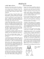
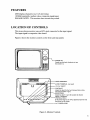
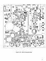
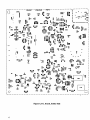
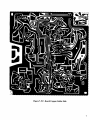
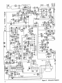
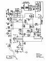
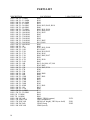
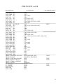
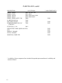
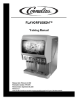
.
C
N
I
,
or
t
i
D on
I
N
eM
H
om
r
C
ch
o
A
on
M
R
"
A 12
#
el
d
o
M
/V
U
8
13
SB
SERVICE MANUAL
Contents
SAFETY PRECAUTIONS ............................................................................................................ 2
FEATURES .................................................................................................................................... 3
LOCATION OF CONTROLS ....................................................................................................... 3
GENERAL INFORMATION ........................................................................................................ 4
Figure 5, P.C. Board, Component Side ......................................................................................... 5
Figure 6, P.C. Board, Solder Side .................................................................................................. 6
Figure 7, P.C. Board Copper, Solder Side ..................................................................................... 7
Figure 8, Schematic Diagram ........................................................................................................ 8
Figure 9, Power Supply Schematic ................................................................................................ 9
PARTS LIST ................................................................................................................................ 10
CAUTION
Before servicing the chassis, read the "Safety Precautions" section in this manual.
1
PREFACE
SAFETY PRECAUTIONS
SAFETY INSPECTION
Operation of the monitor outside of its cabinet or
with its back removed introduces a shock hazard.
Service should only be performed by those who
are thoroughly familiar with the precautions
necessarry when working on high voltage
equipment.
1. Inspect all wire harness assemblies to make sure
that the wires are not pinched or that nothing is
lodged between the chassis and other metal parts.
Exercise care when servicing this chassis with
power applied. Many voltage and video input
terminals are exposed which, if carelessly contacted,
can cause serious shock or result in damage to the
chassis. Maintain interconnecting earth ground
between the chassis, picture tube (CRT) dag, and
PCB ground when operating the chassis.
Certain High Voltage failures can increase X-ray
radiation. The monitor should not be operated with
HV levels exceeding the specified rating for their
chassis type. The maximum operating HV specified
for the chassis used in these receivers is 12KV +1
and -2KV at zero beam current with a line voltage
of 120VAC. Higher voltage may also increase the
possibility of failure in the HV supply.
It is important to maintain specified values of all
components in the horizontal and HV circuits and
anywhere else in the monitor that could cause a
rise in HV or operating supply voltages. No
changes should be made to the original design of
the monitor.
To determine the presence of high voltage, use an
accurate high impedance, HV meter connected
between the second anode lead and the CRT dag
grounding device. When servicing the High Voltage
System, remove static charge by connecting a 10K
ohm resistor in series with an insulated wire (such
as a test probe) between the CRT dag and the 2nd
anode lead. Do this BEFORE disconnecting the
AC line cord from the AC recepticle.
The picture tube used in this monitor employs
integral implosion protection. Replace with a tube
of the same type number for continued safety. Do
not lift picture tube by the neck. Handle the picture
tube only when wearing shatter-proof goggles and
after discharging the high voltages completely.
Keep others without shatter-proof goggles away.
2
2. Replace all protective devices such as nonmetallic control knobs, insulating fishpapers,
cabinet backs, adjustment and compartment
covers or shields, isolation resistor-capacity
networks, mechanical insulators, etc.
3. To be sure that no shock hazard exists, a check
for the presence of leakage current should be
made at each exposed metal part connected to
the chassis, such as cabinet metal, screw heads,
knobs and/or shafts, etc. as follows:
a. Plug the AC line cord into a 12VAC recepticle.
(Do not use an isolation transformer during these
checks.) All checks must be repeated with the
AC line cord plug connections reversed. ( A nonpolarized adaptor plug may be used only for the
purpose of these tests.)
b. Measure the current using an accurate leakage
current tester, if available. (We recommend
Standard Equipment Item # 21641.) Any reading
of 0.46A or more is excessive and indicates a
potential shock hazard which must be corrected.
c. If a reliable leakage current tester is not
available, and alternate method of measurement
should be used. Using two clip leads, connect a
1.5K ohm, 10 watt resistor in parallel with a
0.15uf capacitor; all in series with a known earth
ground. Use a VTVM or VOM with 1000 ohms
per volt or higher sensitivity to measure the AC
drop across the resistor. Any reading of 0.35V
RMS or more is excessive and indicates a
potential shock hazard which must be corrected.
Figure 1, Voltmeter
hookup for safety
check
PARTS LIST
DESCRIPTION
RES 1/4W 5% 1 OHM
RES 1/4W 5% 2.2 OHM
RES 1/4W 5% 6.8 OHM
RES 1/4W 5% 47 OHM
RES 1/4W 5% 56 OHM
RES 1/4W 5% 68 OHM
RES 1/4W 5% 75 OHM
RES 1/4W 5% 100 OHM
RES 1/4W 5% 180 OHM
RES 1/4W 5% 220 OHM
RES 1/4W 5% 330 OHM
RES 1/4W 5% 390 OHM
RES 1/4W 5% 510 OHM
RES 1/4W 5% 560 OHM
RES 1/4W 5% 680 OHM
RES 1/4W 5% 1K
RES 1/4W 5% 1.2K
RES 1/4W 5% 1.8K
RES 1/4W 5% 2.2K
RES 1/4W 5% 2.7K
RES 1/4W 5% 3.3K
RES 1/4W 5% 3.9K
RES 1/4W 5% 4.7K
RES 1/4W 5% 5.6K
RES 1/4W 5% 10K
RES 1/4W 5% 12K
RES 1/4W 5% 15K
RES 1/4W 5% 27K
RES 1/4W 5% 33K
RES 1/4W 5% 39K
RES 1/4W 5% 68K
RES 1/4W 5% 120K
RES 1/4W 5% 220K
RES 1/4W 5% 270K
RES 1/4W 5% 330K
RES 1/4W 5% 390K
RES 1/4W 5% 820K
RES 1/4W 5% 1M
RES 1/4W 5% 1.5M
RES 1/2W 5% 1 OHM
RES 1/2W 5% 22 OHM
RES 1W 33 OHM
RES 7W 16 OHM
RES 1/4W 1K VAR
RES 1/5W 100K VAR
RES 1/5W 50K VAR
RES 1/4W 2M VAR
RES 1/4W 10K VAR
10
LOCATION(S)
* ARACHNID PART #
R602
R330
R601
R912
R404, R413, R603, R918
R409
R802, R911, R919
R116, R906, R913
R301, R412
R905
R915
R904
R315, R605
R411, R809
R903
R401
R303, R811, R909
R311, R407
R406, R914, R951
R306, R916
R803, R805, R917
R956
R101, R910
R405
R415, 604, 806, 907, 908
R305, R403
R304, R402, R314
R309
R307
R408, R808
R902
R807, R901
R420
R953
R952
R302
R313, R961
R812
R960
R312
R410
R414
R801
SR801, VR901(contrast)
39539
VR951(brightness)
SR301(vert. height), VR310(vert. hold)
39541
VR102 (focus)
39542
VR601(on/off)
PARTS LIST cont'd
DESCRIPTION
CAP 220uF 10V
CAP 2200uF 10V
CAP 22uF
16V
CAP 33uF
16V
CAP 47uF
16V
CAP 100uF 16V
CAP 220uF 16V
CAP 1000uF 16V
CAP 6.8uF 50V NP HF
CAP 10uF
25V
CAP 2200uF 25V
CAP 1uF
25V
CAP 3.3uF 25V
CAP 4.7uF 25V
CAP 100pF 50V
CAP 220pF 50V
CAP 1000pF 50V
CAP 0.01uF 50V
CAP 0.47uF 50V
CAP 2200pF 50V
CAP 3300pF 50V
CAP 0.01uF 50V
CAP 0.022uF 50V
CAP 0.056uF 50V
CAP 0.068uF 50V
CAP 0.082uF 50V
CAP 0.1uF 50V
CAP 1uF
100V
CAP 47uF
100V
CAP 0.047uF 250V
CAP 0.022uF 400V
CAP 0.01uF 500V
TRANS 3DG1008 or 2SC1815G
TRANS 2SA1015
TRANS 3DX201B or 2SC1008
TRANS BU406 or 2SC2233
TRANS 3DD880 or 2SD880Y
TRANS 2N5551Y
I.C. KA2130A
I.C. KA2201
IND KLN1023
IND 47uH
IND 12.5uH
LOCATION(S)
* ARACHNID PART #
C312
C313
C903, C904
C306
C124, C901, C907
C602, C603, C605
C330, C410, C413, C607, C908
C604, C811
C416
40857
C309, C310, C608, C809, C905
C805
C308
C405
C311, C305, C813
C302, C420, C902, C906
C408
C402, C606, C609
C801, C802, C803, C804, C807, C808, C810
C301
C401
C303, C304
C403
C314, C406
C307, C409
C407
C414
C601, C404
C952
C951, C953
C412
C101
C415
Q802, Q803,Q901, Q903
39544
Q401, Q301, Q804, Q902
Q402
39545
Q403
39546
Q801
Q904,Q951
IC302
39547
IC601
39548
L401
L902
L406
11
PARTS LIST cont'd
DESCRIPTION
DIODE 1N4002
DIODE FF1003
DIODE 1N4148
DIODE 1N4937
DIODE ZENER MTZ7.5VB
LOCATION(S)
D801, 802, 803, 804
D951, D952
D401, D402, D805, D901
D101, D403, D404
D806
H. DRIVE KLN516A
FBT BSH11-N03LB
POWER XFORMR 120V/12V
(22WT003)
T402
T403
T801
FUSE 250V @ 1.5A
F001
* ARACHNID PART #
39549
39550
39551
DEFLECTING YOKE QPH20-90-1203A
CRT
MAIN P.C. BOARD
CRT P.C. BOARD
39552
39553
39554
39555
MONITOR, COMPLETE
39078
* Availability of these components from Arachnid is dependant upon manufacturer's availability and
customer demand.
12
6421 Material Ave.
P.N. 39354 REV A
Rockford, IL 61111
815-654-0212
800-435-8319
FAX 815-654-0447