1
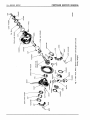
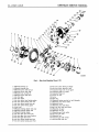
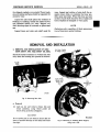
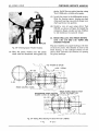
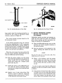
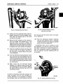
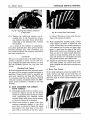
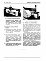
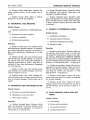
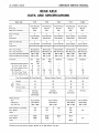
16—REAR AXLE
CHRYSLER SERVICE MANUAL
REAR AXLE
DATA AND SPECIFICATIONS
Rear Axle
C-67
C-68
C-69
C-70
C-300
Type
Gear Type
•Ring Gear Diameter
Semi-Floating
Hypoid
8.25"
Semi-Floating
Hypoid
8.75"
Semi-Floating
Hypoid
8.75"
Semi-Floating
Hypoid
9.62"
Semi-Floating
Hypoid
8.75"
Pinion Bearings
Type
Adjustment
2
Tapered Roller
Shim Pack
2
Tapered Roller
Solid Washer
2
Tapered Roller
Solid Washer
2
Tapered Roller
Solid Washer
2
Tapered Roller
Solid Washer
Differential Bearings
Type
Adjustment
2
2
2
2
2
Tapered Roller
Tapered Roller
Tapered Roller
Tapered Roller
Tapered Roller
Threaded Adjuster Threaded Adj uster Threaded Adj uster Threaded Adj uster Threaded Adjuster
Drive Gear Pinion
Drive Gear Run-Out
Drive Gear and Pinion Backlash
Differential Side Gear Clearance
Matched Sets
.005" Maximum
.006" to .008"
.004" to .012"
Matched Sets
.005" Maximum
.006" to .008"
.004" to .012"
Axle Ratio
Std.
Std.
3.36
37
11
With Standard 3-Speed Trans.
No. Drive Gear Teeth
No. Drive Pinion Teeth...
With PowerFlite
No. Drive Gear Teeth....
No. Drive Pinion Teeth...
T&C
Wgn.
3.91
43
11
3.73
41
11
3.73
41
11
3.54
39
11
Type Recommended Ex. Press. Hypoid
C. g?
Matched Sets
.005" Maximum
.006" to .008"
.004" to .012"
Matched Sets
.005" Maximum
.006" to .008"
.004" to .012"
Matched Sets
.005" Maximum
.006" to .008"
.004" to .012"
T&C
Wgn.
Standard
Standard
Standard
3.54
39
11
3.54
39
11
3.54
39
11
3.54
39
11
Extreme Pressure Hypoid
Ex. Press. Hypoid Ex. Press. Hypoid
Summer
90
90
90
90
Winter
90
90
90
90
Extreme Cold ,
80
80
80
80
3% Pints
(Including
T&C Wagon)
ZVi Pints
(T&C Wagon)
5 Pints
(Limousine)
ZVi Pints
Tapered Roller
Select Shims
.003" to .008"
Tapered Roller
Select Shims
.003" to .008"
Tapered Roller
Select Shims
.003" to .008"
Tapered Roller
Select Shims
.003" to .008"
9%"
9%"
9%"
NA
Capacity
Wheel Bearings
Type
Adjustment
Axle End Play
Road Clearance (full load)
T&C Wagon
Sedan
Tread (Rear)
T&C Wagon
Sedan
8.4"
8.4"
8.4"
8.4"
8.6"
59.62"
59.62"
59.62"
59.62"
60.35"
•Windsor Town and Country Wagon Models use an 8.75 diameter ring gear.
60.75"
NA
60.75"
REAR AXLE—17
CHRYSLER SERVICE MANUAL
ADDITIONAL SPECIAL TOOLS REQUIRED FOR
SERVICING THE REAR AXLE
Tool Number
Tool Name
C-406A
C-430
Wrench—Differential Bearing Adjusting
Dial Indicator Set
C-452
Puller—Companion Flange or Yoke
C-757
C-758-D2
C-784
C-839
DD-807
DD-914-8
DD-914-89
Sleeve—Axle Shaft Oil Seal Installing
Pinion Bearing Pre-load and Cone Angle Setting Gauge
Companion Flange on Yoke Holding—Wrench
Driver—Axle Shaft Inner Oil Seal
Driver—Pinion Oil Seal Installing
Ring—Medium Reducer (use with DD-914-89)
Plate Set—Pinion Bearing Puller Adaptor
DD-921
Wrench—Differential Case Cap Remover and Installer
DD-993
DD-999
Puller—Pinion Oil Seal
Tool—Companion Flange or Yoke Installing
TIGHTENING REFERENCE
Foot-Pounds
AXLE SHAFT NUTS
BRAKE SUPPORT PLATE TO HOUSING MOUNTING BOLT NUTS ..
DIFFERENTIAL CARRIER TO AXLE HOUSING BOLT NUTS
REAR AXLE DRIVE GEAR BOLT NUTS
DIFFERENTIAL BEARING CAP BOLTS
145 (minimum)
35
45
40
90
PINION SHAFT COMPANION FLANGE NUT
C-67
240 (minimum)
C-68, C-69, C-70, C-300
250 (minimum)
18—REAR AXLE
CHRYSLER SERVICE MANUAL
LOCKWASHER
FLANGE
GUARD
OIL SEAL
BOLT AND LOCKWASHER
BEARING CONE -
ADJUSTER LOCK
<7 ^
\
CARRIER CAP
ADJUSTER
BEARING
PINS
NUT
OIL SLINGER
BEARING CUP
PINION SHAFT
SPACER
CARRIER
PINION SHAFT
BEARING CUP
FILLER PLUG
DRIVE GEAR
AND PINION
BEARING ADJUSTING SHIMS
BEARING CONE
DRIVE PINION ADJUSTING WASHER
PINION THRUST WASHER
BOLT AND
LOCKWASHER
DIFFERENTIAL PINIONS
BEARING CONE
NUT
NUT LOCK
PINION SHAFT
DIFFERENTIAL CASE
PINION THRUST WASHER
BOLT
SIDE GEAR
SIDE GEAR THRUST WASHER
BOLT AND LOCKWASHER
SIDE GEAR
BEARING CONE
THRUST BLOCK
BEARING CUP
PINION THRUST WASHER
ADJUSTER
DIFFERENTIAL PINIONS
ADJUSTER LOCK
PINION THRUST WASHER
BOLT AND LOCKWASHER
PINION SHAFT BLOCK
CARRIER CAP
SIDE GEAR THRUST WASHER
LOCKWASHER
CASE CAP
BOLT
Fig. 2—Rear Axle (Exploded View) C-67 PowerFlite Equipped Cars (Except Town
and Country Wagon)
52x614C
LOCK WASHER.
FLANGE
NUT
OIL SLINGER
GUARD
BOLT AND LOCKWASHER
ADJUSTER LOCK
OIL SEAL
CARRIER CAP
BEARING CONE
ADJUSTER
DRIVE GEAR AND PINION
BEARING CUP
BEARING CONE WASHER
PINION SHAFT
V,
DRIVE PINION
ADJUSTING
WASHER
BEARING ADJUSTING SPACER
BEARING CONE
SIDE GEAR THRUST WASHER
PINION THRUST WASHER
DIFFERENTIAL PINIONS
PINION THRUST WASHER
SIDE GEAR
BOLT AND LOCKWASHER
BEARING CONE
BEARING CUP
I
/
BEARING CONE
NUT LOCK
DIFFERENTIAL CASE
ADJUSTER
PINION SHAFT
BOLT A N D LOCKWASHER
SIDE GEAR
THRUST BLOCK
CARRIER CAP
PINION THRUST WASHER
ADJUSTER LOCK
DIFFERENTIAL PINIONS
PINION THRUST WASHER
PINION SHAFT BLOCK
SIDE GEAR THRUST WASHER
BOLT-
BOLT AND LOCKWASHER
or
LOCKWASHER
LOCI
52x600A
Fig. 3—Rear Axle (Exploded View) C-68, C-69 including C-67-C-68 Town and Country Wagon
CHRYSLER SERVICE MANUAL
REAR AXLE—21
Section II
REAR AXLE
1. DESCRIPTION
A modification has been made on the differential carrier assembly on the New Yorker eliminating the axle drive gear thrust screw and
thrust pad. This change has also been made on
Crown Imperial cars produced later in the
model year. A Belleville lockwasher is now being used in conjunction with the drive pinion
flange nut on all Chrysler axles replacing the
slotted nut and cotter pin formerly used, permitting a more accurate torque setting of the
drive pinion flange nut and allowing more accurate pre-loading of the drive pinion bearings.
These washers have a .024 to .031 inch "dish"
and are marked with white paint on the "convex" side of the washer. When installing the
Belleville washer the "convex" or painted side
of washer should face towards the nut.
A Belleville washer can also be used with a
slotted type nut providing the tightening specification for the Belleville washer is used.
The tightening specifications for use with the
Belleville type washer are 240 minimum footpounds torque for the Windsor DeLuxe Models
and 250 minimum foot-pounds torque for the
New Yorker and Imperial Models.
NOTE
The thread form on the differential bearing adjusters on the 1955 New Yorker and Custom
Imperial Models (except for the Croivn Imperials) are changed and are not interchangeable with the 195U adjusters.
The axles, as shown in Figures 1, 2, 3 and 4,
though different in design, are of the semifloating type with a hypoid ring gear and pinion.
The differential, drive pinion and axle shafts are
carried on adjustable taper roller bearings. The
rear cover is welded to the axle housing, necessitating the removal of the differential assembly
in order to adjust the differential bearings. To
insure quiet, smooth operation, the ring gear
and pinion are serviced only in matched sets.
2. CLEANLINESS
Cleaning parts after disassembly is a very im-
portant procedure. Parts must be kept clean all
through assembly. Tiny metal chips, bits of
dirt, or foreign particles mixing with the lubricant are liable to cause excessive wear or axle
failure if not cleaned from parts and housing.
Whenever the rear axle carrier assembly is
removed from car for overhauling, the assembly and parts (except bearings) should be
cleaned in a suitable cleaning solvent to remove
dirt and hardened lubricant from the assembly
before inspection. Bearings should be soaked in
clean kerosene or any other good quality bearing cleaning fluid.
NOTE
Gasoline should never be used for cleaning parts
since parts cleaned with gasoline have a tendency to rust.
The bearings should be immersed in clean
solvent and rotated by hand until clean. After
cleaning, blow dry with controlled compressed
air.
3. INSPECTION
The inspection of rear axles consists of visual
inspection for damaged or excessive parts wear.
Parts that are worn, pitted or scored must be
replaced. Scratches or rough spots on mating
surfaces should be stoned-out if possible. If
spots or scratches cannot be stoned-out without
damaging part, part should be replaced. Bearings and bearing cup should be examined for
cracks, chips and discoloring due to overheating
or excessive wear. Bearings should be lubricated and assembled in bearing cup, rotated by
hand to check for roughness, and then wrapped
in cloth and stored until ready for use.
Axle housing should be inspected for broken
welds, missing or loose housing to carrier attaching bolts, damaged threads, bent or cracked
housing. Inspect spring seat welds to make sure
they are not broken or loose. Repair or replace
as required.
Drive gear and pinion should be inspected
CHRYSLER SERVICE MANUAL
22—REAR AXLE
52x608A
Fig. 4 - Rear Axle (Exploded View) C-70
1—Differential
2—Differential
3—Differential
4—Differential
5—Differential
6—Differential
7—Axle drive
8—Axle drive
bearing cup
bearing cone
pinion shaft lock pin
pinion shaft—long
case cap lock pin
pinion shaft—short
gear
pinion
9—Axle drive pinion
10—Axle drive pinion
11—Axle drive pinion
12—Axle drive pinion
13—Carrier caps
14—Differential
15—Differential
16—Differential
17—Axle drive
18—Axle drive
19—Axle drive
20—Axle drive
21—Axle drive
inner bearing washer
bearing cone—rear
bearing cup—rear
bearing spacer
bearing adjuster lock screw
bearing adjuster lock
bearing adjuster
gear thrust screw pad
gear thrust screw check-nut
gear thrust screw
pinion bearing cup—front
pinion bearing cone—front
22—Axle drive pinion bearing oil slinger
23—Axle drive pinion bearing oil seal
24—Companion flange and oil seal guard
25—Companion flange nut washer
26—Companion flange nut
27—Carrier cap stud
28—Carrier
29—Filler plug
30—Differential bearing cap stud nut and lockwasher
31—Differential pinion thrust washer
32—Differential pinions
33—Differential pinion shaft block
34—Rear axle drive shaft thrust block
35—Differential side gear
36—Differential case cap
37—Differential gear thrust washer
38—Axle drive gear bolts
39—Differential case
40—Axle drive gear bolt nut lock
41—Axle drive gear bolt nuts
CHRYSLER SERVICE MANUAL
REAR AXLE—23
for chipped, cracked or worn teeth. Thrust washers and mating surfaces should be inspected for
excessive wear.
Inspect the axle shaft splines for evidence of
twisting or cracking. Check axle shaft keyway
and threaded section for wear. Replace any
shaft showing signs of torsional or spline damage.
Inspect inner and outer axle shaft seals for
wear. Inspect seal surface of axle shaft for excessive wear, nicks, or scratches that may possibly cause seal leaks. Wheel hub boss and seal
surface of axle shaft should be free of nicks and
burrs. Replace all damaged or worn parts.
NOTE
Replacing seals regardless of their appearance
is good insurance against leakage.
REMOVAL AND INSTALLATION
4. REMOVAL AND INSTALLATION OF AXLE
DRIVE SHAFT AND AXLE SHAFT OIL SEAL
OIL SEAL STAKED
IN THREE PLACES
Should it become necessary to overhaul the rear
axle, drain the housing and proceed as follows:
PULLER
TOOL!
REAR WHEEL
BRAKE AXLE
SHAFT OIL
SEAL
SEAL
PROTECTING
SLEEVE
54x660
Fig. 5—Removing Rear Hub
a. Removal
(1) Jack up car and remove wheel, hub and
drum assembly, using wheel puller set
Tool C-675, as shown in Figure 5.
CAUTION
Do not strike end of axle shaft to loosen hub because of possible damage to axle shaft and roller
bearings.
46x105 A
Fig. 6—Removing or Installing Brake Support,
Using Tool C-757
CHRYSLER SERVICE MANUAL
24—REAR AXLE
(6) Remove the axle shafts and bearings from
the housing, using Tool C-499, as shown in
Figure 7.
CAUTION
Do not allow the axle shaft to drag on the inner
oil seal when removing axle from housing. The
inner diameter of the oil seal is designed with
a feather edge to hug the shaft snugly to prevent oil leak. If this edge is enlarged or damaged in any way, the efficiency of the seal will
be impaired.
REAR AXLE SHAFT
46x140
Fig. 7—Removing Axle Drive Shaft and Bearing,
Using Tool C-499
If axle shaft bearings are to be replaced, perform operation in Step (7).
(7) Remove bearings from the axle shafts, using bearing puller Tool C-293-C, as shown
in Figure 8.
(2) Block brake pedal so it cannot be depressed.
(3) Disconnect brake line at wheel cylinder.
(4) Remove the rear axle drive shaft key and
install the special sleeve Tool (C-757) in
the axle bearing outer oil seal before removing the brake support from the axle
housing, as shown in Figure 6,
(5.) Remove the shims from each end of the
axle housing. Shims should be kept separate so that they can be reinstalled in the
same position as they came off the axle
housing, so as to keep the axle shaft thrust
block centralized in the differential assembly.
REAR AXLE SHAFT
INNER OIL SEAL
TOOL'
49x713
Fig. 9—Removing Axle Shaft Inner Oil Seal
(Tool C-637)
(8) Remove the axle shaft inner oil seal from
housing, using Tool C-637, as shown in
Figure 9.
(9) Remove outer oil seal from support plate
by driving the seal out of plate with driver,
Tool 0-839.
Cleanliness and inspection are vital factors to
be remembered when overhauling or repairing
a rear axle assembly.
6X57
Fig. 8—Removing Bearing from Axie Drive Shaft
1-Axl« drive shaft
2-Jool C-293-C
3-Bearing
Clean aU parts after disassembly and keep
them clean throughout assembly*. Metal chips,
or particles of grit or dirt that may drop into
the lubricant, will cause excessive wear and
eventually cause failure of the axle.
REAR AXLE—25
CHRYSLER SERVICE MANUAL
NOTE
New oil seals should be installed whenever seals
are removed from axle housing and brake support plate.
REAR AXLE SHAFT
BEARING CONE AND ROLLERS
b. Installation
Always inspect all parts before assembly and
replace those that are worn or scored. Check
for and remove any burrs, nicks, scratches, or
rough spots on mating surfaces of replacement
parts that may have been caused by rough
handling.
(1) Install the rear axle drive shaft inner oil
seal in housing, using special drift Tool
C-241 for Model C-70.
TOOL
49x714
Fig. 11—Installing Axle Shaft Bearing (Tool C-158)
(4) To install the axle shaft, first replace the
bearing on axle shaft with special Tool
C-158 (Fig. 11) and moderately lubricate
axle bearings with hypoid lubricant. Carefully insert the axle shaft in the housing,
making sure the shaft and differential side
gear splines align.
(5) Install the axle drive shaft outer bearing
cup with special driver Tool C-413 (Fig.
12).
(6) Install shims in same manner as removed
to maintain the central position of axle
shaft thrust block.
Fig. 10—Installing Axle Shaft Oil Seal (Tool C-241)
(2) Install outer oil seal in brake support plate.
Secure seal in place by staking in three
places, as shown in Figure 6.
(3) Leather seals should be prepared for installation by soaking them in light engine
oil for 30 minutes.
Before installing the axle shaft in housing,
examine the bearing surface of the bearing cups
for wear and pits, also the surface of the axle
shaft on which the oil seal wipes to make sure
that it is smooth and free from tool marks and
burrs. If necessary, dress down the surface of
the shaft with a stone or fine emery cloth to
make a smooth bearing surface for the oil seal.
NOTE
Stone or emery polish lines should run around
and not along shaft.
(7) Install special sleeve Tool C-757 in the axle
bearing outer oil seal, before mounting
brake support to the axle housing (Fig. 6),
to protect seal from being damaged by axle
shaft keyway during installation.
(8) Clean mating surfaces of axle housing
flange and brake support.
Fig. 12—Installing Axle Drive Shaft Bearing Cup
(Tool C-413)
26—REAR AXLE
CHRYSLER SERVICE MANUAL
(9) Install new gaskets.
(10) Install brake support plates and tighten
attaching nuts to 35 foot-pounds torque.
(11) Install axle shaft keys.
(12) Connect brake lines to brake cylinder, unblock brake pedal and bleed brake lines.
(13) Check the axle shaft end play with dial
indicator to make sure it comes within
.003 to .008 inch limits, as outlined in Paragraph 6.
(14) Install wheel hub and drum assembly.
Tighten axle shaft nuts to a minimum
of 145 foot-pounds torque. Install new cotter keys and hub caps.
assembly. If break is more than 8 inches from
splined end of shaft, it will be necessary to remove inner oil seal and snare inner end of axle
drive shaft out through housing with a loop.
CAUTION
To avoid damage to rear axle carrier assembly,
the oil must be drained from the differential
housing and the housing cleaned to remove chips
and grit before installing the new axle shaft.
(1) Replace axle shaft and check rear axle end
play, as outlined in Paragraph 6.
(2) Replace wheel hub and drum assembly and
tighten axle shaft nuts to a minimum of
145 foot-pounds torque.
6. SETTING AXLE SHAFT END PLAY
Rear axle shaft end play is adjusted by the use
of adjusting shims (Fig. 13) that are bolted
between the axle housing ends and the brake
support plates. The shims are available in thicknesses of .005, .010, .0125, .015 and .030 inch.
The correct axle end play is .003 to .008 inch.
One or more shims may be required to obtain
correct end play.
51x866
Fig. 13—Axle Shaft Bearing Adjusting Shims
Checking Axle Shaft End Play
(15) Refill the axle housing and carrier assembly with Extreme Pressure Hypoid Lubricant, as outlined in Lubrication Section.
(16) Check and refill master cylinder.
(17) Check and adjust brake shoes.
(18) Remove jack from car.
5. REMOVING BROKEN END OF AXLE
DRIVE SHAFT
Remove wheel, drum and axle drive shaft, as
outlined in Paragraph 4. If break is less than
about 8 inches from splined end of shaft, it will
be necessary to remove differential and carrier
(1) Preparation for setting axle shaft end play
consists of removal of axle drive shafts. It
is not necessary to remove the bearing
cones from the axle drive shafts unless they
are to be replaced. Clean parts after disassembly, and inspect bearing cups, cones,
and rollers for signs of surface failure.
(2) The axle drive shaft thrust block has an
elongated hole to allow the block approximately y± inch total lateral motion in the
assembly. The thrust block must be located
so that the elongated hole is approximately
centered on the long differential pinion
shaft.
To adjust the axle end play, the operation can
be started from either side of the axle housing.
These instructions will be confined to the case
of starting at the left side.
Install the left axle drive shaft and bearing
cone assembly (without lubricant). Drive in
the bearing cup as far as it will go, using Tool
C-413, in order to prevent damage to the axle
housing. This will thrust the block as far to the
right as it can go, as shown in "A," Figure 14.
CHRYSLER SERVICE MANUAL
(3) If the left bearing cup is now withdrawn
about MJ inch, the thrust block will be approximately centered on the differential
pinion shaft. Axle operation is not affected
by mislocation of the thrust block unless
the block bears against the differential
pinion shaft, in which case the end play of
the left and right axle shafts may be different, and wheel thrust will be imposed
upon the differential bearings, a condition
that should be avoided.
With the left bearing cup remaining at its
innermost position, as shown in Figure 14, lay
a straightedge across the end of the axle housing. Measure the distance from the straightedge
to the bearing cup face, to the nearest %4 inch.
The example shown in "B," Figure 14, shows a
measurement of %<> inch.
REAR AXLE—27
One eighth inch minus the above measurement gives the thickness of shims required at
the left end of the housing to center the thrust
block. For the above example, a shim y32 inch
thick would center the thrust block. A .030 inch
shim is close to this thickness, but a good practice is to use about a .020 inch shim which is less
shim than the thickness required for centering
the thrust block.
(4) Remove the left axle shaft, grease the bearing, reinstall the shaft and bearing. Using
the correct thickness of shims or shim as
determined in Step (3), install the left
brake support plate. The bearing cup
should not be driven all the way in during
this operation. As the brake support plate
is drawn up tight, it will push the bearing
cup in to the correct position. This completes the work on the left axle.
DIFFERENTIAL PINION SHAFT
51x187
Fig. 14—Adjusting Axle Shaft End Play
28—REAR AXLE
CAUTION
Use clean shims. Clean mating surfaces. Presence of rust or grit will result in incorrect
measurement.
(5) Install the right axle drive shaft and bearing without lubricant. Bearing should be
clean and dry. Using Tool C-413, drive the
bearing cup in as far as it will go, while
rotating the axle shafts to seat both bearings properly. If the proper procedure has
been followed, as outlined in Step (4), the
left bearing cup will be up firmly against
the left brake support plate, and the right
bearing cup, bearing cone, right axle shaft,
thrust block, left axle shaft and left bearing cone, will move as a unit, until the left
bearing is seated. It is important that the
axle shafts be rotated during this operation. Now the end play in the bearings will
be zero, and the rotation of the axle shafts
will require more effort. The right bearing
cup should then protrude beyond the housing end.
Leaving .010 inch out of the left shim, as
described in Step (3), will help to assure that
the right bearing cup will protrude beyond the
housing end face.
(6) Hold a straightedge firmly against the
outer face of the right bearing cup. Using
a set of feeler gauges, measure accurately
the distance between the housing face and
the straightedge. This measurement gives
the thickness of the shim that would give
zero end play if it were used in the assembly. The shim thickness to be used is obtained by adding .003 inch to the above
measurement. If this gives a thickness that
cannot be built up from existing shims,
use the next larger shim combination. This
insures that the end play will be greater
than .003 inch.
For an example of end play setting, assume
the right bearing cup face protrudes .038 inch
beyond the end face of the housing. Shim thickness required for .003 inch end play is .038 inch
+ .003 inch = .041 inch. This cannot be obtained with existing shims, so .0425 inch is
used, which is obtained with one .030 inch and
one .0125 inch shim. The end play is then .0425
inch minus .038 inch, equals .0045 inch.
(7) Remove the right axle shaft and lubricate
CHRYSLER SERVICE MANUAL
the bearing. Install axle shaft, bearing and
shim pack as determined in Step (6), and
complete the assembly.
(8) If the dial indicator shows less than .003
inch, or more than .008 inch end play, remove the brake support plate and oil seal,
and add or remove shims, as required, to
obtain the desired axle shaft end play.
CAUTION
When adjusting axle shaft end play, equal thicknesses of shims should be removed or installed
on both sides of the axle housing to maintain
the centralized position of the axle shaft thrust
block.
After the axle shaft end play has been
checked or corrected, install the brake drum and
wheel assembly. Tighten axle shaft nuts to a
minimum of 145 foot-pounds torque. Install cotter keys and remove jack from car.
7. REMOVAL AND INSPECTION OF
DIFFERENTIAL AND CARRIER ASSEMBLY
a. Removal
(1) Remove wheel hub and drum assembly and
rear axle shafts, as outlined in Paragraph
4, and proceed as follows:
(2) Disconnect rear universal joint and drop
propeller shaft.
NOTE
All accumulation of grit, dirt and other foreign
matter, deposited on the differential and carrier
assembly around the attaching bolt nuts, should
be cleaned off before the assembly is removed
from the housing to prevent them falling into
the housing, gears, or bearings, when the assembly is removed.
b. Inspection
(1) Make sure the companion flange or yoke
nut is tight and has not moved from its
original position.
(2) Check the backlash between the drive gear
and pinion gear. See Figure 15. (Backlash
should not be less than .006 inch or more
than .008 inch.)
(3) Inspect the surfaces of the drive gear and
CHRYSLER SERVICE MANUAL
REAR AXLE—29
SCRIBE MARKS
PUNCH
MARKS
52x371
Fig. 16—Marking Bearing Caps and Adjusting Nuts
Fig. 15—Checking Backlash Between Drive Gear
and Pinion (Tool C-430)
pinion teeth for nicks, burrs, scoring or
other damage (Drive gear and pinion are
replaceable in sets only.)
(4) Check tightness of drive gear to differential case bolts. Tighten if necessary.
(5) Check drive gear runout with gauge C-430.
Runout should not be more than .005 inch.
(6) Check differential bearing pre-load and
backlash, as outlined in Paragraph 22.
NOTE
Careful inspection of pinion bearing pre-load
will assist in determining cause of noisy axle.
Improper drive pinion position ivill cause a
noisy axle.
8. REMOVING DIFFERENTIAL CASE AND
DRIVE GEAR ASSEMBLY FROM CARRIER
(All Models)
Refer to Figures 2, 3 and 4. Disassemble the
differential case assembly as follows:
(1) Mount the carrier assembly in stand. Mark
both differential bearing adjusters and
caps, so they may be reinstalled in approximately the same position at assembly (Fig.
16).
NOTE
Bearing caps must NOT be interchanged. They
are lined-bored with the carrier housing when
manufactured.
(2) Remove the bearing cap bolts, caps, adjusting nuts and bearing cups and lift the differential case and drive gear assembly out
of carrier.
NOTE
Clean drive gear, bearings, bearing cap, drive
pinion and inside of carrier assembly, as outlined in "Cleanliness," Paragraph 2.
9. DISASSEMBLY AND INSPECTION OF
CAGE-TYPE DIFFERENTIAL
a. Removal
(1) Place differential case and drive gear assembly on bench, bend down locking tabs
and remove drive gear to case attaching
nuts and bolts.
(2) Using a fiber hammer, tap drive gear off
differential case.
(3) To check differential case for runout,
mount the differential case, bearings and
cup assembly in carrier. Install bearing
caps and adjusters and adjust excessive
CHRYSLER SERVICE MANUAL
30—REAR AXLE
51x199
49x722
Fig. 17—Removing Differential Side Carrier Bearings
(Tool C-293-C)
play from bearings with adjusters. Mount
dial indicator on carrier mounting surface
and check drive gear mounting flange runout. Runout should not exceed .005 inch. If
there is more than .005 inch runout the
differential case should be replaced.
(4) Inspect bolt holes for wear or out-ofround; if worn or out-of-round, replace
case.
(5) Mount differential case assembly in a
heavy vise, using copper jaws.
(6) Install Tool C-293-C on bearings, as shown
in Figure 17, and remove bearings from
differential case.
b. Inspection
(1) Check the clearances between the side
gears and thrust washers. Clearance should
be .004 to .012 inch. To do this, use two
feeler gauge blades. Slide the blades between side gear and thrust washer—one
blade on each side of gear hub, as shown in
Figure 18. Try two .004 inch blades—they
should go in. Then, try two .013 inch blades
—these should not go in. Now, check the
opposite side gear the same way.
(2) Remove differential pinion shaft lock pin
from differential case, push out pinion
shaft and remove differential side gears.
When reassembling the ground surfaces
Fig. 18—Checking Differential Side Gear Clearance
of the thrust block should be turned toward
the axle shaft. Clean all parts thoroughly
in a suitable solvent and dry with compressed air. The bearings should also be
immersed in clean solvent and rotated until clean.
(3) Check differential side gear and pinion
teeth, bores and spherical back of pinions,
pinion (cross) shaft, thrust washers and
thrust surfaces inside the differential case
for wear or damage. If any of the above
mentioned parts are worn so that they will
affect the operation of the differential, they
should be replaced.
(4) Inspect the fit of the differential side gears
in the hub of the differential case. If they
are excessively loose, the gears or case
should be replaced.
(5) Examine the surfaces of differential case
cone and roller bearings, and the bearing
cups, for pitting and wear. Assemble cups
in bearings and rotate. If the bearings are
rough or drag on rotation, the bearing
rollers may have a flat spot. If so, the bearing should be replaced.
(6) Make sure the oil passages in the differential carrier are clear, clean and unobstructed.
CHRYSLER SERVICE MANUAL
REAR AXLE—31
LOCK PIN
DRIVE OUT
HOLES
52x377
52x375
Fig. 19—Checking Ring Gear Mounting Flange Runout
NOTE
Whenever a differential carrier assembly is removed for rebuilding, due to bearing or other
failure, care must be taken to see that all foreign mutter, such as grit, dirt, metal particles,
etc., are removed from the carrier.
10. DISASSEMBLY AND INSPECTION OF
BARREL-TYPE DIFFERENTIAL WITH
BOLTED-ON CASE CAP
a. Disassembly
(1) Place differential case and drive gear assembly on bench, bend down locking tabs
and remove drive gear to case attaching
nuts and bolts.
(2) Use a fiber hammer to tap drive gear off
differential case.
(3) Clean around differential case flange to allow for checking face runout.
(4) Mount the differential case in the carrier.
Assemble bearings, the adjusting nuts and
bearing caps on carrier. Adjust and remove excessive play from the bearings.
Mount a dial indicator on the carrier
mounting face and check the ring gear
mounting flange for runout, as shown in
Figure 19.
NOTE
If there is more than .005 inch runout during
the above check, the differential case must be
replaced.
Inspect the bolt holes in the ring gear mounting flange for wear or out-of-round. If the bolt
LOCK PIN
Fig. 20—Removing the Differential Pinion Shaft
Lock Pins
holes are out-of-round, the ring gear will creep
on the case.
(5) Remove the differential case from the carrier.
(6) Fit Number 18 plates behind bearings and
pull off the differential bearings, using
Tool C-293, as shown in Figure 17. Remove
the differential bearing spacers.
(7) Remove the differential cap to case bolts,
and tap the cap lightly with a soft hammer
to remove.
(8) Remove the three differential pinion shaft
lock pins by driving them out of the case
with a hammer and punch, as shown in
Figure 20.
(9) Drive the long pinion shaft out of the differential case, using a brass drift and hammer. NOTE: This shaft can be identified as
having only 1 retaining pin.
(10) Lift out the rear axle drive shaft thrust
block.
(11) Drive the short pinion shafts out of the
case, and lift out the pinion shaft block.
NOTE: The short pinion shaft sides of the
block are punch marked for identification.
(12) Lift put the differential pinion gears, slide
gears and thrust washers.
b. Cleaning and Inspection
(1) Clean all parts thoroughly in a suitable solvent and blow dry with compressed air.
Remove any chips or foreign material from
32—REAR AXLE
CHRYSLER SERVICE MANUAL
the carrier housing. Inspect all machined
surfaces for nicks, burrs or scratches. Inspect the thrust shoulders in the carrier
housing (bearing cups) to make sure there
are no burrs on them. The thrust shoulder
must be flat so that the bearing cups will
seat properly. Check the differential case
for cracks, fractures, distortion or damage.
Install a new case if necessary.
(2) The bearings should be immersed in clean
solvent and rotated by hand until clean.
After cleaning, blow dry with compressed
air.
CAUTION
46X200
Do not spin the bearings with air pressure
when blowing them dry, as damage to the bearings may result from this practice.
Pig. 22—Removing Differential Case Cap,
Using Tool DD-921
(3) Check the bearings for roughness, or brin-
NOTE
elling. The bearings must run free and show
no indication of roughness or wear.
(4) Examine the bearing cups for pitting, scor-
ing or wear. Inspect all gears for chipped
or worn gear teeth. Check the fit of the differential side gears on the axle shaft
splines and the differential gears on the
pinion shafts. Check the thrust washers
for wear and replace if necessary.
Whenever a differential carrier assembly is
removed for rebuilding due to bearing or other
failure, care must be taken to see that all foreign matter, such as grit, dirt, metal particles,
etc., are removed from the carrier.
11. DISASSEMBLY AND INSPECTION OF
BARREL-TYPE DIFFERENTIAL WITH
SCREWED-ON CASE CAP
Remove drive gear from differential case as outlined in Paragraph 10 and proceed as follows:
(1) Mount the flange of the differential case in
a vise equipped with copper jaws.
(2) Remove differential bearings with puller.
On Model C-70 use Number 83 adapter and
Number 41 plug, puller set Tool DD-914.
Figr21—Removing Differential Case Cap Lock Pin
(3) Remove the differential case cap locking
pins by center punching and drilling, as
shown in Figure 21. Remove shell of pin
left in hole with a punch. The differential
case cap is .001 to .002 inch larger than the
differential case body in which it fits. The
case must be expanded by heating for easy
removal of case cap. The case will be damaged, if any attempt is made to remove cap
without heating.
CHRYSLER SERVICE MANUAL
Heat the outside of the case (not cap) with a
torch. Keep the flame moving around the case
to assure even heating. Try a piece of ordinary
soft solder on the case, from time to time. When
the solder starts to melt at approximately 360
to 400 degrees F., the case will be as hot as it
can get without damaging the thrust washers.
When the case is just hot enough to melt soft
solder loosen cap with a blunt drift and a heavy
hammer and quickly unscrew the cap from the
case, with Tool DD-921, as shown in Figure 22.
The parts can now be immersed in oil to cool
for subsequent handling.
(4) Remove the three different pinion shaft
lock pins by driving them out of the case
with a hammer and punch, as shown in
Figure 23.
(5) With a drift and hammer, drive the long
pinion shaft out of the case. Then, remove
the thrust block. Now, drive the short pinion shafts out of the case and lift out the
pinion shaft block.
(6) Remove the differential pinions, side gears
and thrust washers from the case.
12. ASSEMBLY OF CAGE TYPE DIFFERENTIAL
When installing drive gear to differential case,
be sure the holes in drive gear are properly
lined up with the holes in the differential case
before pressing the gear on the case.
REAR AXLE—33
(1) Press gear on case. Install attaching bolts
and tighten to 40 foot-pounds torque.
(2) Install the differential side gears with their
thrust washers, the differential pinions
and their thrust washers, and the differential pinion shaft. Check the differential side
gear clearance (Fig. 18).
If clearance cannot be obtained with the old
thrust washers and gears, install necessary new
parts to obtain the correct clearance.
(3) After clearance has been obtained, remove
pinion shaft gears and thrust washers.
Coat the shaft and other parts moderately
with Extreme Pressure Hypoid oil and reassemble parts in differential case.
(4) Line up the locking pin hole in the pinion
shaft. Enter the shaft in pinion shaft hole
in case. Assemble side gears and thrust
washers in hub of case and pinion gears,
thrust block spacers and thrust block on
shaft. Press shaft into case.
(5) Install pinion shaft locking pin in case and
press pin in place, peening the metal of the
case over the ends of pin to retain pin in
place.
(6) Install differential bearings on differential
case, using Tool DD-1004.
(7) Install bearing cups on bearings and
mount the differential gear assembly in
carrier.
(8) Assemble bearing caps and bearing adjusting nuts in carrier and check the differential case runout. After bearing caps have
been brought up against bearing cups,
mount a dial indicator, with the pointer
resting against the back face of the ring
gear. As the drive gear and case is rotated,
the runout should not exceed .003 inch. If
runout exceeds .005 inch, the differential
case should be replaced.
13. ASSEMBLY OF BARREL TYPE DIFFERENTIAL
WITH BOLTED-ON CASE CAP
Fig. 23—Removing Differential Pinion Shaft Lock Pins
(1) If new differential side gears are to be
installed, place a new thrust washer over
hub of differential side gear and lay in
position in the differential case.
CHRYSLER SERVICE MANUAL
34—REAR AXLE
DIFFERENTIAL PINION SHAFT—LONG
1/16 INCH APPROXIMATE
LOCK PIN HOLES
SHOULD BE
ALIGNED
52x623
HOLES FOR
DIFFERENTIAL
PINION SHAFTS
—SHORT
Fig. 25—Tightening Differential Case Cap Screws
52x384
Fig. 24—Positioning the Long Pinion Shaft in Case
(2) Line up the locking pin hole in the long
pinion shaft with the hole in the differential case pinion boss (opposite boss has no
pin hole). Drive the pinion shaft in case
until it protrudes about 1/i6 inch on the
inside of case, as shown in Figure 24.
(3) Place a pinion thrust washer on the pinion
so that the concave side faces the pinion.
Install the pinion and thrust washer on the
end of the shaft that protrudes through
case. Tap shaft in case, while holding pinion up against case, until end of shaft is
even with edge of pinion.
(4) Insert the pinion shaft block with punch
marked sides facing the short shaft holes.
Install the axle drive shaft thrust block
and continue to drive the shaft through
the pinion shaft block and rear axle drive
shaft thrust block.
(5) Install the opposite pinion and thrust
washer. Drive the shaft into final position
in case, making sure locking pin holes are
lined up.
(6) Drive one of the short pinion shafts into
either of the remaining holes until the
shaft protrudes about %« m c n o n the
inside of case. (Be sure the lock pin holes
line up.) Install pinion and thrust washer
and continue to drive shaft until shaft
enters hole in the pinion shaft block. Install the other short shaft, washer and
gear in the same manner.
(7) Lock the three pinion shafts into the case
by installing three new locking pins in the
holes, driving the pin ends approximately
Ym inch below machined surface of case.
(8) Assemble the thrust washer and differential side gear in the cap. Using the attaching cap screws as guides, position cap on
differential case, and tap into position with
fiber hammer.
(9) Tighten cap screws to 35 foot-pounds
torque as shown in Figure 25.
(10) Install ring gear and tighten mounting
bolt nuts to 40 foot-pounds torque. Lock
the nuts by bending locking tabs.
(11) Slide the differential bearing spacers over
the hubs (if so equipped). Install the bearings on the case, using Tool DD-1005, as
shown in Figure 26.
(12) Place the differential bearing cups over
the bearings. Install complete assembly in
the carrier housing.
(13) Seat the adjusting nuts in the pedestals
of the carrier housing and install the caps
and bolts. NOTE: Be sure the caps are on
the same side from which they were removed.
(14) Mount a dial indicator, with the pointer
resting against the back face of the ring
gear and check the runout. Runout should
be true within .005 inch, as shown in Figure 19.
CHRYSLER SERVICE MANUAL
REAR AXLE—35
USE BALL END PUNCH
TO PEEN METAL OVER
TOP OF PINS—PEEN
METAL O N DRIVE GEAR
SIDE OF PIN HOLE
51x164
52x385
Fig. 26 — Installing Differential Bearings
14. ASSEMBLY OF BARREL TYPE DIFFERENTIAL
WITH SCREWED-ON CASE CAP
(1) If new differential side gears are to be installed, place a new thrust washer over hub
of gear and lay in position in the differential case.
(2) Line up the locking pin hole in the long
pinion shaft with the hole in the differential case pinion boss (opposite boss has no
locking pin hole). Drive the pinion shaft
in until it protrudes about Vi6 inch on the
inside of case.
(3) Place a pinion gear thrust washer on pinion so that the concave side faces the pinion. Install the pinion gear and washer on
the end of shaft that protrudes. Tap shaft
and hold pinion, until end of shaft is even
with edge of pinion.
(4) Insert the pinion shaft block (with punch
marked sides facing the short shaft holes
and the side marked 1 facing up). Install
the thrust block and continue to drive the
shaft through the pinion shaft thrust block
and pinion shaft block.
(5) Install the opposite pinion gear and thrust
washer. Drive the shaft into final position.
(6) Drive one of the short pinion shafts into
either of the remaining holes, until the
Fig. 27 — Staking Differential Case Cap Lock Pins
shaft protrudes about Vio inch on the inside of case. Be sure the lock pin holes line
up. Install pinion gear and thrust washer
and continue to drive until shaft enters
hole in the pinion shaft block. Install the
other short shaft, washer and gear in the
same manner.
(7) Lock the three pinion shafts in the case
(by installing three new locking pins in the
holes) and peen over.
(8) Clamp the completed assembly in vise and
heat the outside surface of the threaded
portion of the case with a torch flame, as
in the disassembly procedure.
(9) Dip the threaded portion of the cap in gear
oil. Assemble the thrust washer and the
differential side gear in the cap, and screw
into the differential case with wrench Tool
DD-921, as shown in Figure 22. Tighten
securely in position with a blunt drift and
hammer.
(10) Drive three new differential case cap lock
pins 1/i(5 inch below the surface of case.
Peen the metal of the case over the pins
with a ball end punch, as shown in Figure 27.
(11) Install the differential bearing cones on
the case, using Tool DD-1004. Check the
case runout, as shown in Figure 19.
CHRYSLER SERVICE MANUAL
36—REAR AXLE
SEAL
52x372
Fig. 28 — Removing the Companion Flange
52x373
Fig. 29 — Removing Drive Pinion Bearing Oil Seal
15. REMOVAL OF AXLE DRIVE PINION
FROM CARRIER (ALL MODELS)
a. Removal
(1) With the carrier assembly mounted in
stand, remove the companion flange retaining cotter pin nut and washer.
(2) On all models, remove drive pinion flange
with utility puller Tool C-549.
(3) Remove the pinion shaft oil seal. Use Tool
DD-993 to remove drive pinion oil seal from
differential carrier assembly. Refer to Figure 29.
NOTE
When using Tool C-293-C, use Number 36 plates
also.
(6) Remove both bearing cups from carrier
assembly with a suitable drift. Be sure to
drive both cups out evenly.
b. Cleaning and Inspection
(1) Clean all parts thoroughly in a suitable
solvent and blow dry with compressed air.
(4) Remove the oil slinger, bearing cone, spacer
and shims (if so equipped), pinion adjusting
washer, bearing cone and pinion from carrier housing.
(5) To remove or install the rear bearing from
(or on) drive pinion, use special Tool DD914 (for Model C-70) and Tool C-293-C for
all other models (Fig. 30).
6X58
Fig. 30—Removing Bearing from Axle Drive Pinion
1-Bearing
2-Pinion
3-Tool C-293-C
CHRYSLER SERVICE MANUAL
CROSS BORE
TUBE
REAR AXLE—37
COMPRESSION
SLEEVE
(2) Check the bearings for roughness, or brineling. The bearings must run free and show
no indication of roughness or wear.
(3) Clean carrier housing thoroughly, inspect
oil passages and inside of housing for burrs,
grit or dirt.
16. INSTALLATION OF DRIVE PINION
BEARING CUPS
WRENCH
GAUGE "BLOCK
49 x 621
Fig. 3 1 — Special Tool Set C-758-D2
Place the bearing cups in position in the carrier. Then, refer to Figures 31 and 32 and proceed as follows:
(1) With the bearing cups squarely in position
in the carrier, assemble Tool C-758-D2 by
Remove any chips or foreign material from
the carrier housing. Inspect all machined
surfaces for nicks, burrs or scratches. Inspect the thrust shoulders in the carrier
housing (bearing cups) to make sure there
are no burrs on them. The thrust shoulder
must be flat so that the bearing cups will
seat properly.
CAUTION
Do not rotate the bearings with air pressure
when blowing them dry, as damage to the bearings may result from this practice.
52x378
TOOL—CROSSBORE TUBE
AXLE DRIVE PINION ADJUSTING WASHER OR SHIMS
AXLE DRIVE PINION BEARING SPACER
AXLE DRIVE PINION BEARING ADJUSTING
SHIMS
TOOL—COMPRESSION SLEEVE
TOOL—COMPRESSION NUT
Fig. 33—Seating Bearing Cups in Carrier Housing
placing the rear pinion bearing over the
main screw of tool and inserting into carrier from the gear side.
(2) Place the front pinion bearing over the
main screw, followed by adaptor SP-535,
washer SP-534 and nut SP-533. Press the
bearing cups into place by tightening the
tool nut, as shown in Figure 33.
TOOL-CENTRALIZING WASHER
AXLE DRIVE PINION BEARINGS
TOOL—MAIN BODY
TOOL-GAUGE BLOCK
4 9 x
Fig. 32—Main Body, Bearings, Spacer and
Shims Installed (Tool C-758-D2)
NOTE
Alloiv the tool to rotate slightly in order to
avoid damaging the bearings or cups during
this operation.
CHRYSLER SERVICE MANUAL
38—REAR AXLE
(3) Differential bearing pre-load.
(4) Backlash between drive gear and pinion.
Each adjustment is important because each
one has a significant effect on the final goal—
good tooth contact.
Pinion Bearing Pre-load
The importance of correct pinion bearing preload cannot be over-emphasized. The selection
of washers to give the desired pre-load should
be carefully made.
A 49x611
Fig. 34—Tightening Compression Nut with FootPound Torque Wrench
CAUTION
Do not install the pinion oil seal during the preload and pinion setting operations. Otherwise,
there will be an added drag on the pinion shaft
which would give a false bearing pre-load on the
torque wrench.
17. REAR AXLE ADJUSTMENT
To set the drive gear and pinion for quiet operation and long life, the following adjustments
must be made in the order indicated.
(1) Pinion bearing pre-load.
(1) Where pinion bearings are installed without pre-loading, the cones are not drawn
far enough into their cups to bring the
rollers in full contact with the thrust ribs on
the cones. Bearings installed in this manner would allow the pinion to "walk" backward and forward under operating loads.
This causes a variation in tooth contact
pattern, resulting in excessive wear and
scoring of gears which usually is accompanied by noise.
(2) On the other hand, where the pinion bearing cones are drawn too far into their cups,
the bearings are overloaded before they
have to withstand operating loads imposed
upon them by the gears. They are apt to
"burn up" under a driving load—the rollers
might score the cups, causing bearings to
spall or flake, resulting in premature axle
failure.
(2) Pinion setting.
18. SETTING DRIVE PINION PRE-LOAD, C-67
(EXCEPT TOWN AND COUNTRY WAGON)
With the use of special Tool C-758-D2 (Fig.
31), items 1 and 2, pinion bearing pre-load and
pinion setting can be pre-determined, thus saving considerable time and labor incurred in the
old trial and error method. Also, the pinion
bearing cups can be installed with this tool.
Install cups in housing. Assemble the bearing
cones and tool in carrier without the bearing
spacer. Tighten the main nut, drawing cups into
their proper position.
NOTE
49x612
Fig. 35—Checking Torque Required to Turn Main Body
Turn the tool and bearings at intervals to help
line up bearing cups and avoid possible damage
to the bearings.
CHRYSLER SERVICE MANUAL
(1) With bearing cups in carrier, slide rear
bearing cone and spacer over main body of
tool and insert in carrier.
REAR AXLE—39
TOOL GAUGE BLOCK
(2) Slide adjusting shims and front bearing
cone over main body, as shown in Figure 33.
(3) Place compression sleeve, centralizing
washer and compression nut over main
body, and tighten to 240 minimum footpounds torque, as shown in Figure 34.
(4) Remove torque wrench and, with a speed
wrench, rotate main body of tool to seat
bearings properly.
(5) Use an inch-pound wrench to read the
torque required to turn main body, as
shown in Figure 35. Desired torque should
be from 20 to 30 inch-pounds. It may be
necessary to add or remove shims to obtain
desired torque. In this case, loosen up the
assembly and add or remove shims as required.
19. SETTING DRIVE PINION, C-67 (EXCEPT
TOWN AND COUNTRY WAGON)
(1) Place gauge block on top of body and
tighten in place, as shown in Figure 36
(gauge block takes place of drive pinion).
(2) Assemble cross bore gauge bar to carrier
bearing supports, as shown in Figure 37.
Tighten cap screws to hold bar in place.
(3) The distance between gauge block and cross
bore gauge bar determines thickness of
spacer washer to be used, as shown in Figure 38. The pinion washer to be used is obtained byfindingthe thickness of the washer that slides between the cross bore gauge
bar and the gauge block with a slight drag.
This washer will be the correct size for assembly, provided the pinion has no correction indicated on the small end of the pinion head. In manufacture, after the pinion
is lapped in with the gear, the position of
the pinion for best tooth contact is etched
on the small end of the pinion head as a
+ or — number. This number is the number of thousandths of an inch between the
"best bearing" position and the standard
position. A +2 would indicate that the pinion should be located .002 inch farther
9x613
Fig. 36—Installing Gauge Block on Main Body
than the standard setting away from the
drive gear. This amount (.002 inch) should
be subtracted from the washer thickness
of the washer that slides between the cross
bore and gauge block. For example, if the
gauge indicated that a carrier and rear
pinion bearing combination required a pinion washer .090 inch thick, the washer to
be used in the assembly is not known until
the pinion is inspected for its position mark.
If it is marked 0, the spacer to be used in
this example is .090 inch. If the pinion is
marked +2, the spacer should be .088 inch
thick. If the pinion is marked —2, the spacer
to be used is .092 inch thick.
49x614
Fig. 37—Installing Cross Bore Gauge Bar
40—REAR AXLE
CHRYSLER SERVICE MANUAL
pinion. Install the rear pinion bearing, using
Tool C-3O95 and a suitable arbor press.
(5) Install the pinion in the differential carrier.
Slide the bearing spacer, bearing pre-load
shim pack, bearing cone and oil slinger over
shaft and down into position.
(6) Install a new oil seal, using driver Tool
DD-807, as shown in Figure 40. Install the
companion flange, washer and nut. Tighten
to 240 minimum foot-pounds torque.
49x615
Fig. 38—Checking Spacer Washer Thickness
(4) Slide the pinion washer over the pinion
shaft with the chamfered side against the
20. PINION PRE-LOAD AND PINION SETTING
(C-68, C-69, C-70 AND C-67, TOWN AND
COUNTRY WAGON)
The above models use a large bearing at the rear
of the drive pinion. The shoulder is close to the
front bearing, so the enlarged section of the
pinion shaft performs the function of spacing
the pinion bearings.
NO WASHER OR SPACER
ASSY. T327868
P—561
PINION LOCATING
x
PINION BEARING PRELOAD SPACER
PRE-DETERMINED PINION LOCATING
1327832 OR CORRECT SIZE
WASHER 1327853 OR CORRECT SIZE
_
"\—
-^,
\ ^
v ^
SP— 1371^.VLf ^ ^ f f '
—-v
-
x 999
Fig. 39—Setting Pinion Bearing Pre-load with Tool C-758-D2
P—Plug
SP—Spacer
CHRYSLER SERVICE MANUAL
Adjustment of bearing pre-load is left to a
thick spacer (approximately %C) inch), available
in various thicknesses, and selected to give preload within the limits specified.
Pinion bearing spacers are available in fifteen
different sizes as follows:
Spacer Thickness
.175 in.
.191 in.
.177 in.
.193 in.
.179 in.
.195 in.
.181 in.
.197 in.
.183 in.
.199 in.
.185 in.
.201 in.
.187 in.
.203 in.
.189 in.
To check and adjust the pinion bearing preload, refer to Figure 39, and proceed as follows:
(1) Assemble spacer SP-1371 to the main section of the tool and install spacer SP-1370.
Correct pinion bearing pre-load should have a
drag torque of not more than 25 to 35 inchpounds with the pinion seal removed.
(2) Slide the pinion rear bearing over spacer
SP-1370 and up against spacer SP-1371.
(3) Insert the tool, as assembled, into the carrier housing. Slide front bearing over the
tool shaft and into its proper position in
the bearing cup.
(4) Tighten the tool compression nut so that
the torque required to rotate the tool assembly on the bearings is 25 to 35 inchpounds, with the bearings lubricated with
hypoid gear oil.
(5) Assemble the gauge block SP-528 to the
main screw. Place SP-561 bearing arbor
in the differential carrier bearing supports, as shown in Figure 39.
REAR AXLE—41
ports before installing the bearing arbor, as the
arbor must be securely seated in the bottom of
bearing bores. Carefully tighten the retaining
bolts to 10 foot-pounds torque.
(6) Select a pinion washer of sufficient thickness so that it will just pass between the
gauge block end of the setting tool and the
machined surface of the arbor, as shown
in Figure 38.
For example, if a .090 inch washer can be
inserted, but a .092 washer cannot be forced
between the two surfaces by hand, the .090 inch
washer should be used even though it might feel
loose.
Check the end of the drive pinion, as it should
indicate the amount that should be added or
subtracted from the washer that was selected in
the above check.
As example, if the mark on the pinion shaft
indicated + 2 , a .002 inch thinner washer should
be used for the final assembly. If a spacer selected by the use of the tool is .090 inch, it is
necessary to deduct .002 inch. Therefore, the
correct washer for final assembly would be
.088 inch.
When the correct washer has been selected
for the drive pinion, disassemble the tool from
the differential carrier housing.
(7) Add the washer selected to the tool, between the spacer SP-1371 and the pinion
rear bearing. Add the spacer SP-1370 and
the pinion bearing adjusting spacer (that
was removed from the axle at disassembly) . Insert the tool assembly in the carrier
housing.
(8) Slide the front bearing on the shaft and
into position in its cup. Install the tool
spacer, nut and washer.
(9) Tighten tool to 250 minimum foot-pounds
torque as shown in Figure 34.
NOTE
Remove any burvs or upsets in the bearing sup-
Turn the tool.with a speed wrench to permit
the bearings to seat. When the bearings have
CHRYSLER SERVICE MANUAL
42—REAR AXLE
PRESS
TOOL
REAR BEARING CONE
]Jmrm<.
DRIVE PINION
52x382
Fig. 40—Installing Bearing on Pinion Shaft
52x383
Fig. 41—Installing the Drive Pinion Oil Seal
been seated, check the bearing pre-load by revolving the tool, using an inch-pound torque
wrench, as shown in Figure 35.
21. SETTING DIFFERENTIAL BEARING
PRE-LOAD AND BACKLASH
(ALL MODELS)
The correct bearing pre-load should be 2535 inch-pounds torque.
Differential bearing pre-load and backlash between the drive gear and pinion are obtained
after pinion bearing pre-load and pinion settings, as described in Paragraph 20.
If the bearing adjustment does not conform
to the above specifications, it will be necessary
to change the adjustment by using a thicker or
thinner bearing spacer. A thicker spacer should
be used if the pre-load is too great or a thinner
spacer if the pre-load is not sufficient.
When the correct spacer has been selected for
the drive pinion bearings, disassemble the tool
from the differential carrier housing.
(10) Slide the pinion washer over the pinion
shaft with the chamfered side against the
pinion. Install the rear pinion bearing,
using Tool C-3095 and a suitable arbor
press (See Fig. 40).
(1) Place the differential bearing cups over the
bearings and install complete assembly in
the carrier housing.
(2) Seat the adjusters in the pedestals of the
carrier housing and install the caps and
bolts.
NOTE
Be sure the caps are on the same side from
which they were removed.
(3) Mount a dial indicator with the pointer
resting against the back face of the ring
gear and check the runout. Runout should
be true within .005 inch, as shown in Figure 42.
(11) Install the pinion in the differential carrier. Slide the bearing adjusting spacer,
bearing and oil slinger over shaft and down
into position.
In order to make certain that the differential
bearings and cups are properly seated, proceed
as follows:
(12) Install a new oil seal, using driver Tool
DD-807, as shown in Figure 41. Install the
companionflange,washer and nut. Tighten
to 250 minimum foot-pounds torque.
(4) Using spanner wrench Tool C-406, as shown
in Figure 44, turn the right-hand bearing
adjuster clockwise until considerable backlash exists between the ring gear and the
pinion. Back off the adjuster several turns.
CHRYSLER SERVICE MANUAL
REAR AXLE —43
52x386
2x387
Fig. 42—Checking Ring Gear Runout
Fig. 43—Checking Backlash between
Ring Gear and Pinion
(5) Tighten the lower pedestal bolts to 90 footpounds, leaving the top bolts slightly loose.
This holds the bearing cups in line while
moving the ring gear.
the ring gear and the pinion before the upper
bolt is tightened.
(6) Mount the dial indicator on the carrier so
that the plunger rests against one of the
ring gear teeth, as shown in Figure 43.
(Make certain that the indicator is properly
positioned so that the plunger will accurately indicate the exact amount of backlash.)
(7) Check the backlash between the ring gear
and the pinion at 90 degree intervals as
the ring gear is rotated. Stop at the point
of last backlash.
(10) Turn the right-hand adjuster clockwise
until the dial indicator shows a backlash
of .006 inch between the ring gear and the
pinion, as shown in Figure 43.
Considerable effort will be required to turn
the adjusting nut to the last notch or two. However, this is necessary to insure adequate preload. The adjustment should be performed so
that the adjuster lock and attaching bolt can
be installed.
(8) Turn the left-hand bearing adjuster clockwise until only .001 inch backlash exists between the ring gear and the pinion. Be sure
that the right-hand adjuster is kept screwed
out so that the bearing cup can move without interference.
(9) Make certain that the left-hand bearing
adjuster is in position where the nut lock
and attaching bolt can be installed. Tighten
the upper left-hand bearing cap bolt to 90
foot-pounds torque.
NOTE
In order to properly pre-load the bearings, the
entire procedure must be very carefully performed. Therefore, it is important to complete
the operation with .001 inch clearance between
52x388
Fig. 44—Adjusting Differential Bearings
CHRYSLER SERVICE MANUAL
44—REAR AXLE
46x25S
Fig. 45—Applying Gear Marking Compound
to Gear Teeth
(11) Tighten the right-hand bearing cap attaching bolt to 90 foot-pounds torque,
and recheck the other three. After final
tightening of all pedestal bolts, recheck
the backlash.
As a result of this method of adjustment,
the carrier pedestals have been spread, the differential bearings have been pre-loaded, and
the backlash between the ring gear and pinion
has been correctly set.
CAUTION
Whenever the adjustment of the differential assembly is changed to obtain correct tooth contact, re-adjust the differential bearing pre-load
and the backlash betiveen the ring gear and
pinion.
Checking Tooth Contact
If all the adjustments have been correctly made,
the gears will be properly meshed and quiet in
operation. Proper tooth contact is essential for
quiet gear operation and long life. Therefore,
it is necessary that the tooth contact be checked
with gear marking compound before the differential carrier assembly is installed in the axle
housing.
22. GEAR ADJUSTMENT FOR CORRECT
TOOTH CONTACT
(1) If improper tooth contact is evident, as indicated by Figures 47 and 48, the pinion
should be adjusted either forward or backward, maintaining the backlash within
specified limits until correct tooth contact,
as shown in Figure 46, is obtained.
(2) Check tooth contact by means of the gear
marking compound applied to the drive
gear teeth, as shown in Figure 45. Apply
load against the back face of the drive
gear with a round bar as the drive pinion
Fig. 46—Correct Gear Tooth Contact
is rotated. This leaves a bare area the size,
shape and location of contact.
(3) With adjustments properly made, correct
tooth contact, as shown in Figure 46, will
result. Notice that the contact pattern is
well centered on the drive and coast sides
about y1G inch from the edges of the teeth.
When tooth marks are obtained by hand,
they are apt to be rather small. However,
under an actual operating load, the contact
area will spread out—the higher the load,
the greater becomes the contact area.
(4) Figures 47 and 48 show improper or incorrect tooth contact. To correct such conditions, readjust the drive gear and pinion as
follows:
a. Heavy Face Contact
If the tooth marking is across the length of the
tooth, narrow and high on the tooth face, as
shown in Figure 47, the teeth will roll over or
gall. This type of contact causes excessive wear
and noise.
Fig. 47—Heavy Face Contact
REAR AXLE—45
CHRYSLER SERVICE MANUAL
23. INSTALLATION OF AXLE ASSEMBLY
Check carrier housing flange and flange face on
differential housing for nicks and burrs.
(1) Mount the differential carrier to the axle
housing, using a new gasket. Tighten the
mounting nuts to 45 foot-pounds torque.
(2) Reinstall rear axle shafts, brake supports
and check axle end play, as outlined in
Paragraph 4. Connect brake tubes, bleed
brakes, install rear wheels, and tighten
rear axle shaft nuts to a minimum of 145
foot-pounds torque. Install new cotter key.
Fig. 48—Heavy Flank Contact
To correct heavy face contact—move the pinion in toward the center of the drive gear by installing a thicker washer behind the pinion. Readjust backlash.
b. Heavy Flank Contact
If the tooth marking is across the length of the
tooth, but narrow and low on the flank, as
shown in Figure 48, the teeth will gall or score.
This type of contact causes excessive wear and
noise.
To correct heavy flank contact—move the pinion away from the center of the drive gear by
using a thinner washer behind the pinion.
Readjust backlash.
(3) Reinstall propeller shaft and fill the rear
axle differential with the correct viscosity
Hypoid oil. Refer to the Lubrication Section.
24. REAR AXLE HOUSING ALIGNMENT
Rear axle housings may become bent, bowed or
warped. If not corrected, such conditions will
cause premature axle failure. Disassemble axle
assembly and check housing for horizontal and
vertical alignment, as described below.
a. Checking Axle Housing for Horizontal
Alignment
(1) Place axle housing in "V" blocks—on surface plate.
(2) Turn housing until machined surface for
carrier mounting is facing UP and is perfectly level, as shown in Figure 49.
(3) Place square against machined surface of
housing end flange and surface plate, as
shown in Figure 50. Amount of housing
49x625
Pig. 49—Leveling Housing for Checking Alignment
Fig. 50—Checking Horizontal Alignment
CHRYSLER SERVICE MANUAL
46—REAR AXLE
Fig. 51—Squaring Axle for Vertical Alignment
•9 x627
misalignment will be indicated by the
thickness of feeler gauge between square
and end flange at top or bottom. A housing
that checks more than .007 inch should
be replaced.
b. Checking Axle Housing for Vertical
Alignment
(1) With housing in "V" blocks, turn housing
until machined surface for carrier mounting is in a squared, vertical position, as
shown in Figure 51.
(2) Place square against machined surface of
housing end flange and surface plate, as
shown in Figure 52. Amount of housing
misalignment will be indicated by the
thickness of feeler gauge between square
and end flange at top or bottom. A housing that checks more than .007 should be
replaced.
(3) To determine the amount that axle is misaligned, multiply the thickness of feeler
stock used by the ration of 4.7 to 1.
Fig. 52—Checking Vertical Alignment
25. WELDING REAR AXLE HOUSING
Arc welding of complete rear axle assemblies to
repair leaking housings, covers, loose or broken
spring seats and brake line clips, has been common shop practice for some time. However, recent investigations have proven that arc welding should definitely not be used for repairing
the rear axle housing, unless axle is completely
disassembled.
It is possible for arcing electric current to
jump the gap and damage roller bearings when
there is end play. The damage is similar to
brinelled bearing marks. It is further possible
for damage to be done to the faces of the drive
gear and pinion, as well as to the differential
side gears and pinions, if conditions are just
right for the existence of sufficient backlash
gap on these parts to cause arcing.
Grounding of arc welding equipment is not
effective in preventing damage. Instead of arc
welding equipment, gas welding equipment
should always be used on rear axle housing, unless the unit is completely disassembled.
REAR AXLE—47
CHRYSLER SERVICE MANUAL
SERVICE DIAGNOSIS
26. REAR WHEEL NOISE
g. Improper wheel bearing adjustment.
Possible Causes:
h. Scuffed gear tooth contact surfaces.
a. Wheel loose on axle shaft.
Remedies:
b. Worn drum or axle shaft keyways.
a. Refer to Rear Axle Housing Alignment,
Paragraph 24, in this Section.
c. Wheel hub bolts loose.
d. Insufficient bearing lubrication.
e. Scored wheel bearing cup or cone.
f. Defective, brinelled wheel bearing.
g. Excessive axle shaft end play.
Remedies:
a. Check keyways for possible damage. Reset drum and tighten nut to 145 foot-pounds
minimum torque.
b. If keyways in hub and axle shaft show excessive wear, replace hub and axle shaft to
correct this condition.
c. Tighten loose wheel hub bolts.
b. Replace bent or sprung axle shaft.
c. Refer to Pinion Bearing Pre-load, Paragraph 20, in this Section.
d. Refer to Backlash Adjustment, Paragraph
21, in this Section.
e. Adjust pinion bearings, as outlined in
Rear Axle Adjustment, Paragraph 17, in this
Section.
f. Tighten drive pinion flange nut.
g. Check axle shaft end play. Readjust to
bring desired end play clearance of .003 to .008
inch.
d. Check bearings for possible damage and
replace if necessary. Refer to Lubrication Section for proper lubrication.
h. Check lubricant. Replace scuffed gears.
For correct tooth contact, refer to Paragraph
22, in this Section.
e. Check rear wheel bearings. If scored or
show signs of wear, they should be replaced.
28. REAR AXLE DRIVE SHAFT BREAKAGE
f. Defective or brinelled bearings must be replaced. Check rear axle shaft end play.
g. Readjust axle shaft end play to bring desired clearance of .003 to .008 inch.
Possible Causes:
a. Improprely adjusted wheel bearings.
b. Misaligned axle housing.
c. Vehicle overloaded.
27. NOISE IN REAR AXLE ASSEMBLY
Possible Causes:
a. Misaligned axle housing.
d. Abnormal clutch operation.
e. Grabbing clutch.
b. Bent or sprung axle shaft.
Remedies:
c. End play in drive pinion bearings.
a. Replace broken shaft and readjust end
play to desired clearance of .003 to .008 inch.
d. Excessive gear lash between drive gear
and pinion.
e. Improper adjustment of drive pinion bearings.
f. Loose drive pinion companion flange nut.
b. Replace broken shaft, after correcting
Rear Axle Housing Alignment, as outlined in
Paragraph 24, in this Section.
c. Replace broken shaft. Avoid excessive
weight in or on car.
48—REAR AXLE
CHRYSLER SERVICE MANUAL
d. Replace broken shaft after checking for
other possible causes. Avoid erratic use of
clutch.
b. Replace damaged gears. Check axle shafts
for alignment, and examine other gears and
bearings for possible damage.
e. Replace broken shaft. Refer to Clutch,
Section IV, to correct this condition.
c. Replace damaged gears. Examine other
gears and bearings for possible damage. Replace
thrust washers that are badly worn. Side gear
to thrust washer clearance should be from .004
to .012 inch.
29. DIFFERENTIAL CASE BREAKAGE
Possible Causes:
a. Improper adjustment of differential bearings.
31. SCORING OF DIFFERENTIAL GEARS
Possible Causes:
b. Excessive drive gear clearance.
c. Vehicle overloaded.
d. Erratic clutch operation.
a. Insufficient lubrication.
b. Improper grade of lubricant.
c. Excessive spinning of one wheel.
Remedies:
a. Replace broken case and examine gears
and bearings for possible damage. At reassembly, adjust differential bearings, as outlined in
Rear Axle Adjustment, Paragraph 17, in this
Section.
b. Replace broken case and examine gears
and bearings for possible damage. At reassembly, adjust drive gear and pinion backlash to
required specification of .006 to .008 inch, as
outlined in Rear Axle Adjustment, Paragraph
17, in this Section.
c. Replace broken case and examine gears
and bearings for possible damage. Avoid excessive weight in or on car.
d. Replace broken case. After checking for
other possible causes, examine gears and bearings for possible damage. Avoid erratic use of
clutch.
30. DIFFERENTIAL SIDE GEAR BROKEN AT HUB
Possible Causes:
a. Excessive axle housing deflection.
d. Excessive loads.
Remedies:
a. Replace scored gears. Scoring marks on
the pressure face of gear teeth, or in the bore
are caused by instantaneous fusing of the mating surfaces. Scored gears should be replaced.
Fill rear axle to required capacity with Extreme
Pressure Hypoid Lubricant SAE 90 (winter and
summer), or with SAE 80 below —10 degrees F.
b. Replace scored gears. Inspect all gears and
bearings for possible damage. Clean out and refill axle with Extreme Pressure Hypoid Lubricant SAE 90 (winter and summer), or with
SAE 80 below —10 degrees F.
c. Replace scored gears. Inspect all gears,
pinion bores and shaft for scoring or bearings
for possible damage.
d. Replace scored gears. Inspect all gears,
bearings, pinion bores and shaft for scoring or
possible damage. Avoid excessive weight in or
on car.
b. Misaligned or bent axle shaft.
32. TOOTH BREAKAGE (DRIVE GEAR AND
PINION)
c. Worn thrust washers.
Possible Causes:
Remedies:
a. Overloading.
a. Replace damaged gears. Examine other
gears and bearings for possible damage. Check
Rear Axle Housing Alignment, as outlined in
Paragraph 24, in this Section.
b. Erratic clutch operation.
c. Ice-spotted pavements.
d. Improper adjustment.
CHRYSLER SERVICE MANUAL
REAR AXLE—49
Remedies:
g. Misaligned or sprung drive gear.
a. Replace gears. Examine other gears and
bearings for possible damage. Replace parts as
needed. Avoid excessive weight in car.
h. Loose carrier housing bolts.
b. Replace gears, being careful to examine
remaining parts for possible damage. Avoid
erratic clutch operation.
c. Replace gears. Examine remaining parts
for possible damage. Replace parts as required.
d. Replace gears. Examine other parts for
possible damage. Drive gear and pinion backlash should be .006 to .008 inch. Refer to Gear
Adjustment for Correct Tooth Contact, Paragraph 22, in this Section.
33. REAR AXLE NOISE
Rear axle noises are generally divided into three
groups:
(1) Gear Noise on Pull — If the noise is of a
heavy pitch and increases as the car speed
is increased, it is an indication of scored
teeth due to loss of lubricant, incorrect mesh
of teeth or wrong type of lubricant.
(2) Gear Noise on Coast — If noise is heavy
and irregular, it is an indication of scored
teeth as a result of excessive end play in
pinion bearings or by incorrect adjustments.
(3) Bearing Noise on Pull or Coast — This indicates bearings are chipped, cracked,
scored, badly worn or loose, or the pinion is
improperly positioned. Bearings, that are
badly worn or broken, will make a gravelly,
rough, grating sound that may change
slightly in volume as speed changes.
Remedies:
a. If an axle is noisy because of insufficient
lubricant, it is too late to obtain any benefit by
adding lubricant. The gears or bearings, or both,
are likely to be damaged. Inspect all parts,
replace damaged parts, and check axle and
housing assembly for leaks.
b. Check drive gear and pinion tooth contact,
as outlined in Gear Adjustment for Correct
Tooth Contact, Paragraph 22, in this Section.
c. Remove unmatched drive gear and pinion.
Replace with a new matched gear and pinion set.
Refer to Removal and Inspection of Differential
Carrier Assembly, Paragraph 7, in this Section.
d. Check teeth on drive gear and pinion for
contact, as outlined in Gear Adjustment for Correct Tooth Contact, Paragraph 22, in this Section. If necessary, replace with new matched set.
e. Adjust drive pinion bearings, as outlined
in Rear Axle Adjustment, Paragraph 17, in this
Section.
f. Adjust differential gear bearings, as outlined in Rear Axle Adjustment, Paragraph 17,
in this Section.
g. Check drive gear for runout.
h. Tighten carrier housing nuts to required
torque. Check for oil leaks.
34. LOSS OF LUBRICANT
Possible Causes:
a. Lubricant level too high.
Possible Causes:
a. Insufficient lubricant.
b. Improper drive gear and pinion adjustment.
c. Unmatched drive gear and pinion.
b. Worn axle shaft oil seals.
c. Cracked rear axle housing.
d. Worn drive pinion oil seal.
e. Scored and worn companion flange.
d. Worn teeth on drive gear or pinion.
Remedies:
e. Loose drive pinion bearings.
a. Drain excess lubricant by removing filler
plug, allowing lubricant to level at lower edge
of filler plug hole.
f. Loose differential gear bearings.
50—REAR AXLE
b. Replace worn oil seals. Prepare new seals
before installation. See Paragraph 4.
c. Refer to Welding Rear Axle Housing,
Paragraph 25, in this Section.
d. Replace worn drive pinion oil seal. Prepare
new oil seal before installation. See Paragraph 21.
e. Replace worn or scored companion flange
and oil seal. Prepare new oil seal before installation.
35. OVER-HEATING OF UNIT
Possible Causes:
a. Lubricant level too low.
b. Incorrect grade of lubricant.
c. Bearings adjusted too tightly.
d. Excessive wear in gears.
e. Insufficient drive gear to pinion clearance.
CHRYSLER SERVICE MANUAL
Remedies:
a. Refill rear axle, allowing lubricant to level
at lower edge of filler plug hole.
b. Drain, flush and refill rear axle with Extreme Pressure Hypoid Lubricant SAE 90
(winter and summer), or with SAE 80 below
—10 degrees F.
c. Readjust differential bearings to required
pre-load.
d. Check gears for excessive wear or scoring.
Replace as necessary.
e. Readjust drive gear and pinion backlash
from .006 to .008 inch. Check gears for possible
scoring.
NOTE
Oil seals may be destroyed by excessive heat.
Replace cracked or hardened seals.