1
HOBBYKING BRUSHLESS ESC User Manual
V3
\e5[
lffiA
4i
Thank you for purchasing Hobbyking Brushless Electronic
C ontroller(E SC).
Speed
r
High power systems for RC model can be very dangerous and we
strongly suggest that you read this manual carefully. Hobbyking Model have no control
over the use, installation, application, or maintenance of these products, thus no
liability shall be assumed nor accepted for any damages, losses of costs resulting
from the use of this item. Any claims arising from the operating, failure or
malfunctioning etc. will be denied. We assume no liability for personal injury
property damage or consequential damages resulting from our product or our
workmanship. As far as is legally permitted, the obligation for compensation is
limited to the invoice amount of the product in question.
The Hobbyking ESC's high powerBEC has been specifically desi-ened for extreme
aerobatics and therefore has the capability to support the hi,qher momentary peak
demand loads
to eliminate the possibility of unwanted shutdox'ns. and is also
capable of supporting continuous simultaneous multiple sen/o operatious t1'pically
found in CCPM equipped hardcore 3D E-helicopters.
Wires Connection:
The speed controller can be connected to the motor by soldering directll' or u'ith
high quality connectors. Always use new connectors, which should be soldered
carefully to the cables and insulated with heat shrink tube. The maximum length of
the battery pack wires shall be within 6 inches.
o
o
o
o
o
Solder controller to the motor wires.
Solder appropriate connectors to the battery wires.
Insulate all solder connectors with heat shrink tubes.
Plug the "JR" connector into the receiver throttle channel.
Controller Red and Black wires connects to battery pack Red and Black wires
respectively.
Brushless Speed Controller
A quality connector
is essential
$"
"'."
1
ffi***
Motor
,ffi@4*r:*:,J
Receiver
Specification:
Type
Battery cell
Burst Current
Cont.
Current(A)
(A) l0
NiXX/Lipo
sec
Weight
(g)
BEC
Output
Size(mm)
WXLXH
User
Program
12A BEC
l2A
i6A
ll\C
2-i Lipo
8
5.0v/
2OA BEC
20A
Jt,.t
ll\C
2-l
Lipo
t8
5.0v i 2A
23x33x6
yes
3t]A BEC
30A
j0.\
j-11\c
2-i
Lipo
LO
1o
s.0v / 34
23 x43
x6
yes
4OA SBEC
40A i
-i-18\C
2-6 Lipo
J
23x52x7
yes
5OA SBEC
50A
5.18\C'
2-6 Lipo
45
5.5V/44
31x58x11
yes
60A SBEC
60A
5-18\C'
2-6
45
5.-5V /
31x58x11
yes
7OA SBEC
70A
53
5.5Vi 5A
31x57x12
yes
85A SBEC
85A
62
5
5V/ 5A
36x62x16
yes
6O.i
70A
80A
90A
l00A
Lipo
S-tSfC 2-6lipo
I
5-18\C'
2-6 Lipo
1
j
1
5
1A
5Vi 4A
4A
2l x22x
4
yes
Features:
a
f
a
)
a
a
a
Extremely low internal resistance
Super smooth and accurate throttle linearity
Safety thermal over-load protection
Auto throttle shut down in signal lose sifuation
Supports high RPM motors
Power arming protection (prevents the motor from accidentally running when
switched ON)
New Advanced programming software
Our ESC allolvs vou to program all functions to fit vour specific needs.which
makes it verv efficient and user friendlv:
-
,
1.User programmable
props applications)
2.User programmable
3.User programmable
4.User programmable
5.User programmable
brake setting (we recommend using brake for only folding
battery type(LiPo or NiCdNiMH)
low voltage cutoff setting
factory default setup restore
timing settings (to enhance ESC efficiency and smoothness)
6.User programmable soft acceleration staft ups
(for delicate gearbox and
heiicopter applications)
7.User programmable governor mode(for helicopter applications)
8.User programmab 1e motor rotation(clockwise\counterclockwise)
9.User programmable srvitching frequency
10.User programmable
shutdown)
iow voltage cutoff type (power reduction or immediate
Settinss:
l.Brake: ON/OFF
* ON-Sets the propeller to the brake position when the throttle stick is at the
minimum position (Recommended for folding props).
OFF-Sets the propeller to fieewheel when the throttle stick is at the minimum
position.
*
Z.Battery tyPe: LiPo or NiCad/NiMH
* NiCadA{iMH- Sets Low Voltage protection threshold for NiCadA{iMH cells.
* Lipo - Sets Low voltage protection threshold for LiPo cells and automatically
detects the number of cells within the pack'
Note: Selecting the NiCadA{iMHoption for the battery type, triggers the ESC to
automatically iet the cutoff threshold to the factory default of 600/o. The cutoff
threshold can then be subsequently altered through the Low Voltage protection
pack
function, if required. The ESC will read the initial voltage of the NiCad/NiMh
it is plugged in and the voltage read will then be used as a reference for the
cutoff voltage threshold.
3.Low Voltage Protection Threshold ( cutoff Threshold ):
once
Low/lvlediurn/High
no
1) For Li-pO packs- number of cells are automatically calculated and requires
user input apartfrom defining the battery type. This ESC provides 3 setting options
for the low voltage protection threshotd ; Low (2.sV)/ Medium (3.0V)/ High (3.2v)'
For example:the voltage cutoff options for an 11.lvi 3 cell Li-Po packwouldbe
8.4V (Low)/ 9.0V(Med)/ e.6v(High)
2) For Ni-MH packs-low / medium / high cutoff voltages are 500/o160%165% of the
initial voltage oithe battery pack.. For example: A fully charged 6 celi NiMh pack's
voltage is t.++V x6:8.64Vwhen "LO'W" cutoff voltage is set, the cutoff voltage is:
g.64V x 50o/o:4.3V and when "Medium" of "High" is set, the cutoff voltage is now
8.64V X 650h:5.6lV.
4. Restore factorY setuP defaults:
Restore- Sets the ESC back to factory default settings;
OFF
Brake:
LiPo with Automatic Cell
Battery type Detect:
Medium (3.0V 160%)
Low voltage cutoff
threshold:
Timing setup:
Automatic
Soft Acceleration Start UP:
Governor mode :
Soft Acceleration
Frequency :
Low voltage cutoff tYPe'
8kHz
RPM OFF
Reduce power
a
J
S.Timing setup : Automaticl Low / High.
* Automatic (7-30deg)-ESC automatically determines the optimum motor timing
* Low (7-22 deg) - Setting for most 2 pole motors.
* High(22-30 deg)-setting for motors with 6 or more poles.
In most cases, automatic timing works well for all types of motors.However for
high efficiency we recommend the Low timing setting for 2 pole motors (general
in-runners) and high timing for 6 poles and above (general outrunners). For higher
speed, High timing can be set. Some motors require different timing .setups
therefore we suggest you to follow the manufacturer recommended setup or use the
automatic timing setting if you are unsure.
Note: Run your motor on the ground first after making any changes to your motor
timing!
6.Soft Acceleration Start ups: Very Soft i Soft Acceleration/ Start Acceleration
* Very Soft - Provides initial slow 1.5 sec ramp-up from start to full rpm intended
to protect delicate gears from stripping under instant load. This setting is
recommended for either fixed wing models equipped with gearboxes and / or
helicopters.
* Soft Acceleration- Provides initial slow 1 sec ramp-up from start to full rpm. This
setting is recommended for either fixed wing models equipped with gearboxes and
or helicopters.
* Start Acceleration - Provides quick acceleration start ups with a linear throttle
response. This is recommended for fixed rn'ing models fitted with direct drive
setups.
T.Active RPM Control (Heli Governor mode)
*RPM Control OFF
*First Range: There will be a 5-second delay from start to fuIl rpm, but if the throttle is
cutoff after starting, then the next start will be as normal start.
xsecond Range: There will be a 15-second delay from start to full rpm, but if the
throttle is cutoff after starting, then the next start will be as normal start.
Note: Once the Governor Mode is enabled, the ESC's Brake and Low Voltage
Cutoff Type settings will automatically be reset to No Brake and Reduce Power
respectively regardiess of what settings they were previously set.
S.Motor Rotation: Fonvard /Reverse
In most cases motor rotation is usually reversed by swapping two motor wires'
However, in cases u,here the motor cables have been directly soldered the ESC
cables, motor rotation can be reversed by changing the value of setting on the ESC.
Switchin g Frequency z SkIIzl 16l<Ilz
Sets ESC switching frequency for 2 pole motors,
in-runners.
* I6kHz- Sets ESC switching frequency for motors withe.g.
more than 2 poles, e.g.
out-runners.
Although l6k}Iz is more efficient with our Thrust motors, the sefup default is 8kHz
due to the higher RF noises caused at I6WIz.
10.Low voltage cutoff rype : Reduce Power / Hard cutoff
* Reduce Power ESC reduces motor_po_wer when the pre-set
Low Voltage protection
Threshold Value is reached (recommended).
* Hard Cutoff ESC instantly cuts motor power when the pre-set Low Voltage
Protection Threshold value is reached.
9.
* 8kHz
-
'
-
ro
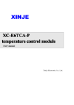
m
ModeAudible Tones
Programming Mode Audible Tones
ESC Funct
Throttle Calibration
I
Brake
Brake On
/Off
Battery type
?
NiCad
/NiMH
LiPo
3
Low Voltage Cutoff Threshold
Lorr,2.8V/50%
Medium3.0Vl60%
Hish3.2Y 165%
4
!..$gre
Factory Setup Defaults
Restore
5
Timing Setup
Automatic (7-30' )
Low (7-22" )
High(22-30"
6
VVVV
VVV VVV VVV VVV
7
)
Soft Acceleration Start Ups
Very Soft
Soft Acceleration
Start Acceleration
Governor Mode
Rpm
Heli
off
first range
Heli second range
8
9
Motor Rotation
wwww
Forward/Reverse
Switching Freque
8kHz
l6kHz
t0
Low Volt?ge CutoffType
Reduce Power
Hard Cut
Off
Using Your New ESC
Improper polarity or short circuit will damage the ESC therefore it is your
responsibility to double check all plugs for proper polarity and firm fit BEEORE
connecting the battery pack.
Alert Tones
l.TheHobbyking ESC is equipped with audible alert tones to indicate abnormal conditions
at power up.
2.
Continuous beeping tone (xt'.*<*)
minimum position.
-
Indicates that throttle stick is not
3. Single beeping tone followed by a one
second pause
(* * * *)-
in
the
Indicates
that the battery pack voltage exceeds the acceptable range. (The ESC
automatically checks and verifies the battery voltage once the battery is connected).
Built-in Intellieent ESC Safetv Functions
1. Over-heat protection: When the temperature of ESC exceed 110 deg C, the ESC
will reduce the output power to allow it too cool.
2. Lost Throttle signal protection: The ESC will automatically cut power
to the motor when it detects a lost of throttle signal for 2 second,
then motor
will emit continuous beeping tone.
Powering up the ESC for the first time
Calibration
a
The Hobbyking ESC fearures Automatic Throttle Calibration to attain the smoothest
throttle response and resolution throughout the entire throttle range of your
transmitter. This step is done once to allow the ESC to "learn and memorrze" your
Transmitter's throttle output signals and only repeated if you change your
transmitter.
l.Switch your Transmitter ON and set the throttle stick to its maximum position.
2.Connect the battery pack to the ESC. Wait for about 2 seconds, the motor will beep
for twice, then put the throttle in the minimum position, the motor will also beep, which
indicates that your ESC has got the signal range of the throttle from your transmitter.
The throttle is now culibrsted and your ESC is ready
for operation.
1.
2.
3.
Switch your Transmitter
oN
and set the thronle to its
!0ruum
l..sition.
Connect the battery pack to the ESC.
Wait untii you hear two short beeps (oo
oo
or oo) confirriii:rg
::i: ::e
ESC has
now entered the programming mode.
4'
If the throttle stick is left in the maximum position beyond 5 seconds.
the ESC will begin the sequence from one function and its associated
setting options to another. (Please refer to the table below to cross reference
the functions with the audible tones).
5'
When the desired tone for the function and setting option is reached, move
the throttle stick down to its minimum position. ESC will emit two beeps (**)
confirming the new setting has been stored.
The ESC only allows the setting of one function at a time.
6-
Therefore should you require making changes to other function, disconnect
the battery pack and wait 5 seconds to reconnect the battery and repeat
the
above steps.
1.SwitchyourTransmitteroNandsetthethrott1etoits!u@position.
2.
3'
Connect the battery pack to the ESC.
When the ESC is first powered up, it emits two sets of audible tones in
succession indicating the status of iti working status
.
* The first set of tones denotes the number
of cells in the LiPo pack connected to
the ESC. (Three beeps (***)indicates a 3 cell LiPo pack while 4 beeps
(*,x**)
indicates a4 cell LiPo pack).
* The second set denoting Brake status (one
beep(*) for Brake ..ON,, and two
beeps (**) for Brake "OFF"),
*The ESC is now ready for use.
General Safetv Precautions
'
Do not install the propeller (fixed wing) or drive pinion(helicopter) on the
motor
when you test the ESC and motor for the first time to verify the correct settings
on your radio' Only install your propeller or pinion after you have confirmed
that the settings on your radio is correct.
o
o
o
.
o
o
Never use ruptured or punctured battery cells.
Never use battery packs that are knorn'n to overheat.
Never short circuit battery or tnotor tenninals.
Always use proper insulation material for cable insulation.
Always use proper cable connetors.
Do not exceed the number of cells or
serv-os specified by the ESC.
Wrong battery polariry rviil damage the ESC and r-oid the wananty.
o
o
Install the ESC in a suitable location u-ith adequate ventilation for cooiing.
This ESC has a built-in over temperafure cutoff protection feature that vv'ill
immediately cut power to the motor once the ESC temperattire exceecls the
230 Deg F/ 110 Deg C high temperature limit.
Use only batteries that are supported by the ESC and ensure the coriect
polarity before connecting.
Switch your Transmitter ON and ensure the throttle stick is in the tninimum
o
Never switch your transmitter OFF while the battery is connected to I'our
.
position before connecting the battery pack.
ESC.
.
o
.
o
Only connect your battery pack just before flying and do nct leave your
battery pack connected after flying.
Handle your model with extreme care once the battery pack is connectecl anci
keep away from the propeller at all times. Never stand in-line or directly in
fi'ont of any rotating parts.
Do not immerse the ESC undenvater or allorv it to get wet while por,vered up.
Always fly at a designated flying site and abide by the rules and -eriidelities
set by your flying club.
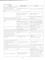
Trouble Shooting
Action
Possible Reason
Trouble
Motor doesn't work, but there are
The ESC throttle calibration has
audible tones signalling the
number of cells after Powering
uP
Set up the ESC throttle calibration
not set up.
ESC.
Motor doesn't work and no audible
tone emitted after connecting the
battery. Servos are not working
either,
Poor/loose Connection between
battery Pack and ESC,
Clean connector terminals or
replace connector,
No power
Replace with a freshlY charged
battery pack
Poor soldered connections (drY
joints)
Wrong battery cable PolaritY
throttle cable connected to
receiver in the reverse PolaritY
ESC
Faultv
Or Motor doesn't work after
powering uP the ESC' An alert
tone with single beePing tones
followed by a short Pause (x x x x)
is emitted,
Motor doesn't work after Powering
up the ESC. An alert tone with
continuous beePing tones (****)
is emitted.
Motor doesn't work after Powering
up the ESC,ESC emits two audible
tones followed bY short beePs (oo
oooooo)
Motor runs in reverse rotation
Check and verify cable PolaritY
Check the ESC cable connected to
the ESC to ensure the connectors
are in the correct polaritY.
Replace
ESC
ESC
ESC and motor
Clean connector terminals or
replace connectors
Burnt motor coils
Replace motor
Poor
Motor doesn't work and no audible
tone emitted after connecting the
battery BUT servos are working.
Re-solder the cable connections
/ loose connection betw
Poor soldered connections(drY
joints)
Re-solder the cable connection
The battery pack voltage exceeds
the acceptable range.
Replace with a freshly charged
battery pack
Check battery pack voltage
The throttle stick is not in lhe
minimum position at Porver uP,
Move the throttle stick to the
minimum position.
Reversed throttle channel caused
the ESC to enter the Programming
mode.
Enter the servo reverse menu on
your transmitter and reverse the
Note:
throttle channe!.
For Futaba radios set the throttle
channel
Wrong cables polaritY betwe
the ESC and the motor.
9
to
Reverse.
Swap any two of the three cable
connections betiveen the ESC and
the Motor or access the Motor
Rotation function via the ESC
programming mode and change
the pre-set parameters,
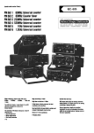
Trouble
Possible Reason
Action
Check proper operation of the
radio equipment.
Check the placement of the ESC
Lost throttle signal
Motor stops running in flight.
and the Receiver and check the
route of the receiver's aerial and
ESC cables to ensure there is
adequate separation to prevent RF
intefference.
Install a ferrite ring on the ESC's
throttle cable.
Battery Pack voltage has reached
the
Low Voltage Protection
threshold.
Possible bad cable connectio
Possible RF Interference at the
flying field.
Motor restarts abnormally
Overheats
ESC
Inadequate
Ventilation
Land the model immediately and
replace the battery pack.
Check and verify the integrity of
the cable connections
The normal operation of the ESC
may be susceptible to surrounding
RF interference, Restart the ESC
to resume normal operation on
the ground to verify recurrence, If
the problem persists, test the
operation of the ESC at a different
flying field.
Relocate the ESC to allow better
ventilation
Servos drawing too much current
and over loading the ESC.
Over sized motor or prop
10
Use servos that are adequately
the ESC. The maximum
BEC current drawn should be
within the BEC limits.
Reduce Prop size or resize the
sized for
motor