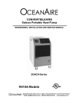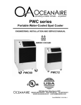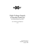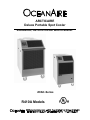
1
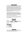
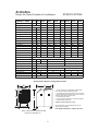
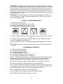
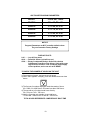
ARCTICAIRE
Deluxe Portable Spot Cooler
ENGINEERING, INSTALLATION AND SERVICE MANUAL
2OAC-Series
R410A Models
TABLE OF CONENTS
PAGE
GENERAL DESCRIPTION ….................................
1
PRODUCT DATA AND SPECIFICATIONS............
2
UNIT DESCRIPTION
Standard Features..................................
3
Applications / Operation..........................
4
Electrical..................................................
5
Use of Extension Cords...........................
6
Three Phase Monitor...............................
7
Condensate.............................................
8
Accessories………...................................
9 - 15
Installation................................................
16
Electronic Controller.................................
17-19
Replacement Parts Procedure.................
20
Troubleshooting Guide.............................
21
Preventive Maintenance...........................
22
Interior View.............................................
23
Piping Schematic......................................
24
SERVICE
DIAGRAMS
Wiring Diagrams.........................................
25 - 31
WARRANTY Statement.............................
32
FORWARD
This manual provides the user with basic details for the installation
and operation of the Oceanaire ARCTICAIRE spot cooler. It is recommended to read and fully understand the instructions outlined
within this manual, before operating the ARCTICAIRE unit.
As with all commercial air conditioning equipment, it is recommended
to have the ARCTICAIRE sized and installed by a licensed specifying
engineer and contractor, in accordance with all local and state codes.
The length of service received can be extended by following the
installation and preventive maintenance instructions.
NOTICE
In our ongoing process of continuous improvement, the items and
procedures described in this manual are subject to change without
notice. Please note model and serial number of the ARCTICAIRE
unit when contacting the factory.
GENERAL DESCRIPTION
The Oceanaire ARCTICAIRE is a portable air-cooled spot cooler
designed for permanent or temporary spot cooling or heating applications. The entire air conditioning unit has been built in an premium
sheet metal cabinet, equipped with heavy-duty casters for mobility.
All ARCTICAIRE models come with a 10-foot power cord for electrical connection and added mobility in service. These spot-coolers are
designed to direct air to specific areas or objects through a discharge
grill located on the upper-front of the unit, while rejecting heat from
the top of the unit. The ARCTICAIRE models range in cooling capacities from 12,000 BTU/HR to 60,000 BTU/HR to satisfy most
space cooling requirements.
The ARCTICAIRE is a self-contained unit with the entire cooling
system, evaporator and condenser fan motors and electrical
components neatly arranged in a gray polyester powder coated metal
cabinet. When connected to the proper source of electrical power,
the ARCTICAIRE is controlled by a solid-state electronic controller,
with numerous options of temperature and airflow controls that will
provide the desired level of comfort and cooling.
A wide variety of accessories and factory installed options are available for the ARCTICAIRE units allowing for improved performance
and added versatility.
NOMENCLATURE
2O AC 24 1 2
DELUXE
PORTABLE
VOLTAGE
AIR-COOLED
SINGLE PHASE
NOMINAL
CAPACITY
CAPACITY RATING
12..........12,000 BTU/HR
18..........18,000 BTU/HR
24..........24,00 BTU/HR
36..........36,000 BTU/HR
60……...60,000 BTU/HR
WARRANTY CARD
It is important that the warranty card be filled out completely and
returned to the factory within fourteen (14) days of installation of the
unit in order to receive the benefits of the warranty.
1
ArcticAire
SPECIFICATIONS
Deluxe Air-Cooled Portable Air Conditioners
MODEL: 2OAC 1211 1811 2412
Cooling Capacity
1
11,800
16,800
115/1
Voltage (V/Phase) at 60Hz
24,020
3612
3632
3634 6012
6032
6034
36,050
36,050
36,050
60,050
60,050
60,050
208-230/1 208-230/1 208-230/3 460/3
208-230/1 208-230/3 460/3
Cooling Amps 6
10.4
14.1
14.9
18.1
17.2
8.7
32.0
20.4
14.8
Cooling Watts 6
1180
1670
2700
3620
3620
3620
6000
6000
6000
In Rush Current (Amps)
77.5
100.5
90
140
122
122
169
140
140
Plug Type
5-15P
5-20P
6-20P
6-30P
L15-20P
L16-20P 6-50P
L15-30P
L16-20P
3
10.0
10.0
8.9
10.0
10.0
10.0
10.0
10.0
10.0
Compressor HP
1
1 1/2
2
3
3
3
5
5
5
Compressor RLA
9.5
12.3
10.5
13.6
8.8
5.0
27.6
18.1
9.0
Compressor LRA
50
63
48
83
77
35
158
137
62
Evap CFM 4
400
600
810
1310
1310
1310
1950
1950
1950
Evap Motor HP
1/8
1/8
1/3
1/3
1/3
1/3
1
1
1
Evap Motor Watts
200
210
350
375
375
375
550
550
550
Condenser CFM
580
930
1010
1390
1390
1390
2200
2200
2200
Condenser Motor HP
1/8
1/8
1/3
1
1
1
1
1
1
Condenser Motor Watts
280
450
330
460
460
460
750
750
750
EER
Condensate
5 Gallon Condensate Tank - STANDARD (Pump Optional)
Sound Level 5
54
60
R-410A Charge Oz.
18
40
(A) Height with Casters (in.) 36 1/2
65
37
20
24
(C) Depth (in.)
25
30
(D) Height w/o Casters (in.) 32 1/2
180
260
Shipping Weight (lb.)
200
285
Shipping Volume (cu. ft.)
19
80
50 1/4
52 1/4
28
35
39 1/2
Net Weight (lb.)
78
66
44 1/2
(B) Width (in.)
Pump -STANDARD (20 ft. Lift)
69
39
46
45
260
365
285
405
28
380
485
485
420
525
525
40
515
555
48
Specifications subject to change without notice
C
B
D
1. Cooling Capacity is total BTUH at 80ºDB/67ºWB
return air, 95ºF Outdoor at high fan speed
2. Time Delay fuses/circuit breakers are recommended
3. EER is determined at high fan speed, with condenser
discharge air ducted into another area
4. CFM with free discharge
5. Sound Pressure, dB at 5 feet, commercial operation
6. Amps & Watts at 208 Volts
A
Ambient operating range 65º to 105º
May operate down to 55º if equipped with hot gas
bypass (Factory installed)
50 Hz MODELS AVAILABLE - CONSULT FACTORY
Note: Condenser inlet air plenum adds
13 inches to dimension “C”
2
STANDARD FEATURES
CABINET
The ARCTICAIRE Series spot cooler has a cabinet that is constructed of 18 gauge steel
with a polyester powder coated finish that will compliment any decor. The cool blue front
compliments any surrounding space, and is insulated with sound-absorbing insulation for
cool, quiet comfort. All units come equipped with handles and premium swivel casters
for portability and convenient set-up.
DELUXE ELECTRONIC CONTROLLER
Each ARCTICAIRE unit is equipped with deluxe electronic controller. When power is
connected to the unit, the thermostat will control the unit to cool a space to the desired
temperature. The thermostat is also capable of controlling the fan to operate automatically (when needed) or continuously.
One additional feature of the Deluxe Electronic Control is that it will display a condition
alarm CON. CON displays when a condensate alarm, or a high pressure reset condition
has been met. To protect the compressor from short-cycling, there is a built-in time
delay.
FAN SPEED CONTROL
One of the features of the electronic controller is that the unit supply fan can be controlled automatically or manually. In AUTO mode, the evaporator blower will adjust air
flow automatically for added comfort and performance Or if desired, the fan speed can
be set to MANUAL mode and the evaporator blower will run continuously at one of six
levels of fan speed.
CONDENSATE RESERVOIR/PUMP
ARCTICAIRE units come equipped with a means for handling the condensate generated
during the cooling process. All models except the 2OAC60 models come equipped
with a Condensate Reservoir Tank, that captures the condensate from cooling. The tank
can then be easily removed from the unit and emptied as required.
The 2OAC60 models come equipped with an Automatic Condensate Pump that disposes of the condensate. The pump comes with a 20 foot long vinyl hose that allows for
the disposal of the condensate water to a drain. The automatic pump is capable of a
20ft lift, to handle almost any installation requirement.
FILTERS
All ARCTICAIRE units are equipped with washable filters at the air intakes. Electrostatic
mesh air filters located behind the evaporator return air grill serve to filter the air before it
is cooled, and behind the condenser return air grill to prevent dust build-up. Both filters
can be easily removed and cleaned.
HIGH PRESSURE SAFETY SWITCH
Located on the back of the ARCTICAIRE unit is a manual re-set high pressure switch,
used for the protection of the compressor. If the condensing pressure exceeds the limit
setting, the cut-out shuts down the compressor, while the evaporator fan remains running. The display will indicate CON. The compressor can be re-started, once the condensing pressure has lowered, by depressing the “RESET” button.
POWER CORDS
All ARCTICAIRE units come with power cords, convenient connection and portability. All
units except the 5-ton models, and 3-phase models are equipped with LCDI for added
safety devices.
3
APPLICATIONS
COOLING MODE—SPOT COOLER
The ARCTICAIRE can be used in an open environment to cool specific objects or "spots".
Spot Cooling is a convenient and economical way to provide air conditioning where
cooling the entire space is impractical. Cool air is discharged from the unit and is directed
where it is needed. Nozzle kits can be used to improve direction of the cooling airflow.
AREA COOLER
When the ARCTICAIRE is installed in an area that is not totally enclosed, the condenser
hot air exhaust duct directs condenser air out of the area, allowing the evaporator air to
cool the specific space.
ROOM AIR CONDITIONER
When ducted, the OceanAire ARCTICAIRE can be used as a room air conditioner to cool
an enclosed space. Using the condenser return air plenum (2DCP) and ceiling discharge
kit (CK) and ceiling panel kits CK-PL accessories, the 2OAC can operate as a room air
conditioner with the condenser air isolated form the conditioned space.
ARCTICAIRE—OPERATION / DESCRIPTION
OUTDOOR FAN DISCHARGE
“HOT”
INDOOR FAN
SUPPLY AIR
“COOL”
ELECTRONIC
CONTROLLER
CONDENSER
AIR INLET
(Back of Unit)
RETURN AIR
GRILL
AND FILTER
ARCTICAIRE OPERATION
4
SERVICE CORD
All 2OAC-Series units are equipped with the standard ten foot long service cord
with plug configurations and receptacle requirements as shown in this chart.
2OAC1211, 2OAC1811, 2OAC2412 and 2OAC3612 units come with LCDI
(Leakage Current Detection & Interruption) devices that serve as a means of
electrical protection.
CAUTION—DO NOT USE THE LCDI AS AN ON/OFF SWITCH FOR THE
UNIT
All 3-phase models are equipped with locking plugs for added connection reliability. Refer to the chart below for plug and receptacle details for all
ARCTICAIRE models.
A DAMAGED LCDI POWER SUPPLY CORD MUST
BE REPLACED WITH A NEW POWER SUPPLY
CORD AND NOT REPAIRED
UNIT/MODEL
PLUG CONFIGURATION
115 VOLT
2OAC1211
RECEPTACLE
15A-125 VOLT
NEMA 5-15P
NEMA-5-15R
20A-125 VOLT
NEMA 5-20P
NEMA 5-20R
20A-250 VOLT
NEMA 6-20P
NEMA 6-20R
30A-250 VOLT
NEMA 6-30P
NEMA 6-30R
50A-250 VOLT
NEMA 6-50P
NEMA 6-50R
208-230 VOLT 3-PHASE
2OAC3632
2OAC6032
30A-250 VOLT
NEMA L15-30P
NEMA L15-30R
460 VOLT 3-PHASE
2OAC3634
2OAC6034
20A-460 VOLT
NEMA L16-20P
NEMA L16-20R
115 VOLT
2OAC1811
208-230 VOLT SINGLE PHASE
2OAC2412
208-230 VOLT SINGLE PHASE
2OAC3612
208-230 VOLT SINGLE PHASE
2OAC6012
5
USE OF EXTENSION CORDS
CAUTION:
FOR MODEL 2OAC1211 AN EXTENSION CORD CAN BE USED PROVIDED IT IS
RATED AT LEAST 15 AMPS @ 115 VOLTS WITH GROUNDING-TYPE ATTACHMENT PLUG AND GROUNDING TYPE CONNECTOR (LOAD FITTING)
FOR MODEL 2OAC1811 AN EXTENSION CORD CAN BE USED PROVIDED IT IS
RATED AT LEAST 20 AMPS @ 115 VOLTS WITH GROUNDING-TYPE ATTACHMENT PLUG AND GROUNDING TYPE CONNECTOR (LOAD FITTING)
FOR MODEL 2OAC2412 AN EXTENSION CORD CAN BE USED PROVIDED IT IS
RATED AT LEAST 20 AMPS @ 250 VOLTS WITH GROUNDING-TYPE ATTACHMENT PLUG AND GROUNDING TYPE CONNECTOR (LOAD FITTING)
FOR MODEL 2OAC3612 AN EXTENSION CORD CAN BE USED PROVIDED IT IS
RATED AT LEAST 30 AMPS @ 250 VOLTS WITH GROUNDING-TYPE ATTACHMENT PLUG AND GROUNDING TYPE CONNECTOR (LOAD FITTING)
FOR MODEL 2OAC6012 AN EXTENSION CORD CAN BE USED PROVIDED IT IS
RATED AT LEAST 50 AMPS @ 250 VOLTS WITH GROUNDING-TYPE ATTACHMENT PLUG AND GROUNDING TYPE CONNECTOR (LOAD FITTING)
FOR MODELS 2OAC3632 AND 2OAC6032 AN EXTENSION CORD MAY BEUSED
PROVIDED IT IS RATED AT LEAST 30 AMPS @ 250 VOLTS, 3 PHASE
FOR MODELS 2OAC3634 AND 2OAC6034 AN EXTENSION CORD CAN BE USED
PROVIDED IT IS RATED AT LEAST 20 AMPS @ 600 VOLTS, 3 PHASE
SPECIAL NOTICE—THREE PHASE OPERATION
Models 2OAC3632, 2OAC3634, 2OAC6032 and 2OAC6034
All three-phase ARCTICAIRE models are equipped with a threephase monitor for added compressor protection. The phase monitor,
located in the control box, has multi-color LED that reports status.
The monitor protects the compressor from reverse operation, phase
loss and low voltage situations. Further description of the threephase monitor is located in the electrical section of the manual.
NOTICE - DO NOT OPERATE ANY THREE-PHASE UNIT BY BYPASSING THE MONITOR, THIS WILL VOID THE WARRANTY
6
Three Phase Monitor
Three-Phase units can be equipped with monitors for motor protection.
The Oceanaire Three-phase Monitor safeguards the unit against
incorrect compressor rotation, low-voltage and/or loss of power in any
one of the power legs. The monitor is installed in the control box and is
equipped with an LED for diagnosis of an improper electrical condition
(see diagrams below). When power is connected, the thermostat WILL
NOT power up, until the monitor start delay has been timed out. If the
thermostat does not power up, an electrical condition may need to be
addressed. Remove the control box cover and check the observe the
LED on the phase monitor. The LED signals the following:
GREEN-BLINKING - Start delay, 120 sec.
GREEN - Proper Operation
RED/GREEN-BLINKING signals reverse phase rotation. Switch any
two of the power leads for the unit, NOT THE MONITOR LEADS, and
re-start.
RED-BLINKING signals improper voltage and/or phase loss. Correct
the power problem, then re-start the unit.
In the event of a power interruption, the unit will re-set to a start-up
condition. The Phase Monitor will not allow the unit to start until power
is corrected.
LED
NOTICE
UNIT IS EQUIPPED WITH 3-PHASE POWER
MONITOR (WITH LED)
LED INDICATION
GREEN (BLINKING) = START DELAY
GREEN = PROPER OPERATION
RED/GREEN/BLINKING = PHASE REVERSAL
RED (BLINKING) = IMPROPER LEG VOLTAGE
OR PHASE LOSS
START DELAY = 120 SECONDS
7
CONDENSATE RESERVOIR TANK
For Models 2OAC12, -18, -24 -36, a 5-gallon polyethylene tank is provided standard, to
collect condensate. The tank is located in the lower, front section of the unit. A high
water level cut-out switch is used to stop the compressor and condenser fan automatically
when the tank's pre-set water level has been reached. The evaporator fan will continue to
run, circulating air. The control display will read “CON”
Condensate Tank
For 2OAC12, 2OAC18, 2OAC24 and
2OAC36, condensate water drops
from drain pan into trough on tank
*Tank Water Level
Adjusting Screw
Spring
Max Water
Level
4" From Top
Handle
High Water Level
Cut-Out Switch
Condensate
Tank Tray
TANK LEVEL ADJUSTMENT INSTRUCTIONS
An adjustment screw is provided to vary the cut-off of the tank full switch. If a lighter (less
weight) level of water is desired, turn the adjusting screw clockwise. Do not exceed 6 full
turns counter-clockwise.
CAUTION, TURN UNIT OFF: BEFORE ADJUSTING SET SCREW
BEFORE REMOVING TANK TO EMPTY CONDENSATE
Turn screw clockwise to lower water level. Less water makes tank lighter and easier to
remove.
NOTE: Max. and Min. water levels shown are those at which the unit will shutdown and
not restart until the condensate tank has been drained.
8
ACCESSORIES
CK-12
CK-16
CK-12PL
(2 Req’d for
2DCP-4
2DDA-6
2DDA-10
2DDA-16
2NK-1
2NK-2
2NK-3
DEP-10
2DEP-12
DEP-16
2DCP-1
2DCP-2
2DCP-4
2OAC UNIT
9
2OAC – ARCTICAIRE ACCESSORIES
NOZZLE KIT
2NK-1
(2 X 4-Inch)
2NK-2
(2 X 6-Inch)
2NK-3
(2 X 8-Inch)
2OAC12
2OAC18, 24
2OAC36, 60
EVAPORATOR RETURN AIR PLENUM
DEP-10 (10-Inch Round)
2OAC12
2DEP-12 (12-Inch Round)
2OAC18, 24
DEP-16 (16-Inch Round)
2OAC36, 60
DISCHARGE DUCT ADAPTER
2DDA-6
(6-Inch Round)
2DDA-10
(10-Inch Round)
DDA-16
(16-Inch Round)
2OAC12
2OAC18, 24
2OAC36, 60
CONDENSATE PUMP KIT *
2DPC-1
115V Models
2DPC-2
230V Models
* Not Required for 2OAC60’s
CEILING PANEL KIT
CK-12
2OAC12, 18, 24
CK-16
2OAC36, 60
CK-12PL
CK-12 without Duct Flange
CKP-12
2 X 2 Ceiling Panel w/12-Inch Dia. Flange
CKP-16
2 X 2 Ceiling Panel w/16-Inch Dia. Flange
DUCT FLANGE
DF-12
DF-16
12-Inch Duct Flange
16-Inch Duct Flange
CONDENSER RETURN AIR PLENUM
2DPC-1
2OAC12
2DCP-2
2OAC18, 24
2DCP-4
2OAC36, 60
10
ACCESSORIES
2 x 2 CEILING
DUCT-PANEL
CEILING PANEL DUCT KIT, CK-12, CK-16
A ceiling panel kit is available for discharging the
condenser air above a drop ceiling.. The ceiling
panel duct kits are furnished with a white vinyl
coated flexible duct that allows for convenient
installation. A 2ft X 2ft ceiling duct- panel is
included to replace a 2ft X 2ft drop-ceiling panel
where the connection is desired.
VINYL COATED
FABRIC DUCT
DUCT STRAP
The CK-12 is available for the 2OAC12, -18 and
-24 models. The ceiling panel kit consists of
flexible duct, a 2' X 2' lay in ceiling panel and a
12-inch duct flange that attaches to the
condenser air discharge opening on the top of
the unit. The CK-16 is available for the 2OAC36
and -60models, and consists of a ceiling ductpanel, and a 16-inch flexible duct.
DUCT FLANGE
Note—Drop ceiling spaces should be vented
or large enough to handle the warm
condenser air. Check local codes to assure
compliance.
If longer runs of duct are required, table below
lists maximum duct run with no 90° elbows. For
every 90° elbow, subtract 6 feet from the run.
Ceiling
Kit
Model
Flexible
Duct
Diameter X
Length
CK-12
12 inch X
8 feet
CK-16
16 Inch X
8 feet
Fits
2OAC12
No
Fits
2OAC18
Fits
2OAC24
No
No
Fits
2OAC36
Fits
2OAC60
No
No
Maximum Equivalent
Feet (approx)
25
50
50
50
100
(ESP)
(.20)
(.25)
(.25)
(.25)
(.50)
DUCT FLANGE (DF-12, DF-16)
The optional duct flange allows for round flexible ducting to
be attached to the ARCTICAIRE condenser discharge. DF
-12 (12-inch diameter) fits all size 12, 18 and 24 units. The
DF-16 (16 inch diameter) fits all size 36 and 60 units.
NOTE: 2OAC36 and 2OAC60 units come with duct
flanges installed.
11
DUCT FLANGE
ACCESSORIES
DISCHARGE AIR NOZZLE KIT ASSEMBLY (2NK)
The optional discharge nozzle kits are used to direct the conditioned air to a specific target area. By concentrating the airflow,
the nozzles increase the air velocity towards production lines to
cool personnel or equipment. In server rooms, the nozzles can be
used to induce airflow through the rack to remove the hot air from
the area of the equipment.
2NK-1 for model 2OAC12, with (2) 4-inch diameter nozzles with
an approximate compressed length of 15 inches. The approximate
extended length is 21 inches.
2NK-2 for models 2OAC18 and 2OAC24 with (2) 6-inch diameter
nozzles with an approximate compressed length of 22 inches. The
approximate extended length is 32 inches.
Nozzle Kits
2NK-3 for 2OAC36 and 2OAC60, with (2) 8-inch diameter nozzles with an approximate compressed length of 20 inches. The
extended length is approximately 29 inches.
The nozzle kits come pre-assembles with the nozzles secured to a
mounting plate, and with edge guards. By removing the
ARCTICAIRE discharge grill, one can insert the nozzle kit into the
opening without the use of tools.
CONDENSATE PUMP KIT: 2DPC-1 and 2DPC-2
A plug-in condensate pump kit is available for applications where emptying the 5 gallon
condensate tank is not desired. The pump kit consists of a condensate pump with mounting hardware and electrical connections, along with the tubing required for the drain and
discharge of the condensate water.
The condensate pump provides for the
automatic removal of condensate water
during the cooling process. The pump is
capable of pumping against a 20 foot head,
allowing for the routing of the drain line
above the drop-ceiling to a nearby drain.
The pump is controlled by an internal floatswitch which turns the pump on and off
automatically. The pump is also equipped
with a condensate over-flow safety switch,
that will shut down the ARCTICAIRE compressor when the pump is not working prop-
Pump Kit
PARTS LIST
(1) Condensate Pump with mounting hardware
(1) 3/8-inch drain hose, 25 ft
(2) Mounting screws
(1) Drain hose — black corrugated
(2) Hose clamps
12
Kit
2DPC-1
2DPC-2
Voltage
115V
208-230V
ACCESSORIES
CONDENSER RETURN AIR PLENUM, 2DCP
Condenser return air plenums are available for installations where it is required to duct air
to the inlet of the condenser. The plenum easily attaches with one screw to the back of
the unit, and is provided with flange(s) for connecting 12-inch flexible ducting. A condenser return air plenums can substantially reduce air noise and allows the unit to operate without drawing condenser air from the conditioned space. Refer to the table below
for configuration and application information.
NOTE — When installing the condenser return air plenum with the ceiling panel
kits, allow for a minimum separation distance of 2 feet between the unit discharge
duct and the return air duct(s). It is also recommended to direct the condenser
discharge air away from the condenser return air ducts.
2DCP-1 and 2DCP-2
2DCP-4
To estimate the “equivalent feet” of condenser duct, add the length of the
condenser intake duct run and the length of the condenser discharge duct run,
and add 6 equivalent feet per bend in the duct. Make sure that you do not exceed
the rated E.S.P. to avoid shut down due to the high pressure cut-out
Plenum
Kit
Duct
Flange
2DCP-1
12-inch
2DCP-2
12-inch
2DCP-4
(2) 12-Inch
Maximum Approximate
Equivalent Feet
Estimated External
Static Pressure
2OAC12
2OAC18
2OAC24
2OAC36
2OAC60
25
50
50
50
100
(.20)
(.25)
(.25)
(.25)
(.50)
13
ACCESSORIES
EVAPORATOR RETURN AIR PLENUM, 2DEP
Evaporator return air plenums are available for installations where it is required to duct air
to the inlet of the evaporator. The evaporator return air plenums allow the user to connect
round duct (flexible or rigid) to the return air intake to reduce air noise and increase the
number of options for solving difficult cooling problems. The plenum attaches to the front
of the unit, replacing the return air grill. Refer to the table below for configuration and
application information
DEP-10 for 2OAC12 transitions the return air opening to 10-inch round duct.
2DEP-12 for 2OAC18 & 2OAC24 transitions the return opening to a 12-inch round duct.
DEP-16 for 2OAC36 and 2OAC60 transitions the return opening to a16-inch round duct.
NOTE—When a evaporator return air plenum is installed, it is recommended to set
the evaporator blower speed to high, to avoid evaporator freeze-up.
FILTER(S)
2DEP—EVAPORATOR
RETURN AIR PLENUM
Plenum Kit
Duct/Flange
2OAC12
2OAC18
2OAC24
2OAC36
2OAC60
FILTERS
DEP-10
10 inch
(1) 10”X20”X1”
2DEP-12
12 inch
(1) 15”X25”X1”
DEP-16
16 inch
(1) 12”X30”X1”
(1)15”X30”X1”
Maximum
Equivalent
Feet
25
50
50
50
100
Est. External
Static
Pressure
(.20)
(.25)
(.25)
(.25)
(.50)
14
ACCESSORIES
Discharge Duct Adapter, 2DDA
Discharge duct adapters are available for applications where ducted evaporator discharge
is required. The adapters can be easily installed on the unit without fasteners, and be
installed for either vertical or horizontal ducting. The standard discharge grille is removed
and the 2DDA is attached in the grill opening.
2DDA-6 for 2OAC12, converts the evaporator discharge to a 6-inch diameter round duct.
2DDA-10 for 2OAC18 and 2OAC24, converts the evaporator to a 10-inch
diameter round duct.
2DDA-16 for 2OAC36 and 2OAC60, converts the evaporator discharge to a 16-inch
diameter round duct.
When used in conjunction with the evaporator return air plenum, DEP, the unit can provide closed-loop cooling to and from a given space without the influence of any outside
air.
Adapter
Model
Round
Duct
Size
2DDA-6
6-inch
2DDA-10
10-inch
2DDA-16
16-inch
2OAC12
2OAC18
2OAC24
2OAC36
2OAC60
Maximum
Approx
Equivalent Feet
25
50
50
50
100
Maximum
E.S.P
.15
.25
.25
.25
.50
15
INSTALLATION INSTRUCTIONS
RECEIVING—INSPECTION:
Upon receiving your ARCTICAIRE unit, inspect the packaging for any
damage. All units are shipped on a skid, and packaged in a triple-wall
carton for added protection. In shipment, some wear may occur on the
packaging. If the packaging is heavily damaged or broken, file a claim
with the freight company immediately. Carefully unpack the unit and
remove all wrapping materials. Save all documentation and fill out the
Warranty Card and mail it to Oceanaire.
BEFORE INSTALLING
Check the air conditioner/spot cooler for any damage. All Oceanaire
products are thoroughly inspected at the factory and carefully
packaged. If any damage is evident, file a claim with the delivering
carrier immediately.
ELECTRICAL REQUIREMENTS
Check the nameplate located on the back of the unit to make certain
that the proper power is available for the unit. Refer to "Specifications"
section for voltage and amperage requirements. For proper NEMA
receptacles, refer to "Electrical service plug configuration". When using
extension cords, use the properly sized cord, and check cord voltage to
the unit.
TIME DELAY FUSES/CIRCUIT BREAKERS ARE RECOMMENDED
WARNING—OPERATING THE UNIT ON
IMPROPER VOLTAGE WILL VOID THE
WARRANTY
ACCESSORIES
Verify that all accessories are correct for the model, and that they
installed in accordance with all instructions.
START-UP
Install the unit in accordance with all local and state building codes, and
install all accessories. Allow for a clearance around the unit for future
maintenance and/or service. Level unit and lock casters, when
available. Connect power and test the LCDI on the power cord (if
available). Power up unit, via thermostat and check for proper
operation. Refer to Thermostat Operation for more details.
16
Deluxe Electronic Controller
The ARCTICAIRE controller is equipped with many features for a
more precise level of cooling and operation. Additionally, the controller can be removed from the unit and installed for remote operation, if
desired—accessory parts may be required.
OCEANAIRE
OCEANAIRE DELUXE ELECTRONIC CONTROLLER
When power is connected, the controller will display “888” momentarily, and will then go
blank. Press the POWER button, then press the TEMP SELECT button until the SET
POINT is displayed. Adjust the SET POINT to the desired temperature, and the unit will
heat/cool as required.
The systems controls temperature within +/- 2°
POWER—Turns the unit on/off when power is supplied
MODE - Selects the mode of operation from AUTO to Moisture Control.
COOL - The system will operate in cooling mode, only.
MOISTURE CONTROL - The system operates in the cooling mode to reduce humidity
within the conditioned space.
Every 4 hours, the fan is started, circulating the air, and the air temperature is recorded by
the controller. The cooling cycle is started for one hour, or until the room temperature
drops 2°, which ever comes first. This cycle repeats every four hours.
17
FAN SPEED—The operator can select between AUTO and MANUAL fan speed control.
Pressing the FAN SPEED button, will switch speed from AUTO to MANUAL. In MANUAL
mode, pressing the FAN SPEED button will change fan speed from low to high. In AUTO
the fan speed is controlled automatically. In cooling mode, the controller automatically
adjusts the fan speed to high, and as the inside temperature approaches the set point, the
fan speed will reduce. In heat mode, the fan speed goes from low to high as the temperature approaches the set point
TEMP SELECT—Allows the operator to view the controller temperatures; INSIDE = return air temperature, OUTSIDE = supply air temperature, SET POINT can be seen and
adjusted, by pressing ▲ or▼.
CONTROLLER PROGRAMMING MENU
1)
2)
3)
4)
Make sure the unit has power.
Pushing the POWER button, turn the unit “OFF”.
Press the following buttons in sequence “S-U-D-S”:
The display will begin flashing P1 and a number.
If there is no display, repeat the sequence, making sure the unit has power, but is turned
OFF.
5) To adjust any program parameter, press the ARROW UP▲ or ARROW DOWN ▼
button until the desired value is displayed.
6) Use the “MODE” button to scroll through the programmable parameters P1 through
P16.
7) If no buttons are pushed, the display will then return to the “OFF” position after about
50 seconds.
PROGRAMMING PARAMETERS
P1—High Fan Speed Limit Setting
P2—Low Fan Speed Limit Setting
P4—Temperature Sensor Calibration
P10— Temperature Display, °F or °C
P13—Supply Fan Operation, Cycling or Continuous
P15—Fan Motor Type Setting, PSC or Shaded Pole
P1, P2 - To adjust fan speed settings, P1 represents the high fan speed parameter, while
P2 represents the low fan speed parameter. When using nozzle kits, discharge duct
adapters and evaporator plenums, setting P1 to 85 will help to avoid freeze ups.
P4 - Adjust the P4 setting to match the actual INSIDE room temperature, if needed.
P10 - Use this parameter to display temperatures in the desired units.
P13 - To cycle the evaporator fan with the compressor, access code P-13. Press the up
or down button to switch to “CYC”, which means cycle the fan with the compressor. The
factory default setting is “CON”, which means continuous fan operation.
P15 - Fan Motors are PSC type, SC - should be selected.
8) Press POWER—you should see a code A (followed by numbers)
Press POWER and the unit will start at the new settings
18
ARCTICAIRE PROGRAM PARAMETERS
MODEL
CODE SETTINGS
2OAC12
P1 = 85, P2 = 35
2OAC18
P1 = 80, P2 = 50
2OAC24
P1 = 70, P2 = 50
2OAC36
P1 = 85, P2 = 40
2OAC60
P1 = 85, P2 = 45
NOTICE
Program Parameters are NOT controller default values.
They are Oceanaire Factory Settings
DISPLAY FAULTS
LAC……. Low AC line power
AAA……. Failed Air Sensor (unit will not run)
CON…….Empty Condensate Bucket—Units with a bucket
Condensate Pump Over-Flow Alarm—Units with pump
High Pressure Cut-Out—Low condenser water supply
correct problem, and re-set unit at HP RESET
TO CHECK THE NUMBER OF HOURS ON THE UNIT
1) Disconnect unit power, and reconnect unit power.
2) When “888” appears in display, push and release the arrow down
button
3) The first set of numbers displayed reads thousands of hours:
02 = 2000, 04 = 4000 hours, 00 means less than 1000 hours.
4) The second set of numbers read hours directly:
58 = 58 hours. 742 = 742 hours.
6) Add the 2 number sets together to get total hours.
03 and 486 = 3486 hours. 01 and 59 = 1059 hours.
TOTAL HOURS REPRESENTS COMPRESSOR “RUN” TIME
19
REPLACEMENT PROCEDURE FOR PARTS
IT IS RECOMMENDED THAT ALL OCEANAIRE UNITS BE SERVICED BY A
LICENSED TECHNICIAN
WARNING—TO AVOID INJURY, DISCONNECT UNIT POWER PRIOR TO SERVICING
A. FAN MOTORS
1. Remove cabinet's left-side panel (when looking at the front of the unit).
2. Evaporator fan motor—disconnect evaporator motor wires from evaporator fan
contactor and fan speed rocker switch. Condenser fan motor—disconnect condenser
motor wires from condenser fan contactor.
3. For all model sizes 12, 18 and 36, remove the screws securing motors and inletring to blower housings (all screws are external and visible), and remove blower wheelmotor assembly. Remove the blower wheel set screw and disassemble the blower
wheel from the motor shaft and remove the motor.
For models size 60—loosen blower wheel shaft set screw, and remove the screws
securing the motor mount to the blower housing and remove motor and mount.
Remove the motor from the motor mount.
4. Install the new motor, reversing the removal procedure.
B. ELECTRONIC CONTROLLER (2 PARTS)
1. To remove the Heat/Cool display, remove the cabinet's left-side panel (from front).
Locate the two nuts securing the display to the front panel. Unplug the display cable
and remove display. Install new display and secure. Plug in display cable.
2. To remove the Power Module, remove the rear control box cover. Disconnect wires,
and remove power module. Install new power module, and re-wire in accordance with
the wiring diagram.
5. CONDENSATE PUMP (ON ALL 5-TON UNITS OR ON UNITS WHERE THE
CONDENSATE PUMP KIT HAS BEEN INSTALLED)
1. Remove side panel.
2. Remove brackets securing condensate pump in base pan, or condensate tank tray pan
3. Disconnect pump wire leads at Molex connectors. Remove retainer clamp and tubing.
4. Replace pump, install by reversing procedure.
E. HIGH PRESSURE SAFETY SWITCH
1. Remove cabinets right side panel, or right rear side panel of Model 60.
2. Remove flare nut that secures capillary to the refrigeration system high pressure side.
A Schrader valve is located in the discharge port, and allows removal without dumping
the refrigerant charge.
3. Remove two screws that retain high pressure switch.
4. Disconnect wire leads from compressor contactor and condensate pump safety switch.
5. Install new High Pressure Control, reversing the procedure.
To gain access to compressor and compressor run capacitor, remove left hand side
panel.
20
TROUBLESHOOTING GUIDE
The following steps and procedures are recommended for correcting the problems
indicated. In the event that the problem can not be corrected, service may be required.
SERVICE SHOULD BE PERFORMED BY A QUALIFIED AIR CONDITIONING
SERVICE TECHNICIAN
PROBLEM: UNIT DOES NOT POWER UP
CAUSE: Power interruption
REMEDY: Check LCDI (on models with LCDI), and reset LCDI. Check external power
supply making sure that the disconnect is ON. Check for blown fuses or tripped circuit
breakers. Reset or replace if needed.
CAUSE: Loose display cable
REMEDY: Re-seat display cable at display and power module.
CAUSE: Phase Monitor Fault (3-Phase Models)
REMEDY: Check Phase Monitor, and correct power problem>
PROBLEM: EVAPORATOR FAN RUNS BUT COMPRESSOR AND CONDENSER
FAN DO NOT START
CAUSE: SET POINT — setting may be too high for cooling or too low for heating.
REMEDY: Make sure set-point is adjusted accordingly. You should see a red dot to
the right of the temperature display indicating compressor ON.
Note—there is a time delay for the compressor
CAUSE: Loose Display Cable
REMEDY: Examine the control unit for loose wires. Tighten any loose connections.
CAUSE: Condition Alarm—”CON”.
REMEDY: Check condensate tank and empty tank or check condensate pump and
make sure pump is working properly and that there is no kink in the drain line from the
pump.
CAUSE: High Pressure Cut-Out—”CON” Check High Pressure Cut-out Switch.
Press Reset and clear away any obstructions to the condenser intake or condenser
discharge.
CAUSE: Compressor contactor open or burned.
REMEDY: Replace contactor
CAUSE: Defective Power Module
REMEDY: Replace Power Module.
21
PREVENTIVE MAINTENANCE
ARCTICAIRE Spot Coolers are designed to last a long time and to
give maximum performance and reliability with minimum maintenance. To prolong the life of the unit, regular maintenance must be
performed as specified below:
BLOWER MOTORS
The motors on all units have permanently lubricated bearings. No
oiling is necessary
FILTERS
A clogged filter will cause the unit to operate at greatly reduced
efficiencies. We recommend that the filter be inspected on a regular
bases every six weeks or more often depending on the environment.
The evaporator filter is located behind the return air grille and can be
easily removed and cleaned. The condenser filter is located in the
lower backside of the unit. Remove by loosening one screw holding
retaining clip and pull out. The filters must be washed periodically as
needed by placing them in a dishwasher or soaking them in a
solution of warm water and detergent for 10 minutes. Then rinsing
them clean with hot water and shaking excess moisture from filter.
CONDENSATE PUMP
Condensate pumps come standard on all Size 60 models, and may
be installed as options on size 12, 18, 24 and 36 models. When
servicing pump follow these steps;
1. Make certain that the unit is disconnected from the power source
before attempting to service or remove any component.
2. Be sure the floats move freely. Clean as necessary.
3. Remove the volute and check for obstructions. Clean as needed.
4. Clean the tank with warm water and mild soap when mineral
deposits are visible.
5. Check the inlet and outlet piping. Clean as necessary. Be sure
there are no kinks in the lines that would inhibit flow.
GENERAL
When necessary maintenance steps outlined above are followed, the
air conditioner will provide long and reliable service. The refrigeration
and electrical circuits of the system should only be serviced by a fully
qualified service technician.
22
Outdoor
Blower/Motor
Filter/Drier
Indoor
Blower/Motor
Cooling-Only
Display
Evapotator
Coil
Condenser
Coil
Display
Cable
Control
Box
Condensate
Tank
2OAC12
INTERIOR VIEW
23
SUCTION LINE
EVAPORATOR
BLOWER
AIR
EVAPOTATOR
COIL
CAPILLARY
TUBES
CONDENSER
BLOWER
HP RESET
CONDENSER
COIL
ACCESS
VALVES
FILTER/
DRIER
DISCHARGE LINE
COMPRESSOR
REFRIGERANT FLOW
PIPING SCHEMATIC
Air-Cooled Spot Cooler
24
AIR
CONDENSATE
TANK FULL
SWITCH
COM
NO
OCEANAIRE
NC
POWER MODULE
OPTIONAL CONDENSATE PUMP
2DPC-1 (115V) OR 2DPC-2 (208-230V)
INSTALL SAFETY SWITCH IN LOW-VOLTAGE
LOOP REPLACING TANK FULL SWITCH
AIR-COOLED SPOT COOLER
MODELS 2OAC1211, 2OAC1811
115 V / SINGLE-PHASE
MODELS 2OAC2412
208-230 V / SINGLE-PHASE
25
CONDENSATE
TANK FULL
SWITCH
COM
NO
OCEANAIRE
NC
POWER MODULE
Plug 6-30P
OPTIONAL CONDENSATE PUMP KIT
2DPC-2 (208-230V)
INSTALL SAFETY SWITCH IN LOW-VOLTAGE
LOOP REPLACING CONDENSATE TANK FULL
AIR-COOLED SPOT COOLER
MODELS 2OAC3612
208-230 V/ SINGLE-PHASE
26
CONDENSATE
TANK FULL
SWITCH
COM
NO
OCEANAIRE
NC
POWER MODULE
Plug L15-30P
OPTIONAL CONDENSATE PUMP
2DPC-2 (208-230V)
INSTALL SAFETY SWITCH IN LOW-VOLTAGE
LOOP REPLACING TANK FULL SWITCH
AIR-COOLED SPOT COOLER
MODELS 2OAC3632
208-230 V / 3-PHASE
27
CONDENSATE
TANK FULL
SWITCH
COM
NO
OCEANAIRE
NC
POWER MODULE
Plug L16-20P
OPTIONAL CONDENSATE PUMP
AIR-COOLED SPOT COOLER
MODELS 2OAC3634
460 V / 3-PHASE
2DPC-2 (208-230V)
INSTALL SAFETY SWITCH IN LOW-VOLTAGE
LOOP REPLACING TANK FULL SWITCH
28
OCEANAIRE
POWER MODULE
AIR-COOLED SPOT COOLER
MODELS 2OAC6012
208-230 VOLT/ SINGLE-PHASE
Plug 6-50P
29
OCEANAIRE
POWER MODULE
Plug L15-30P
AIR-COOLED SPOT COOLER
MODEL 2OAC6032
208-230 V / 3-PHASE
30
OCEANAIRE
POWER MODULE
Plug L16-20P
AIR-COOLED SPOT COOLER
MODELS 2OAC6034
460 V / 3-PHASE
31
MANUFACTURER’S LIMITED WARRANTY
The Manufacturer (OceanAire, Inc.) warrants to the original owner that the Product will be
free from defects in material or workmanship for a period not to exceed one (1) year from
date of installation. If upon examination by the Manufacturer the Product is shown to have
a defect in material or workmanship, during the warranty period, the manufacturer will
repair or replace, at its option, that part of the Product which is shown to be defective.
The Manufacturer further warrants that the product's compressor-motor will be free from
defects in materials and workmanship for five (5) years from the date of installation. If
upon examination by the Manufacturer, the Compressor-Motor is shown to have a defect
in materials or workmanship during the warranty period, the Manufacturer will repair or
replace, at its option, that compressor which is shown to be defective. Electrical parts
(such as relays, overloads, capacitors, etc.) and the sealed refrigeration system
(condenser and evaporator) are included in the one year limited warranty, but not with the
five year limited warranty of the compressor. This limited warranty does not apply:
a) if the Product has been subjected to misuse or neglect, has been accidentally or
intentionally damaged, has not been installed, maintained or operated in accordance with
the furnished written instructions, or has been altered or modified in any way.
b) to any expenses, including labor or material, incurred during removal or reinstallation of
the Product.
c) to any workmanship of the installer of the Product.This limited warranty is conditional
upon:
(i) shipment, to the Manufacturer, of that part of the Product thought to be defective.
Goods can only be returned with prior written approval from the Manufacturer. All returns
must be freight prepaid.
(ii) determination, in the reasonable opinion of the Manufacturer that there exists a defect
in material or workmanship.
Repair or replacement of any part under this Limited Warranty shall not extend the
duration of the warranty with respect to such repaired or replaced part beyond the stated
warranty period.
THIS LIMITED WARRANTY IS IN LIEU OF ALL OTHER WARRANTIES, EITHER
EXPRESS OR IMPLIED, AND ALL SUCH OTHER WARRANTIES, INCLUDING
WITHOUT LIMITATION IMPLIED WARRANTIES OF MERCHANTABILITY OR FITNESS
FOR A PARTICULAR PURPOSE, ARE HEREBY DISCLAIMED AND EXCLUDED
FROM THIS LIMITED WARRANTY. IN NO EVENT SHALL THE MANUFACTURER BE
LIABLE IN ANY WAY FOR ANY CONSEQUENTIAL, SPECIAL, OR INCIDENTAL
DAMAGES OF ANY NATURE WHATSOEVER, OR FOR ANY AMOUNTS IN EXCESS
OF THE SELLING PRICE OF THE PRODUCT OR ANY PARTS THEREOF FOUND TO
BE DEFECTIVE. THIS LIMITED WARRANTY GIVES THE ORIGINAL OWNER OF THE
PRODUCT SPECIFIC LEGAL RIGHTS. YOU MAY ALSO HAVE OTHER RIGHTS
WHICH MAY VARY BY EACH JURISDICTION.
32
USEFUL INFORMATION
MODEL:
SERIAL NUMBER:
DATE PURCHASED:
INSTALLED BY:
DATE INSTALLED:
For Technical Support, or to locate a distributor for service parts, contact Oceanaire at (847) 583-0311. Please
indicate the Model Number and Serial Number of the
unit to assure proper information and service parts.