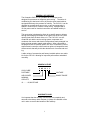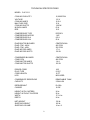
1
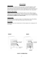
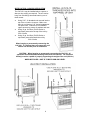
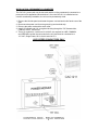
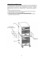
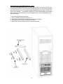
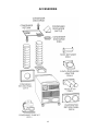
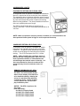
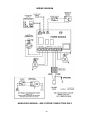
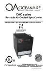
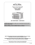
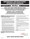
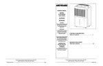
CAC series
Cool Cube
Portable Air-Cooled Spot Cooler
ENGINEERING, INSTALLATION AND SERVICE MANUAL
Form EISM-CAC, 110114 Rev 1
TABLE OF CONENTS
PAGE
GENERAL DESCRIPTION ….................................
1
PRODUCT DATA AND SPECIFICATIONS............
2
UNIT DESCRIPTION
Standard Features..................................
3
Applications / Operation..........................
4
Electrical..................................................
5
Condensate.............................................
6
Installation................................................
7
Installation—Hanging Applications………
8
Installation—Permanently Connected…..
9
Stacking Kit…………………………………
10
Accessories………………………………..
11-13
Deluxe Controller.................................
14-15
Troubleshooting Guide.............................
16
Replacement Parts Procedure.................
17
Preventive Maintenance...........................
18
Piping Schematic......................................
19
Wiring Diagram.........................................
20
SERVICE
FORWARD
This manual provides the user with basic details for the installation
and operation of the Oceanaire CAC1211 spot cooler. It is recommended to read and fully understand the instructions outlined within
this manual, before operating the unit.
As with all commercial air conditioning equipment, it is recommended
to have the CAC1211 sized and installed by a licensed specifying
engineer and contractor, in accordance with all local and state codes.
The length of service received can be extended by following the
installation and preventive maintenance instructions.
NOTICE
In our ongoing process of continuous improvement, the items and
procedures described in this manual are subject to change without
notice. Please note model and serial number of the CAC1211 when
contacting the factory.
GENERAL DESCRIPTION
The Oceanaire CAC1211 is a portable air-cooled spot cooler
designed for permanent or temporary spot cooling. The entire air
conditioning unit has been built in an premium sheet metal cabinet,
equipped with heavy-duty casters for mobility. The CAC1211 can be
operated as a stand-alone spot cooler, or can be permanently installed in a server rack, or above a drop ceiling. Equipped with a
10-foot power cord for electrical connection and added mobility in
service.
This spot-cooler is designed to direct air to specific areas or objects
through a discharge grill located on the upper-front of the unit, while
rejecting heat from the back of the unit. The CAC1211 is a selfcontained unit with the entire cooling system, evaporator and
condenser fan motors and electrical components neatly arranged in a
black polyester powder coated metal cabinet. When connected to
the proper source of electrical power, the unit is controlled by a solidstate electronic controller, with numerous options of temperature and
airflow controls that will provide the desired level of comfort and cooling.
A wide variety of accessories and factory installed options are available for the CAC1211 allowing for improved performance and added
versatility.
NOMENCLATURE
C AC 12 1 1
COOL CUBE
PORTABLE
VOLTAGE
AIR-COOLED
SINGLE PHASE
NOMINAL
CAPACITY
12..........12,000 BTU/HR
WARRANTY CARD
It is important that the warranty card be filled out completely and
returned to the factory within fourteen (14) days of installation of the
unit in order to receive the benefits of the warranty.
1
TECHNICAL SPECIFICATIONS
MODEL: CAC1211
COOLING CAPACITY
VOLTAGE
COOLING AMPS
MAX FUSE SIZE
COOLING WATTS
IN RUSH AMPS
EER
12,000 BTUH
115 V
12.0 A
15 A
1180 W
63 A
10.0
COMPRESSOR
COMPRESSOR
COMPRESSOR
COMPRESSOR
ROTARY
1 HP
9.5 A
50 A
TYPE
MOTOR
RLA
LRA
EVAPORATOR BLOWER
EVAP CFM - HIGH
EVAP CFM - LOW
EVAP MOTOR AMPS
EVAP MOTOR WATTS
CENTRIFUGAL
400 CFM
320 CFM
1.7 A
130 W
CONDENSER BLOWER
COND CFM
COND MOTOR AMPS
COND MOTOR WATTS
CENTRIFUGAL
490 CFM
1.4 A
150 W
POWER CORD
PLUG TYPE
CORD LENGTH
LCDI
14/3
5-15 P
10 FT
INCLUDED
CONDENSATE RESERVOIR
CAPACITY
REMOVABLE TANK
2 GALLON
REFRIGERANT
CHARGE
R-410A
18 OZ.
HEIGHT WITH CASTERS
HEIGHT WITHOUT CASTERS
WIDTH
DEPTH
24 in.
20 in.
17-1/4 in.
24 in.
NET WEIGHT
SHIPPING WEIGHT
SHIPPING VOLUME
130 lb.
160 lb.
14 cu. ft.
2
STANDARD FEATURES
CABINET
The CAC1211 Series spot cooler has a cabinet that is constructed of 18 gauge steel with
a polyester powder coated finish. The matte black finish compliments any surrounding
space, and the cabinet is lined with sound-absorbing insulation for cool, quiet comfort.
The CAC1211 comes equipped with handles and premium swivel casters for portability
and convenient set-up.
DELUXE ELECTRONIC CONTROLLER
The CAC1211 unit is equipped with deluxe electronic controller. When power is connected to the unit, the thermostat will control the unit to cool a space to the desired temperature. The thermostat is also capable of controlling the fan to operate automatically (when
needed) or continuously.
AUTO RESTART (FEATURE)
The controller has auto-restart capability. A built-in memory retains the settings, and the
unit will restart to the last set point automatically, after a power failure.
FAN SPEED CONTROL
One of the features of the electronic controller is that the unit supply fan can be controlled
automatically or manually. In AUTO mode, the evaporator blower will adjust air flow automatically for added comfort and performance Or if desired, the fan speed can be set to
MANUAL mode and the evaporator blower will run continuously at one of six levels of fan
speed.
CONDENSATE RESERVOIR/TANK
The CAC1211 unit comes equipped with a Condensate Reservoir Tank for handling the
condensate generated during the cooling process. When the tank is full, the word CON
will be displayed. The tank can be easily removed from the unit and emptied as required.
FILTERS
CAC1211’s are equipped with washable filters at the air intakes. Electrostatic mesh air
filters located behind the evaporator return air grill serve to filter the air before it is cooled,
and behind the condenser return air grill to prevent dust build-up. Both filters can be
easily removed and cleaned.
HIGH PRESSURE SAFETY SWITCH
Located on the back of the CAC1211 is a manual re-set high pressure switch, used for
the protection of the compressor. If the condensing pressure exceeds the limit setting, the
cut-out shuts down the compressor, while the evaporator fan remains running. The display will indicate CON. The compressor can be re-started, once the condensing pressure
has lowered, by depressing the “RESET” button.
POWER CORDS
CAC1211 units come with a 10 ft. power cord, allowing for convenient connection and
portability. The power cord is equipped with a Leakage Current Detection Interrupt
(LCDI) device for added safety.
3
APPLICATIONS
SPOT COOLER
The CAC1211 can be used in an open environment to cool specific objects or "spots".
Spot Cooling is a convenient and economical way to provide air conditioning where
cooling the entire space is impractical. Cool air is discharged from the unit and is directed
where it is needed. Nozzle kits can be used to improve direction of the cooling airflow.
ROOM AIR CONDITIONER
With the condenser fully ducted, the OceanAire CAC1211 can be used as a room air
conditioner to cool an enclosed space. Using the condenser return air panel (CP-8) and
ceiling discharge kit (CK-8)), the CAC1211 can operate as a room air conditioner w ith
the condenser air isolated form the conditioned space.
CEILING MOUNT
The CAC1211 can be hung above a space or be installed above a drop ceiling allowing
the unit to cool a room or area without taking up any valuable floor space.
RACK MOUNT
The CAC1211 can be rack mounted inside a 19-inch computer rack, occupying just 12U
of rack space.
FRONT
BACK
CAC1211 OPERATION
4
ELECTRICAL
PORTABLE CONFIGURATION
The CAC1211 is equipped with a 10 ft. power cord for ease of movement and portability.
The cord is to be plugged into a 15 Amp receptacle. A dedicated circuit is required.
MODEL
PLUG CONFIGURATION
RECEPTACLE
15A-125 VOLT
NEMA 5-15P
NEMA-5-15R
CAC1211
SERVICE CORD
The CAC1211 is equipped with a ten foot long service cord with LCDI (Leakage Current
Detection & Interruption) device that serve as a means of electrical protection.
DO NOT USE THE LCDI AS AN ON/OFF SWITCH FOR THE UNIT
A DAMAGED LCDI POWER SUPPLY CORD MUST BE
REPLACED WITH A NEW POWER SUPPLY CORD AND
NOT REPAIRED
USE OF EXTENSION CORDS
CAUTION: AN EXTENSION CORD CAN BE USED PROVIDED IT IS RATED AT
LEAST 15 AMPS @ 115 VOLTS WITH GROUNDING-TYPE ATTACHMENT PLUG AND
GROUNDING TYPE CONNECTOR (LOAD FITTING)
PERMANENT INSTALLATION
The CAC1211 can be installed in a permanent configuration, and the control box is
suitable for field wiring. The unit can be hung from 5/16” threaded rods, or be installed
with the use of UniStrut. Instructions for Permanent installations are on Pages 8 and 9 in
the manual.
When hanging and permanently connecting the CAC1211, all applicable
local/state/federal building codes must be followed.
The structural beam(s) must be capable of properly supporting the weight
of the unit (135 lbs.)
5
CONDENSATE RESERVOIR TANK
The CAC1211, has a 2-gallon polyethylene tank for collecting condensate. The tank is
located in the lower, front section of the unit. A high water level cut-out switch is used to
stop the compressor and condenser fan automatically when the tank's pre-set water level
has been reached. The evaporator fan will continue to run, circulating air.
EMPTYING THE CONDENSATE RESERVOIR TANK
In the COOL Mode, condensate will accumulate in the condensate tank. When the tank
becomes full, the Deluxe Control will shut down the compressor and the word CON will
be displayed along with the room temperature. To empty the tank, do the following:
1. Press the POWER button, to turn the unit off
2. Pull the tank from the lower front of the unit, using the handle.
3. Remove the rubber stopper and empty the tank in a nearby sink.
4. Replace the rubber stopper.
5. Place the tank back in to the CAC1211 unit, making sure the tank is in correctly. .
6. Press the POWER button to re-start the unit.
6
INSTALLATION INSTRUCTIONS
RECEIVING—INSPECTION:
Upon receiving your CAC1211, inspect the packaging for any damage. All units are
shipped on a skid, and packaged in a triple-wall carton for added protection. In shipment,
some wear may occur on the packaging. If the packaging is heavily damaged or broken,
file a claim with the freight company immediately. Carefully unpack the unit and remove
all wrapping materials. Save all documentation and fill out the Warranty Card and mail it
to Oceanaire.
BEFORE INSTALLING
Check the CAC1211 for any damage. All Oceanaire products are thoroughly inspected at
the factory and carefully packaged. If any damage is evident, file a claim with the
delivering carrier immediately.
ELECTRICAL REQUIREMENTS
Check the nameplate located on the back of the unit to make certain that the proper
power is available for the unit. Refer to "Specifications" section for voltage and amperage
requirements. For proper NEMA receptacles, refer to "Electrical service plug
configuration". When using extension cords, use the properly sized cord, and check cord
voltage to the unit. TIME DELAY FUSES/CIRCUIT BREAKERS ARE RECOMMENDED
WARNING—OPERATING THE UNIT ON IMPROPER
VOLTAGE WILL VOID THE WARRANTY
ACCESSORIES
Verify that all accessories are
correct for the model, and that
they installed in accordance with
all instructions.
START-UP
Install the unit in accordance with
all local and state building codes,
and install all accessories. Allow
for a clearance around the unit for
future maintenance and/or service. Level unit and lock casters,
when available. Connect power
and test the LCDI on the power
cord (if available). Power up unit,
via thermostat and check for proper operation. Refer to Thermostat
Operation for more details.
7
INSTALLATION—HANGING APPLICATION
The CAC1211 may be installed above a space or
above a drop ceiling, as required. The unit can be
hung from a building’s structural beam by one of
three means:
·
·
·
Using 5/16” -18 threaded rods secured into the
top of the unit at the 4 corners. Make sure
there is a minimum of 1/2” thread engagement
into panel nuts. Rods are to be secured to
upper structure by means of washers and nuts.
Using 12 ga. Uni-Strut (P1000 Series or
equivalent) secured to the top of the unit by
5/16-18 bolts
Using 12 ga. Uni-Strut (P1000 Series or
equivalent) secured beneath the unit by
5/16-18 bolts
When hanging or permanently connecting the
CAC1211, it is advised that you remove the unit
casters and handles prior to installation.
CAUTION - When hanging or permanently connecting the CAC1211, all
applicable local/state/federal building codes must be followed. The structural
beam(s) must be capable of properly supporting the weight of the unit (130 lbs.)
WHEN INSTALLED—UNIT IS TO BE PLUMB AND LEVEL
8
INSTALLATION—PERMANENTLY CONNECTED
The CAC1211 power cord may be removed and the unit be permanently connected to a
power source for applications where desired. Once the CAC1211 is installed and secured for a stationary installation, the unit can be permanently wired.
1. Remove the left side panel and locate the power cord and strain relief at the rear of the
Unit.
2. Disconnect the power cord from the ground lug and terminal strip.
3. Remove the power cord and the strain relief.
4. Install 1/2” conduit and a UL recognized bushing through the 7/8” diameter hole,
CONDUIT PORT, and secure.
5. Three (3) conductors, a minimum of 14 AWG, are required for LINE, COMMON
and GROUND can then be connected to the unit, and then be connected to a
115 VAC, Single Phase, 60 Hz, that is rated at 15 A
USE COPPER CONDUCTORS ONLY
9
INSTALLATION—STACKING KIT, SK-1
Two or three CoolCube units are required when redundancy is critical, cooling large areas, or high heat loads. The CAC1211 can be stacked on top of each other to produce a
capacity of 24,000 or 36,000 BTUH, while maintaining the same foot print. To facilitate
the stacking of the CoolCube units, a stacking kit, SK-1, is required for each additional
unit.
1.
2.
3.
4.
5.
Disconnect Power before Servicing
Remove Handles from units, and remove the casters from the unit to be stacked.
Install rubber feet on base of unit to be stacked
Carefully stack the units—each unit weights approximately 130 lb.
Secure the stacked unit to the one below it by using the stacking rails, provided.
Install rails on both sides of units.
10
INSTALLATION—RACK MOUNTING KIT, RCK-1
The 19-Inch Rack Kit allows for the Cool Cube to be installed into any EIA-310-D 4-Post
of 2-Post rack enclosure. The kit includes (2) heavy duty rails (4) side mounting brackets
and a rear mounting rail. The rails have a vibration dampening foam layer secured to the
top for noise reduction. The hardware included in the kit will accommodate most installations, such as Square Hole Racks, 12-24 Threaded Racks, 10-32 Threaded Racks and
round hole racks.
1.
2.
3.
4.
5.
Disconnect Power before Servicing
Remove handles and casters from the unit.
Install rails in rack and secure with side brackets and hardware.
Carefully install Cool Cube into Rack onto of rails.
Secure the unit to the rails by use of the rear mounting rail .
11
ACCESSORIES
12
ACCESSORIES
CEILING PANEL DUCT KIT, CK-8
A ceiling panel kit is available for discharging the
condenser air above a drop ceiling.. The ceiling
panel duct kits are furnished with an 8-inch white
vinyl coated flexible duct that allows for convenient installation. A 2ft X 2ft ceiling duct-panel is
included to replace a 2ft X 2ft drop-ceiling panel
where the connection is desired. The CK-8 ceiling panel kit consists of a 2' X 2' lay in ceiling
panel with duct flange, 8-Inch vinyl coated flexduct and the CDA-8 discharge adapter that attaches to the condenser air discharge opening on
the back of the unit.
Note—Drop ceiling spaces should be vented
or large enough to handle the warm condenser air. Check local codes to assure compliance.
CEILING PANEL CONVERSION KIT, CVK-8
The CK-8 can be converted to a dual ducted
ceiling panel by use of the CVK-8 conversion kit.
The kit contains the parts necessary to install a
second 8-Inch duct flange and a condenser discharge baffle onto the CK-8 ceiling panel. This
allows for ducting of condenser air to and from
the drop ceiling plenum. The kit contains an 8inch duct flange and a discharge air baffle that
can be installed onto the ceiling panel, as shown
below, along with an 8-inch flex-duct. The baffle
can be installed in various orientations, to direct
the discharge air away from the condenser return
air above the ceiling panel.
Note—Drop ceiling spaces should be vented
or large enough to handle the warm condenser air. Check local codes to assure compliance.
WHEN INSTALLED—-THE CONDENSER DISCHARGE SHOULD BE DIRECTED AWAY
FROM THE CONDENSER AIR RETURN
13
ACCESSORIES
CONDENSATE PUMP KIT , CPC-1
The condensate pump provides for the automatic
removal of condensate water during the cooling process. The pump is capable of pumping against a 20
foot head, allowing for the routing of the drain line
above the drop-ceiling to a nearby drain. The pump
is controlled by an internal float-switch which turns
the pump on and off automatically. The pump is also
equipped with a condensate over-flow safety switch,
that will shut down the compressor when the pump is
not working properly. The word “CON” will be displayed along with the room temperature. Kit includes
the pump, mounting hardware and 24 feet of condensate hose.
FEET KIT, CFK-1
The CFK-1 is a field installed feet kit that replaces the
casters used on the CAC1211, allowing the unit to be
mounted in applications where movement is not desired. The feet are made of oil resistant neoprene
and serve to reduce unit vibration and noise.
RACK DIFFUSER, CRD-1
The CRD-1 is a field installed diffuser kit that allows
for the directional discharge of the conditioned air
vertically into a rack application. The diffuser easily
mounts to the front of the unit.
14
ACCESSORIES
DISCHARGE AIR NOZZLE KIT ASSEMBLY (CNK-1)
The optional discharge nozzle kits are used to direct
the conditioned air to a specific target area. By concentrating the airflow, the nozzles increase the air velocity
towards production lines to cool personnel or equipment. In server rooms, the nozzles can be used to
induce airflow through the rack to remove the hot air
from the area of the equipment.
CNK-1 for model CAC1211 w ith (2) 4-inch diameter
nozzles with an approximate compressed length of 15
inches. The approximate extended length is 21 inches.
DISCHARGE ADAPTER CDA-8
A discharge adapter is available for installations where it is required to duct air from the
unit. The discharge adapter easily attaches to the evaporator and/ or the condenser
discharge and provides an 8-inch flange for connecting 8-inch flexible ducting.
EVAPORATOR DISCHARGE
CONDENSER DISCHARGE
15
ACCESSORIES—CONT’D
EVAPORATOR RETURN AIR PLENUM, CEP-6
An evaporator return air plenum is available for installations
where it is required to duct air to the inlet of the evaporator.
The evaporator return air plenums allow the user to connect
round duct (flexible or rigid) to the return air intake to reduce
air noise and increase the number of options for solving
difficult cooling problems. The plenum attaches to the front
of the unit, replacing the return air grill.
The CEP-6 transitions the return air opening to (2)
6-inch round ducts. The CEP-6 has space provided for a 16
X 8 Filter
NOTE—When a evaporator return air plenum is installed, it is recommended to set
the evaporator blower speed to high, to avoid evaporator freeze-up.
CONDENSER RETURN AIR PLENUM, CCP-8
A condenser return air plenum is available for installations where it is required to duct air to the inlet of the
condenser. The plenum easily attaches and is provided with an 8-inch flange for connecting 8-inch flexible
ducting. The CCP-8 has space for a 16 X 14 filter.
NOTE — When installing the condenser return air
plenum with the ceiling panel kits, allow for a minimum separation distance of 2 feet between the
unit discharge duct and the return air duct(s). It is
also recommended to direct the condenser discharge air away from the condenser return air
ducts.
REMOTE THERMOSTAT KIT, RTK-1
The RTK-1 is a field installed kit that
allows for the display of the CAC1211
to be installed remotely, allowing the
unit to be controlled from within the
conditioned space. The kit includes
a cover plate for the unit and a display installation panel.
NOTICE - The RTK-1 requires a display cable
(sold separately):
012-006, 6 ft. Display Cable
012-008, 75 ft. Display Cable
012-009, 25 ft. Display Cable
012-010, 50 ft. Display Cable
16
Deluxe Electronic Controller
The CAC1211 controller is equipped with many features for a more precise level of cooling and operation. Additionally, the controller can be removed from the unit and installed
for remote operation, if desired—accessory parts may be required.
When power is connected, the controller will display “888” momentarily, and will then go
blank. Press the POWER button, then press the TEMP SELECT button until the SET
POINT is displayed. Adjust the SET POINT to the desired temperature, and the unit will
heat/cool as required. The systems controls temperature within +/ - 2°
Turns the unit ON/OFF when power is supplied. When ON, the
display will light up and show the room temperature
MODE - Selects the mode of operation from COOL to Moisture Control.
COOL - The system will operate in cooling mode, only.
MOISTURE CONTROL - The system operates in the cooling mode to reduce humidity
within the conditioned space. Every 4 hours, the fan is started, circulating the air, and the
air temperature is recorded by the controller. The cooling cycle is started for one hour, or
until the room temperature drops 2°, which ever comes first. This cycle repeats every
four hours.
FAN SPEED—The operator can select between AUTO and MANUAL fan speed control.
Pressing the FAN SPEED button, will switch speed from AUTO to MANUAL. In MANUAL
mode, pressing the FAN SPEED button will change fan speed from low to high. In AUTO
the fan speed is controlled automatically. In cooling mode, the controller automatically
adjusts the fan speed to high, and as the inside temperature approaches the set point, the
fan speed will reduce. In heat mode, the fan speed goes from low to high as the temperature approaches the set point
TEMP SELECT—Allows the operator to view the controller temperatures; INSIDE = return air temperature, OUTSIDE = supply air temperature, SET POINT can be seen and
adjusted, by pressing ▲ or ▼.
17
CONTROLLER PROGRAMMING MENU
1) Make sure the unit has power.
2) Pushing the POWER button, turn the unit “OFF”.
3) Press the following buttons in sequence “S-U-D-S”:
4) The display will begin flashing P1 and a number.
If there is no display, repeat the sequence, making sure the unit has power, but is turned
OFF.
5) To adjust any program parameter, press the ARROW UP▲ or ARROW DOWN ▼
button until the desired value is displayed.
6) Use the “MODE” button to scroll through the programmable parameters P1 through
P16.
7) If no buttons are pushed, the display will then return to the “OFF” position after about
50 seconds.
PROGRAMMING PARAMETERS
P1—High Fan Speed Limit Setting
P2—Low Fan Speed Limit Setting
P4—Temperature Sensor Calibration
P10— Temperature Display, °F or °C
P13—Supply Fan Operation, Cycling or Continuous
P1, P2 - To adjust fan speed settings, P1 represents the high fan speed parameter, while
P2 represents the low fan speed parameter. When using nozzle kits, discharge duct
adapters and evaporator plenums, setting P1 to 85 will help to avoid freeze ups.
P4 - Adjust the P4 setting to match the actual INSIDE room temperature, if needed.
P10 - Use this parameter to display temperatures in the desired units.
P13 - To cycle the evaporator fan with the compressor, access code P-13. Press the up
or down button to switch to “CYC”, which means cycle the fan with the compressor. The
factory default setting is “CON”, which means continuous fan operation.
8) Press POWER—you should see a code A (followed by numbers)
Press POWER and the unit will start at the new settings
18
CAC1211 PROGRAM PARAMETERS
MODEL
CODE SETTINGS
CAC1211
P1 = 80, P2 = 50
NOTICE
Program Parameters are NOT controller default values.
They are Oceanaire Factory Settings
DISPLAY FAULTS
LAC….Low AC line power
AAA…Failed Air Sensor (unit will not run)
CON… Empty Condensate Bucket—Units with a bucket
Condensate Pump Over-Flow Alarm—Units with pump
High Pressure Cut-Out—Low condenser air supply correct
problem, and re-set unit at HP RESET
TO CHECK THE NUMBER OF HOURS ON THE UNIT
1) Disconnect unit power, and reconnect unit power.
2) When “888” appears in display, push and release the arrow down
button
3) The first set of numbers displayed reads thousands of hours:
02 = 2000, 04 = 4000 hours, 00 means less than 1000 hours.
4) The second set of numbers read hours directly:
58 = 58 hours. 742 = 742 hours.
6) Add the 2 number sets together to get total hours.
03 and 486 = 3486 hours. 01 and 59 = 1059 hours.
TOTAL HOURS REPRESENTS COMPRESSOR “RUN” TIME
19
TROUBLESHOOTING GUIDE
The following steps and procedures are recommended for correcting the problems
indicated. In the event that the problem can not be corrected, service may be required.
PROBLEM: UNIT DOES NOT POWER UP
CAUSE: Power interruption
REMEDY: Check external power supply making sure that the disconnect is ON. Check
for blown fuses or tripped circuit breakers. Reset or replace if needed.
CAUSE: LCDI has tripped
REMEDY: Check LCDI and reset LCDI on power cord.
CAUSE: Loose display cable
REMEDY: Re-seat display cable at display and power module.
PROBLEM: EVAPORATOR FAN RUNS BUT COMPRESSOR AND CONDENSER FAN
DO NOT START
Note—there is a time delay for the compressor
CAUSE: SET POINT — setting may be too high for cooling.
REMEDY: Make sure set-point is adjusted accordingly. You should see a red dot to the
right of the temperature display indicating compressor ON.
CAUSE: Loose Display Cable
REMEDY: Examine the control unit for loose wires. Tighten any loose connections.
CAUSE: Condition Alarm—”CON”.
REMEDY: Check condensate tank and empty tank or check condensate pump and make
sure pump is working properly and that there is no kink in the drain line from the pump.
CAUSE: High Pressure Cut-Out—”CON” Check High Pressure Cut-out Switch.
Press Reset and clear away any obstructions to the condenser intake or condenser
discharge.
CAUSE: Defective Power Module
REMEDY: Replace Power Module.
20
REPLACEMENT PROCEDURE FOR PARTS
IT IS RECOMMENDED THAT ALL OCEANAIRE UNITS BE SERVICED BY A
LICENSED TECHNICIAN
WARNING—TO AVOID INJURY, DISCONNECT UNIT POWER PRIOR TO SERVICING
WARNING—HAZARDOUS MOVING PARTS
DO NOT OPERATE UNIT WITH PANELS REMOVED
A. FAN MOTORS
1. Remove cabinet's left-side panel (when looking at the front of the unit).
2. Evaporator fan motor—disconnect evaporator motor wires from evaporator fan
Motor leads on the power module (Fan L-1, Fan L-2). Condenser fan motor—
disconnect condenser motor leads from power module (Pump L-1, Pump L-2).
Remove the wire leads from the wire races accordingly, buy cutting the wire ties.
3. Remove the screws securing motors and inlet-ring to blower housings (all screws are
external and visible), and remove blower wheel-motor assembly. Remove the blower
wheel set screw and disassemble the blower wheel from the motor shaft and remove
the motor.
4. Install the new motor, reversing the removal procedure.
5. Re-secure all wires to the existing wire races with wire ties, making sure that all wires
are secured from motion near moving parts.
B. ELECTRONIC CONTROLLER (2 PARTS)
1. To remove the Cooling Only display, locate the two screws securing the display to the
front panel. Once the display is removed, unplug the display cable and remove the
display. Install new display by plugging in the display cable and securing the display
on to the cabinet front.
2. To remove the Power Module, remove the left side panel. Disconnect wires leads and
cable connections going to the Power Module, and remove power module. Install new
power module, and re-wire in accordance with the wiring diagram.
5. CONDENSATE PUMP (ON UNITS WITH CONDENSATE PUMP KITS, INSTALLED)
1. Remove the left side panel.
2. Remove bracket screws, securing condensate pump to the tank tray
3. Disconnect pump wire leads at Molex connectors. Remove retainer clamp and tubing.
4. Replace pump, install by reversing procedure.
E. HIGH PRESSURE SAFETY SWITCH
1. Remove the left side panel.
2. Remove flare nut that secures capillary to the refrigeration system high pressure side.
NOTE—A Schrader valve is located in the discharge port, and allows removal without
losing the refrigerant charge.
3. Remove two screws that secure the high pressure switch to the back panel.
4. Cut the wire leads at a place approximately 6 inches from the switch.
5. Install new High Pressure Control, and splice the wire leads from the switch to the
existing low-voltage wires.
To gain access to compressor and compressor run capacitor, remove top-right side
panel.
21
PREVENTIVE MAINTENANCE
ARCTICAIRE Spot Coolers are designed to last a long time and to give maximum
performance and reliability with minimum maintenance. To prolong the life of the unit,
regular maintenance must be performed as specified below:
BLOWER MOTORS
The motors on all units have permanently lubricated bearings. No oiling is necessary
FILTERS
A clogged filter will cause the unit to operate at greatly reduced efficiencies. We
recommend that the filter be inspected on a regular bases every six weeks or more often
depending on the environment. The evaporator filter is located behind the return air grille
and can be easily removed and cleaned. The condenser filter is located in the lower
backside of the unit. Remove by loosening one screw holding retaining clip and pull out.
The filters must be washed periodically as needed by placing them in a dishwasher or
soaking them in a solution of warm water and detergent for 10 minutes. Then rinsing them
clean with hot water and shaking excess moisture from filter.
CONDENSATE PUMP
Condensate pumps come standard on all Size 60 models, and may be installed as options on size 12, 18, 24 and 36 models. When servicing pump follow these steps;
1. Make certain that the unit is disconnected from the power source before attempting to
service or remove any component.
2. Be sure the floats move freely. Clean as necessary.
3. Remove the volute and check for obstructions. Clean as needed.
4. Clean the tank with warm water and mild soap when mineral deposits are visible.
5. Check the inlet and outlet piping. Clean as necessary. Be sure there are no kinks in the
lines that would inhibit flow.
GENERAL
When necessary maintenance steps outlined above are followed, the air conditioner will
provide long and reliable service. The refrigeration and electrical circuits of the system
should only be serviced by a fully qualified service technician.
22
23
WIRING DIAGRAM
WHEN FIELD WIRING—-USE COPPER CONDUCTORS ONLY
24
MANUFACTURER’S LIMITED WARRANTY
The Manufacturer (OceanAire, Inc.) warrants to the original owner that the Product will be
free from defects in material or workmanship for a period not to exceed one (1) year from
date of installation. If upon examination by the Manufacturer the Product is shown to have
a defect in material or workmanship, during the warranty period, the manufacturer will
repair or replace, at its option, that part of the Product which is shown to be defective.
The Manufacturer further warrants that the product's compressor-motor will be free from
defects in materials and workmanship for five (5) years from the date of installation. If
upon examination by the Manufacturer, the Compressor-Motor is shown to have a defect
in materials or workmanship during the warranty period, the Manufacturer will repair or
replace, at its option, that compressor which is shown to be defective. Electrical parts
(such as relays, overloads, capacitors, etc.) and the sealed refrigeration system
(condenser and evaporator) are included in the one year limited warranty, but not with the
five year limited warranty of the compressor. This limited warranty does not apply:
a) if the Product has been subjected to misuse or neglect, has been accidentally or
intentionally damaged, has not been installed, maintained or operated in accordance with
the furnished written instructions, or has been altered or modified in any way.
b) to any expenses, including labor or material, incurred during removal or reinstallation of
the Product.
c) to any workmanship of the installer of the Product.This limited warranty is conditional
upon:
(i) shipment, to the Manufacturer, of that part of the Product thought to be defective.
Goods can only be returned with prior written approval from the Manufacturer. All returns
must be freight prepaid.
(ii) determination, in the reasonable opinion of the Manufacturer that there exists a defect
in material or workmanship.
Repair or replacement of any part under this Limited Warranty shall not extend the
duration of the warranty with respect to such repaired or replaced part beyond the stated
warranty period.
THIS LIMITED WARRANTY IS IN LIEU OF ALL OTHER WARRANTIES, EITHER
EXPRESS OR IMPLIED, AND ALL SUCH OTHER WARRANTIES, INCLUDING
WITHOUT LIMITATION IMPLIED WARRANTIES OF MERCHANTABILITY OR FITNESS
FOR A PARTICULAR PURPOSE, ARE HEREBY DISCLAIMED AND EXCLUDED
FROM THIS LIMITED WARRANTY. IN NO EVENT SHALL THE MANUFACTURER BE
LIABLE IN ANY WAY FOR ANY CONSEQUENTIAL, SPECIAL, OR INCIDENTAL
DAMAGES OF ANY NATURE WHATSOEVER, OR FOR ANY AMOUNTS IN EXCESS
OF THE SELLING PRICE OF THE PRODUCT OR ANY PARTS THEREOF FOUND TO
BE DEFECTIVE. THIS LIMITED WARRANTY GIVES THE ORIGINAL OWNER OF THE
PRODUCT SPECIFIC LEGAL RIGHTS. YOU MAY ALSO HAVE OTHER RIGHTS
WHICH MAY VARY BY EACH JURISDICTION.
25
USEFUL INFORMATION
MODEL:
SERIAL NUMBER:
DATE PURCHASED:
INSTALLED BY:
DATE INSTALLED:
For Technical Support, or to locate a distributor for
service parts, contact Oceanaire at (847) 583-0311
or 1-866-GETAIRE (438-2473). Please indicate the
Model Number and Serial Number of the unit to
assure proper information and service parts.
Form EISM-CAC, 110114 Rev 1