1
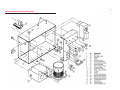
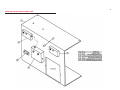
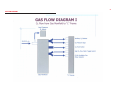
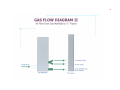
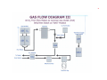
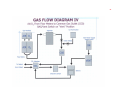
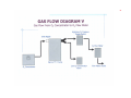
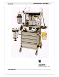
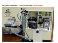
Magellan-2200 Model 2 Anesthesia Machine Service Manual
8005 Shannon Industrial Park Lane
Atchison, Kansas 66002
Tel: 913 874 2000
Fax: 913 874 2005
Email: [email protected]
Version: 082206
2
TABLE OF CONTENTS
PAGE
SUBJECT
• Factory Address and Communications
3
• Purpose
3
• General Poicy
3
• Factory Testing
3
•Equipment and Tools Needed for Service
3
• Routine Testing
4
• Annual Maintenance, Parts Needed and Testing
4
• Exploded View of Ventilator Control Knobs
11
• Testing After Storage
12
• Re-Supply Component Kits and Installation Intervals
12
• Maintenance Components, Kits and Installation Intervals
12
APPENDIX
13
• Specifications of Magellan-2200, Model 2
13
• Problem Solving
15
• Complete List of Part Numbers and Nomenclature
15
• Exploded View Diagrams
19
• Gas Flow Diagrams
21
3
FACTORY ADDRESS AND COMMUNICATION INFORMATION
EQUIPMENT NEEDED FOR BENCH TESTING
Address:
8005 Shannon Industrial Park Lane
Atchison, KS 66005
1. Operators Manual
Phone:
913 874 2000
Fax:
913 874 2005
E-mail:
[email protected]
Website:
www.oceanicmedical.com
Office Hours: Monday through Friday, 08:00 to 16:00 CDT
2. Pre-Use Check List: Contained in this manual, the Operators Manual and Separate
Laminated Card
3. Regulated, Pressurized Gas Sources: Wall outlets for oxygen and air, gas cylinders for
oxygen and air, each with appropriate pressure-reducing regulators, portable medical
grade air compressor and oxygen concentrator.
4. Mechanical or Electrical-Mechanical Test Lung: The factory utilizes the Bio-Med VT-2A
Test Lung, however, other brands of such devices may be used for bench testing
PURPOSE OF THIS DOCUMENT
This Service Manual provides the reader with important information concerning the general
service, maintenance and general repair of the Magellan-2200, Model 2 Anesthesia Machine.
This manual will allow for the service of the Magellan-2200, Model 2 Anesthesia Machine
and its accessories. This machine may be fully serviced outside of the factory and the reader
may contact the factory at any time for assistance.
GENERAL POLICY STATEMENT
The scope of this manual covers general maintenance, calibration of controls, disinfecting
procedures and replacement of certain components at the intervals indicated within this
document.
FACTORY TESTING
Each Magellan-2200, Model 2 Anesthesia Machine is tested utilizing certain testing
equipment which may or may not be available in the field or in a general biomedical
maintenance facility. This manual will explain how the Operator and Biomedical Technician
may completely and safely maintain this equipment.
USE AND OPERATION
The use and operation of the Magellan-2200, Model 2 anesthesia machine should be
performed by a physician, anesthesiologist or certified registered nurse anesthetist (CRNA)
trained properly with this device.
5. Hand-Operated Spirometer: May be used for gas volume calibration if other mechanical
test lungs are not available.
4
6. Rubber Test Lung or Any One Liter Rubber Test Lung or One Liter Gas Reservoir Bag:
Used to simulate patient delivered gas volumes if mechanical Test Lung is not available.
7. Carbon Dioxide Absorber: King Systems KAB-9 unit, either full of absorbent or empty.
8. Patient Tubing Circuit: Any approved Patient Tubing Circuit for Anesthesia may be
utilized.
9. Monitoring Device for Anesthetic Agent: Either a specific vaporized agent testing device
such as a Bickford Anesthesia Agent Tester, Model-3, or an anesthesia monitor capable of
measuring vaporized agent may be used.
10. Tools: The Magellan-2200, Model 2 Anesthesia Machine was designed to be serviced with
the following common tools:
ANNUAL MAINTENANCE, PARTS NEEDED AND TESTING
Recommended Inspection/Replacement of Certain Components
A. Annually: The following procedures should be used to ensure proper operation of the
machine, at least once per year or at any other interval that the Biomedical Technician
deems necessary.
B. Parts Needed: The following parts will be needed for Annual Service
• Inlet Filters (2 each) P/N 11.3
• Bellows, Latex-free, P/N 13.1
1. Changing the Gas Manifold Inlet Filters:
A. 1/16" Allen's Wrench-used with O2 flowmeter control knob and the three ventilator control
knobs.
B. Screwdriver, regular slotted head.
C. Small, adjustable crescent wrench, or:
1. 1/2" open head wrench
2. 7/16" open head wrench
3. regular pliers
D. 1" sealing tape roll
E. Tube of Krytox (or other oxygen compliant) lubricant
F. Water-based leak testing solution
Air (DISS) Inlet Connector:
A. Using a crescent wrench, unscrew the DISS Air inlet connector and remove.
B. Remove the filter spacer (aluminum ring) then remove the cone-shaped filter.
C. Inspect the filter for debris. If debris is found, remove it.
D. Install the filter back into the Gas Manifold (with original or new filter) with the small
end first.
E. Install the filter spacer (aluminum ring).
F. Pull open the one-way valve (located on the end of the threaded portion of the DISS
adapter), and apply some Krytox (or, equivalent) lubricant.
5
G. Re-tape the DISS Air connector, threaded portion, with sealant tape.
2. Replacement of Rubber Bellows and Inspection of Exhalation Diaphragm Valve
H. Re-install the DISS Air connector, screwing it closed, snugly, with the crescent wrench.
A.Removal of Ventilator and Bellows Systems from Main Frame:
1. Turn anesthesia machine on the Vaporizer side of the machine.
Oxygen (DISS) Inlet Connectors:
(the first one is located next to the Air Connector, the second one is located on the left-hand side
of the Gas Manifold and the procedure is identical for both Oxygen DISS Inlet connectors.)
A. Using a crescent wrench, unscrew the DISS Oxygen.
B. Remove the filter spacer (aluminum ring) then remove the cone-shaped filter.
C. Inspect the filter for debris. If debris is found, remove it.
D. Install the filter back into the Gas Manifold (with original or new filter).
E. Install the filter spacer (aluminum ring).
F. Pull open the one way valve (located on the end of the threaded portion of the DISS
adapter) and apply some Krytox (or, equivalent) lubricant.
G. Re-tape the DISS Oxygen connector, threaded portion, with sealant tape.
H. Re-install the DISS Oxygen Connector(s), screwing it closed, snugly, with the crescent
wrench.
2. Using a flat head screwdriver, remove the ventilator retaining screw.
3. Lay the machine down in its normal operating position.
4. Remove the two retaining knob/screws on the backside of the ventilator.
6
5. Disconnect the ventilator gas power tubing from the Ventilator GasPower Toggle Selector
Switch by pushing in on the tubing and simultaneously pushing inwards on the retainer
ring located on the tubing inlet receptacle.
6. Remove the ventilator/bellows system by pulling the assembly forward from the main
frame.
B. Removal of Rubber Bellows from Bellows Base, Inspection of Exhalation Valve
Diaphragm Valve and Installing New Bellows
1. Turn the clear plastic bellows canister cover counter-clockwise until the four plastic
retainer parts are clear of the black plastic retainers, (located on the top of the base of the
bellows assembly) and gently remove the clear plastic bellows canister cover, using an
upwards motion.
2. Remove the rubber bellows from the Bellows Base.
7
3.
Each time the bellows assemblies are opened for inspection and cleaning, all visible
components must be carefully inspected and damaged parts must be replaced.
Bellows: The bellows is an elastomer material and deteriorates over time. Inspect the bellows
every six months if the system is in use. Inspect on the appropriate schedule (annual, to a
period of 3 years) if the system is in long term storage. Replace the bellows if there is any sign
of deterioration.
5. Using Krytox (or equivalent lubricant) place a small amount of the lubricant on the hard
plastic top ring of the bellows.
6. Using Krytox (or equivalent lubricant) place a small amount of the lubricant on the
bottom ring of the clear plastic bellows canister cover.
Exhalation Valve Diaphragm: The exhalation valve diaphragm valve is under the bellow and
can be removed by loosening the three thumbscrews. The valve seat is now visible.
WARNING: During inspection and cleaning (to remove contamination) of the valve seat and
diaphragm, use a soft cloth or brush. Abrasive materials may damage the seat and should not
be used. To preclude damage caused by the patient breathing into the valve, you should use
a bacterial filter in the expiratory breathing circuit.
Clean the seat (A) and the metal disk (B) attached to the base of the diaphragm valve
thoroughly and remove any contamination from the surfaces of both components.
NOTE: Any anesthesia breathing circuit filter may be used.
After cleaning, check the small O-Ring (C) located in the bellows base under the diaphragm
valve is in place. The system will not function if the O-Ring is not in place.
Refit the diaphragm valve assembly to the bellows base and reassemble the bellows
assembly.
4. Install new bellows to bellows base by placing the bottom bellows crease over the lip of
the bellows retainer. (See photos to the right.)
NOTE: Once the bellows is installed, turn the vent/bellows system upside down and observe
that the bellows fully expand and the folds are evenly opened. Re-adjust the bellows fold
where it is attached to the base and re-observe the expansion.
7. Re-install the clear plastic bellows canister cover by pushing the clear canister down
firmly over the bellows base, then turning the canister cover clockwise until the retainers
are completely covered by the retainer clips.
8
8. Re-install the ventilator/bellows system:
A. Place the ventilator/bellows system partially in place.
B. Re-install the ventilator power tubing into the Gas Selector Switch receptacle by pushing
the tubing firmly into the receptacle, then pulling the tubing backwards, firmly.
C. Push the ventilator/bellows system back into its normal position.
D. Re-install the two ventilator base knob-screws from the backside of the machine frame.
E. Turn the entire machine onto the vaporizer side of the system.
F. Re-install the ventilator retaining screw into the bottom of the ventilator through the
bottom of the machine frame.
9
3. Mandatory Replacement of Gas Manifold - High Pressure Color-Coded Tubing
Yellow Tubing Positions From Gas Manifold to:
Every five years or, at any necessary time, each of the 10 color-coded tubes that attaches
to/from the Gas Manifold should be replaced using the following procedure:
A.
Air Pressure Gauge
B.
Air Position on the Ventilator Gas Selector Toggle Switch
C.
Air Flowmeter
A. Green (oxygen) and Yellow (Air) Tubing: The connectors from the Gas Manifold to each of
the following components are of the "push-to-insert-and-lock" type.
II.
ROUTINE FUNCTIONAL TEST : The functional test may be done at annual intervals or at
any time that internal componenets have been replaced.
B. To dismount, push in on the outer ring and pull the tubing out.
NOTE: The Routine and Annual Functional Test may be carried out at any interval. This test will
indicate any malfunction of the machine or its components and the Operator or Biomedical
Technician will be able to rectify any component that is not functioning properly.
NOTE: The end of the color-coded tubing must be squarely cut; angled ends may not seat
properly.
C. To re-insert, push the end of the green tubing into the receptacle and then use a "pulling"
action to lock the tube in place.
Test Procedure:
1. Assemble and install all components needed for routine clinical use of the machine as
outlined in the Operators Manual, or the Laminated Set-Up Card.
2. Perform the Pre-Use Checklist and Laminated Set-Up Card (with photos) in sequence. This
Checklist is contained in the Operators Manual; the separate Pre-Use Checklist laminated
card and Set-Up Card are provided with each machine.
Green Tubing Positions From Gas Manifold to:
A. Auxiliary O2 Flow Selector
B. O2 Pressure Gauge
C.
O2 Flush Valve
D.
O2 Flowmeter
E.
O2 Position on Ventilator Gas Selector Toggle Switch
Calibration Guide in the next section.
F.
O2 Concentrator/High Pressure O2 Selector Toggle Switch
G.
O2 Low Pressure Alarm
CAUTION: If the machine does not pass the Pre-Use Checklist, correct the problem(s)
encountered, then proceed with the Calibration Guide. The Problem Solving Guide on page 13
of this Manual will assist the Operator in resolving possible common problem situations.
H.
O2 Very Low Pressure / O2 Concentrator Pressure Alarm
NOTE: If the machine passes the Pre-Use Checklist with zero problems, proceed to the
10
Calibration Guide:
CAUTION: The factory utilizes pressurized Air and Oxygen set at 50 PSI for all testing. It is
recommended that this pressure be used when possible. If higher or lower inlet pressures are
routinely utilized the ventilator may be re-calibrated at pressure inputs from 40 to 70 PSI.
Calibration Materials Required:
• Source gas of air or oxygen
• Appropriate hose set to connect to gas source
• Pre-Use Checklist
• Operating Ventilator
• Test Lung
• Patient Tubing Circuit
Procedure:
• Attach the patient circuit to the equipment and to the test lung.
• Set Minute Volume control knob to 10 LPM.
• Set Frequency conrol knob to 13 BPM.
• Ensure the bellows is fully inflated.
• Pressurize the ventilator and allow the system to cycle several times.
• Verify the following values on the test lung:
Minute Volume = 10 LPM
BPM
= 13 per minute
Tidal Volume = 770 MI
NOTE: Values should be +/- 10% of settting.
11
2. Ventilator Gas Power Toggle Switch - Select either Air or Oxygen as the power source.
NOTE: Ensure that the Oxygen system toggle switch is in the high-pressure position.
3. Re-Calibration of Individual Control Knobs
Tools needed: Test Lung.
A. Remove Control Knob by grasping the knob firmaly and pulling it straight off the shaft.
B. With the ventilator still cycling, turn the valve shaft until the proper value is shown on
the test lung.
C. Replace the Control Knob by facing the pointer to the desired value and pushing it
straight on to its full extent.
D. Verify the values are now correct.
NOTE: The results of calibration can vary depending on the test lung utilized. Reservoir
bag and rubber test lungs may not inflate fully or over-inflate, causing erroneous results.
III. TESTING AFTER STORAGE
The following procedures should be used after the Magellan-2200, Model 1 Anesthesia
Machine has been stored for 6 MONTHS OR LONGER.
1. Set the machine up and prepare for Bench Testing by placing all components needed on
the machine as though preparing for actual use.
2. Use the Pre-Use Checklist and verify that all components are ready for use.
3. Inspect the machine for gas leaks, such as the high-pressure gas hoses, gas connectors and
pressure-reducing regulators.
4. Allow the machine to function for 30 minutes and re-inspect the device for any
discrepancies.
5. If any problems are observed, perform the Annual Maintenance and test procedure to
re-qualify the machine and return to storage or service.
12
IV.
SERVICE KIT FOR MAGELLAN-2200 ANESTHESIA MACHINES
Part Number
OEM PN with
CAGEC
NSN
Description
A-108
Annual Services Component Kit consists of:
Page No. or
Drawing No.
NOTE: The A-108 Kit is comprised of the following components. Individual components may be utilized
at any interval without installing the complete Kit.
A-108.1
Bellows, Latex free
A-108.2
Tubing Kit with valves
A-108.3
Vaporizer End Caps
A-108.4
Manifold Filters and Spacers
A-108.5
Tweezers for removing Filters and
Spacers
A-108.6
1/16” Allen Wrench
A-108.7
Squeeze Bulb with Common Gas
Outlet Adapter
A-108.8
Tubing, Color Coded
A-108.9
Scavenger Tubing with wye and
Bellows Adaptor
A-108.10
Service Manual CD
A-108.11
Krytox Lubricant Tube, 1/2 oz.
A-108.12
Yoke-type Regulator Washers
13
OTHER COMPONENT SERVICE
1. Vaporizer
Refer to provided Penlon, Ltd. Vaporizer Manual
2. Air Compressors Refer to provided Vortran, Inc. Air Compressor Manual
APPENDIX: (INDIVIDUAL PAGES)
SPECIFICATIONS
Subject
Page Number
SPECIFICATIONS FOR MAGELLAN-2200, MODEL -2
13
PROBLEM SOLVING
15
COMPLETE PARTS LISTING OF ENTIRE ANESTHESIA MACHINE
16
GAS FLOW DIAGRAM
21
MACHINE DIMENSIONS:
Height
53.4 cm
23 inches
Depth
53.4 cm
23 inches
Width
43.2 cm
17 inches
Weight
20.4 kg
45 lbs
Machine Materials
Aluminum, brass and plastic
CASE DIMENSIONS:
Height
66.0 cm
23 inches
Depth
60.96 cm
24 inches
Width
53.34 cm
17 inches
Weight
121.2 kg
200.5 kg
55 lbs (empty)
100 lbs (machine with accessories)
Case Materials
Polyethylene, dyed green
Operating Temperature Range
1.6˚ C to 43.3˚ C (35˚ F to +160˚ F)
Relative Humidity (in use)
30 to 90%, non condensing
Relative Humidity (storage)
40 to 90%, non condensing
Required Gas Supply Sources
• O2 Main and Cylinders
• Air and/or Air Compressor
• Oxygen Concentrator
Flowmeter Fresh Gas Flow
38 to 70 psi (50 psi is optimal)
38 to 70 psi (50 psi is optimal)
3 to 10 psi
1 to above 20 lpm (each flowmeter)
14
Oxygen Flush Valve
Recessed, self-closing, push-button, color coded and
labeled, provides 45-55 lpm constant flow, while
push-button is depressed; may be used sparingly with
O2 concentrator as O2 power source
Oxygen Analyzer/Monitor
OM-25-ME (or equivalent) Galvanic cell sensor, life
expectancy 2 years under normal conditions
Oxygen Analyzer Power Source
2 each AA batteries, life expectancy approx. 3000 use hours
Auxiliary O2 Flow Selector
Scaled 0-10 LPM in set increments, used for pre/post
anesthesia
Vaporizer
Penlon SigmaDelta Series, bolt (cage) mounted,
temperature compensated, very low maintenance
Airway Pressure Gauge
Dual scaled in cmH2O and mmHg, located on front
panel of ventilator
CO2 Absorber System
King Systems KAB-9 (re-fillable) or KAB-1
(pre-filled/disposable)
CO2 Absorber Canister Capacity
400 grams soda lime
Directional Valves
Built in the CO2 Absorber
CO2 Absorber Holding Bracket
Plastic, secured with knob to main frame of machine
Bag-Ventilator Switch/PRV
and Scavenger Outlet Port
Hand-operated selector switch and rotating knob for PRV
and scavenging outlet
Pressure Gauge Tubing
May be attached to bag/vent switch arm or to a point
within the patient breathing circuit (operators choice).
Bellows
Latex free, upward inflating, range from 0 to 1.6 L
Mechanical Ventilator
Bellows Pressure Relief
Pre-set at 60 cmH2O
Pneumatically powered, time cycled, volume constant,
volume variable
Common Gas Outlet
Quick-connect, size indexed
Tubing Circuit
King Systems F-360-61 or any standard anesthesia
circle circuit
Gas Pressure Hoses
DISS and thread indexed, female connectors at both ends
Gas Inlet Manifold
DISS and thread indexed, male connectors with one-way valves
Gas Inlet Manifold Filters
Located behind Manifold Air and O2 inlet male connectors
Gas Inlet Pressure Regulators
• Main supply cylinder
• Safety back up cylinder
DISS/thread indexed for O2
Pin-indexed, yoke mounted for "D" and "E" cylinders for O2
Oxygen and Air Supply Gauges
0-3000 psi range, color coded and clearly labeled
Oxygen Supply Alarms
• Main and safety back-up
• O2 Concentrator
• Alarm power source
• Alarm on/off
Air and O2 Flowmeters
Pneumatically actuated when O2 supply falls below 30psi
Pneumatically actuated when O2 supply falls below 1 psi
9-volt battery located in body of alarm box
Labeled toggle switch located on body of alarm box
Calibrated and scaled 0-10 lpm, color coded, O2
flowmeter has a fluted control knob for easy
identification by touch, alone
Oxygen Concentrator
To power O2 flowmeter only
Air Compressor
May be used to power ventilator and air flowmeter
• Ventilator Pressure Relief
Pre-set to maximum of 60 cmH2O located in main vent box
• Pressure Relief Valve
Preset to 60 cmH2O
Ventilator Gas Power
Requirements
40 to 70 psi, 50 psi optimal
Use toggle switch to select gas source
Waste Gas Scavenger
Positive and negative relief valves, 1 L reservoir bag,
vacuum control knob
Total Machine Gas Leakage
@ 30 cmH2O
@ 80 cmH2O
-0- ml/Min
100 ml/min
Internal System Compliance
@ 20 cmH2O
@ 40 cmH2O
1.1 ml/cmH2O
1.3 ml/cmH2O
Internal System Resistance
@ 1.0 L/sec gas flow
@ 0.5 L/sec gas flow
4.11 cmH2O
1.80 cmH2O
APL Valve Pressure Drop
@ 3.0 L/min gas flow
@ 30 L/min gas flow
0.12 cmH2O
1.03 cmH2O
15
PROBLEM SOLVING GUIDE
PRE USE CHECKLIST
PROBLEM
SOLUTION
Low O2 Pressure Alarm Activates
• Check main pipeline O2 gas supply and the
emergency O2 backup cylinder by observing the gas
pressure gauges. Resolve by ensuring adequate
pipeline and cylinder O2 supplies are adequate and
are attached to anesthesia machine.
Soda Lime in absorber canister
changes color from white to blue
• Replace soda lime in canister
Reservoir Bag does not inflate
• Check Bag/Vent Switch for "vent" position
• Check PRV Control Knob for "closed" position
• Check entire tubing circuit for leaks
Oxygen Sensor does not calibrate
• Check O2 supply and O2 Pressure Gauge
to ensure O2 is available
• Check O2 sensor to ensure proper seating
in "tee" adapter
• Check that opposing (Air or O2) flowmeter is OFF
Ventilator does not cycle
• Check Air or O2 gas power supply for 40-70 PSI on
pressure gauges
• Check Vent Power Selector Switch in
Air or O2 position
• Check expiratory time control to ensure settings
• If O2 is selected for power, check O2 Power Selector
Toggle Switch and ensure it is in the High Pressure
Position
Bellows do not evenly expand or deflate
• Check top white plastic ring for proper lubrication
Bellows holds pressure during
expiratory phase
• Inspect relief valve at base of bellows for debris
Water particles appear in air
flowmeter flowtube
• Insure that water trap is instaled on air inlet located
on the back of the gas manifold
Unwanted postive pressure is indicated on
pressure gauge during end-exhalation
• Remove PEEP valve from system and check for kinks
at ET tube/patient tubing circuit
See Operators Manual
16
PART LIST FOR MAGELLAN-2200, MODEL-1
PART NO.
NSN
DESCRIPTION
PAGE NO.
Listed by Assembly Section, in Bold Type. NOTE: Some numbers are repeated as these are used in additional
assembly.
PART NO.
NSN
DESCRIPTION
PAGE NO.
4.3
1/8" Hose Connector, Locking, 90 degree
DESCRIPTION
PAGE NO.
8.0
Oxygen Pressure Gauge, Green Dial
1.0
"L" Frame, Aluminum with 8-32" Brass Mounting Screws (4 each)
19
7.1
Female/Female Coupling, 1/8" NPT
2.0
Flowmeter Pair, Air and Oxygen with Holding Nuts
19
4.3
1/8" Hose Connector, Locking, 90 degree
2.1
1/8" Hose Barb
20
9.0
Auxiliary Oxygen Flow Selector
2.2
Hose Connector, Locking, Straight
7.1
Female/Female Coupling, 1/8" NPT
2.3
Knob, Green, Fluted for Oxygen Flowmeter
4.3
1/8" Hose Connector, Locking, 90 degree
10.0
Main Body Frame, Aluminum
19
10.1
Support Rods, Brass (2 each)
19
10.2
1/-20 Rod Screws, Brass (4 each)
19
10.3
Dowel Pin for B/V Switch Mounting, Brass with -20 B rass Screw
19
2.1
1/8" Hose Barb, O2 Concentrator Inlet
7.1
Female/Female Coupling, 1/8" NPT
7.2
1/8" Hose Connector, Locking "Y" Outlet
11.0
Gas Manifold Body
20
11.1
DISS Adapter, Air, with one way valve
4
11.2
Spacer, length specific, retains bronze filter
4
11.3
Bronze Filter, cone shaped
4
PART NO.
NSN
Knob, Black, for Air Flowmeter
20
3.0
Common Gas Outlet Body and Holding Nut
19
3.1
Common Gas Outlet Coupling Insert
12 (Ops)
Oxygen Flush Button Assembly
4.1
Gas Actuator Assembly
2.1
1/8" Hose Barb
4.3
1/8" Hose Connector, Locking, 90 degree
5.0
Ventilator On/Off Toggle Switch with Holding Nut
4.3
1/8" Hose Connector, Locking, 90 degree (3 each)
6.0
High Pressure O2/O2 Concentrator Toggle Switch
with Holding Nut
19
20
2.4
4.0
19
19
20
19
19
4.3
1/8" Hose Connector, Locking, 90 degree
11.4
DISS Adapter, Oxygen, with one way valve (2 each)
4
2.2
1/8" Hose Connector, Locking, straight (2 each)
11.5
Spacer, length specific, retains bronze filter (2 each)
4
11.3
Bronze Filter, cone shaped (2 each)
4
2.2
Hose Connector, Locking, Straight (2 each)
4
7.0
Air Pressure Gauge, Yellow Dial
7.1
Female/Female Coupling, 1/8"NPT
19
17
PART NO.
NSN
DESCRIPTION
PAGE NO.
PART NO.
NSN
DESCRIPTION
PAGE NO.
PART NO.
NSN
DESCRIPTION
PAGE NO.
17.0
Bulb, Squeeze/Hi-Lo Pressure Check w/ CGO Adapter and Tubing
11 (Ops)
18.0
Alarm, Low Pressure Mains O2, Container
20
18.1
30 psi, Electric Switch
7.2
1/8" Hose Connector, Locking, "Y" Outlet (3 each)
2.2
Hose Connector, Locking, Straight (2 each)
4
11.6
Nylon Screw Plug
4
12.0
Ventilator Container Main Body
20
18.2
Switch Cover
12.1
Container Front Plate
20
18.3
Alarm Beeper
12.2
Container Back Plate
20
18.4
Alarm Plunger
12.2-A
Container, Top Plate, Bellows Body Attachment Part
20
18.5
9-Volt Battery
12.30
Semi-Locking Control Knobs, (3 ech) Insp Flo/Insp Time/Expir Time 18
19.0
Alarm, O2 Concentrator, Low Pressure, Container
19.1
1 psi, Low Pressure Electric Switch
13.0
Bellows Assembly Complete
19
18.2
Switch Cover
13.1
Clear Plastic Bellows Cover
6
18.5
9-Volt Battery
13.2
Latex-Free Rubber Bellows
6
13.3
Knob-Screws to hold Bellows Assembly to Ventilator Cover Plate
(4 each w/nuts)
6
23.0
Vaporizer Retainer, Aluminum
20
23.1
Retainer Holding Knob-Screws (2 ea)
20
14.0
Bag/Vent Switch/Pressure Relief Valve/Scavenger Outlet
19
24.0
Vaporizer, Agent Specific
20
14.1
B/V Switch Support Arm w/ Connectors for
Reservoir Bag/CO2 Canister Tube
19
24.1
End Cap, Inlet Port for Tubing from Flowmeters, Size Specific
16 (Ops)
24.2
End Cap, Outlet Port for Tubing from Vaporizer to CGO
16 (Ops)
14.2
Pressure Gauge Tubing Connector, w/one way valve
8 (Ops)
24.3
Cagemount Assembly, Backbar and Holding Knobs
16 (Ops)
15.0
CO2 Absorber Support Arm
8 (Ops)
25.0
Manual, Operator and Service on CD25.1
15.1
1/8 x 1/2" Holding Knob and Screw
8 (Ops)
25.1
Penlon Vaporizer Manual
25.2
Set-Up Card, Pictorial
9
20
16.0
Scavenger, Waste Gas
11 (Ops)
25.3
Pre-Use Checklist Card
9
16.1
Scavenger Tubing (3 ea) and "TEE" Adapter
11 (Ops)
26.0
Oxygen Pressure Reducing Regulator, Yoke Mount
6 (Ops)
16.2
Reservoir Bag, 1 Liter
11 (Ops)
PART NO.
PART NO.
DESCRIPTION
DESCRIPTION
PAGE NO.
PAGE NO.
NSN
NSN
18
PART NO.
NSN
DESCRIPTION
PAGE NO.
26.3
Oxygen High Pressure Hose, Green, 24" length
26.4
Oxygen High Pressure Hose, Green, 15' length
6 (Ops)
26.5
Air High Pressure Hose, Yellow, 15' length
6 (Ops)
A-101
Air Compressor, Vortran HP-70
18 (Ops)
A-102
Water Trap for Gas Manifold, Air Inlet Connection
7 (Ops)
A-103
Carrying Case, Air Compressor
A-104
Carrying Case, Magellan-2200 Anesthesia Machine
5 (Ops)
A-105
Oxygen Cylinder Mount for Carrying Case
5 (Ops)
A-106
Aluminum Trolley for Magellan-2200 Anesthesia Machine
A-107
Oxygen Analyzer/Monitor with Sensor
11 (Ops)
A-108
Oxygen Analyzer Sensor Replacement
11 (Ops)
A-108
Oxygen Analyzer TEE Adapter
11 (Ops)
A-109
PEEP Valve, Magnetic
20 (Ops)
A-110
Mapleson/Jackson-Reese CGO Adapter
A-111
Service Kit, Annual Maintenance
12
19
MAGELLAN-2200 ANESTHESIA MACHINE – FRONT
20
MAGELLAN-2200 ANESTHESIA MACHINE – BACK
21
GAS FLOW DIAGRAMS
22
23
24
25