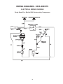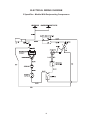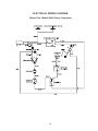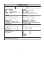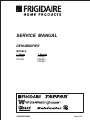
1
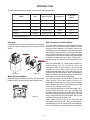
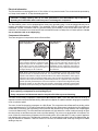
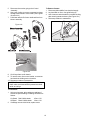
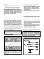
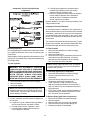
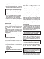
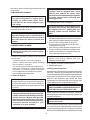
SERVICE MANUAL DEHUMIDIFIER MODELS: 1 Speed FDH25J FDH30J P/N 5995334660 2 Speeds FDD40J FDD50J FDD60J May 2000 TABLE OF CONTENTS SAFE SERVICING PRACTICES - ALL APPLIANCES............ 3 INTRODUCTION Uncrating ........................................................................................................................................... Model & Serial Numbers .................................................................................................................. Basic Operation and Initial Startup ................................................................................................. Electrical Information ....................................................................................................................... Compressor Information .................................................................................................................. OPERATION & REPAIR INSTRUCTIONS 4 4 4 5 5 Bucket ................................................................................................................................................ 6 To Remove Bucket ..................................................................................................................... 6 To Remove Front Grille .................................................................................................................... 6 To Remove Top Cover ...................................................................................................................... 6 To Remove Wrapper ......................................................................................................................... 6 Control Assembly ............................................................................................................................. 7 To Remove Control Assembly ................................................................................................... 7 To Remove Humidistat ............................................................................................................... 7 To Remove Full Bucket Pilot Light........................................................................................ 8 To Test Fan Speed Switch ......................................................................................................... 8 To Remove Fan Speed Switch .................................................................................................. 8 Bucket Switch ................................................................................................................................... 8 To Remove Float: ....................................................................................................................... 8 To Remove Bucket Switch ........................................................................................................ 8 To Test Bucket Switch ............................................................................................................... 9 Defrost Thermostat ........................................................................................................................... 9 To Remove Defrost Thermostat ................................................................................................ 9 To Test Defrost Thermostat ....................................................................................................... 9 Motor, Motor Bracket & Blower Wheel ........................................................................................... 9 To Remove Blower Assembly .............................................................................................. 9-10 To Test Motor ............................................................................................................................ 10 To Remove Casters ......................................................................................................................... 10 Compressor ...................................................................................................................................... 11 Permanent Split Capacitor (PSC) Compressor ...................................................................... 11 Split Phase Compressor ........................................................................................................... 11 To Test Compressor Motor .......................................................................................................11 Possible Causes of Compressor Overloading or Overheating ............................................ 11 Compressor Test Cord for PSC Compressor ......................................................................... 11 Compressor Test Cord for Split Phase Compressor ............................................................ 12 Running Capacitors ................................................................................................................. 12 To Test Capacitor ...................................................................................................................... 12 Compressor Overload Protector ............................................................................................ 12 To Test Overload ...................................................................................................................... 12 To Test Relay (Split Phase Compressor)................................................................................ 12 To Replace Relay (Split Phase Compressor) ......................................................................... 12 1 REFRIGERANT SYSTEM SERVICE INSTRUCTIONS Definitions ....................................................................................................................................... 13 Recovery ................................................................................................................................... 13 Recycling .................................................................................................................................. 13 Reclaim...................................................................................................................................... 13 Safety Warnings .............................................................................................................................. 13 Compressor Testing ................................................................................................................. 13 Charging Sealed Systems ....................................................................................................... 13 Soldering .................................................................................................................................... 13-14 Sealed System ................................................................................................................................. 14 Sealed System Diagnosis Undercharged System ............................................................................................................. 14 Overcharged System ............................................................................................................... 14 Pressure Equalizing (System Unloading) .............................................................................. 14 Refrigerant Leaks ................................................................................................................ 14-15 Component Replacement............................................................................................................... 15 Compressor Replacement ............................................................................................................. 15 To Flush The System ............................................................................................................... 15 To Use Refrigerant To Flush The System .............................................................................. 15 Installing a New Compressor ............................................................................................. 15-16 To Remove Evaporator or Capillary Tube .............................................................................. 16 To Remove Condenser ............................................................................................................ 16 Filter Dryer ................................................................................................................................ 16 Evacuating & Recharging .............................................................................................................. 16 Equipment Needed ................................................................................................................... 16 Installing Evacuation & Recharging Equipment ................................................................... 17 Evacuating System .................................................................................................................. 17 Charging The System .............................................................................................................. 17 Final Leak Test .......................................................................................................................... 17 WIRING DIAGRAMS - DATA SHEETS Electrical Wiring Diagrams Single Speed Fan - Models with Reciprocating Compressors ............................................ 18 Two Speed Fan - Models with Reciprocating Compressors ................................................ 19 Two Speed Fan - Models with Rotary Compressors ............................................................. 20 Dehumidifier Rating Sheets Models FDH25J & FDH30J....................................................................................................... 21 Model FDD40J........................................................................................................................... 22 Model FDD50J........................................................................................................................... 23 Model FDD60J........................................................................................................................... 24 2 SAFE SERVICING PRACTICES - ALL APPLIANCES To avoid personal injury and/or property damage, it is important that Safe Servicing Practices be observed. The following are some limited examples of safe practices: 1. DO NOT attempt a product repair if you have any doubts as to your ability to complete it in a safe and satisfactory manner. 2. Before servicing or moving an appliance: Remove the power cord from the electrical outlet, trip the circuit breaker to the OFF position, or remove the fuse Turn off the gas supply Turn off the water supply 3. Never interfere with the proper operation of any safety device. 4. USE ONLY REPLACEMENT PARTS CATALOGED FOR THIS APPLIANCE. SUBSTITUTIONS MAY DEFEAT COMPLIANCE WITH SAFETY STANDARDS SET FOR HOME APPLIANCES. 5. GROUNDING: The standard color coding for safety ground wires is GREEN, or GREEN with YELLOW STRIPES. Ground leads are not to be used as current carrying conductors. It is EXTREMELY important that the service technician reestablish all safety grounds prior to completion of service. Failure to do so will create a hazard. 6. Prior to returning the product to service, ensure that: All electrical connections are correct and secure All electrical leads are properly dressed and secured away from sharp edges, high-temperature components, and moving parts All non-insulated electrical terminals, connectors, heaters, etc. are adequately spaced away from all metal parts and panels All safety grounds (both internal and external) are correctly and securely connected All panels are properly and securely reassembled WARNING This service manual is intended for use by persons having electrical and mechnical training and a level of knowledge of these subjects generally considered acceptable in the appliance repair trade. Frigidaire cannot be responsible, nor assume any liability, for injury or damage of any kind arising from the use of this manual. 3 INTRODUCTION This Service Manual may be used to service the following Dehumidifiers: Siz e Speed C ontrol C ompressor C ompressor Motor FD H25J 25 Pi nt 1 Speed Reci procati ng Spli t Phase FD H30J 30 Pi nt 1 Speed Reci procati ng Spli t Phase F D D 40J 40 Pi nt 2 Speed / Hi -Lo Reci procati ng Spli t Phase F D D 50J 50 Pi nt 2 Speed / Hi -Lo Rotary PSC * F D D 60J 60 Pi nt 2 Speed / Hi -Lo Rotary PSC * Model * Permanently Spli t C apaci tor Uncrating Basic Operation and Initial Startup Uncrating instructions are clearly printed on the shipping carton. See figures 4a and 4b to remove the unit from the carton. The Dehumidifier consists of a small refrigeration system and a fan. The fan moves the moisture-laden air over the evaporator and condenser. The moisture from the air condenses on the cold evaporator surface where it drips into a bucket. A drain hose can be connected to the bucket. The cool air then passes over the warm condenser, raising its temperature. Since this air contains less moisture and is warmer, its relative humidity is lower. This drier air is expelled through the side grille and mixes with the room air. Figure 4a Place the Dehumidifier on a level surface with all four casters resting firmly on a solid floor. Since the dehumidifier draws in air through the front grille and exhausts out the left side louvers, the unit may be positioned against a wall, but care should be taken not to obstruct this air flow with furniture, walls, etc. Maintain at least 2 feet clearance at left side and front. Shut all doors and windows to the area to be dehumidified. Figure 4b Model & Serial Numbers For the first operation, turn the Humidity Control to the MAX position. This aids moisture removal from furnishings as well as room air. When you feel a desired level of dryness has been reached, adjust the Humidity Control to your particular comfort level. Model and Serial numbers are found on the Serial Plate located on the Front Panel directly behind the Bucket. Prior to emptying the bucket, turn the Dehumidifier OFF and disconnect the power cord. This eliminates any possibility of electrical shock if you spill water, and there is a fault in the grounding system of the unit or your home wiring. Ensure the area, the Dehumidifier, and you are dry before reconnecting the power cord. Figure 4c A light coating of frost on the coil is normal when the Dehumidifier is first turned "ON". Under normal conditions, it will disappear in 30 to 45 minutes. If it doesnt disappear, shut if off, and wait for it to defrost before running again. 4 Electrical Information The Dehumidifier must be plugged into a 115 Volt, 60 Hz, AC only electrical outlet. The circuit should be protected by a 15 Amp circuit breaker or 15 amp time-delay type fuse. CAUTION: If voltage varies by ±10% of 115 volts, performance of the Dehumidifier may be affected. Operating the Dehumidifier with insufficient power can damage the compressor. The Dehumidifier power cord is equipped with a three prong grounding plug. It must be plugged directly into a properly grounded three prong receptacle. The receptacle must be installed in accordance with local codes and ordinances. A power cord about 6 feet long permits locating a unit suitably in most homes without the use of an extension cord. An extension cord can become a shock hazard if it rests on a damp floor or if water spills on it. Do not use an extension cord or an adapter plug. Compressor Information There are two types of compressors used on Dehumidifiers: Low-Side R eciprocating Piston C ompressor H igh-Side R otary C ompressor Thi s c o mp re s s o r o p e ra te s wi th lo w-s i d e o r sucti on pressure wi thi n the compressor shell. Refri gerant vapor from the evaporator i s drawn i nto the shell to cool the motor wi ndi ngs before b e i ng c o mp re s s e d . Hi g h p re s s ure va p o r i s di scharged di rectly i nto the condenser. Thi s compressor draws low pressure refri gerant va p o r f r o m t h e e va p o r a t o r d i r e c t l y i n t o t h e compressi on chamber. Hi gh pressure vapor i s di scharged i nto the compressor shell where i t pi cks up excess motor heat before passi ng i nto the condenser. N OTE : Rotary compressors take longer to start the refri gerati on process than reci procati ng co mp re sso rs a fte r a n e xte nd e d d o wn ti me . The re a so n i s tha t whi le the te mp e ra ture o f the evaporator and condenser change wi th the fluctuati on of the ambi ent temperature, nei ther type of compressor can provi de a temperature stable mass. And, si nce all of the refri gerant i n the system condenses i n the compressor shell duri ng extended i dle peri ods, the "hi gh-si de" rotary compressor depends upon heat generated by the motor and compressor to vapori ze the refri gerant and pump i t through the system. On the other hand, the "low-si de" reci procati ng compressor qui ckly lowers the pressure on the li qui d causi ng i t to vapori ze faster and i mmedi ately pump i t through the system. CAUTION: Replacement compressors are charged with oil at the factory. Care should be exercized when replacing a compressor to avoid spilling any oil. Rotary compressor hold down nuts must be torqued to 50 in/lbs to prevent loosening. The motor for the Rotary compressor is a Permanent Split Capacitor (PSC ) motor with Start and Run windings. A capacitor is wired in series with the Start winding. When power is applied, the capacitor assists in bringing the compressor motor to optimum speed. The motor for the Reciprocating compressor is a Split Phase. This compressor has a Start and Run winding, with a current activated relay or PTC (Positive Temperature Coefficient) relay. When power is applied to the Run winding (on models with current relay), the high starting current pulls the relay armature up, closing contacts, and completing the circuit to the Start winding. The motor starts and accelerates to a point where the current is reduced enough to allow the relay to drop out and disconnect the circuit to the Start winding. This point occurs at about 80% of full speed. The motor continues to accelerate to full speed on the Run winding alone. On models with PTC relay, current is applied to both windings at the same time. This starts the compressor. As current flows through the relay to the Start winding, the relay will increase in resistance . Within a fraction of a second, the resistance will climb high enough for the Start winding to drop out. 5 OPERATION & REPAIR INSTRUCTIONS Bucket The bucket is mounted to the front of the chassis and is located beneath the cooling coil to catch the condensate. A float mounted on the bucket is used to activate a switch to shut off the unit when the bucket is full of water. If the unit is to be installed near a floor drain, a permanent drain hose may be attached to the threaded hose connection on the bucket. If you want water to flow directly into the drain, place the hose connection of the bucket directly over the drain. When using either method of draining, a plastic membrane in the hose connection of the bucket must be cut out in order to permit the water to flow into the hose or drain. To return to bucket collection, the hose connection may be closed with a standard threaded cap. Figure 6a Figure 6b To Remove Bucket 1. Disconnect dehumidifier from electrical supply. 2. Pull bucket toward you, releasing actuator from float assembly. (See Figures 6a and 6b.) 3. Reverse procedure to complete repairs. Figure 6c To Remove Front Grille Figure 6d To Remove Wrapper 1. Disconnect dehumidifier from electrical supply. 2. Remove two screws at lower front of grille. (See Figure 6b.) Note: Bucket must be removed to gain access to these screws. 3. Remove two screws in upper holes in rear of cabinet flange. (See Figure 6d.) 4. Pull grille toward you so the two pins on each side of grille will pull free of holes in cabinet. (See Figure 6c and 6d.) 5. Pull grille down to release from top cover. 6. Reverse procedure to reassemble. 1. Disconnect dehumidifier from electrical supply. 2. Remove front grille and top cover. 3. Remove 14 screws from wrapper as shown in Figures 6e and 6f. To Remove Top Cover 1. Disconnect dehumidifier from electrical supply. 2. Remove front grille. 3. Remove two screws on rear of dehumidifier holding top cover to cabinet. (See Figure 6d.) 4. Slide cover to rear to release tabs from flange. Figure 6e Figure 6f 4. Grasp wrapper on its left and right sides, pulling outward, then pull toward you and lift free of dehumidifier. 5. Reverse procedure to reassemble. NOTE: The Control Assembly is attached to the top cover. This must be removed before the top cover can be lifted up and off of the unit. 5. To release the Control Assembly from the top cover, press in on the four tabs, on the underside of the top cover. (See Figure 6g.) Electrical wires are still connected to assembly, so be careful. 6. Lift cover up and off. 6. Reverse procedure to reassemble. Tabs Tabs 6 Figure 6g Control Assembly 4. Disconnect two black wires and one red wire connected to Fan Speed Switch. (Only on two speed models.) 5. Remove control assembly. 6. Reverse procedure to reassemble. The overlay of the Control Assembly for the two speed models displays an Humidity Control Switch, (humidification min. to max. range), Fan Speed Switch (HI and LO), and a Bucket Full LED. (See Figure 7a1.) On the single speed model, there is no Fan Speed Switch. (See Figure 7a2.) A Humidistat cycles both the fan and compressor ON or OFF to maintain humidity at the set level. The humidity sensing element is a nylon film which stretches with increased humidity and contracts with decreased humidity. This action turns a switch in the control ON and OFF to cycle the unit. To Remove Humidistat 1. Disconnect dehumidifier from electrical supply. 2. Remove control knob from front of control assembly. 3. Disconnect three black wires connected to two terminals on Humidistat. 4. Pull back on four tabs to release the humidistat. (See Figure 7c.) Pull back on top tabs first, tilting humidistat towards you, then pull back on bottom tabs and pull humidistat free from assembly. 5. Reverse procedure to reassemble. Figure 7a1 Figure 7a2 To Remove Control Assembly Figure 7c 1. Disconnect dehumidifier from electrical supply. NOTE: See Figure 7b for location of electrical wires. 2. Disconnect one red and two white wires connected to Bucket Full Light. (One of the white wires is pigtailed to the red wire on one of the terminals.) 3. Disconnect two black wires connected to Humidistat. Figure 7b 7 To Remove Full Bucket Pilot Light Bucket Switch 1. Disconnect dehumidifier from electrical supply. 2. Disconnect three wires connected to two terminals on pilot light. (See figure 7b.) 3. Using needle nose pliers, squeeze plastic tabs against pilot light and push light through hole in assembly. (See Figure 8a.) The bucket switch is a Single Pole, Double Throw (SPDT) device that shuts off the dehumidifier when the bucket is full. The switch is activated by a float (see Figure 8c) mounted inside the bucket. The switch is mounted to the frame directly behind the bucket. (See Figure 8d.) NOTE: This unit will not operate with the bucket removed. Figure 8a Figure 8c To Test Fan Speed Switch (2 speed models only) Figure 8d To Remove Float: 1. Disconnect dehumidifier from electrical supply. 2. Disconnect three wires connected to three terminals on fan switch. 3. Using a multimeter on resistence scale, take following readings: (See Figure 8b.) With fan switch in HI: Terminals 1 & 2 0 ohms Terminals 1 & 3 max resistence Terminals 2 & 3 max resistence With fan switch in LO: Terminals 1 & 2 max resistence Terminals 1 & 3 0 ohms Terminals 2 & 3 max resistence 1. Disconnect dehumidifier from electrical supply. 2. Remove bucket. (See procedure To Remove Bucket on page 6.) 3. Drain any condensate that may be in the bucket. 4. Remove pin holding float to bucket. (See Figure 6e.) 5. Remove float through top access hole in bucket. 6. Reverse procedure to reassemble. Figure 8e NOTE: When reinstalling float into bucket, ensure the float is positioned so the tongue protrudes through the front hole in the bucket. Then the pin is inserted through the hole in the tongue and snapped into the slot in the bucket. To Remove Bucket Switch: 1. Disconnect dehumidifier from electrical supply. 2. Remove three electrical leads from terminals on bucket switch. 3. Squeeze tabs together and push up on switch from bottom. (See Figure 8f.) Figure 8b To Remove Fan Speed Switch (2 speed models only) The Fan Speed Switch is very difficult to remove without destroying it. Do not attempt to remove the switch unless it is faulty. Then, it really doesnt matter if the switch is damaged during removal. However, do be careful not to damage the control assembly during removal. The new switch will fit into place nicely once the faulty switch has been removed. Figure 8f 8 To Test Bucket Switch: To Test Defrost Thermostat: 1. Test resistance between three terminals on switch. (See Figura 9a.) 2. Using Multimeter on resistance scale, with switch in AT REST position, resistance readings should be as follows : Common - Normally Open = Max. resistance Common - Normally Closed = Zero resistance With switch arm DEPRESSED, readings should be as follows: Common - Normally Open = Zero resistance Common - Normally Closed = Max. resistance 3. Replace switch if readings are not within range. 1. Using Multimeter on resistance scale, read resistance of thermostat between the two leads. At room temperature (above 60°F), resistance should be zero (0), indicating the thermostat is closed. 2. To see if thermostat opens when temperature drops to 37°F, bury thermostat in bucket of ice. With multimeter still connected to two thermostat leads, watch resistance scale to see if it goes to maximum when temperature drops to 37°F. (Place thermometer in ice bucket to monitor exact temperature at which thermostat opens.) 3. Replace thermostat if readings are not within limits. NOTE: When replacing the thermostat, make sure the insulation is wrapped firmly around the thermostat to prevent heat loss. Motor, Motor Bracket and Blower Wheel The shaded pole Fan Motor can be single or two speed, depending on the model. The motor turns a Blower Wheel (7 L x 2 W) rather than a fan blade.This motor does not have a Start winding, but instead employs a shading coil in the stator to produce starting torque in the proper direction. When the motor speeds up, the shading coil does not affect the motors operation. Figure 9a Defrost Thermostat The defrost thermostat is mounted on the suction line close to the compressor. When the ambient temperature drops below 65°F, the evaporator coil temperature also drops and frost begins to form on the evaporator surface. When the suction line temperature reaches 37°F at the location of the defrost thermostat, the thermostat opens the circuit to the compressor. When the accumulated frost melts and the suction line has warmed to 59°F, the defrost thermostat closes, allowing the compressor to restart. The fan motor will continue to run when thermostat is open. The fan motor is permanently lubricated. However, some motors have oil ports and should be oiled after two years of service. To Remove Blower Assembly 1. Disconnect dehumidifier from electrical supply. NOTE: Refer to procedures on page 6 to remove bucket, front grille, top cap and wrapper. To Remove Defrost Thermostat: 1. Disconnect dehumidifier from electrical supply. 2. Remove bucket, front grille, top cap and wrapper. 3. Remove four screws from motor bracket. (See Figure 9c.) 4. Pull blower assembly towards you and lift up and out of unit. (See Figure 9d.) NOTE: Refer to procedures on page 6 to remove bucket, front grille, top cap and wrapper. 2. Remove bucket, front grille, top cap and wrapper. 3. Locate defrost thermostat just above compressor on suction line.0 4. Disconnect two wire leads from thermostat. 5. Remove insulation from around Defrost Thermostat so spring clip is exposed. 6. Press on spring clip with thumb and raise thermostat free from evaporator coil.(See Figure 9b.) 7. Reverse procedure to reassemble. Figure 9b Figure 9c 9 Figure 9d To Remove Casters 5. Disconnect three wires going to the Control Assembly. 6. Use a pair of pliers to remove compression clamp holding blower wheel to motor shaft. (See Figures 10c and 10d.) 7. Pull blower wheel off of motor shaft and free from blower assembly. 1. 2. 3. 4. Disconnect dehumidifier from electrical supply. Lay humidifier on floor, front grille facing up. Use a hammer and screwdriver to release locking tabs securing casters to base. (See Figure 10c.) Reverse procedure to reassemble. Figure 10c Figure 10c Figure 10d 8. Lift off styrofoam scroll chassis. 9. To remove motor from motor bracket, remove two hex head nuts holding motor to bracket. 10. Reverse procedure to reassemble. NOTE: When reassembling blower wheel to motor shaft, make sure blower wheel is pressed onto shaft as far as it will go. To Test Motor 1. Using an ohmmeter, take resistance readings of HI and LO speed windings. Readings should be as follows: LO Speed Red & White leads HI Speed Black & White leads 45W ± 10% 30W ± 10% 2. If readings are not within limits, replace motor. 10 Compressor 1. Disconnect dehumidifier from electrical supply. 2. Remove leads from compressor terminals. 3. Check for grounded windings by testing continuity from each terminal to any copper tubing connected directly to compressor. If continuity is indicated, motor windings are grounded and compressor will have to be replaced. 4. Check for open windings by checking continuity from Start-to-Run terminals. If no continuity is found, a winding is open and compressor must be replaced. Possible Causes of Compressor Overloading or Overheating There are two types of compressors used on dehumidifiers: 1. Permanent Split Capacitor compressor (Rotary) 2. Split Phase compressor (Reciprocating) Permanent Split Capacitor (PSC) Compressor This compressor has a Start and Run winding with a capacitor wired in series with the Start winding. When power is applied, the capacitor assists in bringing the compressor motor to optimum speed. Split Phase Compressor This compressor has a Start and Run winding. On models equipped with a current activated relay, the relay is wired in series with the Run winding. When power is applied to the Run winding, The high starting current pulls the relay armature up, closing contacts to complete the circuit to the Start winding. The motor starts and accelerates to a point where the current is reduced enough to allow the relay to drop out and disconnect the circuit to the Start winding. This point occurs at about 80% of full speed. The motor continues to accelerate to full speed on the Run winding alone. On models with PTC relay, current is applied to both windings at the same time. This starts the compressor. As current flows through the relay to the Start winding, the relay will increase in resistance . Within a fraction of a second, the resistance will climb high enough for the Start winding to drop out. CAUTION: Replacement compressors are charged with oil at the factory. Care should be exercized when replacing a compressor to avoid spilling any oil. 1. Shorted winding. Recheck Start and Run windings. 2. Low voltage. With dehumidifier disconnected, check voltage at electrical outlet. Voltage should be of 115 VAC,+/- 10%. 3. Plug in dehumidifier and check voltage. If voltage is not within +/- 10% of 115 VAC, compressor break down or overheating may occur. Excessive voltage drop during start-up or while running may be cause of motor overload opening. 4. Defective run capacitor (if supplied). If compressor will not start (or starts slowly), or compressor runs but draws high current, test capacitor. 5. Dirty evaporator and/or condenser. 6. Insufficient air passing over condenser. The compressor can also be operated on a test cord when connected as illustrated below. CAUTION: If compressor is a permanent split capacitor type, use only a known good electrolytic capacitor, rated for compressor being tested. This running capacitor must be in circuit while compressor is running. To Test Compressor Motor WARNING: WHENEVER TESTING A COMPRESSOR, EXTREME CAUTION SHOULD BE USED TO PREVENT DAMAGING THE TERMINALS. A COMPRESSOR WITH A DAMAGED TERMINAL OR A GROUNDED WINDING CAN EXPEL A TERMINAL FROM ITS INSULATED HOUSING WHEN THE COMPRESSOR IS ENERGIZED. IF THIS HAPPENS, A MIXTURE OF REFRIGERANT AND OIL WILL BE RELEASED THAT CAN BE IGNITED BY AN EXTERNAL HEAT SOURCE (OPEN FLAME, HEATER, ETC.). ALSO, IF THERE IS AIR IN THE SYSTEM WHEN THIS HAPPENS, A SPARK AT THE COMPRESSOR SHELL COULD IGNITE THE REFRIGERANT AND OIL MIXTURE. Compressor Test Cord for PSC Compressor NOTE: If compressor has a permanent split capacitor (PSC) motor, running capacitor should be tested first. 11 Compressor Test Cord for Split Phase Compressor d. If needle jumps toward zero and falls back to constant high resistance value (not infinity), capacitor has high resistance leak. e. Check for ground from each terminal of capacitor to bare metal of capacitor case. Resistance should be infinite. If resistance is less than infinite, capacitor is grounded. Replace capacitor if it is open, shorted, grounded or has a high resistance leak. Compressor Overload Protector An overload protector is attached to the compressor to detect excessive heat or a current overload. If the overload is actuated, it will shut off the current to the compressor and automatically reset itself after a short cool down period. The compressor will attempt to start after the cool down period. The overload is located under the terminal cover. To gain access to the overload, disconnect the dehumidifier from the electrical supply and remove the terminal cover. Running Capacitors To Test Overload Running capacitors are used on some compressor motors to increase the efficiency of the motor by improving the power factor. 1. 2. 3. 4. Always replace running capacitors with capacitors of like type and mF (microfarad) rating. Pay particular attention to the voltage rating. To Test Capacitor Disconnect dehumidifier from electrical supply. Remove wrapper. Remove terminal cover. Disconnect all wiring to overload and check across overload terminals with ohmmeter. (Overload should be at room temperature when checked.) Zero ohms (0W) should be indicated. NOTE: Always replace terminal cover and gasket to protect overload and compressor terminals from moisture and corrosion. WARNING: AN INTERNALLY SHORTED CAPACITOR MAY EXPLODE IF ENERGIZED DIRECTLY WITH LINE VOLTAGE. CHECK ONLY WITH AN OHMMETER OR CAPACITOR TESTER. AFTER TESTING, A LWAYS DISCHARGE CAPACITOR WITH A 20,000W (OHM), 2 WATT RESISTOR PLACED ACROSS THE TERMINALS. To Test Relay (Split Phase Compressor) 1. Disconnect dehumidifier from electrical supply. 2. Remove relay and overload cover from compressor. 3. Disconnect wire to relay and remove relay from compressor terminals (pull straight off). 4. Check continuity of relay coil (refer to wiring diagram for proper terminals to check across). If relay coil checks OK, use compressor test cord to test compressor. 5. If PTC relay is used, check resistance between L1 and Start winding. Resistance should be no more than 4 ohms at room temperature. 1. Disconnect dehumidifier from electrical supply. 2. Remove wrapper. 3. Discharge capacitor. NOTE: Best method of discharging capacitor is with insulated copper wire in series with a 20,000 ohm, 2 watt resistor. Place this high resistance jumper across capacitor terminals. To Replace Relay (Split Phase Compressor) 4. Disconnect capacitor wiring. 5. Connect ohmmeter across terminals of capacitor to be checked: 1. 2. 3. 4. 5. a. If capacitor is good, needle should jump toward zero ohms and quickly drop back to infinity. b. If needle does not move, capacitor is open. c. If needle reads constant value at near zero ohms, capacitor is shorted. 12 Disconnect humidifier from electrical supply. Remove wrapper. Remove relay cover from relay and overload. Remove wire from relay and pull straight off. Reverse procedures to reassemble. REFRIGERATION SYSTEM & SERVICE NOTICE: Instructions given here are furnished as a guide. Persons attempting to use these instructions to make repairs to the sealed refrigeration system should have a working knowledge of refrigeration, previous training on sealed system repair, and an EPA certification for servicing refrigeration systems. IMPORTANT NOTICE Effective July 1, 1992, the United States clean air act governs the disposal of refrigerants such as R-22. Therefore, when discharging or purging the sealed system, use an EPA approved refrigerant recovery system as outlined in the final rule on the protection of stratospheric ozone and refrigerant recycling which was published in the Federal Register May 14, 1993. NOTE: Frigidaire does not permit the use of recovered refrigerant in the servicing of our products for in-warranty and out-of-warranty repairs or for products covered by service contracts. Therefore, only new refrigerant or refrigerant that has been reclaimed back to new specifications by a refrigerant manufacturer is to be used. followed by a sequence of circumstances, can lead to the compressor shell seam separating. DEFINITIONS Recovery: to remove refrigerant in any condition from a system and store it in an external container without necessarily testing or processing it in any way. A hydraulic block then occurs, preventing the compressor from starting. This condition is known as locked rotor. Electric current continues to flow through the compressor motor windings which become, in effect, electric resistance heaters. The heat produced begins to vaporize the excess refrigerant liquid, causing a rapid increase in system pressure. If the compressor protective devices fail, the pressure within the system may rise to extremes far in excess of the design limits. Under these conditions, the weld seam around the compressor shell can separate with explosive force, spewing oil and refrigerant vapor which could ignite. Recycling: to clean refrigerant for reuse by oil separation and single or multiple passes through devices, such as replaceable core filter-driers, which reduce moisture, acidity and particulate matter. This term usually applies to procedures implemented at the field job site or at a local service shop. Reclaim: to reprocess refrigerant to new product specifications by means which may include distillation. Will require chemical analysis of the refrigerant to determine that appropriate product specifications are met. This term usually implies the use of processes or procedures available only at a reprocessing or manufacturing facility. To eliminate this exceedingly rare but potential hazard, never add refrigerant to a sealed system. If refrigerant is required, evacuate the existing charge and recharge with the correct measured amount of the refrigerant specified for the system. SAFETY WARNINGS SOLDERING Compressor Testing WARNING: WEAR APPROVED SAFETY GLASSES WHEN WORKING WITH OR ON ANY PRESSURIZED SYSTEM OR EQUIPMENT. HAVE AN APPROVED DRY TYPE FIRE EXTINGUISHER HANDY WHEN USING ANY TYPE OF GAS OPERATED TORCH. Whenever testing a compressor, extreme caution should be used to prevent damaging the terminals. A compressor with a damaged terminal or a grounded winding can expel a terminal from its insulated housing when the compressor is energized. If this happens, a mixture of refrigerant and oil will be released that could be ignited by an external heat source (open flame, heater, etc.). Also, if there is air in the system when this happens, a spark at the compressor shell could ignite the refrigerant and oil mixture. 1. All joints to be soldered must have proper fit. Clearance between tubes to be soldered should be from .001 to .006. It is not practical to actually measure this; however, you do not want dry fit or loose fit. Tubing joints should overlap about distance of their diameter except for restrictor tubes, which should be inserted 1.25 2. Clean all joint areas with fine steel wool or, preferably, abrasive cloth, such as grit cloth No. 23 or Scotch-Brite. Charging Sealed Systems Overcharging a refrigeration system with refrigerant can be dangerous. If the overcharge is sufficient to immerse the major parts of the motor and compressor in liquid refrigerant, a situation has been created which, when 13 Overcharged System 3. Apply thin film of liquid flux recommended for silver soldering to surfaces to be joined, and to surfaces immediately adjacent to joint. 4. Align tubing so no stress is on joint. Do not move tubing while solder is solidifying or leaks will result. Operate the unit for at least 30 minutes in a room temperature of 75°F to 85°F. The top of the compressor should be warm to the touch. This applies to a reciprocating compressor only. If it is cool or cold, the system is possibly overcharged. On models eqipped with Rotary compressors, check for frost or cold temperatures all the way to the top of the accumulator. CAUTION: During application of heat, use wet cloths to prevent heat from conducting to areas other than soldered joint. Use a sheet of metal as a heat deflector to keep flame away from flammable materials and painted surfaces. An overcharged system must be evacuated and recharged. Purging off excess refrigerant is not legal or practical, as there is no way of determining the amount to purge. 5. Use torch of adequate capacity so joint can be quickly heated with minimum of heat travel to other points. Use good grade of silver solder. 6. Solder connections. If tubing is properly cleaned and fluxed, solder will flow readily. Use only enough solder to make a good bond. 7. Allow joint to cool, then wash exterior with water to remove flux. Pressure Equalizing (System Unloading) If an attempt is made to start the unit too soon after it has stopped, the compressor may fail to start and will cycle on the overload protector. This is caused by high head pressure and low suction pressure. Allow the pressures to equalize through the capillary tube. Pressure equalizing (system unloading) will usually take 2 to 3 minutes. SEALED SYSTEM Refrigerant Leaks The dehumidifying system is similiar to that of a room air conditioner, except for size. The condenser and evaporator are both fin and tube coils of copper tubing with aluminum fins. Both coils are placed in the air stream. An undercharge of refrigerant is usually caused by a leak in the system. Such leaks must be located, the refrigerant recovered, and the leak repaired before evacuating and recharging. Simply adding the refrigerant or recharging will not permanently correct the problem and may lead to a compressor burn out. A capillary tube controls the refrigerant flow from the condenser to the evaporator. The suction tube from the evaporator outlet to the compressor is insulated to prevent sweating. NOTE: Do not replace a component because the system is undercharged unless a nonrepairable leak is found within the system components. NOTE: Check the performance of the dehumidifier and electrical system before attempting to repair the sealed system. If a leak cannot be readily found, the system should be pressurized to at least 75 psig (gauge pressure). If necessary, attach a ¼ line piercing valve to the compressor process tube and add enough refrigerant for testing. (Only use the refrigerant specified on the serial nameplate.) SEALED SYSTEM DIAGNOSIS Undercharged System Disconnect fan motor leads and start the unit. A slight, uniform film of frost should form on the entire evaporator within about 10 minutes. If it does not, the system is possibly undercharged. NOTE: The line piercing valve (clamp-on type) should be used for test purposes only. It must be removed from system after it has served its purpose. If an undercharged system is found, perform the following: Most leaks can be found with a Halide torch. However, for very small leaks, it may be necessary to use an Electronic Leak Detector, or the soap bubble method to pinpoint the leaks. Leak test unit. Recover refrigerant. Repair Leak. Evacuate and recharge unit with proper amount of refigeratant. CAUTION: Be sure the system has a positive pressure before using the soap bubble method of leak detecting. A vacuum within the system could draw in moisture and contaminants. NOTE: Always leak test system after recharging. After servicing a system, always leak test the entire system, especially new joints before final recharging. Clean off any soldering flux, if used, from the joints before 14 leak testing, as flux can seal off pinhole leaks that would show up later. CAUTION: The end of flushing hose of tank regulator must be equipped with a hand shut-off valve (Robinair No. 40380). Close hand shut-off valve and adjust nitrogen regulator to correct pressure before proceeding with flushing procedure. COMPONENT REPLACEMENT CAUTION: It is extremely important to verify the type of refrigerant in a system before starting any sealed system repair. Check serial plate for the correct refrigerant type and charge. To Use Refrigerant To Flush The System: CAUTION: Refrigerant used for flushing must be captured in a recovery bag. Meter amount of refrigerant used for flushing with your charging cylinder. DO NOT OVERFILL THE BAG. When replacing components, all copper joints must be joined with silver solder or Sil-Fos. CAUTION: Be careful not to damage adjacent parts when using a torch on soldered joints. If necessary, use a metal heat shield, or wrap a wet cloth around the tubing to reduce heat transfer. 1. Remove suction and discharge lines on compressor and disconnect capillary tube from condenser. Connect process coupling to outlet and inlet tube of condenser. 2. Connect hose to outlet process coupling and charging cylinder. Connect another hose to inlet coupling and recovery bag. 3. Open charging cylinder and allow refrigerant to flow through condenser until discharge into bag is clear. 4. Connect process fitting to compressor suction line. Flush evaporator and capillary tube. COMPRESSOR REPLACEMENT CAUTION: NEVER install a new compressor without first checking for possible system contamination. To check for contamination, obtain an oil sample from an old compressor. NOTE: If unable to get refrigerant flow through capillary tube, remove capillary tube from evaporator and flush again. If oil has burned odor, but no color change or residue follow instructions in section Installing A New Compressor on page 14. If oil has burned odor and shows contamination (dark color) or feels gritty follow instructions in next section, To Flush The System. Remove as much contamination as possible from system before installing new compressor. 5. If cap tube is blocked, replace cap tube. 6. Reassemble system. Installing a New Compressor All replacement compressors are shipped with rubber plugs in the suction, discharge, and process tubes and contain the correct oil charge and a holding charge of inert gas. Models with Reciprocating Compressors have a low-side process tube attached to the compressor shell. Models with Rotary Compressors have a process tube on the high side of the system soldered into the compressor discharge line To Flush The System NOTE: The system should be flushed with dry nitrogen. However, you must use R-22 if refrigerant is used to flush system. This is the only refrigerant that can be used to flush the system and it must be recovered. WARNING: DO NOT OPERATE COMPRESSOR WHEN CHARGING LIQUID REFRIGERANT INTO SYSTEM THROUGH ITS PROCESS TUBE. CAUTION: Use extreme care when using dry nitrogen to flush systems. Pressure in nitrogen cylinder could be as high as 2000 psi. Nitrogen cylinder must be equipped with approved pressure regulator and pressure relief valve. Ensure that your hoses have adequate ratings for pressure involved, and that all of your equipment is in good condition. Before installing the replacement compressor, remove the discharge plug and check for the pop sound of the inert gas leaving the compressor. CAUTION: DO NOT use compressor if you do not hear this sound. A new compressor which is cold (e.g. after having been kept in a cold service van) should be left to warm to the surrounding temperature before the plugs on the compressor connections are removed. This will help prevent condensation from forming 15 4. To replace capillary tube, unsweat tube from evaporator and condenser. Remove and replace. 5. To replace evaporator, unsweat capillary tube and suction line. 6. Remove top and center screws from left side of evaporator. 7. Swing evaporator out from right hand side of condenser. in the oil and the compressor. Also, avoid opening the system when any of the components or lines are cold. CAUTION: Release holding charge (release slowly to avoid oil discharge) on new compressor to ensure that there is no leak in seam or tubing. Then, reinstall rubber plug. To Remove Condenser: 1. Disconnect electrical supply to dehumidifier. 2. Remove bucket, front grille, top cap and wrapper. 3. Remove one screw at bottom of support of blower motor assembly. 4. Bend all four tabs on top and bottom of condenser to outside and pull blower assembly away from condenser. 5. Recover refrigerant by using EPA approved recovery system. 6. Remove leads from compressor motor terminals. 7. Remove mounting clips or bolts holding compressor to base. 8. After refrigerant is completely recovered, cut suction and discharge lines as close to compressor as possible. Leave only enough tubing to pinch off and seal defective compressor. Plug or tape any open system tubing to avoid entrance of moisture and air into system. Remove inoperable compressor and transfer mounting parts to new compressor. 9. Install new compressor in exact same manner as original compressor. 10.Reform suction and discharge lines to align with new compressor. If they are too short, use additional lengths of tubing. Joints should overlap 0.5 inch to provide sufficient area for good solder joint. Clean and mark area where tubing should be cut. Cut tubing with tubing cutter. Work as quickly as possible to avoid letting moisture and air into system. 1. 2. 3. 4. 5. 6. 7. 8. 9. Disconnect dehumidifier from electrical supply. Remove bucket, front grille, top cap and wrapper. Recover refrigerant. Unsweat capillary tube and discharge line. Remove three screws securing evaporator and condenser from left side and one screw from bottom right securing condenser. Pull suction line forward far enough to allow evaporator to be pulled out. Remove one screw at bottom of support of blower motor assembly. Bend all four tabs on top and bottom of condenser to outside and pull blower assembly away from condenser. Lift condenser out and replace. NOTE: Prior to reassembling condenser and evaporator, the gap aound right and left srew hole brackets must be sealed with Permagum. See Figure 16a. Gap Screw Hole Brackets Figure 16a 10.Reassemble in reverse order. Filter Dryer Dehumidifiers are not equipped with a filter dryer, but as a servicer, if you feel you need a filter dryer in this system after doing your repair, a filter dryer is available through the Replacement Parts System. NOTE: If process tube is too short, silver solder four inch piece of tubing onto process tube at this time. 11. Solder all connections according to soldering procedure outlined on page 12. 12. Evacuate and charge system using recommended procedure described under Evacuating and Recharging on pages 15 to 16. 13. Reconnect compressor terminal leads. 14. Reassemble unit. EVACUATING AND RECHARGING Equipment Needed: Heated Dial-A-Charge charging cylinder Standard 3-port manifold gauge set: four charging hoses Tee fitting with valve core stem removed (Robinair No. 40396) Hand shut-off valve (Robinair No.40380) Two stage vacuum pump Process tube adapter kit (Robinair No. 12458) Tubing cutter Pinch-off tool capable of making leak proof seal Complete brazing torch set Small 3-corner file Grit cloth or Scotch-Brite 45% silver solder and flux or sil floss NOTE:On models equipped with Rotary Compressors, the process tube is on the high side of the system. If you need access to the low pressure side of the system, it is necessary to install a T in the suction line and add a process tube to it. To Remove Evaporator or Capillary Tube: 1. Disconnect dehumidifier from electrical supply. 2. Remove bucket, front grille, top cap and wrapper. 3. Recover refrigerant. 16 Charging The System Installing Evacuation and Recharging Equipment 1. Disconnect dehumidifier from electrical supply. 2. Install process tube adaptor on process tube leaving as much tube as possible. 3. Attach refrigeration service gauge manifold to system in following order: Low-side (compound gauge) to process tube Center port manifold hose before hand shut-off valve to charging cylinder. Center port manifold hose after hand shut-off valve to vacuum pump. Evacuating System To achieve the required levels of evacuation, a properly maintained two- stage vacuum pump in good condition is required. It is absolutely essential to maintain your vacuum pump according to the manufacturers instructions including required oil changes at the recommended intervals. Vacuum pump oil should always be changed after evacuating a contaminated system. Vacuum pump performance should be checked periodically with a micron gauge. 1. Make certain that charging cylinder valve, hand shut-off valve, and manifold gauge valves are closed. 2. Start vacuum pump. 3. Open hand shut-off valve and slowly open manifold valve, turning counterclockwise, for two full rotations. CAUTION: If high vacuum equipment is used, just crack manifold valve for a few minutes, then open slowly for two full turns, counterclockwise. This will prevent the compressor oil from foaming and being drawn into the vacuum pump. 4. Operate vacuum pump for minimum of 30 minutes to attain minimum of 29.9 (500 micron) vacuum or until vacuum of 500 microns is obtained.. 5. Close hand shut-off valve to vacuum pump. Watch compound gauge for several minutes. If reading rises, there is leak in system, go to step 6. If no leak is indicated, stop vacuum pump. System is now ready for charging. 6. If leak is indicated, stop vacuum pump and introduce small charge of refrigerant into system by cracking valve on bottom of charging cylinder until system is pressurized to 40 or 50 psig. 7. Leak test low-side. Close compound gauge. Run compressor for few minutes and leak test highside. When leak is found, recapture refrigerant using EPA approved recovery system, repair and go back to step 1. 17 CAUTION: After charging the system with liquid, be certain to wait at least 5 minutes before starting the compressor to give the refrigerant a chance to disperse throughout the system. Otherwise, the compressor could be damaged by attempting to pump excessive quantities of liquid. Preparing the Charging Cylinder: 1. Charging cylinder must have at least eight ounces more refrigerant than required charge. 2. Plug in cylinder heater and bring pressure up to 30 pounds above gauge pressure at ambient temperature. Maintain, but do not exceed, this 30 pound increase in gauge pressure during system charging. WARNING: DO NOT USE EXTERNAL HEAT SOURCE ON CYLINDER OR EXCEED MAXIMUM GAUGE PRESSURE ON CHARGING SYSTEM. To Charge System: 1. Make certain that hand shut-off valve to vacuum pump is closed. 2. Set charging cylinder scale to pressure indicated on cylinder pressure gauge. 3. Observe refrigerant level in sight glass. Subtract amount to be charged into system and note shut off point. 4. Open charging cylinder valve slowly and allow proper charge to enter system. 5. As soon as refrigerant in sight glass has gone down to predetermined level, close charging cylinder valve. WARNING: DISCONNECT THE CHARGING CYLINDER HEATER AT THIS TIME TO PREVENT THE CYLINDER PRESSURE FROM EXCEEDING ITS MAXIMUM LIMITS. 6. Allow system to sit for five minutes. 7. Turn on dehumidifier compressor. Run compressor for few minutes and monitor system pressures. 8. When satisfied that unit is operating correctly, clamp process tube with pinchoff tool while unit is still running. 9. Remove process tube adaptor and solder the process tube closed. 11.Turn on unit. After few minutes, check process tubes for refrigerant leaks. FINAL LEAK TEST 1. With dehumidifier turned OFF, leak test all low-side system components. 2. Turn unit ON and run until condenser is warm. Leak test high-side system components. WIRING DIAGRAMS - DATA SHEETS ELECTRICAL WIRING DIAGRAM Single Speed Fan - Models With Reciprocating Compressors 18 ELECTRICAL WIRING DIAGRAM 2 Speed Fan - Models With Reciprocating Compressors 19 ELECTRICAL WIRING DIAGRAM 2 Speed Fan - Models With Rotary Compressor 20 D EH U MID IFIER R ATIN GS Models FD H25J / FD H30J Pints / 24 H rs Liters / K WH 25 / 30 .84 / 1.0 Frequency Voltage 60 Hertz 115 VAC Samsung C ompressor Model Part # Ov erload Start R elay Oil C harge : : : : : FMA60C 2Y 327603702 LR A: 30.2 4TM798SFBZZ-53 P/N : E716812 MTRP0051-02 2 8 0 cc Ev aporator P/N : Part of 327650810 (D HC -E-2022) Length: 10.38" O.D .: 5/16 MAT.-L 14 TB. 1 Row Smooth: 4 Wall: .016 (Inl. & Outl.) Groov ed: 10 Ty pe: "C " (.0118 Mi n WL) Fins/Inch: 15 Lvr. Material: .0042 Alum. Fins H eight: 11.2" B utterfly Inlet To: .090 / .093 ID on Li ne C oi l i s mounted on the same common brackets wi th si ngle row condenser. Tubing 6.5 0.79 Air Sy stem Fan Motor Mfg: McMi llan Type: SP Part #: 327650409 Poles: 6 Frame: 42 (D i a. 5.12) Amps: 1.01 Watts: 91 C apacitor: None B lower Wheel: Thorgren 7' x 2" # 327360001 C o n d en ser P/N : Part of 327650810 (D HC -E-2022) Length: 10.38" O.D .: 5/16 MATL: 14 TB. 1 Row Smooth: 4 Wall: .016 (Inl. & Outl.) Groov ed: 10 Ty pe: "C " (.0118 Mi n WlL) Fins/Inch: 15 Matl.: .0042 Alum. B utterfly Inlet To: .253 - .255 ID on li ne B utterfly Outlet To: .090 - .093 ID on li ne C oi l has common end bracket wi th evaporator. Strai ner i s i n the 2nd tube at the bottom. Suction P/N : 327304401 Formed D ia: 5/16 OD D ischarge P/N : 327304301 Formed D ia: 1/4 OD Anti-Gurgle P/N : D ia: Process: 846A824H10 D ia: 5/16 OD Trans-Suction P/N : D ia: R estrictor C ontrols S p eed H umidistat P/N : 327362201 Freez e C ontrol P/N : Amperage Power Factor Ty pe : C ap. TB. / MFR Nati onal C opper Mi ch. D owagi ac Siz e : .039 x 25" - .087 Blue P/N : 327363801 (A112143) Volts R PM: C FM D ry : S o u n d D B A: U nit Weight: R efrigerant R22 C harged at Approxi mately 6.5 Ounzes 21 Hi 115 920 205 D EH U MID IFIER R ATIN GS Model FD D 40J Pints / 24 H rs Liters / K WH 40 1.16 Frequency Voltage Watts 60 Hertz 115 VAC 680 Americold C ompressor Model Part # Ov erload PTC R elay Oil C harge : : : : : OSH 153-1-3686 (Sound Reduced) E 8 1 5 7 1 8 L R A: 3 4 E716801 (MST -24-AD W) 8EA401 (E717001) 3 5 0 cc Air Sy stem C o n d en ser Tubing R estrictor C ontrols S p eed Suction P/N : 327362601 D ia: 5/16 OD D ischarge P/N : 327361501 D ia: 1/4 OD Anti-Gurgle P/N : 327351602 D ia: 3/16 OD Process: 846A824H10 D ia: 5/16 OD Suction Insulation: E844706 (1) E644705 (99 1) H umidistat P/N : 327362201 Freez e C ontrol P/N : 7.5 .68 Fan Motor Mfg: McMi llan Type: SP Part #: 327650407 / 09 2 Speed / 1 Speed Poles: 6 Frame: 42 (D i a. 5.12) Amps: 1.01 Watts: 91 C apacitor: None B lower Wheel: Thorgren 7' x 2" # 327360001 Ev aporator P/N : Part of 327361801(LAB. D HE-E-2022 A) Length: 10.38" O.D .: 5/16 Matl: 22 TB. 2 Row Smooth: 4 Wall: .016 (Inl. & Outl.) Groov ed: 18 Ty pe: "C " (.0118 Mi n WL) Fins/Inch: 13 Material: .0042 Alum. Fins H eight: 8.8" B utterfly Inlet To: 191 / .194 ID on li ne Amperage Power Factor P/N : Part of 327361001 (LAB. D HC -2023) Length: 10.38" O.D .: 5/16 MATL: 28 TB. 2 Row Smooth: 4 Wall: .016 (Inl. & Outl.) Groov ed: 24 Ty pe: "C " (.0118 Mi n WlL) Fins/Inch: 15 Matl.: .0042 Alum. B utterfly Outlet To: .102 - .106 ID on li ne Strai ner i s i n the 2nd tube at the bottom. H = 11.2" Ty pe : C ap. TB. / MFR Nati onal C opper Mi ch. D owagi ac Siz e : .049 x 27" - .099 (A112151) P/N : 327364201 (Formed) Volts R PM: C FM D ry : S o u n d D B A: U nit Weight: R efrigerant R22 C harged at Approxi mately 8.0 Oz. 22 Hi 115 920 205 115 800 175 Low D EH U MID IFIER R ATIN GS Model FD D 50J Pints / 24 H rs Liters / K WH 50 1.55 Frequency Voltage Watts 60 Hertz 115 VAC 750 Goldstar C ompressor Model : Part # : Ov erload : PTC R elay : C apacitor : Oil C harge : QA096C H11A A 5 4 7 1 0 7 L R A: 2 6 E716801 (MST -24-AD W) MRA 12074-386 (A363772) 30 MFD : 370 VAC 2 5 0 cc Air Sy stem C o n d en ser Tubing R estrictor C ontrols S p eed Suction P/N : 327160201 D ia: 3/8 OD D ischarge P/N : 327363701 D ia: 5/16 OD Anti-Gurgle P/N : 327351603 D ia: 3/16 OD Process Tube P/N : 327160401 D ia: 5/16 OD Trans-Suction P/N : 309101304 D ia: 5/16 OD H umidistat P/N : 327362201 Freez e C ontrol P/N : 6.8 .96 Fan Motor Mfg: McMi llan Type: SP Part #: 327650407 2 Speed Poles: 6 Frame: 42 (D i a. 5.12) Amps: 1.01 Watts: 91 C apacitor: None B lower Wheel: Thorgren 7' x 2" # 327360001 Ev aporator P/N : Part of 327361401(LAB. D HE-E-2021) Length: 10.38" O.D .: 3/8 Matl: 22 TB. 2 Row Smooth: 4 Wall: .016 (Inl. & Outl.) Groov ed: 18 Ty pe: "C " (.0118 Mi n WL) Fins/Inch: 13 Material: .0042 Alum. Fins H eight: 11.0" B utterfly Inlet To: 191 / .194 ID on li ne Amperage Power Factor P/N : Part of 327361001 (LAB. D HC -2023) Length: 10.38" O.D .: 5/16 MATL: 28 TB. 2 Row Smooth: 4 Wall: .016 (Inl. & Outl.) Groov ed: 24 Ty pe: "C " (.0118 Mi n WlL) Fins/Inch: 15 Matl.: .0042 Alum. B utterfly Outlet To: .108 - .111 ID on li ne Strai ner i s i n the 2nd tube at the bottom. Ty pe : C ap. TB. / MFR Nati onal C opper Mi ch. D owagi ac Siz e : .054 x 40" - .106 (A112116) P/N : 327363901 (Formed) Volts R PM: C FM D ry : S o u n d D B A: U nit Weight: R efrigerant R22 C harged at Approxi mately 11.0 Oz. 23 Hi 115 920 205 115 780 165 Low D EH U MID IFIER R ATIN GS F D D 60J Pints / 24 H rs Liters / K WH 60 1.68 Frequency Voltage Watts 60 Hertz 115 VAC 700 Goldstar C ompressor (R otary ) Model : Part # : Ov erload : PTC R elay : C apacitor : Oil C harge : QA096C H11B A 5 4 7 1 0 7 L R A: 2 6 E716801 (MST -24-AD W) MRA 12074-386 (A363772) 30 MFD : 370 VAC 2 5 0 cc Air Sy stem C o n d en ser Tubing R estrictor C ontrols S p eed Suction P/N : 327160201 D ia: 3/8 OD D ischarge P/N : 327363701 D ia: 5/16 OD Anti-Gurgle P/N : 327351603 D ia: 3/16 OD Process Tube P/N : 327160401 D ia: 5/16 OD Trans-Suction P/N : 309101304 D ia: 5/16 OD H umidistat P/N : 327362201 Freez e C ontrol P/N : 6.3 .97 Fan Motor Mfg: McMi llan Type: SP Part #: 327650408 Poles: 6 Frame: 42 (D i a. 5.12) Amps: 1.06 Watts: 92 C apacitor: None B lower Wheel: Thorgren 7' x 2" # 327360001 Ev aporator P/N : Part of 327361401(LAB. D HE-E-2021) Length: 10.38" O.D .: 3/8 Matl: 22 TB. 2 Row Smooth: 4 Wall: .016 (Inl. & Outl.) Groov ed: 18 Ty pe: "C " (.0118 Mi n WL) Fins/Inch: 13 Material: .0042 Alum. Fins H eight: 11.0" B utterfly Inlet To: 191 / .194 ID on li ne Amperage Power Factor P/N : Part of 327363201 (LAB. D HC -2024) Length: 10.38" O.D .: 5/16 MATL: 42 TB. 3 Row Smooth: 4 Wall: .016 (Inl. & Outl.) Groov ed: 38 Ty pe: "C " (.0118 Mi n WlL) Fins/Inch: 15 Matl.: .0042 Alum. B utterfly Outlet To: .108 - .111 ID on li ne Strai ner i s i n the 2nd tube at the bottom. Ty pe : C ap. TB. / MFR Nati onal C opper Mi ch. D owagi ac Siz e : .054 x 40" - .106 (A112116) P/N : 327363901 (Formed) Volts R PM: C FM D ry : S o u n d D B A: U nit Weight: R efrigerant R22 C harged at Approxi mately 11.0 Oz. 24 Hi 115 920 205 115 780 165 Low