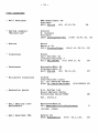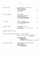
1
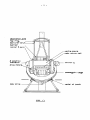
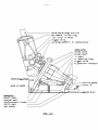
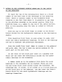
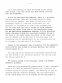
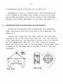
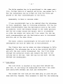
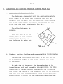
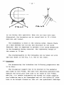
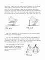
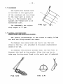
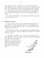
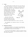
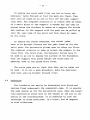
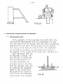
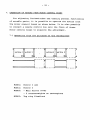
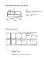
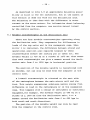
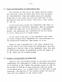
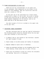
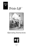
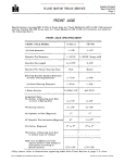
+ +E5 + o M Y 3.6m telescope MAINTENANCE MANUAL NUMBER 1 + lURE ING Edition nov.1976 R.Gri t t E'> t () 3.6m telescope MAINTENANCE MANUAL NUMBER 1 + lURE ING Edition nov.1976 R.Grip This manual deals only with the main structure. The figures are schematically shown. For detail studies of assemblies, consult Note ML 76-04: Reduced drawings for main structure. Other manuals will be issued as follows: No. Subject 2 Main gears 3 Mirrors, cells, covers and handling 4 Top units, carriages 5 Coude mirrors, sky baffle 6 Cabling, position controls, interlocks 7 Hydraulic plant, hydrostatic bearings 8 Alignment facilities 9 Aluminising plant 10 Prime focus area 11 Cassegrain area 12 Index - 1 - Content 1. Description of the different parts 2. Access to the different working platforms and to the inside of the structure 3. Dismounting and mounting procedure for the declination axis Tube structure - Mirror 4 assembly - Delta cable twist with position encoder - Mirror 3 arrangment Hydrostatic bearings - Centerpiece with counterweights and flexion bars - Lockdrive 4. Dismounting and mounting procedure for the polar axis Forks with declination shafts - Tie bars, working platform and counterweights for horseshoe Horseshoe - Cross beam - Lateral counterweight, cable twist and position encoder - Gearbox with drive - V-beam - Hydrostatic bearings - Lockdrive 5. Dismounting and mounting procedure for the pedestal Tail with north part and foot - South part Central tube - Mirror 5 assembly 6. Adjusting possibilities on pedestal North - south line - Declination angle to the horizon 7. Operation of motors from motor control boxes Operation from platform on centerpiece Operation from platform on polar axis - Operation from tail 8. Balancing possibilities Movable counterweights on delcination axis Fixed counterweights on declination axis - Movable counterweights on polar axis - Fixed counterweights on polar axis 9. 10. Obligatory yearly maintenance Spare parts - 2 - dec.lination .a,,·,s 'tcp rir\CO 5errurle.r 9rut -t barrie.r mirro.... ~ .arm c.en+re p·lece. main mirror c.e.ll cS pos.ih'on indic.aror mirror- 4 driv& mot-or r.adial oil pads lock. . drive. FIG. 1.1 - 3 - prima focua c:aq;p. and unit 6ky baFf'le. - OM top rinCO - on mirror :!I b.se o~d"':lve workinco pla+form on cenl'erp',e.ce. RoJa,. &K-is : horse. .hoe c,-o ss be:a m V - beAm N - b!!.ar'lnco r'lI'"\'b 0( Se.r- d"':, lie 0( POS'It-'lon indic:.at-ot- obser"in --r;,;.-:...-----, _. ~de~tal : south par-to c.eni-r.al part- reinForc.ement- +ubes north pariTa'l \ --J p,e.ce. FIG, 1.2., MOr~ oil ~ds mltTor 5 - 4 - 2. ACCESS TO THE DIFFERENT WORKING AREAS AND TO THE INSIDE OF THE STRUCTURE To reach the top of the centersection there is a fixed ladder on the west side of the telescope on the observing floor. There is another ladder on the horseshoe which connects to the fork from where it is possible to get down to the platform attached to the center section. From this platform there is a ladder to the top of the center section. This is only possible when the tube is locked in vertical position. From the top of the forks. there is access to the distribution blocks for the hydrostatic bearings on the declination shafts. From observing floor there is also access to alpha lockdrive and radial hydrostatic bearings. To work on the bearings one has to dismount the protection shieldings. From the coud~ floor level the~e is access to the pedestal and polar axis. One has to pass the narrow passage by the north part on the west side. On the front of the south part there is a gangway from which one can reach the distribution blocks for the hydrostatic bearings to the horseshoe. A ladder leads up to the pedestal from where the axial bearings to the horseshoe can be reached. There are also two man holes which allow access inside the horseshoe. The telescope has, of course, to be locked in 12 o'clock position. At the north part of the pedestal, one. can reach the distribution block for the north hydrostatic bearings and the bearings themselves. - 5 - It is also possible to enter the inside of the central tube through a man hole on the top. From inside the north foot can be reached. On the tie bars above the pedestal, there is a so-called mounting platform. There are two possibilities to reach there from the pedestal. One ladder continues up to the cross-beam. There is a man hole for entrance into the structure. It is possible to climb to the horseshoe and the two forks from this point. Inside the forks hydraulic pressure and return lines lead to the distribution blocks for the declination hydrostatic bearings. All the electrical cables also pass through the cross beam horseshoe and up to the forks to the center piece. The inside of the V-beam can also be reached from the man hole on the cross beam. The collecting tank for lubrification oil for the delta gear box is situated in the west part of the V-beam. Access to the cassegrain cage is possible from the observing floor with the tube locked in vertical position. See further service manual No 11. The top ring can be reached from the movable platform with the tube locked in the horizontal position. For the top units see service manual No 4. For general access to the telescope, there is a movable hydraulic platform. There are three manoevering possibilities. It has a reachable hight of 14 m and the extension platform has a stroke of 4 m rotating around the central support. The operation can only be executed from the extension platform. The two black buttons on the switch panel have to be pressed and the key pushed in - 6 - for operation. A green lamp indicates that the platform is operational. If the emergency stop has been pressed, one has to push the key in again. Up and down movements can just be done with the extension pl~tform retracted. NB. Before going up on the platform ensure that there is a stop shut in case of breakdown. - 3. 7 - DISMOUNTING AND MOUNTING PROCEDURE FOR THE DECLINATION AXIS 3.1 Tube structure The tube has to be lopked in horizontal position and replacement weight (fig 3.l)for top units has to be installed. The upper sky baffle must be dismounted. Disconnect all electrical cables. Now the telescope can be driven to vertical position. Lift the top ring with the 32 ton crane. The four ring fixation drives have to be operated at the same time. Place the top ring onto FIG. 3.1 the prepared carriage (fig. 3.2). The serrurier tubes are dismounted in pairs with the 5 ton crane. The barrier on the center section which serves as a counterweight can now be dismounted. The reassembly is done in reserve order. F'G. 3.2. - 8 - 3.2 Mirror 4 assembly Mirror 4 is mounted on the east fork. It can be lifted off with the 5 ton crane. Lifting eyes are located on the top. For levelling use small block and tackles. The cover has to be closed before dismounting. For further details see manual No 5. 3.3 Delta cable ·twist with position encoder All the inspection covers on the protection shield have to be dismounted first. The head of the position encoder on top of the protection shield has to be taken out with great care. All the cables for the delta cable twist have to be disconnected and placed inside the protection shield. Now the protection shield can be dismounted. Use a non metallic sling through the inspection holes. Be carefull to not touch the metallic band of the position encoder. The encoder drum can now be taken out with non metallic slings placed around the drum. For taking out the cable twist use the tool (fig. 3.3). Disconnect cables from center piece. The reassembly is done in reverse order. For further details of cable twist and position encoder, see manual No 6. FIG ~.3 - 9 - 3.4 Mirror 3 arrangment The sky baffle with its base can be lifted out as shown in fig. 3.4. Undo the six screws around the central hole on the base. If the main mirror is still in, the cover must be closed. "" , I I FIG. ~.4- FIG. 3.5 Mirror 3 assembly can be dismounted as shown in fig. 3.5. Mechanical interlock has to be suppressed and then one can operate the fingers. Mirror 3 arm can be dismounted now without any difficulties. If mirror 3 arrangment has to be mounted and dismounted when serrurier tubes and top ring are mounted adopt the following procedure. The sky baffle with its base can be dismounted with a special tool for that purpose. See fig. 3.6. The declination axis is than in the vertical position. For taking out the mirror 3 assembly the declination axis has to be in horizontal position. Use the tool (fig. 3.7) and screw FIG. 3.CO - 10 - on to the cell. Suppress the mechanical interlock and operate first the upper finger and then the lower finger. The arm can be lifted out through the serrurier tubes with the arm swung out to the center of declination axis. See fig. 3.8. The reassernbly is done in reverse order. For further information about mirror 3 arrangment, see manual No 5. FIG. 3.5 3.7 Hydrostatic bearings To work on the hydrostatic bearings it is possible to use the mobile platform or the small platform which can be fixed to the fork. See fig. 3.9. Between the forks there is a preload of 80 ton which has to be released before dismounting the bearings. If just one bearing has to be taken out, it is not necessary to release this preload because the load can be taken by the other. - 11 - I :zJ ~ \ FIG. ~.IO FIG. 3.9 First the two covers over the joints have to be dismounted. Than release the load with the big screws. Be sure to undo the screw which blocks the big screw first. Now the pad support can be dismounted while keeping the pad in place. Normally it is possible to lift the pads out without tools, but if necessary a tool is available, see fig. 3.10. If all the pads have to be dismounted first, one has to bring the three jacks forward against each declination shaft. There are two mechanical and one hydraulic jacks. The two mechanical ones can be reached from outside the fork. The hydraulic jack operates with the pump on top of the fork. The 2 pressure should be 200 kp/cm • The pre10ading devices "ydr~lic jack r -'-- . lOOT on each fork have than to be c~ dismounted. See fig. 3.11. Release the load on the pads by advancing the big jacks. I MC~6L..rf:-...IL...,}! It is then possible to undo I the big screw on each pad. I -~ I I I -"t.:..-~ After this procedure the pre10ading devices have to I Flu. 3.11 - 12 - be dismounted and all the pads can be taken out. Reassembly is done in reverse order. The centerpiece has to be aligned 50 mm offset from center of polar axis. This can be done by pushing with the big jacks in the preloading devices. For further adjustment of the pads, see manual No 7. 3.6 Centerpiece with counterweights and flexionbars Before the centerpiece can be dismounted the cassegrain cage, main mirror cell and cover have to be dismounted. See manual No 3. Connect two slings onto the south side and two block and tackles 10 ton on the north side. See fig. 3.12. The lock has to be retracted now. The declination shafts have to be retracted and immobilised •. See fig. 3.13. Use a cross of U-beams above the hole of the fork to fix the shafts. Three small feet to screw on to the shaft and so prevent it from tilting are available. I " I I , _ ~ ~ • I 8 I _+- __ . , ', !i --l--._. ' ' I I FIG. 3.1~ - 13 - The delta gearbox has to be positioned in the upper position. Further details of gearbox and drive, see manual No 2. Now the centerpiece can be lifted out from the forks and placed on the four counterweights on the floor. Reassemb1y is done in reverse order. If one counterweight has to be removed when the telescope is fully assembled. Keep to following procedure. For the two south counterweights take the declination axis as far north as possible. Drive the movable weight to the lower position and fix two slings around the weight. Now it is possible to slide the weight out using the 5 ton crane. For the two north counterweights put the declination axis in horizontal position and do the same thing. The small lateral counterweight on the east side of the centerpiece can also be taken out in this position. The f1exion bars can be taken out when telescope is fully assembled. The telescope has to be in the vertical position and with the main mirror dismounted. Use the 5 ton crane through the serrurier struts and connect the hook to the lifting eye on the bar. Undo the big nut and sink the bar through the centerpiece. 3.7 Lock drive The lock drive is mounted on the west fork behind the gear box. It can easily be dismounted with the 5 ton crane hook going down between the fork and centerpiece. The thread for the lock pin has some play to give the pin some mobility freedom. This movement is used for the balancing - 14 - of the tube. According to in which direction the pin has the force, a micro switch is activated and prevents the lock pin from coming out. At issue date this doesn't work very well because the weight of the pin itself activates one switch and blocks the movement of the telescope. This function is now bridged in the interlock chain to allow the operation o~ the telescope. The lockdrive can lock the declination axis in three different positions: vertical, south and horizontal. Corresponding holes are at the counterweights and on the cassegrain cage for the south position. - 15 - 4. DISMOUNTING AND MOUNTING PROCEDURE FOR THE POLAR AXIS 4.1 Forks with declination shafts The forks are dismounted with the declination shafts still fixed in the hole. Pay attention that the two location pins for each fork are taken out first. Using the 32 ton crane place two blocks and tackles and one sling over the hook, as shown in fig. 4.1. The alpha lock must be engaged. Once the fork is on the floor, tilt it with the outside facing upwards. Now the shaft can be taken out. FIG. 4.1 4.2 Tiebars, working platform and counterweights for horseshoe The working platform is difficult to get out and in. It is possible to get it out either towards the south or the north. To take the tie bars out, the horseshoe has to be turned to one side and locked in this position. For this operation fix cables on both ends tops of the horseshoe and follow the radius of the horseshoe down to the pedestal. See fig. 4.2. Pull with mechanism fixed on the pedestal. Naturally the oi1p1ant for the hydrostatic bearings has - 16 - FIG. 4.3 to run during this operation. When the tie bars have been dismounted, the horseshoe can be turned back to 12 o'clock position and locked. The reassembly is done in the reverse order. Ensure there is a shim between the tie bar and structure at the north fixation. This is important to prevent a too large deflection in the horseshoe during rotation. The tightening torque of the screws is 70 kpm. The counterweights on the horseshoe can be taken out with the tool shown in the fig. 4.3. Use 32 ton crane. 4.3 Horseshoe For dismounting the horseshoe the following preparation has to be done. The triangular support has to be mounted on the pedestal ~nd fixed to the V-beam. Two bars with adjusting possibilities against the north part have also to be fixed on the V-beam. See fig. 4.4. Before tightening the screws for these supports the lockdrive has to be disengaged and all the hydraulic jacks have to be brought forward so that all the hydrostatic bearings - 17 - are free. There are two jacks actin~ radially on the horse- shoe close to the bearings. Two more jacks are acting axially on the horseshoe. There is one jack on the north acting on the north bearing ring between the two hydrostatic bearings. After this the two cross beam supporting legs can be mounted and the feet adjusted for the floor, see fig. 4.5. FIG. 4·4 FIG. 4·5 The last operation is the mounting of the filling piece on the top of the horseshoe. To lift the horseshoe out fix two blocks and tackles to the filling piece and two slings to the lower part of the horseshoe. See fig. 4.6. There are two location pins against the crossbeam which have to be taken out first. The reassembly is done in the reverse order. The pressure and return lines for oil inside the structure should be installed. FIG. 4.<0 - 18 - 4.4 Crossbeam Two blocks and tackles have to be fixed to the upper part of the crossbeam and two slings to the lower part as shown in fig. 4.7. Two location pins against the V-beam have to be dismounted first. For reassembly the tighte- FIG. 4.7 ning torque is 70 kpm. 4.5 Lateral counterweight Cable twist and position encoder. The lateral counterweight on the V-beam is simply lifted out with two slings around the tubes. To dismount the cable twist one has to use the tool shown in the fig. 4.8. attached to the small counter lever crane of 12 ton. To dismount the position encoder drum, one has first to dismount the head to the encoder. After that one has to take away the top-cover fixed to the north part of pedestal FIG. 4..~ - 19 - which serves also as a support for the encoder head. The drum support for the cables from the tail and the drum cover have to be dismounted. The cover is divided into two parts. A "T" shape tool can be used to dismount the drum. See fig. 4.9. This operation must be done with the 12 ton counter lever crane. Take care not to touch the encoders metallic strip. For further information about position encoder and cable twist see manual no 6. 4.6 Gearbox with drive First the cover and oil sump between the north part of the pedestal and the geardrive have to be dismounted. The gallery on the observing floor has to be taken away before dismounting the drive. The reaction arm has to be dismounted and gearbox turned to the top. There it can be lifted off with the 12 ton counterlever crane. To dismount the drive, put a sling in the hole of the gear wheel and lift with crane. Use small blocks and tackles for taking the inclination. See fig. 4.10. Fix a bar across the lower part of the drive. For further information about geardrive and reaction arm, see manual no 2. FIG. 4.10 - 4.7 20 - V-beam The V-beam cannot be lifted with the 32 ton crane as the center of grav~ty of this part is outside the range of the crane. Therefore a transversal beam between the 32 ton crane and the 12 ton counter lever crane has to be used. See fig. 4.11. The triangular support underneath the V-beam has to be unscrewed from the pedestal but can be fixed to the V-beam. The supporting legs on the front must be brought up and fixed underneath the V-beam. With the V-beam lying horizontally on the floor, FIG. 4. 11 it can be divided into several parts. The north bearing ring on one side and then the two legs of the beam. For reassernbly the tightening torque of the screws is 70 kpm. 4.8 Hydrostatic bearings There was no problem in the mounting and dismounting of tl\le b'eari'n9's" tiuring' th'e preassembly because they were l ' mounted before the polar axis was placed. No tools have been destgned to remove the bearing whilst the polar axis is mounted. The following procedure is therefore purely theoretical. - 21 - To remove the axial pads first one has to bring the hydraulic jacks forward so that the pads are freed. They must also be fixed so as not to fall off the ball supporting them. The simplest solution is to attach them by means of a metal plate to the support. A wooden bar can then be placed above the tie-bars to serve as a support for blocks and tackles. So the support with the pads can be pulled up onto the last step of the stair and from there be taken by the crane. To remove the radial bearings, th~ radial jacks have to be brought forward and the pads fixed as for the axial pads. The protection plates must be taken out first. The simplest solution is than to attach the support to the crane from the front side. Non-metallic slings have to be used so as not to damage the surface of the horseshoe. Sink the support with paces behind the south part of pedestal down to the coude floor level. The north pads are so light that they can be taken out by hand. It is not a easy procedure. Here the hydraulic jack must also be brought forward first. 4.9 Lockdrive The lockdrive can easily be dismounted with block and tackles fixed underneath the cassegrain cage. It is exactly the same design as for the declination axis. Here the balancing possibility works well as the weight of the pin is not acting on the microswitches. It is possible to lock the telescope in three positions: 12 o'clock, and 90' degrees in both directions. - 22 - 5. DISMOUNTING AND MOUNTING PROCEDURE FOR PEDESTAL 5.1 Tail with north part and foot The tail is the first piece to be placed onto the coude floor. The walking gallery around the north area has to be dismounted. Then the north part is assembled to the tail and the whole correctly positioned as in fig. 5.1. Before that the base plate for the foot must be fixed. The pieces for the foot are placed near to the hole in the north part. The foot is positioned when the central tube is assembled to the north part. There is a lifting eye in the top of the central tube for fixation of block and tackels. 5.2 South part The two parts of the south part are first assembled together in the upright position as in fig. 5.2. There are two location pins to be fixed. The tightening torque of bolts is 70 kpm. FIG. 5.2. - 23 - 5.3 Central tube The central tube is fixed to the south part as shown in fig. 5.3. After tightening of all screws (70 kpm) the north end is lowered and assembled to the north part. The reenforcement bars are then positioned between the south part and the central tube. The two south feet are then positioned with a small block and tackle fixed in a simple ladder formation. See fig. 5.4. FIG.5.4 FIG. 5:~ 5.4 Mirror 5 assembly Mirror 5 assembly has to be dismounted with the counter lever crane. It can be lifted out as a complete assembly as in fig. 5.5. For storing there is a special stand which consists of a tube with two legs. See fig. 5.5. For further information about mirror 5 see manual No 5. - 24 - FIG 5.5 FIG 5.6 6. ADJUSTING POSSIBILITIES ON PEDESTAL 6.1 North-south line At the assembly of the telescope the north-south line was given by measurements from the astronomers. On that line the north foot was placed. This foot has no adjusting possibilities side ways. The south part can be shifted side ways ± 29 mm from the nominal axis. The adjustment can be done by releasing and tightening the screws on the support in the center of the south part. See fig. 6.1. Each individual foot can be adjusted in height. For this one has to unload the foot by positioning a 50 ton jack underneath the structure near to the foot. Then the internal screw can be turned by the hexagonal shaft on top of the foot. --- The pitch of the screw is 2 mm. First the earthquake screws have to be released. FIG 6.1 - 25 - 7. OPERATION OF MOTORS FROM MOTOR CONTROL BOXES For adjusting limitswitches and testing general functioning of movable parts, it is possible to operate the motors from the motor control boxes as shown below. It is also possible to connect a remote control box onto the front of these motor control boxes to simplify the adjustment. 7.1 Operation from the platform on the centerpiece ---L.r'-----",.,.- - - - b ..r---_.r-----..,.. - - - - I I MCBCl I I -~ 1:,=======::::::::,r - - I I c:::::=======~L "\.J"" - n I I I : Ft. MCBH1: Mirror 3 arm MCBC1: MCBH2: Mirror 3 - Main mirror cover MCBH3 : - - -, I I I L J 5 counterweights on centerpiece Top ring fixations r - - -"b ::1===::::::1 I I I I .P - 26 - 7.2 Operation from platform on polar axis MCBM1: - Mirror 4 alignment drives - Mirror 4 cover - Polar counterweight --- - Delta lock -- 7.3 Operation from tail MCBF1: - Alpha lock - Mirror 5 arm Mirror 5 cover - Tube lock in horizontal position - 27 - 8. BALANCING POSS IBILI TIES Fig. 8.1 and 8.2 show s the situa tion of all the coun terw eight s on the main struc ture . FIG. e.1 movAb le latera l c.ou..,terwe.i~t 2.=-00 on polar ,;ax'15 k.ctJ h---- ..,... M-ft t......- - movab le c.ounl'erwe.'I'tS''" en c:.e.ntre. ?Iec.e C2lO0k ..:Q FIG.. ·e,.a - 28 - As described in note 3.8 an approximate balancing possibility is built in the two lockdrives. But at the moment of this edition it does not work for the declination axis. The balancing is then done with the difference in motor current on the servo motors. For information about balancing controlled from the computer, see service manual issued by the control section. 8.1 Movable counterweights on the declination axis There are four movable counterweights operating along the declination axis. They compensate for differences in loads of the top units and in the cassegrain cage. When mirror 3 is installed, the difference between stored and operational position also requires balance by these counterweights before the locking pin is taken out. The movable weight is 750 kg on a stroke of 1675 mm. That means that each counterweight can give a moment around the declination axis from 0 to 1250 kpm in horizontal position. The position of the movable weights is registrated with an encoder, but can only be read from the computer in the control room. A lateral counterweight is situated on the east side of the centerpiece between the main mirror cell and the fork. This weight compensates unbalance mainly coming from difference in load on the centerpiece or in the cassegrain cage. This happens with a change of instrument or electronic equipment for example. The movable weight is 600 kg on a • stroke of 1000 mm from the declination axis, i.e. a ± moment around the declination axis from 0 to 600 kpm in both south and north directions. The position of the movable weight can only be read from the computer in the control room. - 29 - 8.2 Fixed counterweights on declination axis The barriers on the top of the center section around the serrurier struts are made from solid iron and serve as counterweights. They were added during the assembly stage when it was found out that the lower part of the declination axis was too heavy. They have a total weight of 1700 kg. In the north part inside the cassegrain cage there is a compartment for electronic equipment. When no equipment is there the space has to be filled with a replacement weight. The dimensions are l75x500x30 mm and the weight is 20 kg. There are 20 of these plates. On the outer south part of the cassegrain cage there are steel weights which compensate for load difference in the south-north direction. Each weight is 20 kg. There is also a possibility to fix small weights onto the top ring on the side facing the centerpiece. This will compensate a heavier load in the cassegrain cage. The size of these steel plates is 250x425x12 mm and the weight is 10 kg. There are 20 of these plates. 8.3 Movable counterweight on polar axis There is only one movable weight on the polar axis which compensates for difference of loads in east-west direction. It is mounted on the V-beam. The movable weight is 2500 kg. The stroke is 1000 mm in each direction from the center of the polar axis, i.e. a moment from 0 to 2500 kpm in each direction. The position of the movable weight can only be read from the computer in the control room. - 30 - 8.4 Fixed counterweights on polar axis There are two big counterweights on the upper part of the horseshoe. They compensate for the weight of the opening in the horseshoe. They are filled with lead and each has a weight of 7500 kg. On the east leg of the cross-beam are 6 steel plates screwed with a weight of 350 kg each. One plate is welded on the outer side and has an additional weight of 350 kg. These weights compensate for the heavier load on the west side due to the declination drive. One small weight of 100 kg is welded on the upper side of the east fork. 9. OBLIGATORY YEARLY MAINTENANCE The main structure does not need any special maintenance. The following points should be checked during the one week shut down foreseen in June every year. 1. A general look at the outside of the structure. Tighten all small screws if loose. 2. Check torque in big M24 screws and tighten if necessary. 3. Repaint damage of paint work if necessary. 4. Check the machined surfaces on the horseshoe and on the north bearing. Clean around the oil pads if dirty. 5. Check that the hydraulic jacks for lifting the horseshoe are working. Top up oil if necessary. - 31 - 6. Clean inside the structure and if any oil leaks are found, locate and repair. 7. Check all the micro switches by pushing the buttons for each motor, driving to the end positions. Check for any disfunctioning of mechanical parts in between. 8. Check the top ring exchange. 10. SPARE PARTS 1. Top ring fixation drives E~~~~~~~~~_~~~_~~e~ No. - ball bea,rings - spring washers - motors 4 ~ 90/140x24 192 ~ 25/12.2 x 0.9 4 DK 5406/143 SKF 6018 Belleville Bauer 2. Counterweights parallel to optical axis in the centerpiece ~ 12/37 x 12 SKF 6301 8 ~ 25/62 x 7 SKF 7305 B/UO - ball bearings 4 ~ 40/80 x 18 SKF 6208 2RSl - couplings 4 Junior 14 - couplings 8 M24 - gear boxes 4 L 240 1 d - miniature couplings 4 Oldham coupling Split Hub Type P.I.C. No T8-9 Dim A = 0.1875 and clamps Ll-5 - reduction gear 4 1:30 - motors 4 DK 5406/143 with brake Baur - ball bearing nut with spindle screw 4 26. 2,2. 50 Mannesmann - ball bearings 48 - ball bearings - spring washers 160 ~ Bowex Bowex Normzahndider Muffet MC 5397-1 31.5/16.3 x 1,75 Belleville -:.32 - 3. Lateral counterweight - ball bearings 2 ~ - ball bearing 1 INA PNO - gear box 1 L 240 1 d - miniature coupling 1 Oldham coupling Split Hub Type P.I.C. No T8-9 Dim A = 0.1875 and clamps Ll-5 - reduction gear 1 1:3 - motor 1 OK 5406/143 with brake Bauer - coupling 1 Junior 14 - coupling 2 M 24 - ball screw with spindle 1 Rotax G37.10.2400.Y - spring washers 6 ~ - roller guide 4 Technometal No PA 6100 - roller rail 2 Technometa1 No R6 L=2850 25/52 x 15 ~ SKF 7205 BG 20/42 Normzahnrader Muffet MC 5397-1 Bowex Bowex 25/12,2 x 1,5 Belleville 4. Fork prong - bellows on return line for oil pads 48 Hydra 3181 l5hE6 - O-ring ~ 6 mm 2 ~ ext. 945 mm, shore 50 - O-ring ~ 6 mm 2 ~ ext. 1080 mm, shore 50 - O-ring ~ 6 mm 2 ~ ext. 1330 mm, shore 50 - O-ring ~ 6 mm 2 ~ ext. 1420 mm, shore 50 4 Simrit GWBM 1270 x 1310 x 18 Profil nr. 1 - ball bearings 4 ~ - motors 2 OK 5406/143 - joint 5. Lock drives 110/170 x 28 SKF 6022 Bauer - 33 - 6. Lateral counterweight on polar axis No. Q!~~~~!~~~_~~~_~~E~ - ball bearing nut with spindle 1 Mannesmann 26.2.1.70 - ball bearing 2 l2S 10/35 x 11 SKF 6300 2RS - ball bearing 2 l2S 20/52 x 15 SKF 6304 2RSl - ball bearing 1 l2S 50/110 x 27 SKF 1310 - ball bearing 2 l2S 65/120 x 23 SKF 7213 BG coupling 1 Bowex junior 14 - coupling 1 Bowex M 24 - motor 1 DK 7407/178 with breake Bauer - spring washers 8 l2S - roller guide 8 Rotax RZA 5002 - roller rail 2 Technometal B2 L=2800 mm - 1 Technometal C2 L=2800 mm - metallic bellows 2 Hydra AF 1814 - metallic bellows 2 Hydra AF 1407 - rubber bellows 2 S.Flex 6 GE 140 DO-2RS INA roller rail 31,5/16,3 x 1,75 Belleville 7. Others - hydraulic jacks for horseshoe - hydraulic jack for north bearing ring - ball bearings for oil pad supports - 34 - FIRM ADDRESSES - Ball bearings - Spring washers "Belleville" - Motors - Couplings - Gearboxes - Miniature couplings - Reduction gears SKF-Kuge11ager AG Postfach 8021 Zurich (01) 47.03.70. Schnorr W. Gutmann Postfach 3800 Inter1aken-Ost Bauer Meier & Co 5013 Niedergosgen CH (036) 22.41.21. CH (064) 41.23.15. CH Bowex Carl Geisser AG Industriestrasse 7 8117 Fa11anden (01) 825 11 61 CH Normzahnrader AG F1ue1astrasse 47 8047 Zurich (01) 52.41.10. CH 01dham Jean-Charles Ciana 33, rue Abraham Robert 2300 La Chaux-de-Fonds (039)36265 CH S.H. Muffet Ltd Mount Ephraim Works Turnbridge Wells-KENT GB Tel. 20231. 2 - Ball bearing nuts Mannesmann Maschinenfabrik 563 Remscheid-b1iedinghausen D (02123) 47046 - Ball bearings INA Hydre1 AG 8590 Romanshorn (071) 63.11.91. CH - 35 - - Ball screw Rotax precision products Mayland Avenue Hemel Hempstead Hertfordshire GB Tel 2233 - roller guides Technometal 20, avenue de Rosny Boite postale 25 93 Neuilly-Plaisance F Tel. Paris 927.99.00. - O-rings Angst & Pfister 1219 Le Lignon-Geneve CH Tel. 96.42.11. - Joint Sinrit SKF-Kugellager AG Postfach 8021 Zurich (01) 47.03.70. CH - Rubber bellows S.Flex - Metallic and rubber bellows S. Flex Hydra Metallschlang Fabrik Pforzheim Vorm Hch Witzenmann Gmbh 7530 Pforzheim o Postfach 1280 Ostliche Karl-Friedrich Str. 134 - Hydraulic jacks Societe Savoisienne de verins hydrauliques Botte postale 57 73200 Albertville F