1
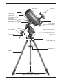
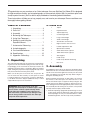
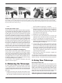
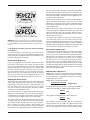
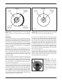
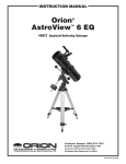
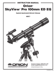
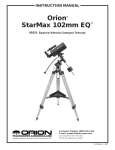
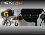
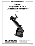
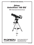
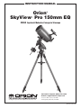
instruction Manual Orion SkyView Pro 150mm EQ ® ™ #9968 Equatorial Maksutov-Cassegrain Telescope Customer Support (800)‑676-1343 E-mail: [email protected] Corporate Offices (831)‑763-7000 Providing Exceptional Consumer Optical Products Since 1975 89 Hangar Way, Watsonville, CA 95076 IN 258 Rev. B 01/09 Optical tube Finder scope Finder scope bracket Declination lock lever (opposite‑side) Right ascension lock lever (opposite‑side) Declination slow-motion control knob Safety thumbscrew Eyepiece Mounting plate securing knob Star diagonal Focus knob (not shown) Counterweight shaft Right ascension slow-motion control knob Counterweights Right ascension axis rear‑cover Counterweight lock knobs Latitude scale Latitude adjustment L-bolts Center support shaft Tripod support tray Tripod leg Leg lock‑knobs Figure 1. The SkyView Pro 150mm EQ. 2 Congratulations on your purchase of an Orion telescope. Your new SkyView Pro 150mm EQ is designed for high-resolution viewing, and astrophotography of astronomical objects. With its precision optics and sturdy equatorial mount, you’ll be able to enjoy hundreds of fascinating celestial denizens. These instructions will help you set up, properly use, and care for your telescope. Please read them over thoroughly before getting started. Table of Contents 2. Parts List 1. Unpacking . . . . . . . . . . . . . . . . . . . . . . . 3 1 Tripod 2. Parts List . . . . . . . . . . . . . . . . . . . . . . . . 3 1 Equatorial mount 3. Assembly . . . . . . . . . . . . . . . . . . . . . . . . 3 1 Tripod support tray 4. Balancing the Telescope . . . . . . . . . . . . 5 1 Counterweight shaft 5. Using Your Telescope . . . . . . . . . . . . . . . 5 1 Large counterweight 1 Small counterweight 2 Slow-motion control knobs 1 Right ascension axis rear cover 6. Setting Up and Using the Equatorial Mount . . . . . . . . . . . . . . . . . . 7 7. Astronomical Observing . . . . . . . . . . . 11 1 Latitude adjustment L-bolt 8. Astrophotography . . . . . . . . . . . . . . . . . 14 1 Optical tube assembly 9. Care and Maintenance . . . . . . . . . . . . 14 1 25mm Sirius Plössl eyepiece 10. Specifications . . . . . . . . . . . . . . . . . . . . 15 1 10mm Sirius Plössl eyepiece 11. Appendix: Collimating . . . . . . . . . . . . . . 16 1 Star diagonal 1 Finder scope 1 Finder scope bracket with O-ring 1 Dust cover 1. Unpacking The entire telescope will arrive in one box. Be careful unpack‑ ing the box. We recommend keeping the box and all origi‑ nal packaging. In the event that the telescope needs to be shipped to another location, or returned to Orion for warranty repair, having the proper box and packaging will help ensure that your mount will survive the journey intact. Make sure all the parts in the Parts List are present. Be sure to check each box carefully, as some parts are small. If anything appears to be missing or broken, immediate‑ ly call Orion Customer Support (800-676-1343) or email [email protected] for assistance. Warning: Never look directly at the Sun through your telescope or its finder scope—even for an instant—without a professionally made solar filter that completely covers the front of the instrument, or permanent eye damage could result. Young children should use this telescope only with adult supervision. 3. Assembly Assembling the telescope for the first time should take about 30 minutes. No tools are needed other than the ones provid‑ ed. All screws should be tightened securely, but be careful not to over-tighten or the threads may strip. Refer to Figure 1 during the assembly process. During assembly (and anytime, for that matter), do not touch the surfaces of the telescope’s front meniscus lens or the lenses of the finder scope or eyepieces with your fingers. The optical surfaces have delicate coatings on them that can eas‑ ily be damaged if touched inappropriately. Never remove any lens assembly from its housing for any reason, or the product warranty and return policy will be voided. 1. Stand the tripod legs upright and spread the legs out as far as they will go. Keep the tripod legs at their shortest (fully retracted) length, for now; you can extend them to a more desirable length later, after the scope is fully assembled. 3 Finder scope bracket Nylon alignment thumbscrews Finder scope Azimuth adjustment knobs Post Tensioner Figure 2. Orient the equatorial mount so that the post on the tripod head lines up between the azimuth adjustment knobs on the equatorial mount. 2. Place the base of the equatorial mount into the tripod head. Orient the equatorial mount so that the post on the tripod head lines up between the azimuth adjustment knobs on the equatorial mount (Figure 2). You may need to loosen the azimuth adjustment knobs on the equatorial mount in order to fit the mount onto the tripod head. Focus lock ring Figure 3a. The 8x40 finder scope. 3. Thread the central support shaft into the equatorial mount until tight. This will secure the equatorial mount to the tri‑ pod head. 4. Remove the knob and washer from the bottom of the cen‑ ter support shaft. Slide the tripod support tray up the bot‑ tom of the central support shaft until the three tray arms are touching the legs of the tripod. The flat side of the accessory tray should be facing up. Make sure the “V” of each tray arm is against a tripod leg. Place the washer back on the center support shaft against the tray, and thread the securing knob all the way up the center support shaft until it is tight against the tray. The tripod support tray provides additional stability for the tripod, and holds five 1.25" eyepieces and two 2" eyepieces. 5. Thread the latitude adjustment L-bolt into the rear of the equatorial mount as show in Figure 1. 6. Thread the counterweight shaft into the equatorial mount at the base of the declination axis until tight. Make sure the casting at the top of the counterweight shaft is threaded clockwise as far as it will go before attaching the shaft. Once the shaft is installed, turn the casting counter-clock‑ wise until the top of the casting is flush with the mount. 7. Remove the knurled “toe saver” retaining screw on the bottom of the counterweight shaft and slide both counter‑ weights onto the shaft. Make sure the counterweight lock knobs are adequately loosened to allow the counterweight shaft to pass through the hole. Position the counterweights about halfway up the shaft and tighten the lock knobs. Replace the toe saver at the end of the bar. The toe saver 4 Figure 3b. Pull‑back on the tensioner and slide the finder scope into its bracket until the O-ring is seated in the bracket ring. prevents the counterweights from falling on your foot if the lock knobs happen to come loose. 8. Attach the slow-motion control knobs to the right ascen‑ sion and declination worm gear shafts of the equatorial mount by sliding them onto the shaft. Line up the flat on the end of the shaft with the corresponding feature on the interior of the knob. The knobs can be attached to either end of the shafts; use whichever end is most convenient. 9. Loosen the black mounting plate securing knob as well as the metal safety thumbscrew on the top of the equato‑ rial mount. Place the optical tube’s mounting plate in the dovetail slot so that it is positioned midway in the dovetail slot. Tighten the mounting plate securing knob and safety thumbscrew to secure the optical tube. Figure 4a-d. Proper operation of the equatorial mount requires that the telescope tube be balanced on both the right ascension and Declination axes. (a) With the R.A. lock lever released, slide the counterweights along the counterweight shaft until it just counterbalances the tube. (b) When you let go with both hands, the tube should not drift up or down. (c) With the Dec. lock knob released, loosen the mounting plate securing knob and safety thumbscrew a few turns and slide the telescope forward or backward. (d) When the tube is balanced about the Dec. axis, it will not move when you let go. 10. Place the right ascension rear axis cover on the equatorial mount. Installing the Finder Scope To place the finder scope (Figure 3a) in the finder scope brack‑ et, unthread the two black nylon thumbscrews until the screw ends are flush with the inside diameter of the bracket. Place the O-ring that comes on the base of the bracket over the body of the finder scope until it seats into the slot on the middle of the finder scope. Slide the eyepiece end (narrow end) of the finder scope into the end of the bracket’s cylinder opposite the adjustment screws while pulling the chrome, spring-loaded tensioner on the bracket with your fingers (Figure 3b). Push the finder scope through the bracket until the O-ring seats just inside the front opening of the bracket cylinder. Release the tensioner and tighten the two black nylon thumbscrews a couple of turns each to secure the finder scope in place. Insert the base of the finder scope bracket into the dovetail holder on the top of the focuser. Lock the bracket into position by tightening the knurled thumbscrew on the dovetail holder. Inserting the Star Diagonal and Eyepiece Remove the dust cap from the eyepiece adapter and insert the chrome barrel of the star diagonal into the eyepiece adapter and secure it with the thumbscrews. Remove the dust cap from the star diagonal and insert the 25mm Plössl eyepiece into the star diagonal and secure it in place with the thumbscrews on the diagonal. (Always loosen the thumbscrews before rotating or removing the diagonal or an eyepiece.) the right ascension axis. Rotate it until the counterweight shaft is parallel to the ground (i.e., horizontal) 2. Now loosen the counterweight lock knobs and slide the weights along the shaft until they exactly counterbalance the telescope (Figure 4a). That’s the point at which the shaft remains horizontal even when you let go of the tele‑ scope with both hands (Figure 4b). 3. Retighten the counterweight lock lever. 4. Loosen the metal safety thumbscrew on the top of the equatorial mount. Then with one hand on the optical tube, loosen the mounting plate securing knob (Figure 4c). 5. Slide the optical tube into the dovetail slot until the mount‑ ing plate is positioned midway in the dovetail slot. Retighten the mounting plate securing knob. 6. Loosen the Dec. lock lever and test the balance of the opti‑ cal tube by letting go with both hands. If the optical tube does not move in either direction (Figure 4d) then the tube is balanced in declination. If the optical tube does move, then retighten the Dec. lock lever and repeat from step 4 above, this time sliding the optical tube to a new position and testing the balance again. 7. When the tube is balanced in declination, retighten the metal safety thumbscrew. The telescope is now balanced in both axes. When you loos‑ en the lock lever on one or both axes of motion and manually point the telescope, it should not drift from where you point it. Your telescope is now completely assembled and should appear as shown in Figure 1. 5. Using Your Telescope 4.Balancing the Telescope Focusing the Telescope With the 25mm eyepiece inserted in the star diagonal, move the telescope so the front (open) end is pointing in the general direction of an object at least 1/4-mile away. Now, with your fingers, slowly rotate the focus knob until the object comes into sharp focus. Go a little bit beyond sharp focus until the image just starts to blur again, then reverse the rotation of the knob, just to make sure you’ve hit the exact focus point. To ensure smooth movement of the telescope on both axes of the equatorial mount, it is imperative that the optical tube is properly balanced. We will first balance the telescope with respect to the right ascension (R.A.) axis, then the declination (Dec.) axis. 1. Keeping one hand on the telescope optical tube, loosen the R.A. lock lever. Make sure the Dec. lock lever is locked. The telescope should now be able to rotate freely about NOTE: The image in the telescope will appear reversed from left to right. This is normal for telescopes that utilize 5 Turn the focus knob until the object is properly focused. Make sure to position the object in the center of the telescope’s eye‑ piece by turning the R.A. and declination slow-motion control knobs (the R.A. and Dec. lock levers must be tightened to use the slow-motion control knobs). View through finder scope Now look in the finder scope. Is the object visible? Ideally it will be somewhere in the field of view. If not, some coarse adjustment to the finder scope bracket’s alignment thumb‑ screws will be needed until the object comes into the finder scope’s field of view. With the image in the finder scope’s field of view, you now need to fine-adjust the alignment thumbscrews to center the object on the intersection of the crosshairs. Adjust the aim of the finder scope by turning the thumbscrews, one at a time, until the object is centered. View through the SkyView Pro 150mm EQ Figure 5. Images through the finder scope will appear upsidedown and backwards (rotated 180°). Images through the SkyView Pro 150mm EQ with its diagonal in place will be reversed from leftto right. a star diagonal. The finder scope view will be rotated 180° (see Figure 5). If you have trouble focusing, rotate the focus knob counterclockwise as far as it will go. Look through the eyepiece while slowly rotating the focus knob clockwise. You should soon see the point at which focus is reached. Viewing with Eyeglasses If you wear eyeglasses, you may able to keep them on while you observe, if the eyepiece has enough “eye relief” to allow you to see the whole field of view. You can try this by looking through the eyepiece first with your glasses on, and then with them off, and see if the glasses restrict the view to only a por‑ tion of the full field. If they do, you can easily observe with your glasses off by just re-focusing the telescope by the needed amount. If you suffer from severe astigmatism, however, you may find images noticeably sharper with your glasses on. Aligning the Finder Scope The SkyView Pro 150mm EQ comes with a 8x40 achromatic finder scope (Figure 3a). The number 8 means eight-times magnification and the 40 indicates a 40mm diameter front lens. The finder scope makes it easier to locate the subject you want to observe in the telescope, because the finder scope has a much wider field of view. The finder scope uses a spring-loaded bracket that makes alignment of the finderscope very easy. As you turn either of the thumbscrews, the spring in the bracket’s tensioner moves in and out to keep the finder scope secure in the bracket. The finder scope must be aligned accurately with the tele‑ scope for proper use. To align it, first aim the main telescope at an object at least a 1/4 mile away—the top of a telephone pole, a chimney, etc. First, loosen the R.A. and Dec. lock levers and move the telescope until it is pointing towards the desired object. Then sight along the tube to aim the telescope. 6 The finder scope alignment needs to be checked before every observing session. This can easily be done at night, before viewing through the telescope. Choose any bright star or planet, center the object in telescope eyepiece, and then adjust the finder scope bracket’s alignment thumbscrews until the star or planet is centered on the finder’s crosshairs. Focusing the finder scope If, when you look through the finder scope, the images appear somewhat out of focus, you will need to refocus the finder scope for your eyes. Loosen the lock ring located behind the objective lens cell on the body of the finder scope (see Figure 3a). Back the lock ring off by a few turns, for now. Refocus the finder scope on a distant object by threading the objec‑ tive lens cell in or out of the finderscope body. Precise focus‑ ing will be achieved by focusing the finder scope on a bright star. Once the image appears sharp, retighten the locking ring behind the objective lens cell. The finder scope’s focus should not need to be adjusted again. Magnification & Eyepieces Magnification, or power, is determined by the focal length of the telescope and the focal length of the eyepiece. Therefore, by using eyepieces of different focal lengths, the resultant magnification can be varied. Magnification is calculated as follows: Telescope Focal Length Eyepiece Focal Length = Magnification The SkyView Pro 150mm EQ has a focal length of 1800mm, which when used with the supplied 25mm eyepiece yields: 1800mm 25mm = 72x The magnification provided by the 10mm eyepiece is: 1800mm 10mm = 180x The maximum attainable magnification for a telescope is directly related to how much light it can gather. The larger the aperture, the more magnification is possible. In general a fig‑ ure of 2x per millimeter of aperture is the maximum attain‑ Dec. slow-motion control knob Dec. lock lever Dec. setting‑circle Front opening A Ri (R scenght .A si .) on ax is R.A. slow-motion control knob Latitude scale n( De Latitude adjustment L-bolts tio cli na De R.A. lock lever Polar axis finder (optional) c.) ax is R.A. setting‑circle a. b. Figure 6a-b. The SkyView Pro 150mm EQ mount. able for most telescopes. Your SkyView Pro 150mm EQ has an aperture of 150 millimeters, so the maximum magnification would be about 300x. This level of magnification assumes you have ideal conditions for viewing. Keep in mind that as you increase magnification, the bright‑ ness of the object viewed will decrease; this is an inherent principle of the laws of physics and cannot be avoided. If mag‑ nification is doubled, an image appears four times dimmer. If magnification is tripled, image brightness is reduced by a factor of nine! Always start with your lowest power eyepiece and work your way up. Start by centering the object being viewed in the 25mm eyepiece. Then you may want to increase the magni‑ fication to get a closer view. If the object is off-center (i.e., it is near the edge of the field of view) you will lose it when you increase magnification since the field of view will be narrower with the higher-powered eyepiece. To change eyepieces, first loosen the securing thumbscrews on the diagonal. Then care‑ fully lift the eyepiece out of the holder. Do not tug or pull the eyepiece to the sides, as this will knock the telescope off its target. Replace the eyepiece with the new one by sliding it gently into the holder. Re-tighten the diagonal thumbscrews, and refocus for your new magnification. 6. Setting Up and Using the Equatorial Mount When you look at the night sky, you no doubt have noticed that the stars appear to move slowly from east to west over time. That apparent motion is caused by the Earth’s rotation (from west to east). An equatorial mount (Figure 6) is designed to compensate for that motion, allowing you to easily “track” the movement of astronomical objects, thereby keeping them Little Dipper (in Ursa Minor) Big Dipper (in Ursa Major) ter Poin Stars N.C.P. Polaris Cassiopeia Figure 7. To find Polaris in the night sky, look north and find the Big Dipper. Extend an imaginary line from the two "Pointer Stars" in the bowl of the Big Dipper. Go about five times the distance between those stars and you'll reach Polaris, which lies within 1° of the north celestial pole (NCP). from drifting out of your telescope’s field of view while you’re observing. This is accomplished by slowly rotating the telescope on its right ascension axis, using only the R.A. slow-motion knob. But first the R.A. axis of the mount must be aligned with the Earth’s rotational (polar) axis—a process called polar alignment. Polar Alignment For Northern Hemisphere observers, approximate polar align‑ ment is achieved by pointing the mount’s right ascension axis at the North Star, or Polaris. It lies within 1° of the north celes‑ tial pole (NCP), which is an extension of the Earth’s rotational axis out into space. Stars in the Northern Hemisphere appear to revolve around the NCP. To find Polaris in the sky, look north and locate the pattern of the Big Dipper (Figure 7). The two stars at the end of the “bowl” of the Big Dipper point right to Polaris. 7 Azimuth adjustment knobs Figure 8. For polar alignment, position the tripod so that the "N" label at the base of the mount faces north. The azimuth fine adjustment knobs above it are used to make small adjustments to the mount’s azimuth position. Be certain to loosen the tripod attachment knob on the central support shaft before adjusting these knobs. Observers in the Southern Hemisphere aren’t so fortunate to have a bright star so near the south celestial pole (SCP). The star Sigma Octantis lies about 1° from the SCP, but it is barely visible with the naked eye (magnitude 5.5). For general visual observation, an approximate polar align‑ ment is sufficient. 1. Level the equatorial mount by adjusting the length of the three tripod legs. 2. There are two latitude adjustment L-bolts (see Figure 6); loosen one while tightening the other. By doing this you will adjust the latitude of the mount. Continue adjusting the mount until the pointer on the latitude scale is set at the latitude of your observing site. If you don’t know your lati‑ tude, consult a geographical atlas to find it. For example, if your latitude is 35° North, set the pointer to 35. The lati‑ tude setting should not have to be adjusted again unless you move to a different viewing location some distance away. 3. Loosen the Dec. lock lever and rotate the telescope’s opti‑ cal tube until it is parallel with the right ascension axis, as it is in Figure 6. 4. Move the tripod so the telescope tube and right ascen‑ sion axis point roughly at Polaris. If you cannot see Polaris directly from your observing site, consult a compass and rotate the tripod so the telescope points north. There is a label bearing a large “N” at the base of the equatorial mount (Figure 8); it should be facing north. The equatorial mount is now polar aligned for casual observ‑ ing. More precise polar alignment is recommended for astro‑ photography. For this we suggest using the optional polar axis finder scope From this point on in your observing session, you should not make any further adjustments to the latitude of the mount, nor should you move the tripod. Doing so will undo the polar alignment. The telescope should be moved only about its R.A. and Dec. axes. 8 Eyepiece focus ring Alignment setscrews (3) Focus lock‑ring Objective lens Figure 9. The optional polar axis finder scope. Polar Alignment Using an Optional Polar Axis Finder Scope The SkyView Pro 150mm EQ mount can be equipped with an optional polar axis finder scope (Figure 9) which goes inside the right ascension axis of the mount. When properly aligned and used, it makes accurate polar alignment quick and easy to do. To install the polar axis finder scope, remove the cover at the rear of the mount’s right ascension axis (Figure 9) and thread the polar axis finder scope into the equatorial mount until tight. The reticle of the polar axis finder scope for the SkyView Pro has a tiny star map printed on it that makes precise polar alignment quick and easy. If you do not have a clear view of Polaris from your observing site, you will not be able to use the polar-axis finder to precisely polar align the telescope. To align the mount using the polar axis finder scope, follow these instructions: Alignment of the Polar Axis Finder Scope 1. Look through the polar finder at a distant object (during the day) and center it in the crosshairs. You may need to adjust the latitude adjustment L-bolts and the tripod posi‑ tion to do this. 2. Rotate the mount 180º about the R.A. axis. Again, it may be convenient to remove the counterweights and optical tube first. 3. Look through the polar finder again. Is the object being viewed still centered on the crosshairs? If it is, then no further adjustment is necessary. If not, then look through the polar finder while rotating the mount about the R.A. axis. You will notice that the object you have previously centered moves in a circular path. Use the three align‑ ment setscrews on the polar axis finder to redirect the crosshairs of the polar finder to the apparent center of this circular path. Repeat this procedure until the position that the crosshairs point to does not rotate off-center when the mount is rotated in R.A. Once this is accomplished, snug the setscrews so the alignment is secure. The polar axis finder scope is now ready to be used. When not in use, replace the plastic protective cover to prevent the “Polaris” on the finder’s reticle. You must first loosen the knob underneath the equatorial mount on the center sup‑ port shaft to use the azimuth adjustment knobs. Once Polaris is properly positioned within the reticle, you are precisely polar aligned. Retighten the knob underneath the equatorial mount. Note: From this point on in your observing session, you should not make any further adjustments in the azimuth or the latitude of the mount, nor should you move the tripod. Doing so will undo the polar alignment. The tele scope should be moved only about its right ascension and declination axes. Figure 10. The optical tube must be at a 90º angle to the right ascension axis in order to view through the polar axis finder. polar finder from getting bumped, which could knock it out of alignment. Using the Polar Axis Finder Scope 1. Approximately polar-align the mount as outlined in the procedure above. 2. Loosen the Dec. lock lever and rotate the optical tube on the declination axis so that the tube is at a 90° to the right ascension axis (Figure 10). Tighten the Dec. lock lever. 3. Remove the cap on the front of the equatorial mount (Figure 6). Focus the polar finder by rotating the eyepiece. Now, sight Polaris in the polar axis finder scope. If you have followed the approximate polar alignment procedure accurately, Polaris will probably be within the field of view. If not, move the tripod left-to-right, and adjust the latitude up-and down until Polaris is somewhere within the field of view of the polar axis finder scope. 4. Shine a red flashlight down the front end of the polar finder to illuminate the reticle within the field of view. Make sure the flashlight shines in at an angle, so as not to block the polar finder’s field of view. It may be helpful to have a friend hold the flashlight while you look through the polar finder. Note the constellation Cassiopeia and the Big Dipper in the reticle. They do not appear in scale, but they indicate the general positions of Cassiopeia and the Big Dipper relative to the north celestial pole (which is indicated by the cross at the center of the reticle). Rotate the reticle so the constellations depicted match their current orienta‑ tion in they sky when viewed with the naked eye. To do this, release the R.A. lock lever and rotate the main tele‑ scope around the R.A. axis until the reticle is oriented with sky. You may need to remove the tube from the mount to prevent it from bumping into the mount. Once the reticle is correctly oriented, use the right ascension lock lever to secure the mount’s position. 5. Now use the azimuth adjustment knobs (Figure 8) and the latitude adjustment L-bolts (Figure 6) on the mount to position the star Polaris inside the tiny circle marked Additional Note Regarding Focusing the Polar Axis Finder Scope The polar axis finder scope is normally focused by simply rotating the eyepiece focus ring. However, if after adjusting the focus ring you find that the image of the reticle is sharp, but the stars are out of focus, then you must adjust the focus of the polar axis finder’s objective lens. To do this, first remove the polar axis finder from the mount. Look through the polar axis finder at a star (at night) or distant object at least 1/4 mile away (during daylight). Use the eyepiece focus ring to bring the reticle into sharp focus. Now, loosen the focus lock ring (Figure 9) and thread the entire objective end of the finder inwards or outwards until images appear sharp. Re-tighten the focus lock ring. Once the polar axis finder’s objective lens is focused, it should not need to be adjusted again. Use of the Right Ascension and Declination Slow-Motion Control Knobs The right ascension (R.A.) and declination (Dec.) slow-motion control knobs allow fine adjustment of the telescope’s position to center objects within the field of view. Before you can use the knobs, you must manually “slew” the mount to point the telescope in the vicinity of the desired target. Do this by loos‑ ening the R.A. and Dec. lock levers and moving the telescope about the mount’s right ascension and declination axes. Once the telescope is pointed close to the object to be viewed, retighten both lock levers. Note: If you have an optional motor drive attached, you will need to loosen the manual clutch on the R.A. (and Dec. for dual-axis drives) gear shaft before using the slow-motion control knob. The object should now be visible somewhere in the tele‑ scope’s finder scope. If it isn’t, use the slow-motion knobs to scan the surrounding area of sky. When the object is visible in the finder scope, use the slow-motion knobs to center it. Now, look in the telescope’s eyepiece. If the finder scope is properly aligned, the object should be visible somewhere in the field of view. Once the object is visible in the eyepiece, use the slowmotion knobs to center it in the field of view. Tracking Celestial Objects When you observe a celestial object through the telescope, you’ll see it drift slowly across the field of view. To keep it in the field, if your equatorial mount is polar aligned, just turn 9 the R.A. slow-motion control knob clockwise. The Dec. slowmotion control knob is not needed for tracking. Objects will appear to move faster at higher magnifications, because the field of view is narrower. Optional Motor Drives for Automatic Tracking An optional DC motor drive can be mounted on the R.A. axis of the equatorial mount to provide hands-free tracking. Objects will then remain stationary in the field of view without any manual adjustment of the right ascension slow-motion control knob. Understanding the Setting Circles The setting circles on an equatorial mount enable you to locate celestial objects by their “celestial coordinates”. Every object resides in a specific location on the “celestial sphere”. That location is denoted by two numbers: its right ascension (R.A.) and declination (Dec.). In the same way, every loca‑ tion on Earth can be described by its longitude and latitude. Right ascension is similar to longitude on Earth, and declina‑ tion is similar to latitude. The R.A. and Dec. values for celestial objects can be found in any star atlas or star catalog. The R.A. setting circle (Figure 11) is scaled in hours, from 1 through 24, with small marks in between representing 10minute increments (there are 60 minutes in 1 hour of right ascension). The lower set of numbers apply to viewing in the Northern Hemisphere, while the numbers above them apply to viewing in the Southern Hemisphere. The Dec. setting circle (Figure 11) is scaled in degrees, with each mark representing 2° increments. Values of declination coordinates range from +90° to -90°. The 0° mark indicates the celestial equator. When the telescope is pointed north of the celestial equator, values of the declination setting circle are positive; when the telescope is pointed south of the celes‑ tial equator, values of the declination setting circle are nega‑ tive. So, the coordinates for the Orion Nebula listed in a star atlas will look like this: R.A. 5h 35.4m Dec. –5° 27' That’s 5 hours and 35.4 minutes in right ascension, and –5 degrees and 27 arc-minutes in declination (there are 60 arcminutes in 1 degree of declination). Before you can use the setting circles to locate objects, the mount must be accurately polar aligned, and the setting cir‑ cles must be calibrated. Calibrating the Declination Setting Circle 1. Loosen the Dec. lock lever and position the telescope as accurately as possible in declination so it is parallel to the R.A. axis as shown in Figure 1. Re-tighten the lock lever. 2. Loosen one of the thumbscrews on the Dec. setting circle, this will allow the setting circle to rotate freely. Rotate the Dec. setting circle until the pointer reads exactly 90°. Retighten the setting circle thumbscrew. 10 Dec. setting circle Dec. setting circle thumbscrew (2) R.A. setting circle Dec. indicator arrow R.A. indicator arrow R.A. setting circle thumbscrew (2) Figure 11. The R.A. and Dec. setting circles. Calibrating the Right Ascension Setting Circle 1. Identify a bright star in the sky near the celestial equa‑ tor (declination = 0°) and look up its coordinates in a star atlas. 2. Loosen the R.A. and Dec. lock levers on the equatorial mount, so the telescope optical tube can move freely. 3. Point the telescope at the bright star whose coordinates you know. Lock the R.A. and Dec. lock levers. Center the star in the telescope’s field of view with the slow-motion control knobs. 4. Loosen one of the R.A. setting circle thumbscrews; this will allow the setting circle to rotate freely. Rotate the set‑ ting circle until the R.A. indicator arrow points to the R.A. coordinate listed in the star atlas for the object. Re-tighten the setting circle thumbscrew. Finding Objects With the Setting Circles Now that both setting circles are calibrated, look up in a star atlas the coordinates of an object you wish to view. 1. Loosen the Dec. lock lever and rotate the telescope until the declination value from the star atlas matches the read‑ ing on the Dec. setting circle. Remember that values of the Dec. setting circle are positive when the telescope is point‑ ing north of the celestial equator (Dec. = 0°), and negative when the telescope is pointing south of the celestial equa‑ tor. Retighten the lock lever. 2. Loosen the R.A. lock lever and rotate the telescope until the right ascension value from the star atlas matches the reading on the R.A. setting circle. Remember to use the lower set of numbers on the R.A. setting circle. Retighten the lock lever. Most setting circles are not accurate enough to put an object dead-center in the telescope’s eyepiece, but they should place the object somewhere within the field of view of the find‑ er scope, assuming the equatorial mount is accurately polar aligned. Use the slow-motion controls to center the object in the finder scope, and it should appear in the telescope’s field of view. a. b. c. d. Figure 12a-d. This illustration show the telescope pointed in the four cardinal directions (a) north, (b) south, (c) east, (d) west. Note that the tripod and mount have been moved; only the telescope tube has been moved on the R.A. and Dec. axes. The setting circles must be re-calibrated every time you wish to locate a new object. Do so by calibrating the setting circles for the centered object before moving on to the next one. section is intended to get you ready for your voyages through the night sky. Confused About Pointing the Telescope? Beginners occasionally experience some confusion about how to point the telescope overhead or in other directions. In Figure 1 the telescope is pointed north as it would be during polar alignment. The counterweight shaft is oriented down‑ ward. But it will not look like that when the telescope is pointed in other directions. Let’s say you want to view an object that is directly overhead, at the zenith. How do you do it? A. Site Selection DO NOT make any adjustment to the latitude adjustment Lbolts. That will spoil the mount’s polar alignment. Remember, once the mount is polar aligned, the telescope should be moved only on the R.A. and Dec. axes. To point the scope overhead, first loosen the R.A. lock lever and rotate the tele‑ scope on the right ascension axis until the counterweight shaft is horizontal (parallel to the ground). Then loosen the Dec. lock lever and rotate the telescope until it is pointing straight overhead. The counterweight shaft is still horizontal. Then retighten both lock levers. What if you need to aim the telescope directly north, but at an object that is nearer to the horizon than Polaris? You can’t do it with the counterweights down as pictured in Figure 1. Again, you have to rotate the scope in right ascension so that the counterweight shaft is positioned horizontally. Then rotate the scope in declination so it points to where you want it near the horizon. To point the telescope directly south, the counterweight shaft should again be horizontal. Then you simply rotate the scope on the declination axis until it points in the south direction. To point the telescope to the east or west, or in other direc‑ tions, you rotate the telescope on its right ascension and dec‑ lination axes. Depending on the altitude of the object you want to observe, the counterweight shaft will be oriented some‑ where between vertical and horizontal. Figure 12 illustrates how the telescope will look when pointed at the four cardinal directions: north, south, east and west. 7. Astronomical Observing For many users, the SkyView Pro 150mm EQ telescope will be a major leap into the world of amateur astronomy. This Observing Tips Pick a location away from street lights and bright yard light‑ ing. Avoid viewing over rooftops and chimneys, as they often have warm air currents rising from them, which distort the image seen in the eyepiece. Similarly, you should not observe through an open window from indoors. Better yet, choose a site out-of-town, away from any “light pollution”. You’ll be stunned at how many more stars you’ll see! Most importantly, make sure that any chosen site has a clear view of a large portion of the sky. B. Seeing and Transparency Atmospheric conditions play a huge part in quality of viewing. In conditions of good “seeing”, star twinkling is minimal and objects appear steady in the eyepiece. Seeing is best over‑ head, worst at the horizon. Also, seeing generally gets bet‑ ter after midnight, when much of the heat absorbed by the Earth during the day has radiated off into space. Typically, seeing conditions will be better at sites that have an altitude over about 3000 feet. Altitude helps because it decreases the amount of distortion causing atmosphere you are looking through. A good way to judge if the seeing is good or not is to look at bright stars about 40° above the horizon. If the stars appear to “twinkle”, the atmosphere is significantly distorting the incom‑ ing light, and views at high magnifications will not appear sharp. If the stars appear steady and do not twinkle, seeing conditions are probably good and higher magnifications will be possible. Also, seeing conditions are typically poor during the day. This is because the heat from the Sun warms the air and causes turbulence. Good “transparency” is especially important for observing faint objects. It simply means the air is free of moisture, smoke, and dust. All tend to scatter light, which reduces an object’s brightness. One good way to tell if conditions are good is by how many stars you can see with your naked eye. If you cannot see stars of magnitude 3.5 or dimmer then conditions are poor. Magnitude is a measure of how bright a star is, the brighter a star is, the lower its magnitude will be. A good star to remem‑ ber for this is Megrez (mag. 3.4), which is the star in the “Big 11 Dipper” connecting the handle to the “dipper”. If you cannot see Megrez, then you have fog, haze, clouds, smog, light pollution or other conditions that are hindering your viewing (Figure 13). C. Cooling the Telescope All optical instruments need time to reach “thermal equilib‑ rium” to achieve maximum stability of the lenses and mirrors, which is essential for peak performance. When moved from a warm indoor location outside to cooler air (or vice-versa), a telescope needs time to cool to the outdoor temperature. The bigger the instrument and the larger the temperature change, the more time will be needed. Allow at least 30 minutes for your SkyView Pro 150mm EQ to equilibrate. If the scope has more than a 40° temperature adjustment, allow an hour or more. In the winter, storing the tele‑ scope outdoors in a shed or garage greatly reduces the amount of time needed for the optics to stabilize. It also is a good idea to keep the scope covered until the Sun sets so the tube does not heat greatly above the temperature of the outside air. D. Let Your Eyes Dark-Adapt Do not expect to go from a lighted house into the darkness of the outdoors at night and immediately see faint nebulas, gal‑ axies, and star clusters- or even very many stars, for that mat‑ ter. Your eyes take about 30 minutes to reach perhaps 80% of their full dark-adapted sensitivity. Many observers notice improvements after several hours of total darkness. As your eyes become dark-adapted, more stars will glimmer into view and you will be able to see fainter details in objects you view in your telescope. Exposing your eyes to very bright daylight for extended periods of time can adversely affect your night vision for days. So give yourself at least a little while to get used to the dark before you begin observing. To see what you are doing in the darkness, use a red-filtered flashlight rather than a white light. Red light does not spoil your eyes’ dark adaptation like white light does. A flashlight with a red LED light is ideal, or you can cover the front of a regular incandescent flashlight with red cellophane or paper. Beware, too, that nearby porch and streetlights and automo‑ bile headlights will spoil your night vision. Eyepiece Selection By using eyepieces of varying focal lengths, it is possible to attain many magnifications with the SkyView Pro 150mm EQ. The telescope comes with two high-quality Sirius Plössl eye‑ pieces: a 25mm, which gives a magnification of 72x, and a 10mm, which gives a magnification of 180x. Other eyepieces can be used to achieve higher or lower powers. It is quite com‑ mon for an observer to own five or more eyepieces to access a wide range of magnifications. This allows the observer to choose the best eyepiece to use depending on the object being viewed. At least to begin with, the two supplied eye‑ pieces will suffice nicely. Whatever you choose to view, always start by inserting your lowest power (longest focal length) eyepiece to locate and center the object. Low magnification yields a wide field of view, which shows a larger area of sky in the eyepiece. This 12 Figure 13. Megrez connects the Big Dipper’s handle to it’s “pan”. It is a good guide to how conditions are. If you can not see Megrez (a 3.4 mag star) then conditions are poor. makes acquiring and centering an object much easier. If you try to find and center objects with high power (narrow field of view), it’s like trying to find a needle in a haystack! Once you’ve centered the object in the eyepiece, you can switch to higher magnification (shorter focal length eyepiece), if you wish. This is especially recommended for small and bright objects, like planets and double stars. The Moon also takes higher magnifications well. Deep-sky objects, however, typically look better at medium or low magnifications. This is because many of them are quite faint, yet have some extent (apparent width). Deep-sky objects will often disappear at higher magnifications, since greater magnification inherently yields dimmer images. This is not the case for all deep-sky objects, however. Many galax‑ ies are quite small, yet are somewhat bright, so higher power may show more detail. The best rule of thumb with eyepiece selection is to start with a low power, wide field, and then work your way up in magnifi‑ cation. If the object looks better, try an even higher magnifica‑ tion. If the object looks worse, then back off the magnification a little by using a lower power eyepiece. What to Expect So what will you see with your telescope? You should be able to see bands on Jupiter, the rings of Saturn, craters on the moon, the waxing and waning of Venus, and possibly hun‑ dreds of deep sky objects. A. The Moon With is rocky and cratered surface, the Moon is one of the most interesting and easy subjects for your scope. The best time to view it is during its partial phases when shadows fall on the craters and canyon walls to give its features definition. While the full Moon may look like a tempting target, it is actu‑ ally the worst time for viewing! The light of a full Moon is too bright and lacks any decent surface definition. Use an optional Moon filter to dim the Moon when it is very bright. It simply threads onto the bottom of the eyepiece from the focuser (you must first remove the eyepiece from the focuser to attach the filter). You’ll find the Moon filter improves viewing comfort, and helps bring out the subtle features if the lunar surface. B. The Sun You can change your nighttime telescope into a daytime Sun viewer by installing an optional full-aperture solar filter over the front opening of a SkyView Pro 150mm EQ. The primary attraction is sunspots, which change shape, appearance, and location daily. Sunspots are directly related to magnetic activ‑ ity in the Sun. Many observers like to make drawings of sun‑ spots to monitor how the Sun is changing from day to day. point of light! You can, however, enjoy the different colors of the stars and locate many pretty double and multiple stars. The famous “Double-Double” in the constellation Lyra and the gor‑ geous two-color double star Albireo in Cygnus are favorites. Defocusing a star slightly can help bring out its color. C. The Planets Under dark skies, you can observe a wealth of fascinating deep-sky objects, including gaseous nebulas, open and glob‑ ular star clusters, and a variety of different types of galaxies. Most deep-sky objects are very faint, so it is important that you find an observing site well away from light pollution. Take plenty of time to let your eyes adjust to the darkness. Do not expect these subjects to appear like the photographs you see in books and magazines; most will look like dim gray smudg‑ es. But as you become more experienced and your observing skills get sharper, you will be able to ferret out more and more subtle details and structure. The planets don’t stay put like the stars, so to find them you should refer to Sky Calendar at our website OrionTelescopes. com, or to charts published monthly in Astronomy, Sky & Telescope, or other astronomy magazines. Venus, Mars, Jupiter, and Saturn are the brightest objects in the sky after the Sun and the Moon. Your SkyView Pro 150mm EQ is capa‑ ble of showing you these planets in some detail. Other planets may be visible but will likely appear starlike. Because plan‑ ets are quite small in apparent size, optional higher power eyepieces are recommended and often needed for detailed observations. Not all the planets are generally visible at any one time. How to Find Deep-sky Objects: Starhopping Starhopping, as it is called by astronomers, is perhaps the simplest way to hunt down objects to view in the night sky. It entails first pointing the telescope at a star close to the object you wish to observe, and then progressing to other stars closer and closer to the object until it is in the field of view of the eyepiece. It is a very intuitive technique that has been employed for hundreds of years by professional and amateur astronomers alike. Keep in mind, as with any new task, that starhopping may seem challenging at first, but will become easier over time and with practice. Important Note: Do not look at the Sun with any optical instrument without a professionally made solar filter, or permanent eye damage could result. Also, be sure to cover the finder scope, or better yet, remove it altogether. JUPITER The largest planet, Jupiter, is a great subject for observation. You can see the disk of the giant planet and watch the ever-changing positions of its four largest moons— Io, Callisto, Europa, and Ganymede. Higher power eyepieces should bring out the cloud bands on the planet’s disk. SATURN The ringed planet is a breathtaking sight when it is well positioned. The tilt angle of the rings varies over a peri‑ od of many years; sometimes they are seen edge-on, while at other times they are broadside and look like giant “ears” on each side of Saturn’s disk. A steady atmosphere (good seeing) is necessary for a good view. You will probably see a bright “star” close by, which is Saturn’s brightest moon, Titan. VENUS At its brightest, Venus is the most luminous object in the sky, excluding the Sun and the Moon. It is so bright that sometimes it is visible to the naked eye during full daylight! Ironically, Venus appears as a thin crescent, not a full disk, when at its peak brightness. Because it is so close to the Sun, it never wanders too far from the morning or evening horizon. No surface markings can be seen on Venus, which is always shrouded in dense clouds. MARS The Red Planet makes its closest approach to Earth every two years. During close approaches you’ll see a red disk, and may be able to see the polar ice cap. To see surface detail on Mars, you will need a high power eyepiece and very steady air! D. Deep-Sky Objects Stars will appear like twinkling points of light. Even powerful telescopes cannot magnify stars to appear as more than a To starhop, only a minimal amount of additional equipment is necessary. A star chart or atlas that shows stars to at least magnitude 5 is required. Select one that shows the positions of many deep-sky objects, so you will have a lot of options to choose from. If you do not know the positions of the constel‑ lations in the night sky, you will need to get a planisphere to identify them. Start by choosing bright objects to view. The brightness of an object is measured by its visual magnitude; the brighter an object, the lower its magnitude. Choose an object with a visual magnitude of 9 or lower. Many beginners start with the Messier objects, which represent some of the best and bright‑ est deep-sky objects, first catalogued about 200 years ago by the French astronomer Charles Messier. Determine in which constellation the object lies. Now, find the constellation in the sky. If you do not recognize the constella‑ tions on sight, consult a planisphere. The planisphere gives an all-sky view and shows which constellations are visible on a given night at a given time. Now, look at your star chart and find the brightest star in the constellation that is near the object you are trying to find. Using the finder scope, point the telescope at this star and center it on the crosshairs. Next, look again at the star chart and find another suitably bright star near the bright star cur‑ rently centered in the finder. Keep in mind that the field of view of the finder scope is approximately 5°, so you should choose another star that is no more that 5° from the first star, if possible. Move the telescope slightly, until the telescope is centered on the new star. 13 Continue using stars as guideposts in this way until you are at the approximate position of the object you are trying to find (Figure 14). Look in the telescope’s eyepiece, and the object should be somewhere within the field of view. If it’s not, sweep the telescope carefully around the immediate vicinity until the object is found. If you have trouble finding the object, start the starhop again from the brightest star near the object you wish to view. This time, be sure the stars indicated on the star chart are in fact the stars you are centering in the eyepiece. Remember, the finder scope (and main telescope eyepiece, for that matter) gives an inverted image, so you must keep this in mind when starhopping from star to star. Terrestrial Viewing The SkyView Pro 150mm not only excels at astronomical observing, it’s great for terrestrial (land) viewing too. The equatorial mount, however, is not well suited for land viewing due to its motion about R.A. and Dec. axes instead of altitude (vertical) and azimuth (horizontal) axes. Because of this, we recommend removing the optical tube from the SkyView Pro mount and placing it on an appropriate heavy-duty photo-style tripod. Connect the optical tube to a photo tripod by threading the tripod’s 1/4"-20 shaft into one of the holes in the tube’s mounting plate. The included mirror star diagonal, while preferred for astro‑ nomical observing because of its viewing angle and better resolution, is not optimal for land viewing because it inverts images from left-to-right. We recommend purchasing an optional 45° correct-image diagonal for terrestrial observing; it provides a more comfortable viewing angle for land viewing and an image that is oriented the same as the naked eye. In addition, an optional correct-image finder scope will be useful for aiming the optical tube. For terrestrial viewing, it’s best to stick with low power eye‑ pieces that yield a magnification under 100x. At higher pow‑ ers, images rapidly lose sharpness and clarity due to “heat waves” caused by Sun-heated air. Remember to aim well clear of the Sun, unless the front of the telescope is fitted with a professionally made solar filter and the finder scope is covered with foil or some other completely opaque material. 8.Astrophotography Figure 14. Starhopping is a good way to locate hard-to-find objects. Refer to a star chart to map a route to the object that uses bright stars as guideposts. Center the first star you’ve chosen in the finder scope and telescope eyepiece (1). Now move the scope carefully in the direction of the next bright star (2), until it is centered. Repeat (3 and 4). The last hop (5) should place the desired object in the eyepiece. camera can vibrate the system and blur the resulting photo‑ graphic image. 9. Care and Maintenance Storing If you give your telescope reasonable care, it will last a lifetime. Store it in a clean, dry, dust-free place, safe from rapid chang‑ es in temperature and humidity. Do not store the telescope outdoors, although storage in a garage or shed is OK. Small components like eyepieces, diagonals, and other accessories can be kept in an optional eyepiece case. Keep the dust cover on the front of the telescope and cap the rear opening of the eyepiece adapter. Also keep the finder scope caps on if you leave it attached to the optical tube. With an optional camera adapter, the SkyView Pro 150mm EQ becomes a 1800mm f/12.0 telephoto lens for a single-lens reflex camera. For long-distance terrestrial or astronomical photography, you need only a T-ring for your specific camera model. The T-ring attaches to your camera and threads onto the eyepiece adapter (first remove the eyepiece and diago‑ nal), coupling the camera body to the telescope (Figure 15). Use the camera’s viewfinder to frame the picture. Use the telescope’s focuser to focus the image. You may want to consider using a remote shutter release instead of the shutter release on the camera. Touching the 14 Eyepiece adapter Figure 15. A 35mm SLR camera connects directly to the eyepiece adapter with only the addition of a T-ring for your camera model. T-ring Cleaning the Tube Your SkyView Pro 150mm EQ telescope requires very little mechanical maintenance. The optical tube is aluminum and has a smooth painted finish that is fairly scratch-resistant. If a scratch does appear on the tube, it will not harm the tele‑ scope. Smudges on the tube can be wiped off with a soft cloth and a household cleaning fluid. Cleaning Lenses Any quality optical lens cleaning tissue and optical lens clean‑ ing fluid specifically designed for multi-coated optics can be used to clean the telescope’s meniscus lens or the exposed lenses of your eyepieces and finder scope. Never use regu‑ lar glass cleaner or cleaning fluid designed for eyeglasses. Before cleaning with fluid and tissue, however, blow any loose particles off the lens with a blower bulb or compressed air. Then apply some cleaning fluid to a tissue, never directly on the optics. Wipe the lens gently in a circular motion, then remove any excess fluid with a fresh lens tissue. Oily finger‑ prints and smudges may be removed using this method. Use caution; rubbing too hard may scratch the lens. On larger lenses, clean only a small area at a time, using a fresh lens tissue on each area. Never reuse tissues. 10. Specifications Optical design: Maksutov-Cassegrain Aperture: 150mm Effective focal length: 1800mm Focal ratio: f/12.0 Central obstruction diameter: 47mm Primary mirror coating: Aluminum with Si02 overcoat Meniscus lens coating: Anti-reflection multi-coatings on both sides of lens Eyepiece adapter: Accepts 1.25" accessories, camera Tthreads Eyepieces: 25mm and 10mm Sirius Plössls, fully coated with multi-coatings, 1.25" format Magnification with supplied eyepieces: 72x (with 25mm) and 180x (with 10mm) Diagonal: 90° mirror star diagonal, 1.25" format Finder scope: 8x magnification, 40mm aperture, chromatic, 5.33° field of view Finder scope bracket: Dovetail base, spring-loaded X-Y alignment Optical tube mounting plate: Fits standard photo-style tripods and SkyView Pro equatorial mount Mount: SkyView Pro, German equatorial Tripod: Steel, adjustable height, includes support tray Counterweights: 4.0 j. and 7.5 lbs. Polar axis latitude adjustment: 8° to 70° Polar axis finder: Optional Motor drives: Optional Weight: 50.3 lbs. (tube 13.3 lbs. mount 37.0 lbs.) 15 Appendix: Collimating Collimating is the process of aligning a telescope’s optics. Your Maksutov-Cassegrain's primary mirror was aligned at the fac‑ tory and should not need adjustment unless the telescope is handled roughly. This manual contains information on how to test the collimation of your telescope and instructions for prop‑ er alignment should that be needed. Star-Testing the Telescope Before you start adjusting the primary mirror of your telescope, make certain that it is actually out of collimation by performing a star test. Take your telescope out at dusk and let it acclimate to the out‑ side temperature; this usually takes 30-60 minutes. When it is dark, point the telescope upwards at a bright star and accu‑ rately center it in the eyepiece’s field of view. Slowly de-focus the image with the focusing knob. If the telescope is correctly collimated, the expanding disk should be a circle (Figure 16). If the image is unsymmetrical, the scope is out of collimation. Also, the dark shadow cast by the secondary mirror should appear in the very center of the out-of-focus circle, like the hole in a donut. If the “hole” appears off-center, the telescope is out of collimation. If you try the star test but the bright star you have selected is not accurately centered in the eyepiece, the optics will always appear out of collimation, even though they may be perfectly aligned. It is critical to keep the star centered, so over time you will need to make slight corrections to the telescope’s position in order to account for the sky’s apparent motion. Out of collimation Collimated Figure 16. A star test will determine if a telescope’s optics are properly collimated. An unfocused view of a bright star through the eyepiece should appear as illustrated on right if optics are perfectly collimated. If circle is unsymmetrical, as in illustration on left, scope needs collimation. 16 Secondary mirror Front of telescope Secondary reflection of inside of tube Figure 17a Reflection of your eye in secondary mirror Secondary mirror Front of telescope Reflection of your eye in secondary mirror Reflection of inside of tube (misalignment) Figure 17a. If the telescope’s optics are out of alignment the view through the rear opening of the telescope will resemble Figure‑2a. Collimating To collimate your telescope, remove the diagonal and eyepiece and look into rear opening of the tube (also remove the dust cover from the front of the tube). This should be done indoors, with the telescope pointed at a white wall in a well-lit room. Try to keep your eye centered with respect to the rear opening of the tube as best as possible. Using an Orion Collimating Eyepiece will aid greatly in keeping your eye centered and is strongly recommend. Alternatively, you can make a crude collimating tool out of an empty, black plastic 35mm film canister. It will not have cross‑ hairs, so it won’t be as precise, but it will be better than noth‑ ing. Cut 1/2" from the top lip of the canister and put a 1/16" to 1/8" diameter hole in the center of its bottom. Insert the film canister collimating tool into the focuser like an eyepiece with the bottom end out. Once you are ready to collimate, look into rear opening of the tube. If your telescope is out of collimation, it will resemble Figure 17a. A properly collimated scope will resemble Figure 17b. The direction of the misalignment in your telescope may differ from Figure 17a, but the diagram will give you the gen‑ eral idea of how things will look. Note there are six alignment screws on the back of the opti‑ cal tube, three large and three small. You will need 4mm and 2.5mm Allen wrenches to turn these screws. These alignment screws push and pull the mirror cell in order to tilt it. When you loosen or tighten one of these screws, the other five screws must be adjusted as well to keep the proper amount of pres‑ sure on the back of the mirror cell. By making slight adjustments to how much the screws are tightened and loosened, you will change the alignment of the primary mirror. Figure 17b Figure 17b. With the optics properly aligned the view through the rear opening of the telescope will resemble Figure 2b. Look into the rear opening of the tube and locate the black crescent that shows the telescope is out of alignment. (Figure 17a). Note which way the front of the telescope would need to move in order to “fill” that black crescent and resemble Figure 17b. Then look at the back end of the telescope and locate the alignment screw that is in the direction that the front of the telescope needs to move. For example, if the view in your telescope resembled Figure 17a, then you would want to move the front opening of the telescope scope to the right. The align‑ ment screw you would start with would be the screw on the right as shown in Figure 18. Your actions now depend on whether this alignment screw is a small or large screw. Please note that you will be working to adjust the mirror cell by keeping all the screws not too loose and not too tight. Follow the steps listed below carefully and refer to the figures that accompany them. Figure 3 Figure 18. If the view through the rear opening of the telescope resembled Figure 17a, then the alignment screw you would start with would be this one. The actual first alignment screw you would pick will vary depending on which way the front opening would need to move in order to “fill” the black crescent. 17 Figure 19b Figure 19a Figure 19a. Using the 3mm Allen wrench, turn the large screw clockwise a small amount, no more than 1/4 of a turn. (Note, actual selected alignment screw will vary.) Figure 19b. Now, with the 2mm Allen wrench, turn the two adjacent small screws counterclockwise no more than 1/4 turn. If the alignment screw is a large screw First, using the 4mm Allen wrench, turn the large screw clockwise a small amount, no more than a 1/4 turn. (Figure 19a) Now, with the 2.5mm Allen wrench turn the two adjacent small screws (Figure 19b) counterclockwise no more than 1/4 turn. Locate the small screw that is 180° opposite the first screw (Figure 19c) and turn it clockwise no more than 1/4 turn. Figure 20b Figure 20a Figure 20a. Using the 2mm Allen wrench, turn the large screw counterclockwise a small amount, no more than 1/4 of a turn. (Note: Actual selected alignment screw will vary.) Figure 20b. Now, with the 3mm Allen wrench turn the two adjacent large screws clockwise no more than 1/4‑turn. If the alignment screw is a small screw First, using the 2.5mm Allen wrench, turn the small screw counterclockwise a small amount, no more than a 1/4 turn. (Figure 20a) Now, with the 4mm Allen wrench, turn the two adjacent large screws (Figure 20b) clockwise no more than 1/4 turn. Figure 19c Figure 19d Figure 19c. Turn the small Figure 19d. Turn the two screw that is 180° opposite the first screw clockwise no more than 1/4 turn. large screws adjacent to the small screw counterclockwise no more than 1/4 turn. Turn the two large screws adjacent to the small screw (Figure 19d) counterclockwise no more than 1/4 turn. Repeat the above steps until the front opening is centered in the direction you wanted it to go. You may need to repeat this (or the small screw adjustment process) with other screws in order to align it in other directions. Figure 20c Figure 20c. Turn the large‑screw that is 180° opposite the first screw counterclockwise no more than 1/4‑turn. Figure 20d Figure 20d. Turn the two large screws adjacent to the small screw clockwise no more than 1/4 turn. Turn the two small screws adjacent to the large screw (Figure 20d) clockwise no more than 1/4 turn. Repeat the above steps until the front opening is centered in the direction you wanted it to go. You may need to repeat this (or the large screw adjustment process) with other screws in order to align it in other directions. Locate the large screw that is 180° opposite the first screw (Figure 20c) and turn it counterclockwise no more than 1/4 turn. Repeat these two procedures as needed until the view through the scope resembles Figure 17b. ing, it should not need adjustment again unless it is roughly handled. Finishing Collimation If you have gone through this process and your telescope is still out of collimation, please contact Orion customer support. You may need to return the telescope for repair (covered on warranty for 1 year after purchase). Once you have finished adjusting your telescope, you will need to perform another star test (described earlier) to check the collimation. If your telescope appears collimated after star test‑ 18 One-Year Limited Warranty This Orion SkyView Pro 150mm EQ is warranted against defects in materials or workmanship for a period of one year from the date of purchase. This warranty is for the benefit of the original retail purchaser only. During this warranty period Orion Telescopes & Binoculars will repair or replace, at Orion’s option, any warranted instrument that proves to be defective, provided it is returned postage paid to: Orion Warranty Repair, 89 Hangar Way, Watsonville, CA 95076. If the product is not regis‑ tered, proof of purchase (such as a copy of the original invoice) is required. This warranty does not apply if, in Orion’s judgment, the instrument has been abused, mishandled, or modified, nor does it apply to normal wear and tear. This warranty gives you specific legal rights, and you may also have other rights, which vary from state to state. For further warranty service infor‑ mation, contact: Customer Service Department, Orion Telescopes & Binoculars, 89 Hangar Way, Watsonville, CA 95076; (800)‑676-1343. Orion Telescopes & Binoculars 89 Hangar Way, Watsonville, CA 95076 Customer Support Help Line (800)‑676-1343 • Day or Evening 19