1
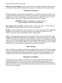
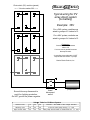
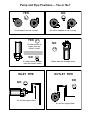
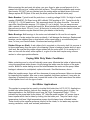
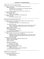
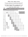
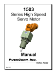
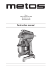
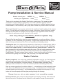
entric
SunC
TM
Pump Installation & Service Manual
Please record your
MODEL #_____
and for your application:
Volts _____
SERIAL #_____
Amps _____
Thank you for purchasing the Dankoff SunCentric™ water pump. This pump has been
successful in a wide variety of applications since 1989. It will work properly if these
instructions are followed carefully. If you have any questions or problems, please call your
Dankoff dealer, or call the factory. We try very hard to make our products work in all cases.
Please read the label on your pump, and enter the model and serial numbers in the spaces
above. This will help you to obtain parts or service in the future. Some SunCentric models
are used at more than one voltage. Volts and amps for your application will be found by
consulting the performance charts attached to this manual.
Solar Array Sizing for Non-Battery PV-Direct Systems Only
Please follow the specification sheet for power requirements, or ask your dealer or factory
for advice. Do NOT undersize your solar array. A slight under-sizing will cause the pump to
stall, and it may not function at all. (This is not a problem with battery systems.)
Tracking the sun: Your pump can be powered by a fixed array or a tracking array. With a
tracking array the solar array tilts to follow the sun as it travels accross the sky. Centrifugal
pumps loose capacity quickly, as solar intensity and motor speed decrease. Therefore, it is
most economical to use a tracking array with your pump. This will supply maximum power
throughout the day, rather than only at mid-day. Solar trackers are available from your
Dankoff dealer. The most common type is passive. It uses only the motion of fluid and vapor,
and the force of gravity, to tilt the rack. Like your pump, it is simple and reliable.
Weather Protection
Shelter is required. Your motor may overheat if exposed to very hot sun. Rain exposure
will greatly reduce bearing and brush life and will make the motor difficult to repair. If the
pump is to be used outdoors, it must be covered. The pump shelter must have some
opening to allow circulation of air from the outside to prevent overheating of the motor.
Here are some suggestions for outdoor shelters: 1. a curved piece of sheet metal with open
ends (the cover should be twice as long as the pump); 2. a metal barrel cut in half the long
way and placed over the pump; 3. any weatherproof box inverted over the pump; 4. a dog
house set it over the pump with the pipes passing through the doorway.
Damage from sun, rain or water exposure is not covered by warranty.
Freeze protection: The pump must be protected from freezing. Freezing water will crack
the cast iron parts. If the pump can be drained for cold weather storage by removing the
drain plug at the bottom of the pump.
Safety in case of leakage: A worn shaft seal will cause water leakage. Install the pump
so that water leakage will not submerge the pump or cause damage to the surroundings.
Overload Protection
Electrical overload can be caused by large debris or a mechanical fault in your pump or by
an electrical fault in the motor or in your wiring. If protection is not provided, this can cause
damage to your motor or other parts of your power system, including fire hazard. A circuit
breaker or fuse is the electrical “safety valve” that prevents such damage.
WARNING: Failure to install the required fuse or
circuit breaker will void your warranty.
Amp rating of fuse or breaker: Ampere rating = amps at the pump + 15-25%. Refer to
the performance chart for amps at the pump for your application.
Breakers: Most AC breakers cannot be used for DC circuits. Square-D® QO or QB-Series
breakers are an exception. They are UL-listed for low voltage DC systems up to 24V
nominal. They are commonly available at electric supply stores.
Fuses: Plastic plug-type automotive fuses are good for 24V nominal, 30 Amp Max. Paper
cartridge type FRN-R time-delay fuses are available for 30 amp maximum and are rated to
120VDC. A standard AC single-phase fused disconnect switch can be obtained to hold FRN
fuses. Do not use the small glass type of fuse. Keep spare fuses nearby. DO NOT substitute
a larger fuse to solve a problem. Place the fuse or breaker close to the power source, rather
than at the motor, so that it protects against both wiring and motor faults.
Wire Sizing
Wire of sufficient size should be used to keep voltage drop to less than 3%. Greater voltage
drop has a disproportionate effect on the performance of the pump, and can result in little or
no water reaching the outlet. Please consult a wire sizing chart that is appropriate for the
voltage of your system. Your Dankoff Solar Pump supplier can obtain this chart for you.
Direction of Rotation
The pump must run in direction of the arrow on the pump case (counterclockwise when
facing the pump intake). The direction of rotation is determined by the polarity of the
electrical connection to the motor. Check for proper direction of rotation by observing the
motor shaft when power is first applied. Reversal of the polarity (direction) for a few minutes
will not cause any damage.
Photovoltaic (PV) modules (panels)
entric
SunC
<––– 3 in series makes 36V –––>
TM
Typical wiring for PV
array-direct system
(no battery)
Example: 36V
For a 24V system, modules are
wired in groups of 2 instead of 3.
For a 48V system, modules are
wired in groups of 4 instead of 3.
Explanation
3 modules in series increases
volts to 36.
2 or more sets in parallel increases
the amps & watts.
A controller (current booster) is NOT
required with SunCentric™ pumps.
Dankoff Solar Products, Inc.
Ground the array framework to
earth for lightning protection.
Do NOT ground the power negative.
fused
disconnect
switch
pump motor
Voltag
ge Table for PV-Direct System
Nominal Volts
Working volts
Open Circuit Volts
12
16
20
24
32
40
36
48
60
"nominal" = the NAME of the voltage standard
in full sun with pump running +/– 10%
with pump disconnected in medium-full sun +/– 10%
Intake Piping
The most common problems that occur with all non-submersible water pumps are due to
mistakes made in the design and installation of the intake piping. Please follow these
instructions carefully. Most important, it is critical to minimize the suction load on the pump.
Place the pump as low and as close to the water source as you can. In NO case should the
pump be placed any higher than 10 vertical feet (3 m) above the surface of the water in the
source. (Subtract 1 foot from this number for every 1000 feet of elevation above sea level —
1 m for every km.)
Always keep pipe size as large, as direct, and as short as possible as possible. To reduce
friction losses, use a minimum of elbow fittings. Where possible, use 45° elbows instead of
90° elbows or use flexible suction hose. Refer to the pipe sizing chart in this manual, and
select a pipe size that will result in a very low pressure drop for your application.
Suction applications: If the pump must be placed higher than the water level in the
water source, extra attention must be paid to the suction piping. It should slope upward to
the pump without dips or high points, so that air pockets are eliminated. The highest point in
the suction piping should be the pump inlet except where liquid flows to the pump inlet
under pressure. The suction line should be built following the same rules as for a drain line,
to allow it to flow as easily as possible — except that the water will be drawn upward.
Foot valve: A foot valve must be used at the water intake, to keep the pump primed. Foot
valves are available from any local pump supplier, and from many hardware stores. To
prevent air from being drawn into suction pipe due to a suction whirlpool, the foot valve may
need to be submerged as much as three feet (1 m) below the low water level. This will NOT
add to the suction load on the pump. The suction pipe must be tight and free of air leaks or
the pump will not operate properly.
Intake screen: A foot valve that you can buy locally will have a perforated screen with
openings that are less than 1/8” (3 mm) in size. This is adequate to protect the pump.
If you are not using a foot valve, you should have an inline strainer to prevent particles
larger than 1/8” (3 mm) from entering the pump. Such particles may stick in the impeller and
reduce the performance, and may cause damage. An inline strainer can be purchased from
suppliers of pump, irrigation or swimming pool equipment. It should be large enough to
allow a substantial accumulation of material before it blocks the flow.
Discharge Piping
Discharge piping should never be smaller than the fittings on the pump, and should
preferably be one size larger. Refer to the pipe sizing chart at the end of this manual. A gate
valve can be installed in discharge line to serve as a shut-off during maintenance or for
throttling if the pumping rate is too high. With this type of centrifugal pump, it is safe to
restrict the flow in this manner. However, DO NOT run the pump for a long time against a
completely blocked discharge (a closed gate valve or a float valve). To do so can cause the
water to get very hot, sufficient to damage the pump.
Pump and Pipe Positions -- Yes or No?
YES
NO
Air escapes from top of pump
Air will be trapped at top of pump
YES
IF water source is
higher than the
pump's outlet
NO
NO
IF water source is lower
than the pump's outlet
INLET PIPE
NO
Water leak will damage motor
OUTLET PIPE
NO
Air will be trapped here
Air will be trapped here
Priming The Pump
The pump must be primed before starting. This means that the pump case and the intake
piping must be filled with water, with no air pockets. If the pump is higher than the water
source, the system must have a foot valve (see above) and a means to easily fill the pump
and the intake pipe with water. This must be easy to do without removing pipe fittings. It is
common practice to install a tee fitting at the pump outlet, pointing upward, with a ball valve.
If there is to be a check valve in the outlet pipe, then place this tee before the check valve.
Pour water into the priming valve until air stops rising out. If the pump does not start
immediately, stop and reprime it. If the pump is starting against pressure, it will help to keep
the priming valve open until flow is established. In difficult cases, a small hand pump can be
used to prime the pump. Hand pumps are available from marine suppliers.
Dry Run Prevention
The shaft seal in the pump will be quickly destroyed if the pump runs dry. A damaged seal
will cause leakage of water around the pump shaft. If it is possible for the water source to be
depleted, you may wish to install a float switch to disconnect the power if the water level
falls too low. The float switch must be rated to carry the DC voltage and current for your
application. Float switches are available from your Dankoff dealer.
Preventing Tank Overflow
A float valve can be used at the pump outlet to stop the flow upon filling a tank. However, if
the flow is 100% stopped, there is danger that the water in the pump can get very hot from
fluid friction and cause damage. A float valve installation should have an “imperfection”
established so that the flow is never completely stopped. An better method is to install a
float switch in the tank. The float switch must be rated to carry the DC voltage and current for
your application. Float switches are available from your Dankoff dealer.
Maintenance
Shaft Seal: Seals may last for a few years, but if the water contains abrasive silt, the seals
will wear faster. Seals will be quickly ruined if the pump runs dry. You can purchase spare
seals from your Dankoff dealer. Seals MUST be installed correctly. The smooth white
ceramic face must face outward, away from the motor. The part with the spring presses over
the shaft. The all-black end must contact the white ceramic face. The metal and rubber end
faces away from the motor.
Seal and Gasket Kits
If last digit of the pump model number is 1, 2, 3, or 4 — order Dankoff Solar item #37690
If last digit of the pump model number is 5 or 6
— order Dankoff Solar item #37691
Seal and Gasket Kits for High Temperature pumps
If last digit of the pump model number is 1, 2, 3, or 4 — order Dankoff Solar item #37695
If last digit of the pump model number is 5 or 6
— order Dankoff Solar item #37696
The seal is an industry-standard pump seal for 5/8” shaft. In case of emergency, you may be
able to obtain one from a local pump supplier or electrical repair shop. If the paper pump
gasket is damaged, a new one can be cut from thick paper. Manila file folders works fine.
Before pressing the seal parts into place, use your finger to wipe a small amount of oil or
grease onto the cast iron, rubber and shaft surfaces. This will make installation and service
much easier. DO NOT get any lubricant onto the mating white and black faces of the seal.
Always replace BOTH parts of the seal (the black part and the black & white part).
Motor Brushes: Typical brush life peak hours = working voltage X 800 / 3rd digit of model
number. EXAMPLE: PV-Direct curve #60 is Model 7526 working at 30V. Typical brush life =
30 X 800 / 2 = 12,000 peak hours. This represents about 5-8 years of service. Your result
may differ. New Brushes measure 1.25 inches (31 cm) in length. You can measure wear
after a period of time, to predict the brush life. Worn brushes will not effect performance, until
they are worn to about 1/2 inch (1 cm.). At that point, to motor will stop as contact is broken.
Replacement brushes may be obtained from your dealer or the factory.
Motor Bearings: Ball bearings in the motor are lubricated for life and do not require
maintenance. If water enters the motor accidently, it will damage the bearings. Replacement
bearings can be obtained from a local electric motor repair shop or an automotive parts
store, or from your Dankoff dealer. Purchase two bearings #6203Z.
Rubber Slinger on Shaft: A red rubber disk is mounted on the motor shaft. Its purpose is
to throw water away from the motor’s front bearing if there is leakage of water due to a worn
shaft seal. Be sure that this rubber slinger rotates with the motor shaft. If it is cracked or if it
does not turn with the shaft, either replace it, or glue it to the shaft coupler using silicone
sealant or other appropriate adhesive.
Coping With Dirty Water Conditions
Water containing sand or clay will naturally cause wear. Minimize the intake of abrasives by
using the appropriate intake screen. Avoid placing the intake near the bottom of the water
source. Watch for water leaking around the shaft between the motor and the pump. When
leakage is observed or anticipated, replace the seals. See Maintenance, above.
When the impeller wears, there will be a decrease of pump performance. Wear can be seen
by inspecting the impeller. After one or more impellers have been replaced, it may also be
necessary to replace the volute case. Inspect the inside of the volute case where the intake
of the impeller runs. Look for signs of wear.
Hot Water Applications
This applies to pumps that are used to circulate fluid hotter than 140°F (60°C). Applications
include solar water heating, hydronic floor heating, etc., not swimming pools or spas. For
these applications, the SunCentric must have the “High Temperature Option”. This is
indicated on the pump label by the letters “HT” after the model number. HT pumps have a
brass impeller which can be seen by looking into the intake port. They also have a high
temperature shaft seal. High temperature pumps should always have a flooded intake.
There should not be negative pressure (suction) at the intake, or hot water may vaporize
causing cavitation, noise, and reduced performance.
SunCentric Troubleshooting
–––––––––––––––––––––––––––––––––––––––––––––––––––––––––––––
Pump does not run (no shaft rotation)
– IF voltage at pump motor = 0 while voltage at power source is OK
Power circuit failure
Check the fuse or circuit breaker, see “Overload Protection”
Check the wires and connections
Check or bypass the float switch circuit, if there is one
– IF voltage at motor is normal
Motor brushes worn
Replace motor brushes
– IF voltage is very low or fuse blows or circuit breaker trips
Pump is jammed
See “Pump is jammed”, below
–––––––––––––––––––––––––––––––––––––––––––––––––––––––––––––
Pump turns but flow is less than normal
– IF system is solar-direct (no battery) and voltage at motor is below normal
PV (solar) array is undersized
See Minimum Array Size on the performance chart
PV array is wired wrong
Inspect, measure the voltage with pump disconnected (open circuit)
Open circuit voltage should be about 20V per “12V” increment
Array is positioned wrong
Partial shade or dirt on the PV array
Pump is partly jammed
See “Pump is jammed”, below
Undersized wire (see next line)
– IF system is battery OR solar-direct, and voltage at motor is below normal
Wire from power source to pump is undersized
With pump running, measure voltage at power source AND at motor
If difference (voltage drop) is greater than 3%, the wire is too small
(See “Wire Sizing”)
– IF voltage at motor is normal
Piping is undersized (See “Water Pipe Sizing Chart”)
Intake is restricted by debris
Outlet is restricted
Vertical lift is excessive
Pump is spinning in reverse
Reverse + and – wires
Impeller is clogged with debris
Air is trapped in a high spot in the pipe
Air is trapped in the pump
Rotate pump to one of the approved positions
Impeller is worn from abrasive silt
–––––––––––––––––––––––––––––––––––––––––––––––––––––––––––––
Pump does not stay primed
– IF it loses prime while the power is off
Foot valve is damaged
Replace foot valve
Foot valve is stuck open
Remove intake screen from foot valve, remove debris in valve
Improve screening of the water to reduce future problems
Leak in the intake pipe
Look for slow water leak when pump is stopped
Leak in the pump
Inspect for leakage at the gasket and the shaft seal
– IF pump loses prime while running
Tiny leak in the intake pipe is allowing air to be sucked in
Look for slight water leak when pump is stopped. If the leak is not
not visible, tighten threaded pipe joints or apply a hardening sealant
around the joints.
IF polyethylene (flexible black) pipe is used
Hose clamp connections are a frequent cause of intake leakage.
Install two clamps at each joint. Tighten them with a wrench. If
problem persists, pour hot water over the joint and tighten it more.
Vortex (whirlpool) forms at the intake, drawing air down from the surface
Increase submergence of the intake to eliminate the vortex
– IF suction lift is greater than 10 vertical feet (3 m)
Excessive suction releases vapor and dissolved gasses from water. The
resulting bubbles reduce the pump’s suction capacity. This is called “cavitation”.
Lower the pump closer to the water source, if possible
Reduce friction in the intake pipe by using larger pipe and/or
eliminating sharp 90 degree elbows. (See “Intake Piping”)
–––––––––––––––––––––––––––––––––––––––––––––––––––––––––––––
Pump is jammed, hard to turn, or has mechanical noise
The exposed shaft between the motor and the pump should be free enough to turn by hand.
It will offer resistance, but you should be able to turn it with two fingers.
– IF shaft will not turn a full rotation, or feels very hard to turn
Pump jammed by dirt or fibrous debris
Shaft coupling is loose
Check shaft set–screws. If tight, leave them be. If loose, align the holes
with the grooves in the motor shaft. Turn screws very tight.
– IF the pump is NEW and there is a soft rubbing noise
The impeller is rubbing slightly. Ignore it. It will wear away in a short time.
–––––––––––––––––––––––––––––––––––––––––––––––––––––––––––––
Water leaks from the pump shaft
– IF the pump is new or was just repaired
Shaft seal is installed backwards
– IF the pump is old
Shaft seal is worn from abrasive silt
– IF the pump has run dry
Shaft seal is damaged (burned) –– See “Maintenance”
=============================================================
Technical support, parts and service
Before calling for help or ordering parts, please have the following
information:
– Pump model number and serial number
– Is it a High Temperature (HT) model?
entric
SunC
TM
======================== WARRANTY ========================
SunCentric ™ pumps are warranted to be free from defects in
material and workmanship for two (2) years from date of purchase.
Failure to provide correct installation, operation, or care for the product, in accordance with
the instruction manual, will void the warranty.
Warranty does not cover damage due to sand or abrasive silt in the water, mishandling or
other abusive conditions, failure to protect from weather exposure, failure to protect from
overheating due to sun exposure, lightning, flood or other acts of nature.
Motor brushes and shaft seals are considered to be normally wearing parts
and are not covered under warranty.
Product liability, except where mandated by law, is limited to repair or replacement, at the
discretion of the manufacturer. Manufacturer is not responsible for incidental or
consequential damages or the labor or other charges necessitated by the removal,
transportation, or reinstallation of any defective product.
No specific claim of merchantability shall be assumed or implied beyond what is printed
on the manufacturer's printed literature. No liability shall exist from circumstances arising
from the inability to use the product, or its inappropriateness for any specific purpose. It is
the user's responsibility to determine the suitability of the product for any particular use.
In all cases, it shall be the responsibility of the customer to insure a safe
installation in compliance with local, state and national electrical codes.
============================================================
Water Pipe Sizing Chart
Friction Loss in Plastic Pipe with Standard Inside Diameter (SIDR)
THIS CHART APPLIES ONLY TO: PVC pipe, Schedule 40 (160 PSI) and to
PE (polyethylene) pipe with SIDR designation (most common 100 PSI black pipe)
HEAD LOSS in VERTICAL FEET per HUNDRED FEET of pipe
or VERTICAL METERS per HUNDRED METERS of pipe
FLOW
RATE
Nominal Pipe Diameter (Inches)
1/2 *
3/4
1
1 1/4
1 1/2
2
2 1/2
GPM L P M
.662
.82
1.05
1.38
1.61
2.07
2.47
1
2
3
4
5
6
7
8
9
10
11
12
14
16
18
20
22
24
26
2 8
30
35
40
45
50
55
60
65
70
75
80
85
90
95
100
150
200
1.13
4.16
8.55
14.8
22.2
31.0
.
.
.
.
.
.
.
.
.
.
.
.
.
.
.
0.14
0.35
2.19
3.70
5.78
7.85
10.6
13.4
16.9
20.3
24.3
28.6
.
.
.
.
.
.
.
.
.
.
.
.
.
.
.
0.05
0.14
0.32
0.53
0.81
1.00
1.52
1.94
2.43
2.93
3.51
4.11
5.47
7.02
8.73
10.6
13.3
14.9
.
.
.
.
.
.
.
.
.
.
.
0.02
0.05
0.09
0.16
0.25
0.35
0.46
0.58
0.72
0.88
1.04
1.22
1.64
2.10
2.61
3.16
3.79
4.44
5.15
5.91
6.72
8.94
11.0
14.2
17.3
.
.
.
.
.
.
.
.
.
.
.
.
.
0.02
0.05
0.09
0.12
0.18
0.23
0.30
0.37
0.46
0.53
0.65
0.85
1.09
1.34
1.64
1.96
2.31
2.66
3.05
3.46
4.62
5.91
7.37
8.96
10.7
12.5
14.5
16.7
19.0
.
.
.
.
.
.
.
.
.
.
0.02
0.04
0.07
0.08
0.09
0.12
0.16
0.18
0.21
0.28
0.37
0.46
0.55
0.67
0.79
0.90
1.04
1.18
1.57
1.99
2.49
3.03
3.60
4.23
4.90
5.64
6.40
7.21
8 .06
8.96
9.91
10.9
23.1
.
.
.
.
.
.
0.02
0 .03
0.05
0.06
0.07
0.08
0.09
0.12
0.14
0.18
0.21
0.25
0.30
0.35
0.42
0.46
0.62
0.79
0.97
1.20
1.43
1.66
1.94
2.22
2.52
2.84
3.19
3.53
3.90
4.30
9.10
15.5
3.8
7.6
11
15
19
23
27
30
34
38
42
46
53
61
68
76
83
91
99
106
114
133
152
171
190
208
227
246
265
284
303
322
341
360
379
569
758
* NOTE: 1/2"
data applies to
PE pipe only.
PVC has smaller
ID of .612"
.
.
.
.
.
.
.
.
.
.
3
4
5
6
3.07
4.03
5.05
6.06
actual Inside Diameter (inches)
.
.
.
.
.
.
.
.
.
.
.
.
NOTE: Shaded values are
.
.
.
.
at velocities over 5 feet per
.
.
.
.
second and should be
.
.
.
.
selected with caution.
.
.
.
.
.
.
.
.
.
.
.
.
0.02
.
.
.
0.03
.
.
.
0.04
.
.
.
0.05
.
.
.
0.06
.
.
.
0.07
.
.
.
0.08
0.02
.
.
0.09
0.03
.
.
0.11
0.04
.
.
0.14
0.05
.
.
0.16
0.05
.
.
0.18
0.06
.
.
0.23
0.07
.
.
0.30
0.09
0.02
.
0.37
0.12
0.04
.
0.46
0.14
0.05
.
0.55
0.16
0.06
.
0.65
0.18
0.07
0.02
0.74
0.22
0.08
0.03
0.85
0.25
0.09
0.04
0.97
0.28
0.10
0.05
1.09
0.32
0.12
0.06
1.22
0.37
0.13
0.07
1.36
0.39
0.14
0.08
1.50
0.44
0.16
0.09
1.66
0.49
0.18
0.12
3.51
1.04
0.37
0.16
5.98
1.76
0.62
0.28
Innovative Solar Solutions • 2725 Westinghouse Blvd Suite 100 • Charlotte, NC 28273 • (866) 856-9819 • www.innovativesolar.com