1
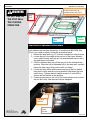
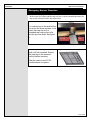
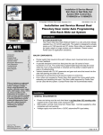
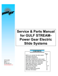
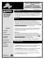
Owner's Manual Step Well
Covers
9010000766, 9010000828,
9010000775 and 9010000829
Content
WARNING
DO NOT RIDE ON
THE STEP WELL
TRAY DURING
OPERATION.
© Copyright Power Gear Issued: May 2014
3010002928, Rev. OB
Introduction
The Step Well Covers manufactured by Power Gear are designed for
the front-entry coaches. The step well covers provides comfort and
foot support for the person riding in the passenger seat. The step well
cover also adds user safety by preventing accidental falls into the
entry step well.
Operation
Extension:
Before extending the step well tray, verify that there are no
obstructions in the step well that will interfere with the travel of the
step well tray. Locate the step well tray rocker switch and position
yourself fully inside the coach and clear of the step well tray path. Do
not stand in the entry step well. Press and hold the rocker switch until
the step well tray is fully extended and stops moving.
CONTENTS
Introduction
1
Operation
1
Parts Break Down 1
Limit Switch
Adjustment
2
Wiring Diagram
3
Emergency Retract
procedure
4
Preventative
Maintenance
5
Verify that the step well tray is fully extended by visually checking to
see that the step is level and parallel to the main coach floor with
minimal space to door frame.
Retraction:
Before retracting the step well tray, first make sure that there is
nothing lying on the top of the step well tray. Locate the step well tray
rocker switch and position yourself fully inside of the coach. Do not
stand on the step well tray. Press and hold the rocker switch until the
step well tray is fully retracted and stops moving.
Verify that the step slider is fully retracted by visually checking to see
the step well tray is flush with the front part of the step well base.
Parts Break Down
The construction of the step well consists of three primary parts:
The Step Well Tray (see page 2) is the portion of the step well that
extends and that the user sees during the normal operation.
The Step Well Base (see page 2) connects directly to the chassis of
the motor home and provides the structural support and
environmental protection for the linear actuator and step slider.
1217 E. 7th St.
Mishawaka, IN 46544
www.powergearus.com
The Linear Actuator (see page 2) is responsible for providing the
power to drive the slider in and out.
Page 1 of 5
3010002928
Step Well Cover Operating
WARNING
DO NOT RIDE ON
THE STEP WELL
TRAY DURING
OPERATION.
Limit Switch only on
models before may 2014
Step
Tray
Step Well
Base
Linear
Actuator
Limit Switch Adjustment Procedure
Limit switches are set from the factory on models built BEFORE May
2014; if you need to adjust it follow the procedure below.
1. Retract the step well tray 12" from the intended out stop position.
2. Locate the pin in the shaft at the rod end of the linear actuator.
Look under the step well tray as it is extended and remove the rclip and the pin from shaft.
3. Pull the unpinned step tray all the way out to the intended stop
position. Once the tray is extended fully in the step well, securely
clamp the step tray in that position with a c-clamp.
4. Loosen the limit switch slide screws and move the limit switch
back until it clicks and the out stop bracket holds down the limit
switch lever. Tighten the limit switch screws to 5 Inch LBS to
secure the limit switch in that position.
5. Push step tray back to the rod of the linear actuator and connect
the pin and r-clip. Use step well tray as designed.
Out Stop
Bracket
1217 E. 7th St.
Mishawaka, IN 46544
www.powergearus.com
Limit
Switch
Page 2 of 5
3010002928
Step Well Cover Operating
Wiring Diagram
WARNING
Do not step on the
slider when linear
actuator is not
attached to the base
assembly as it will
not support a load.
Step well cover made BEFORE May 2014 will have 1510000254 wiring
harness on the following step well 9010000766, 9010000828,
9010000775 and 9010000829.
Part Number 1510000254
Linear
Actuator
Connector
Switch
Input
Connector
Limit
Switch
3
Step well cover made AFTER May 2014 will have 1510000274 wiring
harness on the following step well 9010000766, 9010000828,
9010000775 and 9010000829.
Part Number 1510000274
Switch
Input
Connector
Linear
Actuator
Connector
+12VDC on pin 2 and Ground on Pin 3 will extend the step well cover.
Ground on pin 2 and +12VDC on Pin 3 will retract the step well cover.
Page 3 of 5
3010002928
Step well Cover Operation
Emergency Retract Procedure
In the event of a failure and the step well tray is in the extended position, the
tray can be released. Follow the steps below:
Figure 1
1. Locate the pin in the shaft at the
rod end of the linear actuator. Look
under the step tray as it is
extended and remove the r-clip
and the pin from shaft. See figure
1.
2. Push the step tray into the outer
shell until fully retracted. Secure
the step tray in the retracted
position before traveling.
R-Clip
Pin
Step well tray shown in retracted position
Take the coach to an O.E.M
certified dealer for repairs.
Page 4 of 5
3010002928
Step Well Cover Operating
Preventative Maintenance
NOTE
Silicone lubricants and
WD-40 are not
recommended as they
have a tendency to
evaporate and dry the
mating surfaces which
leave them vulnerable to
the elements.
1. Maintain clean and dry electrical connections at the two –way (motor
connector) and three-way (switch connector) connectors. Inspect and
clean all electrical connections every 12 months.
2. Clean all mud, salt, and road grime from the ball bearing slides before
lubricating. Wipe the ball bearing slides with a clean dry rag. Lubricate
with a dry lubricant that has Teflon as one of the properties. If the ball
bearings slider squeaks or makes noises, apply the dry lubricant to
prevent and / or stop squeaks.
3. When the step tray is extended, visually inspect the ball bearings for
damage, road grime or debris. Check for excess build up of dirt or other
foreign material; remove any debris that may be present.
Additional Reference Documents Located at www.powergearus.com
3010003119
Service Manual Step well Covers 9010000766, 9010000828,
9010000775 and 9010000829
Power Gear Limited Warranty
Power Gear warrants its manufacturer installed Power Gear and Kwikee brand
products to be free of material and workmanship defects for two (2) years from the
date of the original sale of the motor vehicle/recreation vehicle (RV) in which they are
installed, provided that these products are installed and operated according to the
purpose for which they were intended, designed and specified. This warranty does
not cover product that is incorrectly installed, or upon examination has been misused
or abused by the vehicle owner.
Warranty coverage includes:
• Repair or replacement of the defective component(s) of the malfunctioning
system. Entire systems are not replaced unless either the faulty component
is not replaceable or all components comprising the system are defective.
• Labor costs for the diagnosis and repair work associated with the repair or
replacement of the defective component(s) by a licensed servicing center.
This warranty does not include payment or reimbursement of:
• Normal system maintenance and preventive maintenance.
• Mobile service or towing expenses related to field repairs and/or the
transportation of the vehicle to a repair facility.
• Living or travel related expenses incurred in the repair of the vehicle.
By filing a warranty claim in accordance with Power Gear’s Warranty Administration
Procedure, service providers agree that the replacement part(s) will be provided to the
vehicle owner at no cost and that the total labor charges for the completion of
warranty repairs will be billed to Power Gear. Accordingly, under no circumstances
will Power Gear reimburse the vehicle owner directly for costs covered under this
warranty policy.
Warranty coverage runs concurrently with any vehicle warranty period provided by the
manufacturer, and is transfer-able to subsequent owners. Proof of original date of
purchase of vehicle, and if applicable subsequent owner’s proof of purchase, is
required to confirm coverage.
Power Gear reserves the right to change the terms of our warranty policy at any time.
For the most current information on product warranty and our warranty claim
procedure, visit our website at www.powergearus.com.
Page 5 of 5