1
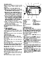
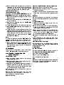
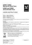
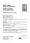
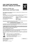
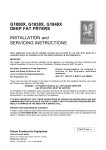
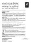
G2962, G2994,
Manual-tilt Bratt Pans
G2965 and G2995
Auto-tilt Bratt Pans
INSTALLATION and
SERVICING INSTRUCTIONS
These appliances must be installed and serviced by a qualified person as stipulated by the Gas Safety
(Installation & Use) Regulations.
IMPORTANT
The installer must ensure that the installation of the appliance is in conformity with these instructions and
National Regulations in force at the time of installation. Particular attention MUST be paid to -
I.E.E Regulations for Electrical Installations
Electricity At Work Regulations
Gas Safety (Installation & Use) Regulations
Health And Safety At Work etc. Act
Local and National Building Regulations
Fire Precautions Act
Detailed recommendations are contained in
Institute of Gas Engineers published
documents :
IGE/ UP/ 1, IGE/ UP/ 2
BS6173 and BS5440
These appliances have been CE-marked on the basis of compliance with the Gas Appliance Directive,
EMC and Low Voltage Directive for the Countries, Gas Types and Pressures as stated on the data plate.
WARNING - TO PREVENT SHOCKS, ALL APPLIANCES WHETHER
GAS OR ELECTRIC MUST BE EARTHED.
On completion of the installation, these instructions should be left with the Engineer-in-Charge for reference
during servicing. Further to this, The Users Instructions should be handed over to the User, having had a
demonstration of the operation and cleaning of the appliance.
IT IS MOST IMPORTANT THAT THESE INSTRUCTIONS BE CONSULTED BEFORE INSTALLING AND
COMMISSIONING THIS APPLIANCE. FAILURE TO COMPLY WITH THE SPECIFIED PROCEDURES MAY
RESULT IN DAMAGE OR THE NEED FOR A SERVICE CALL.
PREVENTATIVE MAINTENANCE CONTRACT
In order to obtain maximum performance from this unit we would recommend that a maintenance contract be
arranged with SERVICELINE. Visits may then be made at agreed intervals to carry out adjustments and
repairs. A quotation for this service will be given upon request to the contact numbers below.
WEEE Directive Registration No. WEE/DC0059TT/PRO
At end of unit life, dispose of appliance and any replacement parts
in a safe manner, via a licenced waste handler.
Units are designed to be dismantled easily and recycling of all
material is encouraged whenever practicable.
Falcon Foodservice Equipment
HEAD OFFICE AND WORKS
Wallace View, Hillfoots Road, Stirling. FK9 5PY. Scotland.
SERVICELINE CONTACT PHONE - 01438 363 000
FAX - 01438 369 900
T100723 Ref. 2
Warranty Policy Shortlist
Warranty does not cover :Correcting faults caused by incorrect installation of a product.
Where an engineer cannot gain access to a site or a product.
Repeat commission visits.
Replacement of any parts where damage has been caused by misuse.
Engineer waiting time will be chargeable.
Routine maintenance and cleaning.
Gas conversions i.e. Natural to Propane gas.
Descaling of water products and cleaning of water sensors where softeners/conditioners are not fitted, or are
fitted and not maintained.
Blocked drains.
Independent steam generation systems.
Gas, water and electrical supply external to unit.
Light bulbs.
Re-installing vacuum in kettle jackets.
Replacement of grill burner ceramics when damage has been clearly caused by misuse.
Where an engineer finds no fault with a product that has been reported faulty.
Re-setting or adjustment of thermostats when unit is operating to specification.
Cleaning and unblocking of fryer filter systems due to customer misuse.
Lubrication and adjustment of door catches.
Cleaning and Maintenance
Cleaning of burner jets
Poor combustion caused by lack of cleaning
Lubrication of moving parts
Lubrication of gas cocks
Cleaning/adjustment of pilots
Correction of gas pressure to appliance.
Renewing of electric cable ends.
Replacement of fuses
Corrosion caused by use of chemical cleaners.
SECTION 1 - INSTALLATION
UNLESS OTHERWISE STATED, PARTS WHICH HAVE BEEN PROTECTED BY THE MANUFACTURER
ARE NOT TO BE ADJUSTED BY THE INSTALLER.
1.4 GAS SUPPLY
1.1 MODEL NUMBERS, NETT WEIGHTS
and DIMENSIONS
MODEL
G2962
G2965
G2994
G2995
WIDTH
mm
DEPTH
mm
HEIGHT
mm
WEIGHT
kg
WEIGHT
lbs
600
600
900
900
770
770
770
770
870
870
870
870
120
120
165
165
265
265
364
364
1.2 SITING
The unit should be installed on a level, fireproof
surface, in a well lit and draught free position within a
suitably ventilated room. If floor is constructed of
combustible material then local fire requirements
should be checked to ensure compliance. A clear
space of 150mm should be left between unit rear and
any combustible wall. A minimum vertical clearance
of 900mm above top edge of appliance is required.
Important
The incoming service must be of sufficient size to
supply full rate without excessive pressure drop.
The gas meter should be checked, preferably by the
gas supplier to ensure meter is adequate to deal with
rate of gas supply required for the unit in addition to
any other gas equipment installed.
Installation pipes should be fitted in accordance with
IGE/UP/2. The size of pipework from meter to unit
must be not less than unit inlet connection Rp1/2 (1/2"
BSP female). An isolating cock that is easily
accessible to user, must be located close to unit to
allow shut down during any emergency or routine
servicing. The installation must be tested for gas
tightness. Details are given in IGE/UP/1.
The gas supply tubing or hose must comply with
national requirements in force and require to be
periodically examined and replaced as necessary.
1.5 ELECTRICAL SUPPLY
If unit is to be installed in a suite formation with
matching units then instructions for all models should
be consulted in order to determine necessary
clearances to any combustible rear wall or overlying
surface(s). Some units require greater clearances
than others. The largest figure quoted in the individual
instructions will therefore determine clearance of the
complete suite adjoining appliances.
Flue discharges vertically along top rear of unit
THERE MUST BE NO DIRECT CONNECTION OF
THE FLUE TO THE OUTSIDE AIR OR TO A
MECHANICAL EXTRACTION SYSTEM.
See Section 1.3 for ventilation details.
After appliance position has been established, it is
recommended that the feet (on a unit fitted with feet)
be secured to floor using holes provided.
These appliances are designed for operation on a
230V 50Hz 3A electrical supply.
As mains lead wire colours may not correspond with
the markings which identify plug terminals, proceed
as follows:
The wire coloured GREEN and YELLOW must be
connected to plug terminal which is marked with the
letter E or the earth symbol or coloured GREEN or
GREEN and YELLOW.
The wire coloured BLUE must be connected to
terminal marked with letter N or coloured BLACK.
The wire coloured BROWN must be connected to
terminal marked with letter L or coloured RED.
1.3 VENTILATION
1.7 TOTAL RATED HEAT INPUTS
NATURAL and PROPANE GAS
Sufficient ventilation, natural or mechanical, must be
provided to supply adequate fresh air for proper
combustion.
It should also prevent occurrence of unacceptable
concentrations of substances harmful to health in the
location where equipment is installed. It is also
required to be able to remove any such products
that may occur, safely and efficiently.
Recommendations for Ventilation of Catering
Appliances are provided in BS5440 : 2. For multiple
installations, requirements for individual appliances
should be added together. Installation should be
made in accordance with local and/or national
regulations which apply at the time.
A qualified installer MUST be employed.
1.6 WATER SUPPLY
Not applicable to these appliances.
Model
G2962/2965
G2994/2995
kW (nett)
10.2
15.9
Btu/hr (gross)
38,300
59,700
1.8 INJECTOR SIZES NATURAL and PROPANE GAS
G2962/2965
MAIN BURNER
RH
MAIN BURNER
LH
PILOT
BURNER
CROSS-LIGHTING
BURNER
G2994/2995
MAIN BURNER
RH
MAIN BURNER
CENTRE
MAIN BURNER
LH
PILOT
BURNER
CROSS-LIGHTING
BURNER - LH
CROSS LIGHTING
BURNER - RH
NATURAL
PROPANE
Amal 470
Amal 400
SIT No. 36
Amal 75
Amal 180
Amal 140
SIT No.19
Amal 20
NATURAL
PROPANE
Amal 490
Amal 400
Amal 430
SIT No. 36
Amal 75
Amal 85
Amal 190
Amal 190
Amal 190
SIT No. 19
Amal 20
Amal 20
2.1 ASSEMBLY
Position unit and level by adjusting leg levelling feet
or castors as appropriate. Each foot (on units with
feet) contains a hole to enable floor fixing to be made.
2.1.1 Units on Castors
Refer to addendum T100286 supplied.
In addition, drain pan contents before attempting to
move unit. Also, lower pan prior to moving.
2.2 CONNECTION TO THE GAS SUPPLY
Inlet connection terminates at bottom RH corner
when viewed from rear and is Rp1/2 (1/2" BSP
Female). Test for gas tightness. The integral gas
supply, downstream of gas valve, may be checked by
applying leak detection spray with burner lit.
2.3 CONNECTION TO ELECTRICITY SUPPLY
1.9 GAS PRESSURE
The unit operates at the following pressures -
Operating Pressure
SECTION 2 - ASSEMBLY and
COMMISSIONING
Supply Pressure
NATURAL PROPANE NATURAL PROPANE
15 mbar
37 mbar
20 mbar
37 mbar
6 in. w.g. 14.8 in. w.g. 8 in. w.g. 14.8 in. w.g.
Ignition Pressure
NATURAL PROPANE
5 mbar 17.5 mbar
2 in. w.g. 7 in. w.g.
Ignition and operating pressures are measured at
oulet test point located on front face of
multi-functional control - see Figure 1 (Servicing
Section 3.8)
1.10 BURNER ADJUSTMENT
The only adjustment necessary on main burner is the
correct setting of gas pressures as described in
Section 1.9.
No aeration adjustment is provided.
Pilot flame should envelop approximately 6mm to
10mm of thermocouple tip.
If any adjustment is required, unit must be serviced.
Make electrical connection.
Unit is designed for connection to a 230V AC supply.
A 2 metre long mains lead is fitted as standard.
Mains lead wires are coloured in accordance with the
following code:
Green and Yellow
Blue
Brown
Earth
Neutral
Live
The wires should be connected to plug as follows:
EARTH to terminal marked E, or coloured GREEN.
NEUTRAL to terminal marked N or coloured BLACK.
LIVE to terminal marked L, or coloured RED.
Unit must be protected by 3 amp fuse if 13 amp
(BS1363) plug is used. Any other type of connection
must be protected by 5 amp fuse at distribution board.
Warning
THIS APPLIANCE MUST BE EARTHED.
2.4 CONNECTION TO THE WATER SUPPLY
Not applicable to this appliance.
2.5 PRE-COMMISSIONING CHECK
Important
After installation, the engineer should check that all
gas connections are tight and do not leak. Also check
that all electrical connections are secure.
The installation engineer should check that unit is
operating satisfactorily before leaving kitchen.
Particular attention should be given to pressure
settings detailed in Section 1.9 and pilot adjustment
as detailed in Section 1.10.
2.6 INSTRUCTION TO USER
After installing and commissioning appliance, please
hand User Instructions to user or purchaser and
ensure that person(s) responsible understand the
instructions and procedures for lighting, cleaning and
correct use of appliance.
It is important to ensure that locations of gas isolating
cock and electrical socket or switch are made known
to user and procedures for operating these in an
emergency be demonstrated.
SECTION 3 - SERVICING and
CONVERSION
Important
BEFORE ATTEMPTING ANY SERVICING, SWITCH
APPLIANCE OFF AT MAIN GAS AND
ELECTRICITY SUPPLY ISOLATORS. CARE MUST
BE TAKEN TO ENSURE THESE ARE NOT
INADVERTENTLY SWITCHED ON DURING TASK.
Certain operations require pan to be tilted or the
activator repositioned with control panel removed.
If this is done electrically, care should be taken not to
touch any live terminals and that control panel is
supported adequately so that none of the live switch
parts or thermostat terminal can touch earthed parts.
General Note
AFTER ANY MAINTENANCE TASK, CHECK
APPLIANCE TO ENSURE IT PERFORMS
CORRECTLY. CARRY OUT ANY NECESSARY
ADJUSTMENTS AS DETAILED IN THE
APPROPRIATE SECTION OF THIS DOCUMENT.
After carrying out any servicing or exchange of gas
components -
ALWAYS CHECK FOR GAS TIGHTNESS
3.1 CONVERSION
When changing from one gas family to another
always ensure the following Change main, pilot and cross-lighting burner
injectors. Refer to Section 1.8. Injectors must be
re-sealed using thread sealant.
Set pressures (REG ADJ, 1 STEP ADJ & NO PR).
Refer to Section 3.8.
Adjust pilot flame length. Refer to Section 1.10.
Change data plate.
For detailed procedure, refer to appropriate section in
this document.
3.2 REMOVAL OF CONTROL PANELS
Main Panel
Ensure pan is in DOWN position.
Pull off thermostat control knob.
On G2962 and G2994 models, remove handwheel by
undoing central fixing.
Open drop down door.
Remove fixings at corners of control panel bottom
edge and also those in top flange.
Pull panel clear of appliance and carefully rest it on
floor. Take care not to strain wiring.
Replace in reverse order.
Lower Inner Panel
Remove main panel before removing fixings
for lower panel and pull clear.
3.3 BURNERS
Removal Of Main Burners
Tilt pan to full position to allow access to burner
compartment.
Remove fixings that retain burners to base of
compartment.
Slide burner from injector and remove.
Replace in reverse order.
3.4 INJECTORS
3.4.1 Removal Of Main Burner Injectors
Remove main burners as detailed in Section 3.3.
Undo injectors or injector jets as required.
Replace in reverse order taking care that correct
injector is fitted to each burner. Injectors must be
re-sealed using thread sealant.
3.4.2 Removal Of Cross Lighting Burner
Remove main control panel. (See Section 3.2)
Tilt pan to fully raised position. On G2962/G2994
models, temporarily re-fit handle upon shaft.
On G2965/G2995, drop-down door must be closed
to operate foot bellows.
Undo compression fitting nut at cross-lighting burner
base.
From top, remove fixings that secure cross-lighting
burner and remove burner by lifting it up.
Replace in reverse order.
3.4.3 Removal Of Cross Lighting Injector
The complete burner can be removed as detailed in
Section 3.4.2. Alternatively, injector can be removed
leaving burner in position. To achieve this, remove
control panel, undo compression fitting nut and
remove fitting from burner venturi tube.
Injector can now be removed for renewal or cleaning.
When re-assembling, the injector must be re-sealed
using thread sealant.
3.4.4 Removal Of Pilot Burner Assembly
Remove both control panels and fully raise pan (see
Section 3.2). On G2962/G2994 models, temporarily
replace tilting handle and fully raise pan.
On G2965 and G2995, drop down door must be
closed to operate foot bellows.
Undo fixings that secure pilot assembly to base of
burner compartment.
In controls compartment, pull off electrode lead
connector at spark igniter and undo thermocouple
and pilot supply pipe connections at rear of
multi-functional control.
Remove assembly complete with pilot supply pipe by
pulling up and away from base of burner
compartment.
Replace in reverse order, ensuring thermocouple end
is clean (do not use thread compound) and do not
over tighten.
Ensure pilot supply pipe is correctly fitted and check
for leaks using soapy water.
Adjust pilot to achieve flame as detailed in
Section 1.10.
This is achieved by turning pilot adjusting screw
(see Figure 1) clockwise to reduce and vice versa.
After making any adjustment, ensure cross-lighting
burner ignites quickly from pilot.
3.5 REMOVAL OF THERMOCOUPLE
Remove main control panel.
Remove main burners as detailed in Section 3.3.
Undo thermocouple connection at pilot and
multifunctional control valve and remove.
Replace in reverse order ensuring thermocouple is
pushed fully into pilot bracket before tightening
connection.
3.6 PIEZO IGNITER/ SPARK IGNITER
3.6.1 Removal Of Spark Electrode
Follow procedure detailed in Section 3.5.
Undo connection to pilot burner to remove electrode.
Undo lead connection to electrode.
Replace in reverse order ensuring connection to pilot
assembly is not overtight as to crack electrode.
3.6.2 Piezo Unit
The igniter is a Piezo spark type and contains no
battery. The unit is located on LH side of gas control
unit mounting bracket secured by two fixings.
A faulty unit cannot be serviced and must be
replaced.
3.7 THERMOSTAT
3.7.1 Control Thermostat
To Remove
a) Remove main control panel as Section 3.2.
b) Raise pan fully.
c) Remove phial clamping plates on pan underside.
d) Pull off connections, noting their locations.
e) Remove fixings that secure thermostat to bracket.
f) Remove thermostat, threading capillary tube and
phial through apertures.
g) Replace in reverse order. Ensure capillary bulb and
sleeving are in identical position to that of original
component.
3.7.2 High Temperature Limit Device
The device is set to trip when centre oil temperature
at a maximum depth of 50mm reaches 225oC.
It should not be interfered with unless cut-out has
occurred and device requires to be re-set.
To Re-set
a) Remove main control panel (as Section 3.2).
b) Press centre spindle pin in until a click occurs.
c) Replace control panel.
To Replace
a) Carry out operations (a) and (b) (as Section 3.7.1).
b) Remove phial clamp from pan underside.
c) Pull off connections, noting respective locations.
d) Remove fixing that securs thermostat body to
bracket.
e) Remove thermostat, threading capillary tube and
phial through apertures.
f) Replace in reverse order. Ensure capillary bulb and
sleeving are in identical position to that of original
component.
1.
To Check Operation
Operation of high temperature limit device must be
checked at regular intervals adopting following
procedure:
a) Remove main control panel as Section 3.2.
b) Refer to wiring diagram. Bypass user thermostat
by supplying power directly to gas control valve
from live connection of main terminal block.
c) Fill pan with oil to recommended depth of 50mm for
deep frying and install a means of measuring oil
temperature. Measuring sensor must be placed at
geometric pan centre and 25mm below oil surface.
d) Light unit and observe rising oil temperature.
If functioning properly, limit device will cut off power
when oil temperature is between 220oC and 225oC
(maximum). If device fails to operate at maximum
temperature of 230oC, shut off unit immediately by
pressing OFF button on gas control valve and
carry out investigations to find the fault.
e) When limit device is functioning correctly,
reconnect user thermostat and when oil cools
sufficiently, re-set limit device.
f) Ensure user thermost operates correctly.
Warning: Never leave a unit with users thermostat
bypassed.
3.8 GAS CONTROL UNIT
(MULTIFUNCTIONAL CONTROL)
The gas control unit combines gas governor, flame
failure safety device and push buttons for start and
shut down.
Before removing, ensure main gas and electricity
supplies are shut off.
To Remove Gas Control Unit
Remove control panels as detailed in Section 3.2.
Remove terminal cover from control unit and remove
terminal wires.
Undo compression-fitting nut on gas inlet pipe at
control unit.
Undo compression fitting nut on burner gas pipe at
the rear of solenoid valve.
Disconnect supply wires to solenoid valve, first
remove tape that binds cables together. (It is not
possible to remove connections at solenoid itself).
Disconnect pilot supply pipe and thermocouple at rear
of control unit.
Pull off wire from spark igniter.
From below base, undo fixings that secure control
unit mounting bracket. Remove unit complete with
spark igniter, solenoid valve and bracket.
Disconnect spark igniter, solenoid valve and
mounting bracket from existing control unit and re-fit
to eplacement.
Re-fit new assembly and replace in reverse order.
2.
3.
5.
6.
11.
7.
10.
12.
9.
1. Inlet pressure test point
2. Pilot Adj.
3. 1st Step Adj.
4. Pilot Button
5. Reg. Adj.
6. Outlet pressure test point
Figure 1
8.
4.
7. No PR
8. Off Button
9. Thermocouple Connection
(below)
10. Main Burner Button
11. Pilot Connection (below)
12. Piezo igniter button
To Adjust Gas Pressure
(Natural Gas Appliances Only)
Refer to Figure 1. Remove screw from outlet test
point and connect gauge. Remove protective cap
marked NO PR and ensure the screw below is turned
fully clockwise. (Unless this is done, the governor
section of control is rendered inoperative).
Then proceed as follows:
a) Light burner and turn 1 STEP ADJ screw fully
clockwise.
b) Remove plastic cap from REG ADJ screw. Turn
screw to adjust outlet pressure as necessary.
(Clockwise to increase and vice-versa)
c) Turn 1 STEP ADJ screw anticlockwise by no more
than an eighth of a turn. If necessary re-adjust
REG ADJ screw to restore correct pressure.
d) Extinguish burner by turning thermostat control
knob OFF.
e) Re-light burner by turning thermostat knob to '5'
while observing pressure gauge. Pressure should
initially be approx. 5 mbar, pausing for a brief
period at this pressure before rising to full desired
burner pressure of 15 mbar.
f) If when performing operation (e), pressure is less
than 5 mbar, open 1 STEP ADJ screw a further
eighth turn and re-adjust the REG ADJ screw as
necessary to restore correct burner pressure.
Repeat operations from (d).
g) When satisfied that burner pressure is correct and
two-stage ignition pressure facility produces
smooth lighting of burner, turn gas off and replace
pressure test point screw and protective caps.
To Adjust Gas Pressure
(Propane Appliances Only)
Instructions for setting STEP OPENING facility on
ELECTROSIT gas control valve (Refer to Figure 1).
1. Remove outlet pressure test point screw and fit
pressure gauge.
2. After removing protective cap, turn NO PR screw
fully anti-clockwise.
3. After removing protective cap, turn 1 STEP ADJ
screw fully clockwise.
4. Light pilot and push main burner button to the right.
5. Open 1 STEP ADJ screw very slightly (approx. an
eighth of a turn).
6. Light burner by turning thermostat control to '5' and
observe pressure gauge. Pressure should initially
be 17.5 mbar then pause briefly before rising to full
outlet pressure. If 17.5 mbar is not initially
registered then turn thermostat knob to "OFF"
and repeat from Step 5.
Note
It must be emphasised that the 1 STEP ADJ screw
must be turned by very small increments only,
NEVER more than an eighth turn at any one time.
7. When satisfied that burner lights smoothly and
progressively from STEP OPENING facility,
remove pressure gauge, fit screw and refit plastic
protective covers.
3.9 GOVERNOR
The governor is incorporated in the multi-functional
control. See Section 3.8 to remove and adjust.
3.10 CHECKING and SERVICING THE
GAS CONTROL UNIT
Pilot Will NOT Light
a) Main gas supply must be turned on and pilot gas
supply line purged of air.
b) Press start button, apply a light to pilot and hold in
for approximately 30 seconds.
c) If pilot will not light after above procedure, there is a
possible obstruction to gas flow. This could be a
clogged pilot or tubing orifice. Alternatively, pilot
gas adjustment screw may be closed.
The pilot flame should envelop 6 to 10mm of
thermocouple tip.
Remove pilot adjustment screw cap, turn inner
adjustment screw clockwise to decrease, or
anti- clockwise to increase pilot flame.
Replace cap screw.
Pilot Goes OUT When Start Button is Released
a) Check pilot flame adjustment as above.
b) Check that thermocouple to control unit connection
is clean and secure.
c) If power unit does not hold, replace thermocouple.
If this does not correct condition, replace control
unit.
Checkout
Put lighting sequence into operation and observe,
through a complete cycle that main burner functions
properly.
To Light The Burners
a) Switch off electricity supply to pan and turn
thermostat control OFF.
b) Press and hold pilot button in fully while repeatedly
pressing and releasing igniter button until pilot
lights, observe through sight-hole.
c) Keep pilot button pushed in fully for 20 seconds
then release it. Pilot should remain alight but
should it go out, push in OFF button and wait
3 minutes before repeating from Step (b).
d) With pan fully lowered, push main burner button to
right.
e) Turn electricity on and check red neon lights.
Set thermostat control to desired setting and main
burner will light.
If Main Burner Does Not Light
If burner does not light, high temperature limit device
may have tripped. To re-set, refer to Section 3.7.2.
Investigate reason for trip.
To Shut Down
For Short Periods
Turn thermostat knob OFF. This leaves only pilot lit.
For Longer Periods (Complete Shut-down)
a) Turn thermostat knob to OFF.
b) Push in gas control OFF button.
c) Turn off electricity to appliance.
Note
Gas control is fitted with a safety interlock, therefore a
period of 3 minutes will elapse before it is possible to
re-light after complete shut-down.
3.11 GAS SOLENOID VALVE
This is positioned between multifunctional control
valve and main burner inlet.
To Remove
a) Remove control panel as detailed in Section 3.2.
b) Disconnect wiring to solenoid valve.
c) Remove multifunctional control valve complete
with solenoid valve (as Section 3.8). Seperate.
solenoid valve from assembly.
d) Undo solenoid valve from multi-functional control.
e) Replace or fit new valve in reverse order.
f) To remove solenoid coil, disconnect wires and
remove circlip from top of solenoid spindle. Pull coil
free of centre spindle.
3.12 NEONS
To replace a neon, first remove control panel (Refer
to Section 3.2).
Remove connections and undo nut that secures neon
to panel and pull neon from panel front.
Replace neon (230V type) and securing nut and
replace electrical connections.
3.13 TILT SWITCH MECHANISM
(G2962/2994 Models)
This switch is located at base of screw jack. Access is
gained by removing 2 fixings to enable removal of
small rectangular inspection plate at bottom of outer
back panel.
To remove switch, proceed as follows a) Raise pan slightly so that end of the screw jack is
at least 50mm away from tilt switch.
b) Undo fixing securing switch bracket to lower
bearing block.
c) Remove switch and bracket assembly. Disconnect
wires and note respective positions for correct
replacement.
d) Undo fixings which secure switch and tufnol
insulation strip to bracket.
e) When replacing switch/bracket assembly, tighten
fixing until bracket is firm and allow adjustment by
application of a small amount of force. Bracket
should be positioned at lower end of possible
adjustment at this stage.
f) Lower pan to horizontal working position. Adjust
switch to operating setting by pushing bracket
upward until switch arm is engaged on bottom of
jack. This will depress switch button.
g) Fully tighten fixing which secures switch bracket.
Operation of tilt switch mechanism must be checked
at regular intervals. Procedure as follows a) Light burners as detailed in Section 2 of User
Instruction manual.
b) Slightly raise pan by turning screw jack handle.
c) Look into burner chamber and observe that flames
extinguish. This will indicate that tilt switch is
cutting power supply to controls
If burner does not go out then check operation of
switch mechanism and replace if necessary.
3.14 TILT SWITCH MECHANISM
(G2965/G2995 Models)
To Remove
a) Remove main control panel.
b) Raise pan.
c) Undo locknut at bottom of main rod. Undo and
remove rod.
d) Undo electrical connections.
e) Remove fixings that secure mechanism to base
angle. Remove mechanism.
To Replace
Replace in reverse order with main rod and adjusting
screws fully home to prevent damage to switch when
lowering pan prior to setting.
To Set
There are two ways to set switch:
a) For coarse setting, use main rod.
b) For fine and final setting, use screw that presses
on microswitch lever.
Switch should be set with pan fully lowered position.
Adjust until switch closes.
Check operation of tilt switch at regular intervals,
adopt the following procedure:a) Light burners as detailed in User Manual.
b) Raise pan slightly using tilt mechanism.
c) Look into burner chamber and observe that flames
extinguish. This will indicate that tilt switch is
cutting off supply to controls.
If burner does not go out, check operation switch
mechanism, replacing it if necessary.
3.15 CHANGE OVER SWITCH (G2965/G2995)
To Remove
a) Remove main control panel.
b) Remove electrical connections.
c) Remove knob and undo nut holding switch.
Replace in reverse order.
3.16 AIR SWITCHES (G2965/G2995)
To Remove
a) Remove control and inner panels as detailed in
Section 3.2.
b) Undo electrical and air connections.
c) Undo fixings which retain switch bracket to base.
d) Remove bracket fixings. It is important that any
replacement switch be fitted with identical screws.
Fixings of longer or larger diameter could damage
the switch therefore, care should be taken to retain
the original fixings unless direct replacements are
available.
Replace in reverse order paying attention to note
(d) above.
3.17 DOOR SWITCH (G2965/G2995)
To Remove
a) Remove both panels.
b) Disconnect electrical supply.
c) Undo fixings.
Replace in reverse order.
3.18 LINEAR POWER PACK (G2965/G2995)
To Remove
a) Remove both panels.
b) Raise pan to approx. half way position and support.
c) Remove top fulcrum pin.
d) Lower actuator completely and ensure the pan is
electrically isolated.
e) Disconnect electric connection to the motor at the
switches and terminals.
f) Slacken fixings which retain the handle guide tube,
twist the tube c.c.w and remove. Retighten fixings.
g) Remove bottom fulcrum pin.
h) Ease actuator out.
j) Loosen grub screw and remove spindle adaptor.
Replace in reverse order.
3.19 FOOT PADS (G2965/G2995)
To Remove
a) Remove main panel.
b) Undo air pipes from air switches.
c) Remove the split pin under the pan base which
secures the foot pad arm to the swivel bracket.
d) The arm can now be removed complete with air
pipes. Air pipes can be fed through aluminium foot
plate to give some slack.
e) Turn pad (c.c. up pad) for about 20o until free of
retaining ring.
f) Pull tube through hinge tube and conduit.
g) If necessary, undo fixings and remove retaining
ring from platform.
Replace in reverse order. Take care not to pinch air
tubing and remember to replace washer below split
pin inside the controls compartment.
SECTION 4 - SPARE PARTS
When ordering spare parts, always quote the
appliance type and serial number.
This information will be found on the data badge
attached to the controls cover behind the controls
compartment door.
G2962 and G2994 BRATT PANS
WIRING DIAGRAM
14
21
11
13
25
27
6
8
7
2
4
3
23
31
13
30
30 29
2
11
4
3
SOLENOID
VALVE
A2 A1
26
6
8
7
A2 A1
23
27
24
26
WIRING DIAGRAM
4
3
2
3
1
10
2
3
1 12
AIR SWITCH
UP
DOOR
SWITCH
9
12
2
AIR SWITCH
DOWN
24
3
1 10
25
G2965 and G2995 BRATT PANS
8
GAS
VALVE
7
20
16
18
15
FUSE 5A
ANTI SURGE
RED
INDICATOR
28
29
28
L1
1
15
18
5
31
N
16
AMBER
INDICATOR
14
4
7
17
8
20
1
E
19
32
2
6
3
THERMOSTAT
22
22
P3
5
9
P1
1
P
3
6
P2
4
2
19
2
TILT SWITCH
1
3
1 2
LIMIT DEVICE
1
2
5
C/O SWITCH