1
Copier Bulletin: DIG-304
Date: 03/02/2010
Page: 1 of 4
Models:
e-STUDIO455 Series
Subject:
Countermeasure to Paper Jams at the Separation Fingers of
the Fuser Unit
Overview
A Stay bracket on the fuser unit has been changed to prevent paper jams at the separation
fingers.
Detail
In some cases paper jams at the separation fingers of the fuser unit may occasionally occur. To
prevent this, the Stay shown below has been changed as of February, 2010 production. The
new Stay will prevent misalignment of the separation fingers to the heat roller.
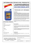
Before Change
After Change
The shape of the yellow part has been changed.
Copyright-2010 Toshiba America Business Solutions, Inc. (TABS). This publication contains proprietary and confidential
information retained for reference purpose by authorized TABS dealers. Unauthorized use of this information is prohibited.
TABS makes no express or implied warranty, including implied warranties of merchantability for a particular purpose, with regard
to this technical publication and disclaims any claim arising by reason of the possession or use thereof.
Before Change
[Changed/Added Part No.]
MODEL
P-I
After Change
Before Change
After Change
31-32
6LH55289000
FILM-STAY-THMIS-HR
---
31-35
---
6LH55306000
ASYS-STAY-THMIS-HR
205L/255/305/355/455
Note:
The original Stay was not available as a service part and due to this change, the film (P-I: 31-32)
has been discontinued as a service part since it has become a sub assembly part of the new
Stay.
Replacing Stay
Refer to the following procedures when replacing the Stay with a new one.
1. Remove the fuser roller (Section 12.6 of the Service Manual).
2. Remove the screws that hold the center, side and edge thermistors (Section 12.6.6 of the
Service Manual).
3. Remove the fuser center and front thermostats (Section 12.6.7 of the Service Manual).
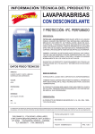
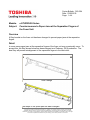
4. Remove 2 screws (red arrows in the illustration below), and take off the Stay ("A" in the
illustration below).
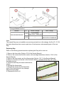
5. Install the new Stay and secure with the two
screws
6. Reinstall the thermostats
7. Reinstall the screws for the thermistors
Note: Check thermistors for any damage.
See photos next page.
8. Reassemble fuser unit
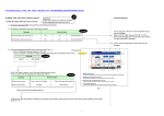
Checking of Thermistors:
Be sure to check the thermistors when reassembling the fuser unit. If the thermistor is deformed
replace the thermistor.
Thermistor deformed
Thermistor normal
Change of Fuser USP Part Number
Due to the change of the Stay the Fuser USP has been changed.
Note: The complete fuser unit does not need to be changed to install the Stay.
[Changed/Added Part No.]
MODEL
P-I
Before Change
After Change
104-1A
6LH55296000
FUSER-3000-115
6LH55311000
FUSER-3000-115
104-1B
6LH55296100
FUSER-3000-220
6LH55311100
FUSER-3000-220
104-1C
6LH55297000
FUSER-4530-115
6LH55312000
FUSER-4530-115
104-1D
6LH55297100
FUSER-4530-220
6LH55312100
FUSER-4530-220
205L/255/305/355/455
To identify the new fuser unit, refer to the serial number indicated as shown below.
10: 2010 (year)
02: February (month)
01: 1st (day)
Copier Bulletin: DIG-304
Date: 3/2/2010
TOSHIBA
ELECTRONIC IMAGING DIVISION
6LH55306000
ASYS-STAY-THMIS-HR
Dealer Name
Dealer Number
Address
Phone Number
City, St., Zip
Fax Number
Name & Title
Contact Name
Contact Email
Sales Order #
---This offer is valid until May 31, 2010 --This form is used to release the order for the designated part. When using this form, dealers
will NOT be charged for the specified part.
Part Number
6LH55306000
Part Name
ASYS-STAY-THMIS-HR
Quantity Requested
____________ (place order online)
Place your orders for this item online as you would for any other part. Once your order is placed,
please send this form to Toshiba National Parts. When Toshiba National Parts receives this form
we will retrieve your order on FYI, and release your order.
Send this form to Toshiba Parts Team in Irvine, CA
(800) 999-0057 [Domestic] (949) 588-0158 [International]
or email [email protected]

![2 Appuyez sur la touche [FAX] du tableau de bord.](http://vs1.manualzilla.com/store/data/006377769_1-cb8366605658d2e9e5d72496d9b1e196-150x150.png)