1
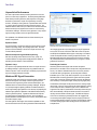
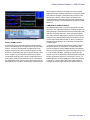
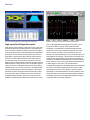
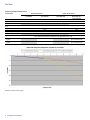
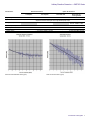
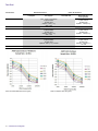
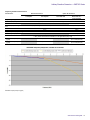
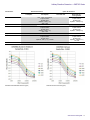
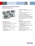
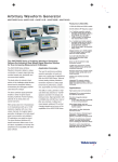
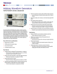
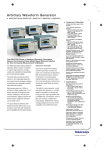
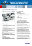
Arbitrary Waveform Generators
AWG7000 Series Data Sheet
Vertical Resolution up to 10 bit Available
Generate Signals up to 1 GHz Wide with 54 dBc SFDR
Deep Memory
Enables the Creation of Long Complex Waveform Sequences
Intuitive User Interface Shortens Test Time
Integrated PC supports Network Integration and provides a Built-in DVD,
Removable Hard Drive, LAN, eSATA, and USB Ports
Playback of Oscilloscope and Real-time Spectrum Analyzer Captured
Signals, including Enhancements such as Adding Predistortion Effects
Waveform Vectors Imported from Third-party Tools such as MathCAD,
MATLAB, Excel, and Others
Applications
Features & Benefits
Wideband RF/MW Modulation Bandwidth
Generates Complex Wideband Signals across a Frequency Range of
Up to 9.6 GHz
Generates Modulation Bandwidths of Up to 3.5 GHz (1 dB)
Waveform Sequencing and Subsequencing
Enables Creation of Infinite Waveform Loops, Jumps, and Conditional
Branches
Enhance the Ability to Replicate Real-world Signal Behavior
Dynamic Jump Capability
Enables the Creation of Complex Waveforms that Respond to
Changing External Environments
Wideband RF/MW for Communications and Defense Electronics
Wideband Direct RF/MW Output up to 9.6 GHz Carrier
High-speed Serial Communications
Up to 6 Gb/s Data Rate for Complex Serial Data Streams (4x
Oversampling, Interleaved)
Provides any Profile Multilevel Signals to allow Timing (Jitter) Margin
Testing without External Power Combiners
Mixed-signal Design and Test
2-channel Analog plus 4-channel Marker Outputs
High-speed, Low-jitter Data/Pulse and Clock Source
Real-world, Ideal, or Distorted Signals – Generates Any Combination of
Signal Impairments Simultaneously
Data Sheet
Unparalleled Performance
The need for performance arbitrary waveform generation is broad and
spans over a wide array of applications. The industry-leading AWG7000
Series arbitrary waveform generators (AWG) represent a cutting edge
benchmark in performance, sample rate, signal fidelity, and timing
resolution. The ability to create, generate, or replicate either ideal, distorted,
or “real-life” signals is essential in the design and testing process. The
AWG7000 Series of AWGs, with up to 24 GS/s and 10-bit vertical resolution,
delivers the industry’s best signal stimulus solution for ever-increasing
measurement challenges. This allows for easy generation of very complex
signals, including complete control over signal characteristics.
The capabilities of the AWG7000 Series are further enhanced by the
addition of key features:
Equation Editor
The Equation Editor is an ASCII text editor that uses text strings to create
waveforms by loading, editing, and compiling equation files. The editor
provides control and flexibility to create more complex waveforms using
customer-defined parameters.
Waveform Sequencing and Subsequencing
Real-time sequencing creates infinite waveform loops, jumps, and
conditional branches for longer pattern-length generation suitable for
replicating real-world behavior of serial transmitters.
Dynamic Jump
The Dynamic Jump capability enables the creation of complex waveforms
by enabling the ability to dynamically jump to any predefined index in a
waveform sequence. Users can define up to 256 distinct jump indexes that
respond to changing external environments.
Wideband RF Signal Generation
Creating RF signals is becoming more and more complex, making it more
difficult for RF engineers to accurately create the signals required for
conformance and margin testing. When combined with RFXpress, the
AWG7000 Series can address these tough design challenges. RFXpress
is a software package that digitally synthesizes modulated baseband, IF,
and RF signals taking signal generation to new levels by fully exploiting the
wideband signal generation capabilities of the AWG7000 Series arbitrary
waveform generators (AWGs). Together the AWG7000 and RFXpress
provide engineers with “bandwidth on demand”, which is the ability to
generate wideband modulated signals up to 3.5 GHz (1 dB) anywhere within
the 9.6 GHz frequency range.
The latest digital RF technologies often exceed the capabilities of other
test instruments because of the need to generate the wide-bandwidth and
2
www.tektronix.com/awg7000
AWG radar pulses created with AWG7000 and RFXpress.
fast-changing signals that are increasingly seen in many RF applications
such as radar, RF comms, OFDM, and UWB. When used in conjunction
with RFXpress the AWG7000 Series supports a wide range of modulation
formats and simplifies the task of creating complex RF waveforms. The
AWG7000 Series instruments provide customers with ways to generate
fully modulated baseband, intermediate frequency (IF) signals, or directly
generated RF waveforms.
Radar Signal Creation
Generating advanced radar signals often demands exceptional
performance from an AWG in terms of sample rate, analog bandwidth, and
memory. The Tektronix AWG7000 Series sets a new industry standard
for advanced radar signal generation, by delivering wide modulation
bandwidths up to 3.5 GHz (1 dB). With a sample rate of up to 24 GS/s the
AWG7000 Series can directly generate RF signals never before possible
from an AWG. In instances where IQ generation is desired, the AWG7000
offers the ability to oversample the signal, thereby improving signal quality.
The AWG7000 and RFXpress are the perfect solution for creating complex
radar signals. Customers are provided with the ultimate flexibility in creating
custom radar pulse suites. Modulation types such as LFM,Barker and
Polyphase Codes, Step FM, and Nonlinear FM are easily created using the
AWG, and the flexibility of RFXpress enables the creation of waveforms
requiring customer-defined modulation types. The AWG and RFXpress
combo also has the ability to generate pulse trains with staggered PRI
to resolve range and doppler ambiguity, frequency hopping for Electronic
Counter-Counter Measures (ECCM), and pulse-to-pulse amplitude variation
to simulate Swerling target models including antenna scan patterns and
multipath effects.
Arbitrary Waveform Generators — AWG7000 Series
ability to define each subcarrier in the symbol which can be configured
independently for type, modulation, and base data. The RFXpress software
gives visibility into all aspects of the OFDM signal by providing a symbol
table that gives a summary of all the carriers in the selected symbol.
OFDM packets/frames can be built by specifying the spacing between the
symbols/frames and parts of the OFDM packets can be stressed by adding
gated noise.
Direct WiMedia signals are easily created with the AWG7000 and RFXpress.
Generic OFDM Creation
In today’s wireless world, OFDM is becoming the modulation method of
choice for transmitting large amounts of digital data over short and medium
distances. The need for wide bandwidths and multiple carriers create
challenges for engineers who need to create OFDM signals to test their
RF receivers. The AWG7000 Series, when coupled with RFXpress, allows
users to configure every part of the OFDM signal definition. Engineers
can build signals symbol-by-symbol to create a complete OFDM frame or
let the RFXpress software choose default values for some signal aspects.
The AWG/RFXpress combo supports a variety of data coding formats that
include Reed Solomon, Convolution, and Scrambling. Users also have the
UWB-WiMedia (UWBCF/UWBCT)
Ultra-Wideband (UWB) wireless is a growing technology that is designed
for low-power, short-range wireless applications. UWB has emerged as the
leading technology for applications like wireless Universal Serial Bus (USB).
UWB radios, like generic OFDM radios, require wide signal bandwidths
and multiple carriers, but UWB designs also require short-duration pulses
and transmit Power Spectral Densities (PSDs) near the thermal noise floor
which can make creating UWB test signals very difficult. Fortunately, the
AWG7000 Series and RFXpress offer a solid solution for the generation
of UWB test signals.
The AWG7000 and RFXpress have the capability to digitally synthesize
and generate signals in the UWB spectrum. For either custom UWB
signal or ones defined for the latest WiMedia specification, the AWG7000
solution can recreate signals that are required to band hop in real time over
a 1.6 GHz modulation bandwidth. The RFXpress software gives users
complete control over the characteristics of their UWB signals including the
preamble synchronization sequences, cover sequences, and TFCs. For
WiMedia applications all six band groups (BG1 to BG6) can be generated
in either IQ, IF, or direct RF signals, giving users 3 different options for
creating/up-converting the signals when using an AWG7000 instrument.
www.tektronix.com/awg7000
3
Data Sheet
Easily create digital data impairments with the AWG7000 and SerialXpress.
Digital data with de-emphasis added using the AWG7000 and SerialXpress.
High-speed Serial Signal Generation
aspect of their digital signals reaching speeds of up to 6 Gb/s. This is
exactly what is needed for rigorous receiver testing requirements.
Serial signals are made up entirely of simple ones and zeros – binary data.
Historically engineers have used data generators to create digital signals.
As clock rates have increased these simple ones and zeros have begun to
look more like analog waveforms because embedded in the digital data are
analog events. The zero rise time and the perfectly flat tops of textbook
digital signals no longer represent reality. Electronic environments have
noise, jitter, crosstalk, distributed reactances, power supply variations,
and other shortcomings. Each takes its toll on the signal. A real-world
digital “square wave” rarely resembles its theoretical counterpart. Since the
AWG7000 Series is an analog waveform source it is the perfect single-box
solution that is used to create digital data streams and mimic the analog
imperfections that occur in real-world environments. The AWG7000 Series
uses direct synthesis techniques which allow engineers to create signals
that embody the effects of propagation through a transmission line. Rise
times, pulse shapes, delays, and aberrations can all be controlled with
the AWG7000 Series instruments. When used in conjunction with the
SerialXpress software package, engineers are provided control over every
4
www.tektronix.com/awg7000
SerialXpress is an integrated SW tool that enables AWG7000 Series
instruments to create a variety of digital data impairments such as jitter
(Random, Periodic, Sinusoidal), noise, pre/de-emphasis, duty cycle
distortion, Inter-symbol Interference (ISI), Duty Cycle Distortion (DCD), and
Spread Spectrum Clocking (SSC). The transmission environments of both
board and cables can be emulated using touchstone files uploaded into
SerialXpress. The AWG7000 and SerialXpress solution also provides base
pattern waveforms for many of today’s high-speed serial applications such
as SATA, Display Port, SAS, PCI-E, USB, and Fibre Channel.
For high-speed serial applications the AWG7000 Series offers the industry’s
best solution for addressing challenging signal stimulus issues faced by
digital designers who need to verify, characterize, and debug complex
digital designs. The file-based architecture uses direct synthesis to create
complex data streams and provides users with the simplicity, repeatability,
and flexibility required to solve the toughest signal generation challenges
in high-speed serial communication applications.
Arbitrary Waveform Generators — AWG7000 Series
Characteristics
Definitions
Specifications (not noted) – Product characteristics described in terms of specified performance with tolerance limits which are warranted/guaranteed to the customer.
Specifications are checked in the manufacturing process and in the Performance Verification section of the product manual with a direct measurement of the parameter.
Typical (noted) – Product characteristics described in terms of typical performance, but not guaranteed performance. The values given are never warranted, but most units
will perform to the level indicated. Typical characteristics are not tested in the manufacturing process or the Performance Verification section of the product manual.
Nominal (noted) – Product characteristics described in terms of being guaranteed by design. Nominal characteristics are non-warranted, so they are not checked in the
manufacturing process or the Performance Verification section of the product manual.
AWG7122C Series Specifications
General Characteristics
Characteristic
Standard Instrument
Normal:
w/ Amplifier
Digital to Analog Converter
Sample rate (nominal)
Resolution (nominal)
Sin (x)/x Roll-off
Sin (x)/x (–1 dB)
Sin (x)/x (–3 dB)
Option 06 Instrument
Direct:
w/o Amplifier
Wideband:
Direct DAC Out
10 MS/s to 12 GS/s (2 Ch)
10 bit (no markers selected) or 8 bit (markers selected)
3.1 GHz
5.3 GHz
Interleave:
Direct DAC Out –
Zeroing On/Off
12 GS/s to 24 GS/s (1 Ch)
6.2 GHz
10.6 GHz
www.tektronix.com/awg7000
5
Data Sheet
Frequency Domain Characteristics
Characteristic
Standard Instrument
Normal:
w/ Amplifier
Option 06 Instrument
Direct:
w/o Amplifier
Wideband:
Direct DAC Out
Interleave:
Direct DAC Out –
Zeroing On/Off
Output Frequency Characteristics
Effective Frequency Output
Fmaximum
Effective Frequency Switching
Time
Standard
Switching time (Ts)
Option 08 (fast frequency switching)
Switching time (Ts)
Modulation Bandwidth
Mod bandwidth (–1 dB)
(typical)
Mod bandwidth (–3 dB)
(typical)
AWG7122C Frequency Response (typical).
6
www.tektronix.com/awg7000
Fmaximum (specified) is determined as "sample rate / oversampling rate" or "SR / 2.5"
4.8 GHz
9.6 GHz
Minimum frequency switching time from selected frequencies F1 to F2 is determined as "1/Fmaximum", Option 08 only
106 μs
106 μs
208 ps
104 ps
Modulation bandwidth is determined as a combination of Sin (x)/x roll-off and rise-time bandwidth collectively corrected to
<1 dB by external measurement and calibration over the applicable frequency range
Up to 420 MHz
Up to 1.7 GHz
Up to 2.5 GHz
Up to 3.5 GHz (Zero On)
Up to 2.5 GHz (Zero Off)
Up to 740 MHz
Up to 2.9 GHz
Up to 4.3 GHz
Up to 6.2 GHz (Zero On)
Up to 4.3 GHz (Zero Off)
Arbitrary Waveform Generators — AWG7000 Series
Characteristic
Standard Instrument
Normal:
Direct:
w/ Amplifier
w/o Amplifier
Option 06 Instrument
Wideband:
Interleave:
Direct DAC Out
Direct DAC Out –
Zeroing On/Off
Output Amplitude Characteristics
Amplitude
Range (nominal)
Resolution (nominal)
Accuracy
Output Flatness
Flatness (typical)
Amplitude levels are measured as single-ended outputs
Amplitude level will be 3 dBm higher when using differential (both) outputs
–22 dBm to 10 dBm
–22 dBm to 4 dBm
–2 dBm to 4 dBm
Zero On: –2 dBm to 4 dBm
Zero Off: –8 dBm to –2 dBm
0.01 dB
At –2 dBm level, with no offset, ±0.3 dB
Mathematically corrected for characteristic Sin (x)/x roll-off, uncorrected by external calibration methods
±1.0 dB, from 50 MHz to 4.8 GHz
±2.5 dB, from 50 MHz to 9.6 GHz
AWG7122C Standard/Wideband Flatness (typical).
AWG7122C Interleave Flatness (typical).
www.tektronix.com/awg7000
7
Data Sheet
Time Domain Characteristics
Characteristic
Standard Instrument
Normal:
w/ Amplifier
Direct:
w/o Amplifier
Option 06 Instrument
Wideband:
Direct DAC Out
Interleave:
Direct DAC Out –
Zeroing On/Off
Data Rate Characteristics
Data Rate
Bit rate (nominal)
Bit rate determined as "sample rate / 4 points per cycle", allowing full impairment generation
3 Gb/s
6 Gb/s
Rise/Fall Time Characteristics
Rise/Fall Time
Tr/Tf (typical)
Rise Time Bandwidth
Tr bandwidth (–1 dB) (typical)
Tr bandwidth (–3 dB) (typical)
Low-pass filter
Rise/Fall time measured at 20% to 80% levels, related by a factor of 0.75 to the industry standard of 10% to 90% levels
75 ps
350 ps
35 ps
42 ps
Rise-time bandwidth converted from rise-time (0.26/Tr, assumed Gaussian transition) characteristics
through analog output circuitry and cabling
430 MHz
2.0 GHz
4.3 GHz
3.6 GHz
750 MHz
3.5 GHz
7.5 GHz
6.2 GHz
Bessel Type: 50 and 200 MHz
Output Amplitude Characteristics
Amplitude
Range (nominal)
Resolution (nominal)
Accuracy
Offset
Range (nominal)
Resolution (nominal)
Accuracy
8
www.tektronix.com/awg7000
Amplitude levels are measured between differential outputs (+) to (–)
For single-ended output the amplitude level will be one-half the voltage levels below
100 mVp-p to 4.0 Vp-p
100 mVp-p to 2.0 Vp-p
1.0 Vp-p to 2.0 Vp-p
Zero On: 1.0 Vp-p to 2.0 Vp-p
Zero Off: 500 mVp-p to 1.0 Vp-p
1.0 mV
At 0.5 V, with no offset, ±(3% of amplitude ±2 mV)
Zero On: ±(4% of level ±2 mV)
Zero Off: ±(8% of level ±2 mV)
±0.5 V
1.0 mV
At minimum amplitude, ±(2.0%
of offset ±10 mV)
Arbitrary Waveform Generators — AWG7000 Series
Common Characteristics
Characteristic
Standard Instrument
Normal:
w/ Amplifier
Direct:
w/o Amplifier
Option 06 Instrument
Wideband:
Direct DAC Out
Interleave:
Direct DAC Out –
Zeroing On/Off
Output Distortion Characteristics
Spurious Free Dynamic Range
(SFDR)
SFDR (typical)
DC to 1.0 GHz carrier
1.0 to 2.4 GHz carrier
2.4 to 3.5 GHz carrier
3.5 to 4.8 GHz carrier
4.8 to 9.6 GHz carrier
Spurious Free Dynamic Range
(SFDR)
SFDR (typical)
DC to 1.0 GHz bandwidth
DC to 2.4 GHz bandwidth
DC to 3.5 GHz bandwidth
SFDR is determined as a function of the directly generated carrier frequency. Harmonics not included
Clock: 12 GS/s, 10-bit operation
Frequency: 50 MHz to 4.8 GHz
Level: 4 dBm (1 Vp-p)
Offset: None
–54 dBc
–46 dBc
–38 dBc
–30 dBc
Clock: 24 GS/s, 10-bit operation
Frequency: 50 MHz to 9.6 GHz
Level: –2 dBm (0.5 Vp-p)
–54 dBc
–46 dBc
–38 dBc
–30 dBc
–26 dBc
When viewed as a modulation bandwidth and used with external frequency up-conversion, the specifications will hold and be
independent of carrier frequency with proper conversion circuitry design. Harmonics not included
Clock: 24 GS/s, 10-bit operation
Clock: 12 GS/s, 10-bit operation
Modulation Bandwidth: Up
Modulation Bandwidth: Up to 2.5 GHz
to 3.5 GHz
Level: 4 dBm (1 Vp-p)
Level: –2 dBm (0.5 Vp-p)
Offset: None
–54 dBc
–54 dBc
–46 dBc
–46 dBc
–38 dBc
–38 dBc
www.tektronix.com/awg7000
9
Data Sheet
Characteristic
Standard Instrument
Normal:
Direct:
w/ Amplifier
w/o Amplifier
Harmonic Distortion
Harmonics
Nonharmonic Distortion
< –35 dBc
Spurious
Phase Noise Distortion
Phase Noise
AWG7112C Standard/Wideband Phase Noise (typical).
10
www.tektronix.com/awg7000
Option 06 Instrument
Wideband:
Interleave:
Direct DAC Out
Direct DAC Out –
Zeroing On/Off
Clock: 12 GS/s, 10-bit operation
32-point waveform
375 MHz output
Amplitude: 4 dBm (1 Vp-p)
Offset: None
< –42 dBc
Clock: 12 GS/s, 10-bit operation
32-point waveform
375 MHz output
Amplitude: 4 dBm (1 Vp-p)
Offset: None
< –50 dBc
Clock: 12 GS/s, 10-bit operation
32-point waveform
375 MHz output
Amplitude: 4 dBm (1 Vp-p) at 0 offset
< –90 dBc/Hz at 10 kHz offset
AWG7112C Interleave Phase Noise (typical).
Clock: 24 GS/s, 10-bit operation
32-point waveform
750 MHz output
Amplitude: –2 dBm (0.5 Vp-p)
< –40 dBc
Clock: 24 GS/s, 10-bit operation
32-point waveform
750 MHz output
Amplitude: –2 dBm (0.5 Vp-p)
< –45 dBc
Clock: 24 GS/s, 10-bit operation
32-point waveform
750 MHz output
Amplitude: –2 dBm (0.5 Vp-p)
at 0 offset
< –85 dBc/Hz at 10 kHz offset
Arbitrary Waveform Generators — AWG7000 Series
Characteristic
Jitter
Random jitter (typical)
RMS value
Total jitter (typical)
P-P value
Standard Instrument
Normal:
Direct:
w/ Amplifier
w/o Amplifier
Option 06 Instrument
Wideband:
Interleave:
Direct DAC Out
Direct DAC Out –
Zeroing On/Off
1010 clock pattern
1.6 ps
50 ps at 0.5 Gb/s
0.9 ps
215 – 1 data pattern (at 10–12 BER)
30 ps at 3 Gb/s
20 ps from 2 to 6 Gb/s
Output Pulse Characteristics
Pulse Response
Tr/Tf (typical)
Timing skew (typical)
Delay from marker output
(typical)
Interleave skew adjustment
(typical)
Interleave level adjustment
(typical)
350 ps
75 ps
35 ps
<20 ps (between each channel) (+) Pos and (–) Neg outputs
50 MHz: 9.7 ns
200 MHz: 3.9 ns
2.1 ns
0.5 ns
42 ps
<12 ps (between each channel)
(+) Pos and (–) Neg outputs
0.9 ns
Skew adjust: ±180 degree
against sample rate (e.g.
24 GS/s: 83 ps = 360 degrees
with 0.1 degree resolution)
Level adjust: 1 mV resolution
www.tektronix.com/awg7000
11
Data Sheet
Definitions
Specifications (not noted) – Product characteristics described in terms of specified performance with tolerance limits which are warranted/guaranteed to the customer.
Specifications are checked in the manufacturing process and in the Performance Verification section of the product manual with a direct measurement of the parameter.
Typical (noted) – Product characteristics described in terms of typical performance, but not guaranteed performance. The values given are never warranted, but most units
will perform to the level indicated. Typical characteristics are not tested in the manufacturing process or the Performance Verification section of the product manual.
Nominal (noted) – Product characteristics described in terms of being guaranteed by design. Nominal characteristics are non-warranted, so they are not checked in the
manufacturing process or the Performance Verification section of the product manual.
AWG7082C Series Specifications
General Characteristics
Characteristic
Standard Instrument
Normal:
w/ Amplifier
Digital to Analog Converter
Sample rate (nominal)
Resolution (nominal)
Sin (x)/x Roll-off
Sin (x)/x (–1 dB)
Sin (x)/x (–3 dB)
12
www.tektronix.com/awg7000
Option 06 Instrument
Direct:
w/o Amplifier
Wideband:
Direct DAC Out
10 MS/s to 8 GS/s (2 Ch)
10 bit (no markers selected) or 8 bit (markers selected)
2.0 GHz
3.5 GHz
Interleave:
Direct DAC Out –
Zeroing On/Off
8 GS/s to 16 GS/s (1 Ch)
4.0 GHz
7.0 GHz
Arbitrary Waveform Generators — AWG7000 Series
Frequency Domain Characteristics
Characteristic
Standard Instrument
Normal:
w/ Amplifier
Option 06 Instrument
Direct:
w/o Amplifier
Wideband:
Direct DAC Out
Interleave:
Direct DAC Out –
Zeroing On/Off
Output Frequency Characteristics
Effective Frequency Output
Fmaximum
Effective Frequency Switching
Time
Standard
Switching time (Ts)
Option 08 (fast frequency switching)
Switching time (Ts)
Modulation Bandwidth
Mod bandwidth (–1 dB)
(typical)
Mod bandwidth (–3 dB)
(typical)
Fmaximum (specified) is determined as "sample rate / oversampling rate" or "SR / 2.5"
3.2 GHz
6.4 GHz
Minimum frequency switching time from selected frequencies F1 to F2 is determined as "1/Fmaximum", Option 08 only
8.0 ns
160 μs
313 ps
156 ps
Modulation bandwidth is determined as a combination of Sin (x)/x roll-off and rise-time bandwidth collectively corrected to
<1 dB by external measurement and calibration over the applicable frequency range
Up to 420 MHz
Up to 1.4 GHz
Up to 1.9 GHz
Up to 3.0 GHz (Zero On)
Up to 1.9 GHz (Zero Off)
Up to 740 MHz
Up to 2.5 GHz
Up to 3.2 GHz
Up to 5.2 GHz (Zero On)
Up to 3.2 GHz (Zero Off)
AWG7082C Frequency Response (typical).
www.tektronix.com/awg7000
13
Data Sheet
Characteristic
Standard Instrument
Normal:
Direct:
w/ Amplifier
w/o Amplifier
Option 06 Instrument
Wideband:
Interleave:
Direct DAC Out
Direct DAC Out –
Zeroing On/Off
Output Amplitude Characteristics
Amplitude
Range (nominal)
Resolution (nominal)
Accuracy
Output Flatness
Flatness (typical)
Amplitude levels are measured as single-ended outputs
Amplitude level will be 3 dBm higher when using differential (both) outputs
–22 dBm to 10 dBm
–22 dBm to 4 dBm
–2 dBm to 4 dBm
Zero On: –2 dBm to 4 dBm
Zero Off: –8 dBm to –2 dBm
0.01 dB
At –2 dBm level, with no offset, ±0.3 dB
Mathematically corrected for characteristic Sin (x)/x roll-off, uncorrected by external calibration methods
±1.0 dB, from 50 MHz to 3.2 GHz
±2.5 dB, from 50 MHz to 6.4 GHz
AWG7082C Standard/Wideband Flatness (typical).
14
www.tektronix.com/awg7000
AWG7082C Interleave Flatness (typical).
Arbitrary Waveform Generators — AWG7000 Series
Time Domain Characteristics
Characteristic
Standard Instrument
Normal:
w/ Amplifier
Direct:
w/o Amplifier
Option 06 Instrument
Wideband:
Direct DAC Out
Interleave:
Direct DAC Out –
Zeroing On/Off
Data Rate Characteristics
Data Rate
Bit rate (nominal)
Bit rate determined as "sample rate / 4 points per cycle", allowing full impairment generation
2 Gb/s
4 Gb/s
Rise/Fall Time Characteristics
Rise/Fall Time
Tr/Tf (typical)
Rise-time Bandwidth
Tr bandwidth (–1 dB) (typical)
Tr bandwidth (–3 dB) (typical)
Low-pass filter
Rise/Fall time measured at 20% to 80% levels, related by a factor of 0.75 to the industry standard of 10% to 90% levels
75 ps
350 ps
35 ps
42 ps
Rise-time bandwidth converted from rise-time (0.26/Tr, assumed Gaussian transition) characteristics
through analog output circuitry and cabling
430 MHz
2.0 GHz
4.3 GHz
3.6 GHz
750 MHz
3.5 GHz
7.5 GHz
6.2 GHz
Bessel Type: 50 and 200 MHz
Output Amplitude Characteristics
Amplitude
Range (nominal)
Resolution (nominal)
Accuracy
Offset
Range (nominal)
Resolution (nominal)
Accuracy
Amplitude levels are measured between differential outputs (+) to (–)
Single-ended output amplitude level will be one-half the voltage levels below
100 mVp-p to 4.0 Vp-p
100 mVp-p to 2.0 Vp-p
1.0 Vp-p to 2.0 Vp-p
Zero On: 1.0 Vp-p to 2.0 Vp-p
Zero Off: 500 mVp-p to 1.0 Vp-p
1.0 mV
At 0.5 V, with no offset, ±(3% of amplitude ±2 mV)
Zero On: ±(4% of level ±2 mV)
Zero Off: ±(8% of level ±2 mV)
±0.5 V
1.0 mV
At minimum amplitude, ±(2.0%
of offset ±10 mV)
www.tektronix.com/awg7000
15
Data Sheet
Common Characteristics
Characteristic
Standard Instrument
Normal:
w/ Amplifier
Direct:
w/o Amplifier
Option 06 Instrument
Wideband:
Direct DAC Out
Interleave:
Direct DAC Out –
Zeroing On/Off
Output Distortion Characteristics
Spurious Free Dynamic Range
(SFDR)
SFDR (typical)
DC to 1.0 GHz carrier
1.0 to 2.4 GHz carrier
2.4 to 3.5 GHz carrier
3.5 to 4.8 GHz carrier
4.8 to 6.4 GHz carrier
Spurious Free Dynamic Range
(SFDR)
SFDR (typical)
DC to 1.0 GHz bandwidth
DC to 2.4 GHz bandwidth
DC to 3.5 GHz bandwidth
16
www.tektronix.com/awg7000
SFDR is determined as a function of the directly generated carrier frequency. Harmonics not included
Clock: 12 GS/s, 10-bit operation
Frequency: 50 MHz to 3.2 GHz
Level: 4 dBm (1 Vp-p)
Offset: None
–54 dBc
–46 dBc
–40 dBc
Clock: 24 GS/s, 10-bit operation
Frequency: 50 MHz to 6.4 GHz
Level: –2 dBm (0.5 Vp-p)
–54 dBc
–46 dBc
–40 dBc
–32 dBc
–28 dBc
When viewed as a modulation bandwidth and used with external frequency up-conversion, the specifications will hold and be
independent of carrier frequency with proper conversion circuitry design. Harmonics not included
Clock: 16 GS/s, 10-bit operation
Clock: 8 GS/s, 10-bit operation
Modulation Bandwidth: Up
Modulation Bandwidth: Up to 1.9 GHz
to 3.0 GHz
Level: 4 dBm (1 Vp-p)
Level: –2 dBm (0.5 Vp-p)
Offset: None
–54 dBc
–54 dBc
–46 dBc
–46 dBc
–40 dBc
Arbitrary Waveform Generators — AWG7000 Series
Characteristic
Standard Instrument
Normal:
Direct:
w/ Amplifier
w/o Amplifier
Harmonic Distortion
Harmonics
Nonharmonic Distortion
< –35 dBc
Spurious
Phase Noise Distortion
Phase Noise
AWG7082C Standard/Wideband Phase Noise (typical).
Option 06 Instrument
Wideband:
Interleave:
Direct DAC Out
Direct DAC Out –
Zeroing On/Off
Clock: 8 GS/s, 10-bit operation
32-point waveform
250 MHz output
Amplitude: 4 dBm (1 Vp-p)
Offset: None
< –42 dBc
Clock: 8 GS/s, 10-bit operation
32-point waveform
250 MHz output
Amplitude: 4 dBm (1 Vp-p)
Offset: None
< –50 dBc
Clock: 8 GS/s, 10-bit operation
32-point waveform
250 MHz output
Amplitude: 4 dBm (1 Vp-p) at 0 offset
< –90 dBc/Hz at 10 kHz offset
Clock: 16 GS/s, 10-bit operation
32-point waveform
500 MHz output
Amplitude: –2 dBm (0.5 Vp-p)
< –40 dBc
Clock: 16 GS/s, 10-bit operation
32-point waveform
500 MHz output
Amplitude: –2 dBm (0.5 Vp-p)
< –45 dBc
Clock: 16 GS/s, 10-bit operation
32-point waveform
500 MHz output
Amplitude: –2 dBm (0.5 Vp-p)
at 0 offset
< –85 dBc/Hz at 10 kHz offset
AWG7082C Interleave Phase Noise (typical).
www.tektronix.com/awg7000
17
Data Sheet
Characteristic
Jitter
Random jitter (typical)
RMS value
Total jitter (typical)
P-P value
Standard Instrument
Normal:
Direct:
w/ Amplifier
w/o Amplifier
Option 06 Instrument
Wideband:
Interleave:
Direct DAC Out
Direct DAC Out –
Zeroing On/Off
1010 clock pattern
1.6 ps
50 ps at 0.5 Gb/s
0.9 ps
215 – 1 data pattern (at 10–12 BER)
30 ps at 2 Gb/s
20 ps from 2 to 4 Gb/s
Output Pulse Characteristics
Pulse Response
Tr/Tf (typical)
Timing skew (typical)
Delay from marker output
(typical)
Interleave skew adjustment
(typical)
Interleave level adjustment
(typical)
18
www.tektronix.com/awg7000
350 ps
75 ps
35 ps
<20 ps (between each channel) (+) Pos and (–) Neg outputs
50 MHz: 9.7 ns
200 MHz: 3.9 ns
2.1 ns
0.5 ns
42 ps
<12 ps (between each channel)
(+) Pos and (–) Neg outputs
0.9 ns
Skew adjust: ±180 degree
against sample rate (e.g.
24 GS/s: 83 ps = 360 degrees
with 0.1 degree resolution)
Level adjust: 1 mV resolution
Arbitrary Waveform Generators — AWG7000 Series
AWG7000C Series Common Features
Common Hardware Characteristics
Characteristic
Standard Instrument
w/ Amplifier
Number of Outputs
Output connector
Output impedance (nominal)
Waveform Length
Number of Waveforms
Sequence Length/Counter
Run Modes
Continuous
Triggered
Gated
Sequence
Jump
Sampling Clock
Resolution
Accuracy
Internal Trigger Generator
Range
Resolution
Output Skew Control
Range
Resolution
Accuracy
w/o Amplifier
Option 06 Instrument
Wideband:
Interleave:
Direct DAC Out
Direct DAC Out –
Zeroing On/Off
2 channels, non-interleave
Differential, SMA (front panel)
50 Ω
Standard – to 32M points
Extended memory – to 64M points
2 channels, non-interleave
1 channel, interleave
Standard – to 64M points
Extended memory – to
128M points
1 to 16,200
1 to 16,000 steps, 1 to 65,536 count
Waveform is iteratively output. If a sequence is defined, the sequence order and repeat functions are applied
Waveform is output only once when an internal, external, programmatic (GPIB, LAN), or manual trigger is received
Waveform begins output when gate is "True" and resets when gate is "False"
Waveform is output as defined by the sequence selected
Synchronous and asynchronous
8 digits
Within ±(1 ppm + Aging), Aging: Within ±1 ppm per year
1.0 μs to 10.0 s
3 digits, 0.1 μs minimum
–100 to 100 ps
1 ps
±(10% of setting + 10 ps)
www.tektronix.com/awg7000
19
Data Sheet
Common Software Characteristics
Characteristic
Standard Instrument
w/ Amplifier
Operating System / Peripherals /
IO
Display Characteristics
Waveform File Import Capability
Waveform File Export Capability
Software Driver for Third-party
Applications
Instrument Control / Data Transfer
GPIB
Ethernet
TekLink
20
w/o Amplifier
Option 06 Instrument
Wideband:
Direct DAC Out
Interleave:
Direct DAC Out –
Zeroing On/Off
Windows 7
4 GB memory
160 GB hard disk drive (rear-panel removable, optional front mount kit)
CD/DVD drive (front panel)
Included USB compact keyboard and mouse
USB 2.0 compliant ports (6 total – 2 front, 4 rear)
PS/2 mouse and keyboard connections (rear panel)
RJ-45 Ethernet connector (rear panel) supports 10/100/1000BASE-T
DVI-I Video (rear panel) for external monitor
eSATA (rear panel)
LED backlit monitor with touch screen, 10.4 in. (264 mm) 1024 × 768 (V) XGA
Import waveform format by series:
*.AWG file created by Tektronix AWG5000 or AWG7000 Series
*.PAT, *.SEQ, *.WFM and *.EQU file formats created by Tektronix arbitrary waveform generators such as the AWG400/500/600/700 Series
*.IQT and *.TIQ files from Tektronix real-time spectrum analyzer
*.TFW file created by Tektronix AFG3000 Series arbitrary/function generators
*.DTG file created by Tektronix DTG5000 Series data timing generators
*.WFM or *.ISF file created by Tektronix TDS/DPO Series oscilloscopes text file (*.TXT)
Export waveform format by series:
Tektronix AWG400/500/600/700 (*.wfm or *.pat) and text format
IVI-COM driver, MATLAB library
www.tektronix.com/awg7000
Remote control and data transfer (conforms to IEEE-Std 488.1, compatible with IEEE-Std 488.2 and SCPI-1999.0)
Remote control and data transfer (conforms to IEEE-Std 802.3)
Remote control and data transfer (proprietary bus for Tektronix product high-speed interconnection and communication)
Arbitrary Waveform Generators — AWG7000 Series
Auxiliary Outputs
Characteristic
Standard Instrument
w/ Amplifier
Markers
Number
Style
Connector
Impedance
Level (into 50 Ω)
Window
Amplitude
Resolution
Accuracy
Rise/Fall time (20% to 80%)
Timing skew
Intra-skew (typical)
In-channel (typical)
Delay control
Range
Resolution
Accuracy
Jitter
Random RMS (typical)
Total p-p (typical)
10 MHz Reference Out
Amplitude
Connector
Impedance
DC Outputs
Number
Range
Resolution
Accuracy
Connector
Current (max)
Option 06 Instrument
w/o Amplifier
Wideband:
Direct DAC Out
Interleave:
Direct DAC Out –
Zeroing On/Off
Total: 4 (2 per channel)
Total: 2 (2 per channel)
Differential
SMA (front panel)
50 Ω
Amplitude levels are measured between differential outputs (+) to (–)
Single-ended output amplitude level will be one-half the voltage levels below
–2.8 V to 2.8 V
1.0 Vp-p to 2.8 Vp-p
10 mV
±(10% of setting + 75 mV)
45 ps (1.0 Vp-p, Hi: 1.0 V, Lo: 0.0 V)
<13 ps (between each channel (+) Pos and (–) Neg output)
<30 ps (between Marker 1 and Marker 2 outputs)
0 to 300 ps
1 ps
±(5% of setting + 50 ps)
1 ps
30 ps (215 – 1 PN pattern at 10–12 BER)
1.2 Vp-p into 50 Ω, maximum 2.5 V open
BNC (rear panel)
50 Ω, AC coupled
4, independently controlled
–3.0 to 5.0 V
10 mV
±(3% of setting + 120 mV)
2×4 pin header (front panel)
±30 mA
www.tektronix.com/awg7000
21
Data Sheet
Auxiliary Inputs
Characteristic
Standard Instrument
w/ Amplifier
Trigger / Gate In
Polarity
Range
Connector
Impedance
Threshold
Level
Resolution
Trigger to output uncertainty
Asynchronous (typical)
Synchronous (typical)
Synchronous (typical)
Synchronous (typical)
Interleave:
Direct DAC Out –
Zeroing On/Off
Pos or Neg
50 Ω: ±5 V, 1 kΩ: ±10 V
BNC (front panel)
50 Ω, 1 kΩ
–5.0 V to 5.0 V
0.1 V
Between internal/external clock and trigger timing: 0.5 ns at 12 GS/s, 0.7 ns at 10 GS/s, 0.8 ns at 9 GS/s, 0.9 ns at 8 GS/s, 1.0 ns at 6 GS/s
Between external clock and trigger timing: 12 GS/s, X1 clock divider, synchronous trigger mode with specific timing (120 psp-p, 30 psRMS)
Between external 10 MHz reference and trigger timing: 12 GS/s setting, synchronous trigger mode with specific timing (120 psp-p, 30 psRMS)
Between external variable reference and trigger timing: 2n (n: integer) clock reference, synchronous
trigger and specific timing (50 psp-p, 10 psRMS)
Trigger mode
Minimum pulse width
Trigger hold-off
Delay to output
Gated mode
Minimum pulse width
Delay to output
Dynamic Jump
Connector
Level
Impedance
Strobe
Event In
Polarity
Range
Connector
Impedance
Threshold
Level
Resolution
Sequence mode
Minimum pulse width
Event hold-off
Delay to output
22
Option 06 Instrument
Wideband:
Direct DAC Out
w/o Amplifier
www.tektronix.com/awg7000
20 ns
832 × sampling period – 100 ns
128 × sampling period + 250 ns
1024 × sampling period + 10 ns
640 × sampling period + 260 ns
15-pin DSUB on rear panel
TTL +5 V compliant inputs, 3.3 V LV CMOS level
Pull up to 3.3 V by 1 kΩ resistor
Must strobe jump destination
Pos or Neg
50 Ω: ±5 V, 1 kΩ: ±10 V
BNC (front panel)
50 Ω, 1 kΩ
–5.0 to 5.0 V
0.1 V
20 ns
900 × sampling period + 150 ns
1024 × sampling period + 280 ns (Jump timing: asynchronous jump)
Arbitrary Waveform Generators — AWG7000 Series
Characteristic
Standard Instrument
w/ Amplifier
w/o Amplifier
External Clock In
Input voltage range
Frequency range
Clock divider
Connector
Impedance
Fixed Reference Clock In
Input voltage range
Frequency range
Connector
Impedance
Variable Reference Clock In
Input voltage range
Frequency range
Multiplier rate
Connector
Impedance
1.4 Vp-p to 2.2 Vp-p, 7 dBm to 11 dBm
6 GHz to 12 GHz (acceptable frequency drift of ±0.1%)
1/1, 1/2, 1/4...1/256
SMA (rear panel)
50 Ω, AC coupled
0.2 Vp-p to 3.0 Vp-p
10 MHz, 20 MHz, 100 MHz (within ±0.1%)
BNC (rear panel)
50 Ω, AC coupled
0.2 Vp-p to 3.0 Vp-p
5 MHz to 800 MHz (acceptable frequency drift is ±0.1%)
1 to 2400
BNC (rear panel)
50 Ω, AC coupled
Physical Characteristics
2 to 4800
Environmental Characteristics
Dimension
mm
in.
Characteristic
Height
Width
Depth
245
465
500
9.6
18.0
19.7
Weight
kg
lb.
Net (instrument)
Net (with packaging)
19
28
41.9
61.7
Temperature
Operational
Nonoperational
Humidity
Operational
Mechanical Cooling
Clearance
cm
in.
Top/Bottom
Side
Rear
2
15
7.5
0.8
6
3
Power Supply
Rating
Consumption
Option 06 Instrument
Wideband:
Interleave:
Direct DAC Out
Direct DAC Out –
Zeroing On/Off
100 to 240 V AC, 47 to 63 Hz
450 Watts
Nonoperational
Altitude
Operational
Nonoperational
Vibration
Sine
Operational
Nonoperational
Random
Operational
Nonoperational
Mechanical Shock
Operational
Nonoperational
Regulatory
Safety
Description
10 to 40 °C
20 to 60 °C
5% to 80% relative humidity (% RH) at up to 30 °C, 5%
to 45% relative humidity above 30 °C up to 50 °C
5% to 90% relative humidity (% RH) at up to 30 °C, 5%
to 45% relative humidity above 30 °C up to 50 °C
Up to 10,000 ft. (3,048 m)
Up to 40,000 ft. (12,192 m)
0.33 mm p-p (0.013 in p-p) constant displacement, 5 to
55 Hz
NA
0.27 g RMS, 5 to 500 Hz, 10 minutes per axis
2.28 g RMS, 5 to 500 Hz, 10 minutes per axis
Half-sine mechanical shocks, 30 g peak, 11 ms duration,
3 drops in each direction of each axis
Half-sine mechanical shocks, 10 g peak, 11 ms duration,
3 drops in each direction of each axis
UL61010-1, CAN/CSA-22.2, No.61010-1-04,
EN61010-1, IEC61010-1
EN55011 (Class A), IEC61000-3-2, IEC61000-3-3
IEC61326, IEC61000-4-2/3/4/5/6/8/11
Emissions
Immunity
Regional certifications
Europe
EN61326
Australia / New
AS/NZS 2064
Zealand
www.tektronix.com/awg7000
23
Data Sheet
Ordering Information
Application Software
Arbitrary Waveform Generator
Product
Description
RFX100
General-purpose IQ, IF, and RF Signal Creation
Software Package
RFXpress plug-in for UWB-WiMedia IQ, IF, and RF
conformance signal creation
(requires RFX100 as prerequisite)
RFXpress plug-in for UWB-WiMedia IQ, IF, and RF
custom and conformance signal creation (requires
RFX100 as prerequisite and includes Opt. UWBCF)
RFXpress plug-in for generic OFDM signal creation
(requires RFX100 as prerequisite)
RFXpress plug-in for radar signal creation
(requires RFX100 as prerequisite)
S-parameter emulation and DUT characterization
(requires RFX100 as prerequisite)
Jitter-generation software package (includes USB
dongle)
S-parameter and ISI creation
(requires SDX100 as prerequisite)
Spread Spectrum Clock addition option
(requires SDX100 as prerequisite)
AWG7122C
12.0 GS/s (24 GS/s interleaved), 8/10 bit, 32M point, 2-channel arbitrary waveform
generator.
AWG7082C
8.0 GS/s (16 GS/s interleaved), 8/10 bit, 32M point, 2-channel arbitrary waveform
generator.
All Models Include: Accessory pouch, front cover, USB mouse, compact USB
keyboard, lead set for DC output, stylus for touch screen (2 ea), AWG7000C Series
product software CD and instructions, documentation CD with browser, Quick Start
User Manual and registration card, Certificate of Calibration, power cable, and 50 Ω
SMA terminator (3 ea).
Note: Please specify power cord and language option at time of order.
Opt. UWBCF
Opt. UWBCT
Opt. OFDM
Opt. RDR
Opt. SPARA
SDX100
Instrument Options
Opt. ISI
Product Options
Opt. SSC
Option
Opt. 01
Opt. 06
Opt. 08
Opt. 09
AWG7122C, AWG7082C
Waveform record length expansion
(from 32M point to 64M point)
Interleaved output at 24 GS/s (AWG7122C), 16 GS/s
(AWG7082C) (includes Option 02 – High-bandwidth
output), alternative for standard output (AWG7122C with
Option 06 requires export license)
Fast sequence switching (requires export license)
Subsequencing and Dynamic Jump option
(subsequencing files created for legacy AWG400,
AWG500, AWG600, and AWG700 instrument are
compatible with this option)
International Power Plugs
Option
Description
Opt.
Opt.
Opt.
Opt.
Opt.
Opt.
Opt.
Opt.
Opt.
North America
Universal EURO
United Kingdom
Australia
Switzerland
Japan
China
India
No power cord or AC adapter
A0
A1
A2
A3
A5
A6
A10
A11
A99
Language Options
Option
Description
Opt.
Opt.
Opt.
Opt.
Opt.
L0
L5
L7
L8
L10
English manual
Japanese manual
Simplified Chinese manual
Traditional Chinese manual
Russian manual
24
www.tektronix.com/awg7000
Service Options
Option
Description
Service Options (e.g. AWG7122C Opt. C3)
Opt. CA1
Opt. C3
Opt. C5
Opt. D1
Opt. D3
Opt. D5
Opt. R3
Opt. R5
A single calibration event
Calibration Service 3 Years
Calibration Service 5 Years
Calibration Data Report
Calibration Data Report 3 Years (with Opt. C3)
Calibration Data Report 5 Years (with Opt. C5)
Repair Service 3 Years
Repair Service 5 Years
Post Sales Service Options: (e.g. AWG7122C-CA1)
CA1
R3DW
R5DW
R2PW
R1PW
A single calibration event
Repair Service Coverage 3 Years
Repair Service Coverage 5 Years
Repair Service Coverage 2 Years Post Warranty
Repair Service Coverage 1 Year Post Warranty
Product Upgrade
Product
Ordering Options
AWG7122C
AWG7082C
AWG70CUP
AWG70CUP
Opt. M02
Opt. M01
AWG7122C
AWG7082C
AWG70CUP
AWG70CUP
Opt. S02
Opt. S01
AWG7122C
AWG7082C
AWG70CUP
AWG70CUP
Opt. S49
Opt. S29
Description
Waveform length
expansion 32M
point to 64M point
Upgrade from
Standard to Option
08 (fast sequence
switching), requires
export license
Upgrade to add
subsequencing and
dynamic jump
Arbitrary Waveform Generators — AWG7000 Series
Recommended Accessories
Item
Pin Header
SMA Cable
SMB Cable
Rackmount Kit
Front Removable HDD
Bay
Replacement Hard Disk
for AWG5000/7000 Series
Quick Start User Manual
Service Manual
Description
Parts Number
40 in. (102 cm)
20 in. (51 cm)
Rackmount Kit with
Instruction
Front Removable HDD
Bay
SATA disk assembly (no
software installation),
instruction sheet
English
Japanese
Simplified Chinese
Traditional Chinese
Russian
Service Manual, English
012-1690-xx
012-1503-xx
016-1983-xx
016-1979-xx
Warranty
One-year parts and labor.
Product(s) are manufactured in ISO registered facilities.
Product(s) complies with IEEE Standard 488.1-1987, RS-232-C, and with Tektronix
Standard Codes and Formats.
650-5336-xx
071-2481-xx
071-2482-xx
071-2483-xx
071-2484-xx
020-2971-xx
Visit Tektronix website
www.tektronix.com/awg7000
25
Data Sheet
26
www.tektronix.com/awg7000
Arbitrary Waveform Generators — AWG7000 Series
www.tektronix.com/awg7000
27
Data Sheet
Contact Tektronix:
ASEAN / Australasia (65) 6356 3900
Austria 00800 2255 4835*
Balkans, Israel, South Africa and other ISE Countries +41 52 675 3777
Belgium 00800 2255 4835*
Brazil +55 (11) 3759 7600
Canada 1 800 833 9200
Central East Europe, Ukraine, and the Baltics +41 52 675 3777
Central Europe & Greece +41 52 675 3777
Denmark +45 80 88 1401
Finland +41 52 675 3777
France 00800 2255 4835*
Germany 00800 2255 4835*
Hong Kong 400 820 5835
India 000 800 650 1835
Italy 00800 2255 4835*
Japan 81 (3) 6714 3010
Luxembourg +41 52 675 3777
Mexico, Central/South America & Caribbean (52) 56 04 50 90
Middle East, Asia, and North Africa +41 52 675 3777
The Netherlands 00800 2255 4835*
Norway 800 16098
People’s Republic of China 400 820 5835
Poland +41 52 675 3777
Portugal 80 08 12370
Republic of Korea 001 800 8255 2835
Russia & CIS +7 (495) 7484900
South Africa +41 52 675 3777
Spain 00800 2255 4835*
Sweden 00800 2255 4835*
Switzerland 00800 2255 4835*
Taiwan 886 (2) 2722 9622
United Kingdom & Ireland 00800 2255 4835*
USA 1 800 833 9200
* European toll-free number. If not accessible, call: +41 52 675 3777
Updated 25 May 2010
For Further Information. Tektronix maintains a comprehensive, constantly expanding
collection of application notes, technical briefs and other resources to help engineers working
on the cutting edge of technology. Please visit www.tektronix.com
Copyright © Tektronix, Inc. All rights reserved. Tektronix products are covered by U.S. and foreign patents,
issued and pending. Information in this publication supersedes that in all previously published material.
Specification and price change privileges reserved. TEKTRONIX and TEK are registered trademarks of
Tektronix, Inc. All other trade names referenced are the service marks, trademarks, or registered trademarks
of their respective companies.
06 Oct 2010
www.tektronix.com/awg7000
76W-22259-5