1
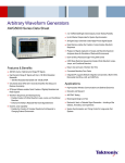
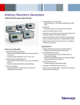
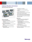
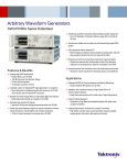
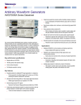
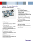
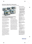
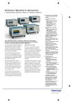
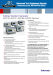
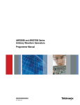
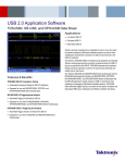
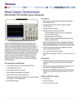
Arbitrary Waveform Generators
AWG5000 Series Data Sheet
2 or 4 Differential/Single-ended Outputs provide Testing Flexibility
Up to 8 Marker Outputs ideal for System Synchronization
28 Digital Output Channels Create Highly Precise Digital Signals
Deep Memory enables the Creation of Long Complex Waveform
Sequences
Playback of Signals Captured on Scopes and Real-time Spectrum
Analyzers allows for Simulation of Real-world Environments
Down to 800 ps Resolution Edge Timing Shift Control
8,000 Steps Real-time Sequencing Creates Infinite Waveform Loops,
Jumps, and Conditional Branches
Features & Benefits
Easy to Use and Learn, Shortens Test Time
480 MHz Carrier, High Dynamic Range RF Signals
Convenient Benchtop Form Factor
High Dynamic Range IF Signals with Up to 180 MHz Modulation
Bandwidth
180 MHz Modulation Bandwidth with –58 dBc SFDR
Integrated PC supports Network Integration and provides a Built-in DVD,
Removable Hard Drive, LAN, and USB Ports
Only Stand-alone AWG with 4 Channels Simplifies Test Setup and
Reduces Uncertainty
RFXpress Software enables Quick Creation of Digitally Modulated and
Radar Signals
Waveform Sequencing and Subsequencing
Enables Creation of Infinite Waveform Loops, Jumps, and Conditional
Branches
Enhance the Ability to Replicate Real-world Signal Behavior
Dynamic Jump Capability
Enables the Creation of Complex Waveforms that Respond to
Changing External Environment
Applications
High-resolution Wireless Communications and Defense Electronics
Education and Research
ADC/DAC Testing
Mixed-signal Design and Test
Real-world, Ideal, or Distorted Signal Generation – Including all the
Glitches, Anomalies, and Impairments
System Synchronization and Timing Control for Large-scale Test
Systems
Data Sheet
EVM/Constellation Measurement.
Mixed-signal test by TDS/TLA iView.
Industry’s Best Mixed-signal Stimulus
Solution for Today’s Complex Measurement
Challenges
Dynamic Jump
The Dynamic Jump capability enables the creation of complex waveforms
by enabling the ability to dynamically jump to any prede ned index in a
waveform sequence. Users can de ne up to 16 distinct jump indexes that
respond to changing external environments.
The AWG5000 Series of Arbitrary Waveform Generators delivers the
optimal combination of sample rate, vertical resolution, signal fidelity, and
waveform memory length, all in an easy-to-use self-contained package.
The series offers the industry’s best solution to the challenging signal
stimulus issues faced by designers verifying, characterizing, and debugging
sophisticated electronic designs.
Meeting the needs of today’s design engineers, the series provides
excellent dynamic range over all modulation bandwidths. AWG5000 Series
models, with a 14-bit DAC, sample rates up to 1.2 GS/s, 2 to 4 output
channels, synchronized 4 to 8 digital marker outputs, and 28 channels of
digital data outputs, easily solve the toughest measurement challenges in
wireless communications, defense electronics, digital consumer product
design, data conversion equipment, test system synchronization, and
semiconductor design and test.
The open windows (Windows 7) based instruments are easy, convenient to
use, and connect with peripherals and other third-party software.
The capabilities of the AWG5000 Series are further enhanced by the
addition of key features:
Equation Editor
The Equation Editor is an ASCII text editor that uses text strings to create
waveforms by loading, editing, and compiling equation files. The editor
provides control and flexibility to create more complex waveforms using
customer-defined parameters.
Waveform Sequencing and Subsequencing
Real-time sequencing creates infinite waveform loops, jumps, and
conditional branches for longer pattern-length generation suitable for
replicating real-world behavior of serial transmitters.
2
Wireless I/Q and IF Signal Generation
The AWG5000 Series provides good SFDR over modulation bandwidths up
to 180 MHz, meeting the demands of IQ and IF signal generation.
The RFXpress (RFX100) software package utilizes the raw AWG
performance to simplify the creation of RF signals. Supporting a wide range
of modulation schemes, the software is exible enough to create either
generic or propriety signals for digital communication systems. Power
ramping, frequency hopping, and impairments can easily be added to
generate the desired signal.
Radar Signal Creationis a software module for RFXpress that gives you
the ultimate exibility in creating pulsed radar waveforms. It gives you the
ability to build your own radar pulse suite starting from pulse-to-pulse trains
to pulse groups. It supports a variety of modulation schemes including LFM,
Barker and Polyphase Codes, User-de ned Codes, Step FM, Nonlinear
FM, User-de ned FM, and Custom modulation. It also has the ability to
generate pulse trains with staggered PRI to resolve range and doppler
ambiguity, frequency hopping for Electronic Counter-Counter Measures
(ECCM), and pulse-to-pulse amplitude variation to simulate Swerling target
models including antenna scan patterns and multipath effects. RFXpress is
a powerful easy-to-use software package to synthesize IQ and IF signals for
arbitrary waveform generators. It runs as an integral part of the AWG5000
Series or from an external PC.
Mixed-signal Generation
AWG5012 and AWG5002 models have an optional 28 digital output
channels with high-resolution edge placement, making them a great
solution for digital signal generation applications, such as digital design and
validation, system synchronization, and ADC/DAC testing.
Arbitrary Waveform Generators — AWG5000 Series
Characteristics
Definitions
Specifications (not noted) – Product characteristics described in terms of specified performance with tolerance limits which are warranted/guaranteed to the customer.
Specifications are checked in the manufacturing process and in the Performance Verification section of the product manual with a direct measurement of the parameter.
Typical (noted) – Product characteristics described in terms of typical performance, but not guaranteed performance. The values given are never warranted, but most units
will perform to the level indicated. Typical characteristics are not tested in the manufacturing process or the Performance Verification section of the product manual.
Nominal (noted) – Product characteristics described in terms of being guaranteed by design. Nominal characteristics are non-warranted, so they are not checked in the
manufacturing process or the Performance Verification section of the product manual.
AWG5000C Series Specifications
General Characteristics
Characteristic
Digital to Analog Converter
Sample rate
Resolution
Sin (x)/x Roll-off
Sin (x)/x (–1 dB)
Sin (x)/x (–3 dB)
AWG5014C
AWG5012C
10 MS/s to 1.2 GS/s
AWG5002C
10 MS/s to 600 MS/s
14 bit
300 MHz
520 MHz
150 MHz
260 MHz
3
Data Sheet
Frequency Domain Characteristics
Characteristic
AWG5014C
AWG5012C
AWG5002C
Output Frequency Characteristics
Effective Frequency Output
Fmaximum
Fmaximum (typical)
Effective Frequency Switching Time
Standard
Ts
Ts (typical)
Modulation Bandwidth
Mod bandwidth (–1 dB) (typical)
Mod bandwidth (–3 dB) (typical)
Fmaximum (specified) is determined as "sample rate / oversampling rate" or "SR/2.5"
480 MHz
240 MHz
540 MHz
275 MHz
Minimum frequency switching time from selected frequencies F1 to F2 is determined as "1/Fmaximum"
2.1 ns
4.2 ns
1.8 ns
3.7 ns
Modulation bandwidth is determined as a combination of Sin (x)/x roll-off and rise-time bandwidth collectively corrected
to <1 dB by external measurement and calibration over the applicable frequency range
Normal: Up to 130 MHz
Normal: Up to 100 MHz
Direct: Up to 180 MHz
Direct: Up to 130 MHz
Normal: Up to 230 MHz
Normal: Up to 180 MHz
Direct: Up to 300 MHz
Direct: Up to 230 MHz
Output Amplitude Characteristics
Amplitude
Range
Resolution
Accuracy
Output Flatness
Flatness (typical)
Digital Data Out (Option 03)
Number of outputs
Output connector
Output impedance
Digital Data Out Levels (into 50 Ω)
Window
Amplitude
Resolution
Accuracy
Current (max)
Rise/Fall time (20% to 80%)
Delay from marker
Skew between outputs
4
Amplitude levels are measured as single-ended outputs. Amplitude level will be 3 dBm higher when using differential (both) outputs
Normal: –30 dBm to 17 dBm
Direct: –30 dBm to 0 dBm
0.01 dB
At 0 dBm level, with no offset, ±0.3 dB
Mathematically corrected for characteristic Sin (x)/x roll-off, uncorrected by external calibration methods
±1.0 dB, from 10 MHz to 480 MHz
14-bit output on Ch1 and Ch2 (28 total)
SMB (rear panel), single ended
50 Ω
–1.0 V to 2.7 V
0.1 Vp-p to 3.7 Vp-p
10 mV
±(10% of setting + 120 mV)
±54 mA per channel
300 ps (1.0 Vp-p, Hi: 1.0 V, Lo: 0 V)
–41 ns to –82 ns
<400 ps
Arbitrary Waveform Generators — AWG5000 Series
Time Domain Characteristics
Characteristic
AWG5014C
AWG5012C
AWG5002C
Data Rate Characteristics
Data Rate
Bit rate (typical)
Bit rate is determined as "sample rate / 4 points per cycle", allowing full impairment generation
300 Mb/s
150 Mb/s
Rise/Fall Time Characteristics
Rise/Fall Time
Tr/Tf
Rise Time Bandwidth
Tr bandwidth (–1 dB) (typical)
Tr bandwidth (–3 dB) (typical)
Low-pass filter
Rise/Fall time measured at 10% to 90% levels
Normal: 1.4 ns
Direct: 0.95 ns
Rise-time bandwidth converted from rise-time (0.34/Tr, assumed Gaussian transition) characteristics
through analog output circuitry and cabling
Normal: 140 MHz
Direct: 210 MHz
Normal: 250 MHz
Direct: 370 MHz
Normal: Bessel Type, 50 and 100 MHz
Output Amplitude Characteristics
Amplitude
Range
Resolution
Accuracy
Offset
Range
Resolution
Accuracy
Amplitude levels are measured between differential outputs (+) and (–)
For single-ended output (+) the amplitude level will be one-half the levels below
Normal: 40 mVp-p to 9.0 Vp-p
Direct: 40 mVp-p to 1.2 Vp-p
1.0 mV
At 0.5 V, with no offset, ±(2% of amplitude ±2 mV)
Normal: ±2.25 V
1.0 mV
At minimum amplitude, ±(2.0% of offset ±10 mV)
5
Data Sheet
Common Characteristics
Characteristic
AWG5014C
AWG5012C
AWG5002C
Output Distortion Characteristics
Spurious Free Dynamic Range (SFDR)
SFDR (Direct) (typical)
DC to 10 MHz carrier
10 to 20 MHz carrier
20 to 40 MHz carrier
40 to 80 MHz carrier
80 to 150 MHz carrier
150 to 300 MHz carrier
300 to 480 MHz carrier
Spurious Free Dynamic Range (SFDR)
SFDR (Direct) (typical)
DC to 10 MHz bandwidth
DC to 20 MHz bandwidth
DC to 40 MHz bandwidth
DC to 80 MHz bandwidth
DC to 150 MHz bandwidth
DC to 180 MHz bandwidth
6
SFDR is determined as a function of the directly generated carrier frequency. Harmonics not included
Clock: 0.6 GS/s, 14-bit operation
Clock: 1.2 GS/s, 14-bit operation
Frequency: 10 MHz to 240 MHz
Frequency: 10 MHz to 480 MHz
Level: 4 dBm (1 Vp-p)
Level: 4 dBm (1 Vp-p)
Offset: None
Offset: None
–70 dBc
–74 dBc
–70 dBc
–70 dBc
–62 dBc
–62 dBc
–62 dBc
–57 dBc
–58 dBc
–54 dBc
–58 dBc
–54 dBc
–56 dBc
When viewed as a modulation bandwidth and used with external frequency up-conversion, the specifications will hold and
be independent of carrier frequency with proper conversion circuitry design. Harmonics not included
Clock: 1.2 GS/s, 14-bit operation
Clock: 0.6 GS/s, 14-bit operation
Modulation Bandwidth: Up to 180 MHz
Modulation Bandwidth: Up to 130 MHz
Level: 4 dBm (1 Vp-p)
Level: 4 dBm (1 Vp-p)
Offset: None
Offset: None
–70 dBc
–74 dBc
–70 dBc
–70 dBc
–62 dBc
–62 dBc
–62 dBc
–57 dBc
–58 dBc
–54 dBc
–58 dBc
Arbitrary Waveform Generators — AWG5000 Series
Characteristic
Harmonic Distortion
Harmonics
Nonharmonic Distortion
Spurious
Phase Noise
AWG5014C
AWG5012C
Clock: 1.2 GS/s, 14-bit operation
32-point waveform
37.5 MHz output
Normal: 10 dBm (2.0 Vp-p)
Direct: 0 dBm (0.6 Vp-p)
Offset: None
Normal: <40 dBc
Direct: <49 dBc
Clock: 1.2 GS/s, 14-bit operation
Frequency: 10 MHz to 480 MHz
Level: 4 dBm (1 Vp-p)
Offset: None
< –60 dBc
Clock: 1.2 GS/s, 14-bit operation
32-point waveform
37.5 MHz output
Amplitude: 10 dBm (2 Vp-p) at 0 offset, < –85 dBc/Hz at 10 kHz offset
Jitter
Random jitter (typical)
RMS value
Total jitter (typical)
Peak-Peak value
1010 clock pattern
Normal: 5.0 ps
215 – 1 data pattern (at 10–12 BER)
Normal: 150 ps at 0.5 Gb/s
AWG5014C/5012C phase noise (typical).
AWG5002C phase noise (typical).
AWG5002C
Clock: 0.6 GS/s, 14-bit operation
32-point waveform
18.7 MHz output
Normal: 10 dBm (2.0 Vp-p)
Direct: 0 dBm (0.6 Vp-p)
Offset: None
Normal: <46 dBc
Direct: <55 dBc
Clock: 0.6 GS/s, 14-bit operation
Frequency: 10 MHz to 240 MHz
Level: 4 dBm (1 Vp-p)
Offset: None
Clock: 0.6 GS/s, 14-bit operation
32-point waveform
18.7 MHz output
Amplitude: 10 dBm (2 Vp-p) at 0 offset,
< –85 dBc/Hz at 10 kHz offset
7
Data Sheet
AWG5000C Series Common Features
Common Hardware Characteristics
Characteristic
Number of Outputs
Output connector
Output impedance
Waveform Length
AWG5014C
AWG5002C
2 channels
Differential, BNC (front panel)
50 Ω
Standard – to 16M points
Extended memory – to 32M points
1 to 16,200
1 to 16,000 steps
1 to 65,536 count
Number of Waveforms
Sequence Length/Counter
Run Modes
Continuous
Triggered
Gated
Sequence
Jump
Sampling Clock
Resolution
Accuracy
AWG5012C
4 channels
Waveform is iteratively output. If a sequence is defined, the sequence order and repeat functions are applied
Waveform is output only once when an internal, external, programmatic (GPIB, LAN), or manual trigger is received
Waveform begins output when gate is "True" and resets when gate is "False"
Waveform is output as defined by the sequence selected
Synchronous and asynchronous
8 digits
Within ±(1 ppm + Aging)
Aging: Within ±1 ppm per year
Internal Trigger Generator
Range
Resolution
Output Skew Control
Range
Resolution
Accuracy
1.0 µs to 10.0 s
3 digits, 0.1 µs minimum
–5 ns to 5 ns
1 ps
5 ps
Common Software Characteristics
Characteristic
Operating System / Peripherals / IO
Display Characteristics
Waveform File Import Capability
Waveform File Export Capability
Software Driver for Third-party
Applications
Instrument Control / Data Transfer
GPIB
Ethernet
TekLink
8
AWG5014C
AWG5012C
AWG5002C
Windows 7
4 GB memory CD/DVD drive (front panel)
160 GB hard disk drive (rear-panel removable, optional front mount kit)
USB compact keyboard and mouse
USB 2.0 compliant ports (6 total – 2 front, 4 rear)
PS/2 mouse and keyboard connections (rear panel)
RJ-45 Ethernet connector (rear panel) supports 10/100/1000BASE-T
eSATA (rear panel)
DVI/I Video (rear panel)
LED backlit monitor with touch screen, 10.4 in. (264 mm) 1024 × 768 (V) XGA
Import waveform format by series:
*.AWG file created by Tektronix AWG5000 or AWG7000 Series
*.PAT, *.SEQ, *.WFM, and *.EQU file formats created by Tektronix arbitrary waveform generators
such as the AWG400/500/600/700 Series
*.TIQ and *.IQT files created by Tektronix real-time spectrum analyzers
*.TFW file created by Tektronix AFG3000 Series arbitrary/function generators
*.DTG file created by Tektronix DTG5000 Series data timing generators
*.WFM or *.ISF file created by Tektronix TDS/DPO Series oscilloscopes text file (*.TXT)
Export waveform format by series:
Tektronix AWG400/500/600/700 (*.wfm or *.pat) and text format
IVI-COM driver, MATLAB library
Remote control and data transfer (conforms to IEEE-Std 488.1, compatible with IEEE-Std 488.2 and SCPI-1999.0)
Remote control and data transfer (conforms to IEEE-Std 802.3)
Remote control and data transfer (proprietary bus for Tektronix product high-speed interconnection and communication)
Arbitrary Waveform Generators — AWG5000 Series
Auxiliary Outputs
Characteristic
Markers
Number
Style
Connector
Impedance
Level (into 50 Ω)
Window
Amplitude
Resolution
Accuracy
Rise/Fall time (20% to 80%)
Timing skew
Range
Resolution
Delay control
Range
Resolution
Accuracy
Jitter
Random RMS (typical)
Total p-p (typical)
10 MHz Reference Out
Amplitude
Connector
Impedance
Clock Out (VCO)
Range
Amplitude
Connector
Impedance
DC Outputs
Number
Range
Resolution
Accuracy
Connector
Current (max)
AWG5014C
AWG5012C
AWG5002C
Total: 8 (2 per channel)
Total: 4 (2 per channel)
Single ended
BNC (front panel)
50 Ω
Amplitude levels are measured between differential outputs (+) to (–)
Single-ended output amplitude level will be one-half the voltage levels below
–2.0 V to 5.4 V
0.2 Vp-p to 7.4 Vp-p
10 mV
±(10% of setting + 120 mV)
300 ps (1.0 Vp-p, Hi: 1.0 V, Lo: 0.0 V)
0 to 1000 ps
50 ps
0 to 300 ps
1 ps
±(5% of setting + 50 ps)
5 ps
80 ps (215 – 1 PN pattern at 10–12 BER)
1.2 Vp-p into 50 Ω, maximum 2.5 V open
BNC (rear panel)
50 Ω, AC coupled
600 MHz, 1.2 GHz
0.4 Vp-p into 50 Ω to ground
BNC (rear panel)
50 Ω, AC coupled
4, independently controlled
–3.0 V to 5.0 V
10 mV
±(3% of setting + 120 mV)
2×4 pin header (front panel)
±100 mA
9
Data Sheet
Auxiliary Inputs
Characteristic
Trigger / Gate In
Polarity
Range
Jitter (typical)
Connector
Impedance
Threshold
Level
Resolution
Trigger to output uncertainty
Asynchronous (typical)
Trigger mode
Minimum pulse width
Trigger hold-off
Delay to output
Gated mode
Minimum pulse width
Delay to output
Event In
Polarity
Range
Connector
Impedance
Threshold
Level
Resolution
Sequence mode
Minimum pulse width
Event hold-off
Delay to output
External Clock In
Input voltage range
Frequency range
Clock divider
Connector
Impedance
Fixed Reference Clock In
Input voltage range
Frequency range
Connector
Impedance
10
AWG5014C
AWG5012C
Pos or Neg
50 Ω: ±5 V
1 kΩ: ±10 V
2.0 ns to 4.5 ns
BNC (front panel)
50 Ω, 1 kΩ
–5.0 V to 5.0 V
0.1 V
Between internal/external clock and trigger timing: 2.0 ns to 4.5 ns
20 ns
160 × sampling period – 200 ns
48 × sampling period + 500 ns
1024 × sampling period + 10 ns
240 × sampling period + 500 ns
Pos or Neg
50 Ω: ±5 V
1 kΩ: ±10 V
BNC (front panel)
50 Ω, 1 kΩ
–5.0 V to 5.0 V
0.1 V
20 ns
200 × sampling period + 500 ns
260 × sampling period + 300 ns (Jump timing: asynchronous jump)
0.2 Vp-p to 0.8 Vp-p, –10 dBm to 2 dBm
600 MHz to 1.2 GHz (acceptable frequency drift of ±5%)
1/1, 1/2, 1/4...1/256
SMA (rear panel)
50 Ω, AC coupled
0.2 Vp-p to 3.0 Vp-p, –10 dBm to 14 dBm
10 MHz, 20 MHz, 100 MHz (within ±0.1%)
BNC (rear panel)
50 Ω, AC coupled
AWG5002C
Arbitrary Waveform Generators — AWG5000 Series
Characteristic
AWG5014C
Phase Lock In
Input voltage range
Frequency range
Multiplier rate
Connector
Impedance
Add In
Input voltage range
DC gain
Bandwidth
Connector
Impedance
AWG5012C
0.2 Vp-p to 3.0 Vp-p, –10 dBm to 14 dBm
5 MHz to 600 MHz (acceptable frequency drift is ±0.1%)
1 to 240
BNC (rear panel)
50 Ω, AC coupled
±1.0 V
1
DC to 100 MHz (–3 dB)
BNC (rear panel)
50 Ω, AC coupled
Physical Characteristics
Environmental Characteristics
Dimension
mm
in.
Characteristic
Height
Width
Depth
245
465
500
9.6
18
19.7
Weight
kg
lb.
Net (instrument)
Net (with packaging)
19.5
28.5
43
62.8
Temperature
Operational
Nonoperational
Humidity
Operational
Mechanical Cooling
Clearance
cm
in.
Top/Bottom
Side
Rear
2
15
7.5
0.8
6
3
Power Supply
Rating
Consumption
AWG5002C
100 to 240 V AC, 47 to 63 Hz
450 Watts
Nonoperational
Altitude
Operational
Nonoperational
Vibration
Sine
Operational
Nonoperational
Random
Operational
Nonoperational
Mechanical Shock
Operational
Nonoperational
Regulatory
Safety
Description
10 to 40 °C
20 to 60 °C
5% to 80% relative humidity (% RH) at up to 30 °C, 5%
to 45% relative humidity above 30 °C up to 50 °C
5% to 90% relative humidity (% RH) at up to 30 °C, 5%
to 45% relative humidity above 30 °C up to 50 °C
Up to 10,000 ft. (3,048 m)
Up to 40,000 ft. (12,192 m)
0.33 mm p-p (0.013 in p-p) constant displacement, 5 to
55 Hz
N/A
0.27 g RMS, 5 to 500 Hz, 10 minutes per axis
2.28 g RMS, 5 to 500 Hz, 10 minutes per axis
Half-sine mechanical shocks, 30 g peak, 11 ms duration,
3 drops in each direction of each axis
Half-sine mechanical shocks, 10 g peak, 11 ms duration,
3 drops in each direction of each axis
UL61010-1, CAN/CSA-22.2, No.61010-1-04,
EN61010-1, IEC61010-1
EN55011 (Class A), IEC61000-3-2, IEC61000-3-3
IEC61326, IEC61000-4-2/3/4/5/6/8/11
Emissions
Immunity
Regional certifications
Europe
EN61326
Australia / New
AS/NZS 2064
Zealand
11
Data Sheet
Ordering Information
Arbitrary Waveform Generator Mainframe
AWG5014C
1.2 GS/s, 14-bit resolution, 16M point per channel, 4-channel arbitrary waveform
generator
Language Options
Option
Description
Opt.
Opt.
Opt.
Opt.
Opt.
English
Japanese
Simplified Chinese
Traditional Chinese
Russian
L0
L5
L7
L8
L10
AWG5012C
1.2 GS/s, 14-bit resolution, 16M point per channel, 2-channel arbitrary waveform
generator
Application Software
AWG5002C
RFX100
Model
600 MS/s, 14-bit resolution, 16M point per channel, 2-channel arbitrary waveform
generator
Opt. UWBCF
All Models Include: Accessory pouch, front cover, USB mouse, compact USB
keyboard, lead set for DC output, stylus for touch screen (2 ea), AWG5000C Series
product software CD and instructions, documentation CD with browser, Quick Start
User Manual and registration card, Certificate of Calibration, and power cable.
Opt. UWBCT
Note: Please specify power cord and language option when ordering.
Opt. OFDM
Instrument Options
Opt. RDR
Option
Description
Opt. SPARA
AWG5014C/AWG5012C/AWG5002C
Opt. 01
Opt. 09
Waveform Length Expansion (from 16M to 32M)
Subsequencing and Dynamic Jump option
(subsequencing files created for legacy AWG400,
AWG500, AWG600, and AWG700 instrument are
compatible with this option)
SDX100
Opt. ISI
AWG5012C/AWG5002C
Opt. 03
Opt. 0309
28-bit digital data outputs (digital data of CH1 and CH2)
Note: Must be ordered at time of purchase
Combination of Option 03 and Option 09
Note: Must be ordered at time of purchase
Common Options
International Power Plugs
Option
Description
Opt. A0
Opt. A1
Opt. A2
Opt. A3
Opt. A5
Opt. A6
Opt. A10
Opt. A11
Opt. A99
North America
Universal EURO
United Kingdom
Australia
Switzerland
Japan
China
India
No power cord or AC adapter
12
Description
Option
Opt. SSC
General-purpose IQ, IF, and RF Signal
Creation Software Package
RFXpress plug-in for UWB-WiMedia IQ, IF,
and RF conformance signal creation
(requires RFX100 as prerequisite)
RFXpress plug-in for UWB-WiMedia IQ, IF,
and RF custom and conformance signal
creation (requires RFX100 as prerequisite
and includes Opt. UWBCF)
RFXpress plug-in for generic OFDM
signal creation
(requires RFX100 as prerequisite)
RFXpress plug-in for radar signal creation
(requires RFX100 as prerequisite)
S-Parameter emulation and DUT
characterization
(requires RFX100 as prerequisite)
Jitter Generation Software Package
(includes USB dongle)
S-Parameter and ISI creation
(requires SDX100 as prerequisite)
Spread Spectrum Clock addition option
(requires SDX100 as prerequisite)
Service Options
Option
Description
Opt. CA1
Opt. C3
Opt. C5
Opt. D1
Opt. D3
Opt. D5
Opt. R3
Opt. R5
A single calibration event
Calibration Service 3 Years
Calibration Service 5 Years
Calibration Data Report
Calibration Data Report 3 Years (with Opt. C3)
Calibration Data Report 5 Years (with Opt. C5)
Repair Service 3 Years
Repair Service 5 Years
Post Sales Service Options: (e.g. AWG5012-CA1)
CA1
R3DW
R5DW
R2PW
R1PW
A single calibration event
Repair Service Coverage 3 Years
Repair Service Coverage 5 Years
Repair Service Coverage 2 Years Post Warranty
Repair Service Coverage 1 Year Post Warranty
Arbitrary Waveform Generators — AWG5000 Series
Product Upgrade
Product
AWG5014C
Recommended Accessories
Options to Upgrade
AWG50CUP
Opt. M03
Opt. S49
AWG5012C
AWG50CUP
Opt. M02
Opt. S39
AWG5002C
AWG50CUP
Opt. M01
Opt. S19
Description
Waveform Length Expansion
from 16M point to 32M point
Upgrade to add subsequencing
and dynamic jump. Upgrade
from Standard to Option 09
(Subsequencing and table jump
functionality, includes LVDS to
TTL TekLink Connector Adapter)
Waveform Length Expansion
from 16M point to 32M point
Upgrade from Standard to
Option 09 (Subsequencing
and table jump functionality,
includes LVDS to TTL TekLink
Connector Adapter)
Waveform Length Expansion
from 16M point to 32M point
Upgrade to add subsequencing
and dynamic jump. Upgrade
from Standard to Option 09
(Subsequencing and table jump
functionality, includes LVDS to
TTL TekLink Connector Adapter)
Item
Description
Part Number
Pin Header Cable
SMA Cable
SMB Cable
Rackmount Kit
40 in. (102 cm)
20 in. (51 cm)
Rackmount Kit with
Instruction
Front Removable HDD
Front Removable HDD
Bay
Bay
Replacement Hard Disk
Accessory Kit, Hard-drive
for AWG5000/7000 Series
Assembly, V4.0
Programmed FW
English
Quick-start User Manual
Japanese
Simplified Chinese
Traditional Chinese
Russian
Programmer Manual
English
English
Option 09 User Manual
English
Service Manual
012-1690-xx
012-1503-xx
016-1983-xx
016-1979-xx
650-5336-xx
071-2481-xx
071-2482-xx
071-2483-xx
071-2484-xx
020-2971-xx
077-0061-xx
020-2971-xx
Visit Tektronix website
Warranty
One-year parts and labor.
Product(s) are manufactured in ISO registered facilities.
Product(s) complies with IEEE Standard 488.1-1987, RS-232-C, and with Tektronix
Standard Codes and Formats.
DISTRAME S.A. - Parc du Grand Troyes - Quartier Europe Centrale - 40, rue de Vienne - 10300 SAINTE-SAVINE
Tél. : +33 (0)3 25 71 25 83 - Fax : +33 (0)3 25 71 28 98 - E-mail : [email protected] - Site internet : www.distrame.fr
13