1
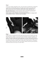
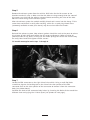
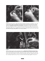
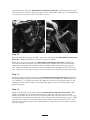
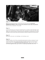
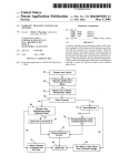
™
Engine Management System
604-001
INSTRUCTIONS
For 2005 - 2007
H arley-Davidson ® FL Models
2
Revolution Performance was founded with two major goals
in mind – to go that extra mile providing a superior level of customer
service and support in the V-Twin performance industry and to provide an
outlet for a complete line of performance components and services for
Harley-Davidson® Evo Big Twin® and Twin Cam® 88 as well as Buell®
American Motorcycles. Revolution Performance carries a full line of
aerospace aluminum alloy cylinders for Harley-Davidson® and Buell®
American motorcycles as well as a complete inventory of performance
components to make your package work together. The staff at Revolution
Performance brings a great deal of engine development experience to the
table not only in several disciplines of professional racing but in street
applications as well. From the individual who wants a one stop shop for
all his performance component needs to the shop owner seeking a
reliable supplier of parts and services we are here to help. We also have
a long history in professional race team support so we can not only
assist in your R&D efforts but with our manufacturing capabilities we can
make your ideas reality with the utmost in security. We use our expertise
to help OEMs produce better racing components as well as parts that
make it to the street. We work closely with premier engineers at
Harley-Davidson® on many of their projects and our customers receive
that same level of dedication. Our commitment to providing the best
components and customer service in the industry is a basis for
everything we do so that the customer can meet any realistic
performance goal that they set for themselves.
3
HD Tuner Installation Instructions for 20052007 FL Models
Revolution Performance LLC makes no claims to the suitability of this product for your
motorcycle. Use of this product may void the manufacturer’s warranty and may void
federal emissions compliance of your vehicle. This product is intended for closed course/
racing use only.
Use of leaded fuels will significantly shorten the life of O2 sensors, and may over
time cause poor vehicle performance. It is suggested that if leaded fuels are being
used that the O2 sensors be changed every 10 hours of vehicle operation to ensure
peak performance.
Installation of this performance kit requires a moderate level of vehicle mechanical
knowledge. If you feel that you may not be capable of the safe installation of this
product, please contact your local service provider for professional assistance.
Installation of this product on your motorcycle requires an exhaust system with O2
sensor bungs installed. You may either upgrade your exhaust system to a ’07 system that
would have the sensor bungs already installed in it, or weld O2 bungs into your system.
If welding is required it is critical that the welds be air tight. An air leak at the sensor
bung will cause the product to malfunction. If you are not comfortable in the ability to
get an air tight weld please have the sensors welded to your pipes by a qualified welder.
Details about sensor placement prior to welding can be found in step 4. Revolution
Performance can supply O2 sensor bungs for a nominal fee. Please contact Revolution
Performance if O2 bungs are needed.
Before beginning installation verify that all necessary components have arrived. The kit
should include:
1
Control Box
2
Wide Band O2 Sensors
2
Easy Turn Wire Connectors (2007 models only have 1 connector)
1
ECU Shipment Box
1
Customer Information Data Sheet
Step 1
Remove the seat, saddlebags, and side covers from your vehicle. Refer to your owner’s or
service manual for details.
Step 2
Remove the maxi-fuse and ECU from your vehicle. Refer to your owner’s or service
manual for details.
4
Step 3
Fill out the customer information sheet. This sheet needs to be filled out as completely
as possible. Your VIN number needs to be written on the sheet or the sheet will be
returned to you so that the VIN may be completed. Be sure to include your return
address and a phone number where you may be reached. When completed fold
your information sheet up and pack it into the mailer, preaddressed and posted to
Revolution Performance, with your ECU and send it in the mail. Your ECU will be
processed and in several days you will receive your ECU back.
If your exhaust system already has O2 sensor bungs installed in it simply install
the provided O2 sensors, and omit steps 4 through 6.
Step 4
If your vehicle is not equipped with O2 bungs they will need to be installed. The ideal
placement for the sensors is 6 to 8 inches from the exhaust port on each cylinder. The
bungs should be installed so that the O2 sensor inclination is between horizontal and
vertical. This allows water that naturally condenses in a cool exhaust system to drain
out of the sensor, and prevents sensor damage from occurring. The easiest way to locate
the sensor on the pipe is to partially thread the sensor into the bung and hold it up to
the exhaust to check for clearance. Once a good spot has been found use a permanent
marker to outline the bung and mark it for welding. Photos illustrating ideal placement
on both the front and rear pipes are shown above.
5
Step 5
Remove the exhaust system from the vehicle. Drill holes for the O2 sensors at the
locations marked in step 4. Make sure that the holes are large enough that the snout of
the sensor can stick into the exhaust stream without contacting the sides of the hole.
Weld the sensor bungs to the exhaust system.
After the exhaust system has cooled carefully thread each sensor into the bungs. If the
sensor does not thread in easily after welding, a M18 X 1.5 spark plug thread chase
(commonly available at auto parts stores) may be used to clean the threads.
Step 6
Reinstall the exhaust system. New exhaust gaskets should be used at the ports to reduce
the chance of leaks that could affect the O2 sensor performance. Make sure that all
potential leaks at slip joints in the pipes are sealed (orange O2 sensor safe silicone may
be used). Now install and tighten the O2 sensors.
’07 model motorcycles omit steps 7 through 9.
Step 7
Locate the ECU connector on the right side of the vehicle. Using a small flat blade
screwdriver depress the locking tab on the side of the clear portion of the ECU
connector. Pull on the clear portion of the connector to remove it from the connector
body (see photo above).
Separate the back of the connector body halves by inserting the blade of the screwdriver
between them and prying the 2 halves apart (see photos on next page).
6
7
Step 8
Remove the blue seal pins from the back of the ECU connectors at locations 8 & 23 by
prying them up with a screwdriver and using a pliers to pull them from their sockets.
Locate the Revolution Performance Precision™ Controller and insert the white wire
from the controller into hole 8, and the blue wire into hole 23. Make sure the pins are
fully seated. When this is accomplished reinstall the clear plastic cover over the end of
the ECU connector. (note: Make sure all pins are seated. If the clear cover will not slide
on and lock in place easily there is a pin out of place.)
Step 9
Locate a blue easy turn wire connector from the Revolution Performance Precision™
kit, and disassemble the connector. Using a razor knife, slice 4” of wire harness sheath
back at the ECU connector to expose some wire length. Locate the black wire with the
white stripe coming from pin 26 on the ECU connector. Place the U portion of the easy
turn connector around this wire, and screw the connector body together. Insert the
8
single black wire from the Revolution Performance Precision™ EMS through the cap of
the connector and twist it tight to make a secure connection. When this is accomplished
use zip ties to secure all wires and sheath in place.
B
A
Step 10
Reinstall your ECU. Connect the ECU connector, and secure the Revolution Performance
Precision™ EMS to the ECU as pictured in photo ”A“ above.
Route the red power wire from the Revolution Performance Precision™ EMS under
the seat and over to the left side of the motorcycle. Remove the fuse block from the
motorcycle and locate the headlight circuit (usually a blue wire). Using an easy turn
wire connector attach the power wire from the EMS to the headlight circuit. Using zip
ties, neatly secure the wires making sure to provide strain relief for the new power wire.
Step 11
Secure the ground ring terminal from the Revolution Performance Precision™ EMS to
the factory grounding lug in the backbone of the frame. On 2005 and 2006 models use
a ¼-20 bolt ½” in length and attach the ground wire to the pre-threaded hole in the
backbone of the frame. Scratch paint away from ground wire if necessary to ensure a
good connection.
Step 12
Route the front O2 sensor wires from the Revolution Performance Precision™ EMS
along the bottom of the frame rails and plug it into the front O2 sensor. On ’07
models also route the feed-back wire from the EMS with the O2 sensor wire and plug
the feedback wire into the factory O2 sensor plug on the vehicle wiring harness. Make
sure that these wires are secured tightly to the lower frame rail of the vehicle, and
that the wires route on top of any frame braces so that they cannot come in contact
with the ground.
9
Step 13
Route the wire from the rear O2 sensor back to the left side of the Revolution
Performance Precision™ EMS, and plug in the connector. On ’07 models route the rear
feedback wire through the frame and plug the connector into the stock wiring harness.
Secure all wires as pictured in the photo.
Step 14
Install the maxi-fuse, and switch the vehicle to the run position. Verify that both sensor
lights on the control box are flashing slowly. After 30 seconds the lights will either flash
rapidly or be solid on. Place a screw driver on the calibration screw and adjust it so that
the light has just turned from flashing rapidly to steady on. Repeat this for cylinder #2.
Step 15
Reassemble side covers and saddlebags, and install your seat.
Step 16
Start your vehicle. Let it idle up to operating temperature (at least 5 minutes). Try not
to blip the throttle unless necessary to keep the engine running. The vehicle may run
poorly initially until the Revolution Performance Precision™ EMS finds the correct
parameters for your engine. You will notice that after several minutes your vehicle will
run increasingly better. After your vehicle is at operating temperature shut it off.
10
Step 17
Gear up and go ride! Your vehicle is now equipped with the finest dynamic fuel
injection controls available. It will optimize as you ride, and grow with you as your
bike does. As equipped it will self compensate for minor changes in intake and exhaust
configurations, heads, and cams. The ECU functions like normal and your vehicle can be
serviced by any dealer.
Want to perform significant modifications to your motor? No problem—simply download
a new customer information form from the Revolution Performance web site (www.
revperf.com) and send your ECU and form to us. For a small fee we will update your ECU
for the new engine, and you are good to go. Your bike will tune itself!
NO Dealer
NO DYNO
NO PROBLEM
11
Revolution Performance
1312 Pilgrim Road
Plymouth, WI 53073
Toll Free 1-866-892-2109
Phone 920-892-2109 Fax
920-893-4830
[email protected]
www.revperf.com
© 2010 Millennium Technologies. All rights reserved.
Harley-Davidson®, Buell®, Twin Cam®, Evolution® and Big Twin® are registered
trademarks of Harley-Davidson, Inc.
RP0008 vA (8/9/2010)