1
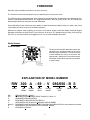
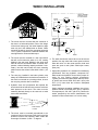
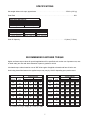
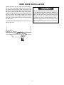
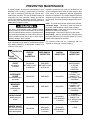
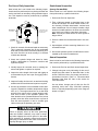
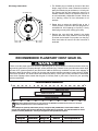
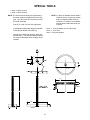
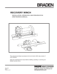
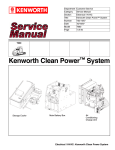
BRADEN
RW300A
INSTALLATION, MAINTENANCE AND SERVICE MANUAL
PACR WINCH DIVISION
LIT2231 R1
5/2005
Printed in U.S.A.
Copyright 2005 PACCAR Winch Division.
All rights reserved.
P.O. BOX 547 BROKEN ARROW, OK U.S.A. 74013
PHONE (918) 251-8511 FAX (918) 259-1575
www.paccarwinch.com
TABLE OF CONTENTS
FOREWORD . . . . . . . . . . . . . . . . . . . . . . . . . . . . . . . . . . . . . . . . . . . . . . . . . . . .2
GENERAL SAFETY RECOMMENDATIONS . . . . . . . . . . . . . . . . . . . . . . . . . . .3
THEORY OF OPERATION . . . . . . . . . . . . . . . . . . . . . . . . . . . . . . . . . . . . . . . . .4
WINCH INSTALLATION . . . . . . . . . . . . . . . . . . . . . . . . . . . . . . . . . . . . . . . . . . .6
SPECIFICATIONS . . . . . . . . . . . . . . . . . . . . . . . . . . . . . . . . . . . . . . . . . . . . . . .7
RECOMMENDED FASTENER TORQUE . . . . . . . . . . . . . . . . . . . . . . . . . . . . .7
WIRE ROPE INSTALLATION . . . . . . . . . . . . . . . . . . . . . . . . . . . . . . . . . . . . . . .8
PREVENTIVE MAINTENANCE . . . . . . . . . . . . . . . . . . . . . . . . . . . . . . . . . . . . .9
RECOMMENDED PLANETARY HOIST GEAR OIL . . . . . . . . . . . . . . . . . . . . .11
SPECIAL TOOLS . . . . . . . . . . . . . . . . . . . . . . . . . . . . . . . . . . . . . . . . . . . . . . .12
TROUBLESHOOTING . . . . . . . . . . . . . . . . . . . . . . . . . . . . . . . . . . . . . . . . . . .13
DISASSEMBLY OF WINCH . . . . . . . . . . . . . . . . . . . . . . . . . . . . . . . . . . . . . . .16
BRAKE CYLINDER SERVICE . . . . . . . . . . . . . . . . . . . . . . . . . . . . . . . . . . . . .18
BRAKE CLUTCH ASSEMBLY SERVICE . . . . . . . . . . . . . . . . . . . . . . . . . . . . .21
PLANET CARRIER SERVICE . . . . . . . . . . . . . . . . . . . . . . . . . . . . . . . . . . . . .22
WINCH ASSEMBLY . . . . . . . . . . . . . . . . . . . . . . . . . . . . . . . . . . . . . . . . . . . . .24
CROSS-SECTION DRAWING AND PARTS KEY . . . . . . . . . . . . . . . . . . . . . .26
METRIC CONVERSION TABLE . . . . . . . . . . . . . . . . . . . . . . . . . . . . . . . . . . . .30
1
FOREWORD
Read this entire publication and retain it for future reference.
The minimum service intervals specified are for operating hours of the prime mover.
The following service instructions have been prepared to provide assembly, disassembly and maintenance information for the Braden Model RW300A. It is suggested that before doing any work on this unit, all assembly and
disassembly instructions should be read and understood.
Some illustrations in this manual may show details or attachments that are different from your winch. Also, some
components have been removed for illustrative purposes.
Whenever a question arises regarding your winch or this manual, please contact the Braden Technical Support
Department via phone at (918)-251-8511, from 08:00 to 16:30 hours, CT, Monday through Friday, via fax at (918)259-1575, or via email at [email protected], for the latest available information.
Model Number
Serial Number
OIL LEVEL
SIGHT GLASS
The winch serial number and model number are
stamped into a data plate located on the drum
bearing support end bracket. The serial number
is steel stamped into the top of the motor end
support plate. Always refer to the serial number
and model number when requesting information
or service parts.
VENT
LOWERING PORT
SAE -12 ORB
(1 1/16-12 THRD)
EXPLANATION OF MODEL NUMBER
RW 300 A - 69 - V 086/050 - B S
WINCH
RW
300
A
69
V
086/050
B
S
MAX
RATING
DESIGN
MODEL
GEAR
RATIO
PISTON
MOTOR
MOTOR
SIZE
BRAKE OPTION
REDUCER DRIVE / WINCH
DESIGNATES APPROXIMATE PEAK TORQUE X 1000 lb.-in.
DESIGNATES DESIGN SERIES
DESIGNATES GEAR REDUCTION RATIO :1
DESIGNATES PISTON MOTOR VARIABLE DISPLACEMENT
DESIGNATES MOTOR DISPLACEMENT IN CUBIC INCH/REVOLUTION; LOW RANGE/HIGH RANGE
DESIGNATES UNIT EQUIPPED WITH INTERNAL BRAKE
DESIGNATES SPECIAL
2
GENERAL SAFETY RECOMMENDATIONS
Safety and informational callouts used in this manual include:
CAUTION
WARNING – This emblem is used to warn against
hazards and unsafe practice which COULD result in
severe personal injury or death if proper procedures
are not followed.
CAUTION – This emblem is used to warn against
potential or unsafe practices which COULD result in
personal injury and product or property damage if
proper procedures are not followed.
Safety for operators and ground personnel is of prime concern. Always take the necessary precautions to ensure
safety to others as well as yourself. To ensure safety, the prime mover and winch must be operated with care and
concern by the operator for the equipment and a thorough knowledge of the machine’s performance capabilities.
The following recommendations are offered as a general safety guide. Local rules and regulations will also apply.
14. Keep hydraulic system clean and free from contamination at all times.
1. Be certain equipment (boom, mast, sheave blocks,
pendants, etc.) is either lowered to the ground or
blocked securely before servicing, adjusting, or
repairing winch.
15. Use correct anchor method for wire rope and pocket in drum. Do not use knots to secure or attach
wire rope. For additional safety, ALWAYS maintain
a minimum of five (5) wraps of wire rope on the
drum.
2. Be sure personnel are clear of work area BEFORE
operating winch.
3. Read all warning and caution tag information provided for safe operation and service of winch.
16. Never attempt to clean, oil or perform any maintenance on a machine with the engine or prime mover
running, unless instructed to do so in this manual.
4. Inspect rigging and winch at the beginning of each
work shift. Defects should be corrected immediately.
17. Never operate winch controls unless you are properly positioned at the operators station and you are
sure personnel are clear of the work area.
5. Keep equipment in good operating condition.
Perform scheduled servicing and adjustments listed
in the “Preventive Maintenance” section of this manual.
18. Assure that personnel who are responsible for hand
signals are clearly visible and that the signals to be
used are thoroughly understood by everyone.
6. An equipment warm-up procedure is recommended
for all start-ups and essential at ambient temperatures below +40°F (4°C). Refer to “Warm-up
Procedure” listed in the “Preventive Maintenance”
section of this manual.
19. Ground personnel should stay in view of the operator and clear of winch drum. Do not allow ground
personnel near winch line under tension.
20. Do not exceed the maximum pressure, PSI (kPa), or
flow, GPM (LPM), stated in the winch specifications.
7. Operate winch line speeds to match job conditions.
8. Leather gloves should be used when handling wire
rope.
21. Install guarding to prevent personnel from getting
any part of body or clothing caught at a point where
the cable is wrapped onto the drum or drawn
through guide rollers.
9. Never attempt to handle wire rope when the hook
end is not free. Keep all parts of body and clothing
clear of cable rollers, cable entry area of fairleads,
sheaves and winch drum.
22. “Deadman” controls, which automatically shut off
power to the winch whenever the operator leaves
his station, should be installed whenever practicable.
10. When winding wire rope on the winch drum, never
attempt to maintain tension by allowing wire rope to
slip through hands. Always use “Hand-Over-Hand”
technique.
23. Never allow anyone to stand under a suspended
load.
11. Never use wire rope with broken strands. Replace
wire rope.
24. Avoid sudden “shock” loads or attempting to “jerk”
load free. This type of operation may cause heavy
loads, in excess of rated capacity, which may result
in failure of cable and winch.
12. Do not weld on any part of the winch.
13. Use recommended hydraulic oil and gear lubricant.
3
THEORY OF OPERATION
DESCRIPTION OF WINCH
The static brake system has three operating components:
1. Spring Applied, Multiple Friction Disc Static Brake
2. Brake Clutch Assembly
3. Hydraulic Piston and Cylinder
The winch has four basic component parts:
1. Winch base
2. Hydraulic motor and brake valve
3. Brake cylinder and motor support
4. Drum assembly
The drum assembly consists of four basic assemblies:
1. Drum with integral ring gear
2. Output planetary gear set
3. Secondary planetary gear set
4. Primary planetary gear set
The hydraulic motor is bolted to the brake cylinder and
the base. The motor end of the drum, running on dual
tapered bearings, is supported by the brake cylinder.
The other end of the drum runs on a spherical bearing
on the support bolted to the base. The ring gear for the
planetary sets is machined into the drum’s inside surface.
Figure 2
Motor
Static
Brake
To
Tank
Brake
Valve
Pump
Control
Valve
WINCH OPERATION
The hydraulic motor drives the sun gear of the primary
planetary gear set through the splined inner race of the
brake clutch. When driven by the sun gear, the primary
planet gears walk around the ring gear in the drum and
drive the primary planet carrier.
Low Pressure Medium Pressure High Pressure
Figure 3
Motor
Static
Brake
The primary planet carrier drives the secondary sun
gear. The secondary planet gears drive the secondary
planet carrier, which drives the output sun gear. The
output planet carrier is splined to the brake cylinder and
cannot rotate. Therefore, as the output planet gears are
driven by the sun gear, they will drive the ring
gear/drum.
To
Tank
Brake
Valve
Pump
DUAL BRAKE SYSTEM – DESCRIPTION
Control
Valve
The dual brake system consists of a dynamic brake system and a static brake system.
The dynamic brake system has two operating components:
1. Brake valve assembly
2. Hydraulic motor
The brake valve is basically a counterbalance valve. It
contains a check valve to allow free flow of oil to the
motor in the hoisting direction and a pilot operated,
spring-loaded spool valve that blocks the flow of oil out
of the motor when the control valve is placed in neutral.
When the control valve is placed in the lowering position, the spool valve remains closed until sufficient pilot
pressure is applied to the end of the spool to shift it
against spring pressure and open a passage. After the
spool valve cracks open, the pilot pressure becomes
flow-dependent and modulates the spool valve opening
which controls the lowering speed.
Low Pressure Medium Pressure High Pressure
Figure 4
Motor
Static
Brake
Brake
Valve
To
Tank
Pump
Control
Valve
Figures 2, 3 & 4 show a simplified version of the brake
valve for illustrative purposes.
Low Pressure Medium Pressure High Pressure
4
The static brake is released by the brake valve pilot
pressure at a pressure lower than that required to open
the pilot operated spool valve. This sequence assures
that dynamic braking takes place in the brake valve and
that little, if any, heat is absorbed by the friction brake.
Static Friction Brake Applied
Figure 5
Sprag
Cams
The friction brake is a load holding brake only and has
nothing to do with dynamic braking or rate of descent of
a load.
Hoisting
The brake clutch is splined to the primary sun gear shaft
between the motor and the primary sun gear. It will
allow this shaft to turn freely in the direction to raise a
load and lock up to force the brake discs to turn with the
shaft in the direction to lower a load. Figures 5 and 6.
The hydraulic cylinder, when pressurized, will release
the spring pressure on the brake discs, allowing the
brake discs to turn freely.
Permits free
shaft rotation
while hoisting
DUAL BRAKE SYSTEM – OPERATION
When hoisting a load, the brake clutch which connects
the motor shaft to the primary sun gear, allows free rotation. The sprag cams lay over and permit the inner race
to turn free of the outer race. Figure 5. The friction brake
remains fully engaged. The winch, in raising a load, is
not affected by any braking action. Figure 2.
Figure 6
Static Friction Brake Applied
Sprag
Cams
When the lifting operation is stopped, the load attempts
to turn the primary sun gear in the opposite direction.
This reversed input causes the sprag cams to instantly
roll upward and firmly lock the shaft to the fully engaged
friction brake. Figure 6.
Stopped,
Holding
Load
When the winch is powered in reverse, to lower the
load, the motor cannot rotate until sufficient pilot pressure is present to open the brake valve. Figures 3 & 4.
The friction brake within the winch will completely
release at a pressure lower than that required to open
the brake valve. The extent to which the brake valve
opens will determine the amount of oil that can flow
through it and the speed at which the load will be lowered. Increasing the flow of oil to the winch motor will
cause the pressure to rise and the opening in the brake
valve to enlarge, speeding up the descent of the load.
Decreasing this flow causes the pressure to lower and
the opening in the brake valve to decrease thus slowing
the descent of the load.
Load attempts to rotate shaft in opposite direction.
Brake clutch locks sun gear shaft to friction brake.
When the control valve is shifted to neutral, the pressure will drop and the brake valve will close, stopping
the load. The friction brake will engage and hold the
load after the brake valve has closed.
The friction brake receives very little wear in the lowering operation. All of the heat generated by the lowering
and stopping of a load is absorbed by the hydraulic oil
where it can be readily dissipated.
5
WINCH INSTALLATION
WINCH ASSEMBLY
W/BRAKE VALVE
& STATIC BRAKE
BRAKE
VALVE
WINCH BRAKE
19°
BR
19°
CASE
DRAIN
CONTROL
VALVE
1. The winch must be mounted with the centerline of
the drum in a horizontal position. Due to the design
of the winch base group, the cable departure angle
must only be in the shaded area as shown. When
mounting the winch, use all four mounting holes with
1.25 in. grade 8 capscrews, hardened washers and
nuts tightened to recommended torque.
2. The winch must be mounted to a flat, rigid surface
that will not flex when the winch is in use, causing
binding in the gear train. Binding in the winch gear
train will result in accelerated wear of internal components, reduced hoisting capacity and heat. If necessary, use shim stock under the winch mounting
pads to ensure the surface is flat within 0.020 in. (0.5
mm).
3. The vent plug, installed in the brake cylinder, must
always be located above the horizontal centerline. If
the winch is mounted on a pivoting surface, be sure
the vent plug remains above centerline.
4. Hydraulic lines and components that operate the
winch should be of sufficient size to assure minimum
back pressure at the winch. The motor must be
externally drained directly to the reservoir to avoid
motor shaft seal failure.
a
b
First sheave
or load
5. The winch must be mounted perpendicular to an
imaginary line from the center of the winch to the first
sheave to ensure even spooling. Make certain the
fleet angle is between ½ and 1 ½ degrees.
6
PUMP
6. The winch directional control valve must be a three
position, four way valve with a motor spool such that
when the valve is in the center position, both work
ports are open to tank (often called open center,
open port).
7. High quality hydraulic oil is essential for satisfactory
performance and long hydraulic component life.
Make certain the hydraulic oil used is the proper viscosity for your starting ambient temperature.
Typically, the maximum cold weather start-up viscosity should not exceed 5000 SUS with a pour point
20°F (11°C) lower than the minimum anticipated
temperature.
Under continuous operating conditions, the oil temperature should not exceed 180°F (82°C). Optimum
oil temperature is 120-140°F (49-60°C). Unless otherwise specified by the vehicle manufacturer, the
hydraulic oil filter should have a 10 micron rating.
SPECIFICATIONS
Unit weight without wire rope, approximate . . . . . . . . . . . . . . . . . . . . . . . . . . . . . . . . . . . .1370 lb. (621 kg)
Gear Ratio . . . . . . . . . . . . . . . . . . . . . . . . . . . . . . . . . . . . . . . . . . . . . . . . . . . . . . . . . . . . . . . . . . . . . . .69:1
Cable Drum Dimensions:
Barrel Diameter
Flange Diameter
Barrel Length
15.25 in. (387 mm)
20.0 in. (508 mm)
13.5 in. (343 mm)
Cable Storage Capacity
Layer
7/8 in. (22 mm)
1
65 ft. (19.8 m)
2
137 ft. (41.8 m)
Gear Oil Capacity . . . . . . . . . . . . . . . . . . . . . . . . . . . . . . . . . . . . . . . . . . . . . . . . . . . . . . .15 pints (7.1 liters)
RECOMMENDED FASTENER TORQUE
Higher and lower torque values for special applications will be specified; such as the use of spanner nuts, nuts
on shaft ends, jam nuts and where distortion of parts or gaskets is critical.
Lubricated torque values based on use of SAE 30wt engine oil applied to threads and face of bolt or nut.
Avoid using thread lubricants as the applied torque may vary by 10-40% depending upon product used.
Q
Torque (LB-FT)
Bolt Dia. Thds Per
Grade 5
Grade 8
Dry Lubed Dry Lubed
Inches
Inch
10
265
200
3/4
380
280
16
9
7/8
420
325
600
450
14
8
485
910
640
1
680
14
7
790
590
1290
970
1 1/8
12
7
1 1/4
1120
835
1820 1360
12
6
1460 1095 2385 1790
1 3/8
12
6
1940 1460 3160 2370
1 1/2
12
Torque (LB-FT)
Grade 5
Grade 8
Dry Lubed Dry Lubed
Bolt Dia. Thds Per
Inches
Inch
20
8
6
12
9
1/4
28
18
17
13
24
18
5/16
24
16
31
23
45
35
3/8
24
14
50
35
70
50
7/16
20
13
75
55
110
80
1/2
20
12
110
80
150
110
9/16
18
11
150
115
210
160
5/8
18
To convert lb. ft. to kg-m, multiply lb. ft. value by 0.1383.
7
WIRE ROPE INSTALLATION
Prepare the end of the wire rope as recommended by
the wire rope manufacturer. Insert the free end of the
wire rope through the opening in the drum flange. Push
the wire rope into the anchor pocket until the end of the
wire rope is even with the outer edge of the pocket.
Install the clamp plate onto the drum flange with the thin
end of the clamp wedge toward the dead end of the wire
rope. Apply a light load of approximately 500 lb. (227
kg) to the wire rope as the new wire rope is wound onto
the cable drum.
The clamp plate wire rope anchor system is not capable of supporting the rated load. Always MAINTAIN a
minimum of five wraps of wire rope on the cable
drum. If the wire rope is fully reeled out, the wire rope
may slip out of the drum causing a loss of load control which may result in property damage, injury or
death. We suggest that the last 5-6 wraps of wire
rope be painted bright red to serve as a visual warning.
The anchor system is designed for use only with 7/8 in.
(22mm) wire rope.
8
PREVENTIVE MAINTENANCE
A regular program of preventive maintenance for your
planetary hoist is strongly recommended to minimize
the need for emergency servicing and promote safe,
reliable hoist operation. The user of Braden products is
responsible for hoist inspection, testing and maintenance with frequency dependent upon the severity of
the hoist duty cycle and thoroughness of the preventive
maintenance program in effect.
Inspection procedures for hoists are divided into five
general categories based upon the hoist usage or duty
cycle, which in turn determines different, appropriate
intervals for inspections. The usage categories must be
assigned by the hoist user/owner on a consistent unitby-unit basis. The five hoist usage categories are as follows:
Idled: - The hoist has not been used for three months.
Infrequent Usage - The hoist is used less than ten
hours per month based on a three month average.
Moderate Usage - Hoist used 10-50 hours per month
based on a three month average.
Heavy Usage - Hoist used 50-200 hours per month.
Severe Duty - Hoist is operated more than 200 hours
per month OR where 50% of the lifts exceed 75% of the
Braden rated capacity for the hoist.
Any time a hoist exhibits erratic operation and/or
unusual noise, the hoist must be taken out of service
until it is inspected and serviced by a qualified technician. Continued operation of a hoist with a defect in a
critical component may lead to loss of load control,
property damage, injury or death.
A record of written, dated and signed inspections, load
tests, maintenance and repairs or modifications must be
kept readily available in an appropriate location for a
minimum of five years.
INSPECTION
USAGE
CATEGORY
IDLED
Not used for
3 months
INFREQUENT
USAGE
The following chart lists the inspections that are
required for each type of usage category.
PRE-USE
DAILY
INSPECTION
SEMI-ANNUAL
INSPECTION
REQUIRED
BEFORE PLACED
IN SERVICE
REQUIRED
BEFORE PLACED
IN SERVICE
REQUIRED
REQUIRED
ANNUAL
INSPECTION
TEAR-DOWN
INSPECTION
--
REQUIRED IF
MAINTENANCE
& REPAIR
HISTORY
UNKNOWN
REQUIRED
5 YEARS
3 YEARS IF NOT
SUBJECT TO
FULL INSPECTION
PROGRAM
REQUIRED
4 YEARS
2 YEARS IF NOT
SUBJECT TO
FULL INSPECTION
PROGRAM
less than ten hours
per month
MODERATE
USAGE
REQUIRED
REQUIRED
10-50 hours per
month
HEAVY USAGE
50-200 hours per
month
REQUIRED
SEVERE USAGE
200+ hours per month
or 50% of lifts exceed
75% rated capacity
REQUIRED
REQUIRED
REQUIRED
QUARTERLY
(3 months)
9
REQUIRED
SEMI-ANNUALLY
(6 months)
REQUIRED
SEMI-ANNUALLY
(6 months)
3 YEARS
1.5 YEARS IF NOT
SUBJECT TO
FULL INSPECTION
PROGRAM
1 YEAR
Pre-Use or Daily Inspection:
Semi-Annual Inspection
(every six months):
Must include but is not limited to the following inspections that will be performed prior to placing the hoist into
service and then as necessary during extended operation. This inspection must be performed by a qualified
technician.
Must include but is not limited to the following inspections performed by a qualified technician.
1. Perform the Pre-Use inspection.
2. Take a lubricant sample as described later in this
section and analyze it for wear metals content, correct viscosity, lubricant deterioration, moisture and
other contaminants. If the oil sample contains a high
amount of metallic particles, the hoist must be taken
out of service to undergo a tear-down inspection.
Note: Oil analysis cannot detect nor warn against a
fatigue failure.
HOIST
OIL FILL & DRAIN
SAE -8 ORB
(3/4-16 THRD)
OIL FILL
OIL FILL/DRAIN
ACCESS
ACCESS
HOLE
HOLE
CABLE POCKET AND
ANCHOR TO ACCEPT
7/8 WIRE ROPE
3. Perform a brake test as described later in this section.
MODEL NO.
SERIAL NO.
4. Inspect/tighten all hoist mounting fasteners to recommended torque.
1. Check for external oil leaks and repair as necessary.
This is extremely important due to the accelerated
wear that will result from insufficient lubricating oil in
the hoist. Check the oil level monthly if no external
oil leaks are detected.
5. Service the hydraulic system oil and filters as recommended by the vehicle manufacturer.
Annual Inspection:
2. Check the hydraulic fittings and hoses for leaks,
chaffing, deterioration or excessive corrosion and
repair as required.
Must include but not limited to the following inspections
that must be performed by a qualified technician.
1. Perform the Pre-Use and Semi-Annual inspections.
3. Visually inspect for corroded, loose or missing fasteners and tighten or replace as required.
2. Change hoist gear cavity lubricating oil after an oil
sample has been taken as described later in this
section. Refill the hoist to the proper level with recommended lubricant. Refer to "Recommended
Planetary Hoist Gear Oil" later in this section for
more information.
4. Inspect the entire length of wire rope and rigging as
recommended by the wire rope and rigging manufacturer.
5. Inspect all safety devices such as anti-two-blocking
switches and limit switches and repair as required.
On new hoists, change gear oil after the first 50
operating hours then every 500-1000 operating
hours or annually depending upon hoist usage as
shown on Page 9.
6. A warm-up procedure is recommended at each startup and is essential at ambient temperatures below
40°F (4°C). The engine should be run at low RPM
with the hoist control valve in neutral allowing sufficient time to warm up the hydraulic system. The
hoist should then be operated without a load, at low
speeds, raise then lower several times to prime all
lines with warm hydraulic oil and to circulate gear
lubricant through the planetary gear train.
Failure to properly warm up the hoist, particularly
under low ambient conditions, may result in temporary brake slippage due to thick gear oil in the brake
clutch assembly or hydraulic system back-pressure
attempting to release the brake, which could result in
property damage, injury or death.
10
Oil change instructions:
1. The fill/drain plug is located on the end of the drum
flange, away from the motor. Rotate drum barrel to
place the fill/drain plug at the bottom, 6 o'clock position. Remove the plug and capture the gear oil in a
suitable container. Recycle or dispose of used oil in
an environmentally responsible manner. While the
oil is draining, collect oil from mid-stream for oil
analysis.
Oil Fill/Drain Plug
2. Rotate drum to place the drain/fill plug at the 3
o'clock position. Fill winch to the level plug with recommended oil. Oil fill capacity is 15 pints (7.1 liters).
Install plug securely after refilling gear cavity.
3. Remove the vent relief plug located in the brake
cylinder above the motor. Clean the vent relief plug
in solvent and reinstall. Do not paint over the plug.
Drum seal leaks will result if the relief vent hole is
restricted.
RECOMMENDED PLANETARY HOIST GEAR OIL
Failure to use the proper type and viscosity of planetary gear oil may contribute to intermittent brake clutch slippage which could result in property damage, severe personal injury or death. Some gear lubricants contain large
amounts of EP (extreme pressure) and anti-friction additives which may contribute to brake clutch slippage or
damage to brake friction discs or seals. Oil viscosity with regard to ambient temperature is also critical to reliable
brake clutch operation. Our tests indicate that excessively heavy or thick gear oil may contribute to intermittent
brake clutch slippage. Make certain that the gear oil viscosity used in your hoist is correct for your prevailing
ambient temperature.
PREVAILING AMBIENT TEMPERATURE
oF
-40
-30
-20
-10
0
10
20
30
40
50
60
70
80
90
100
110
130 oF
120
EXXON SPARTAN EP220 OR EQUIVALENT
AGMA 5 EP, ISO VG 220
EXXON SPARTAN EP150 OR EQUIVALENT
AGMA 4 EP, ISO VG 150
MOBILGEAR SHC 150 or 220
SYNTHETIC OR EQUIVALENT
oC
-40
i
-30
-20
-10
0
10
20
30
40
50
oC
NOTE: SHADED TEMPERATURE RANGE IN THE CHART ABOVE NOT RECOMMENDED FOR SEVERE APPLICATIONS SUCH AS: OFFSHORE
CRANES, SUSTAINED FAST DUTY CYCLES OR FREQUENT LIFTING.
Texaco Meropa 150, previously used as factory fill, may no longer be widely available due to current market conditions. As of
mid-year 2002, planetary hoists are factory filled with Exxon Spartan EP150, or equivalent. The chart below relates the Texaco
products to 4 currently available oils. Consult your oil supplier for other equivalent oils if required.
Texaco
Exxon
Mobil
Shell
Chevron
Meropa 150
Spartan EP 150
Mobilgear 629
Omala 150
Gear Compounds EP 150
Meropa 220
Spartan EP 220
Mobilgear 630
Omala 220
Gear Compounds EP 220
9/2002
11
SPECIAL TOOLS
2 each ½-13NC eye bolt
2 each ¾-10NC eye bolt:
NOTE: The first two items below are required only if
the motor support is separated from the ring
gear. The other tools are required to service
the brake assembly.
NOTE: If a press is available (with at least 5
inches of travel), only part (A) shown
below is required (center hole not
required). If a press is not available,
all parts shown and listed below are
required.
3 each 7/8 - 9NC x 6 inch long capscrews
A ratcheting internal snap ring pliers capable
of handling an N5000 700 snap ring.
1 each 1 - 8 NC threaded rod, 14 inches long
1 each 1 - 8 NC nuts
1 each 1 inch plain washer
All units use a single coil spring to apply the
internal brake. The following spring compressor must be fabricated and is strongly recommended.
6.00
2.00
5.37
0.50
1.06
2.00
A
1.06
0.38
0.75
9.50
1.00
2.00
WELD
14.00
8.50
10.00
4.00
0.75
WELD
12
TROUBLESHOOTING
If a hoist ever exhibits any sign of erratic operation, or load control difficulties (load creeping down or chattering) appropriate troubleshooting tests and repairs must be performed immediately. Continued operation of a
hoist with a defect may result in property damage, injury or death.
TROUBLE
PROBABLE CAUSE
REMEDY
1. The problem could be a plugged internal
orifice or leaking cartridge body seal ring
on the counter-balance valve. If a small
piece of contamination entered the counter-balance (CB) valve cartridge, it may be
restricting the hydraulic signal to open the
valve. The pressure may be going too high
or the smooth action of the CB valve may
be impaired.
Remove the counter-balance cartridge from
the valve body and inspect condition of body
seal rings. Disassemble valve body and flush
with clean solvent to remove contamination.
Assemble valve using new seal rings on CB
valve cartridge. Install an accurate 0-1000
PSI (0-6900 kPa) test gauge in the brake
release hose. With no load on the hoist, slowly move the control lever into the lowering
position and record the pressure when the
drum begins to turn in the lowering direction.
The static brake will release at approximately 300 PSI (2070 kPa) and the CB valve
should open at approximately 1050 PSI
(7240 kPa).
A
The hoist will not lower the
load or not lower the load
smoothly.
If the cartridge body seals are leaking, the
pilot signal pressure may be lost or the oil
flow that the CB valve is modulating is
able to return to tank without the proper
control allowing the load to lower too early
or too quickly.
2. The friction brake may not be releasing as
a result of a defective brake cylinder seal.
NOTE: If the brake cylinder seal is defective you will usually find oil leaking from the
winch vent plug.
Check brake cylinder seal as follows:
A. Disconnect the swivel tee from the brake
release port. Connect a hand pump with
accurate 0-2000 psi gauge and shut-off valve
to the –4 J.I.C. fitting in the brake release port.
B. Apply 1000 psi to the brake. Close shut-off
valve and let stand for five (5) minutes.
C. If there is any loss of pressure in five (5)
minutes, the brake cylinder should be disassembled for inspection of the sealing surfaces
and replacement of the seals. Refer to “Motor
Support-Brake Cylinder Service”.
3. Friction brake will not release as a result of
damaged brake discs.
Disassemble brake to inspect brake discs.
Check stack-up height as described in “Motor
Support-Brake Cylinder Service”.
1. Same as A2.
Same as A2.
2. Motor seal may be defective as a result
of high back pressure or contaminated
oil.
Motor case drain back pressure must not
exceed 40 psi (275 kPa). Inspect hydraulic
system for a restriction in the return line to
the reservoir. Be sure plumbing is properly
sized to winch motor.
B
Oil leaks from vent plug.
Oil analysis may indicate contamination has
worn motor shaft and seal. Thoroughly flush
entire hydraulic system and install new filters
and oil. Install new motor seal.
13
TROUBLE
PROBABLE CAUSE
REMEDY
1. Excessive system back pressure acting on
the brake release port.
System back-pressure must not exceed 100
psi (690 kPa). Inspect hydraulic system for
restriction in the circuit from the motor to the
reservoir.
2. Friction brake will not hold due to worn or
damaged brake discs.
Same as Remedy 3 of Trouble A3.
3. Brake clutch is slipping.
Improper planetary gear oil may cause the
brake clutch to slip. Drain old gear oil and
flush winch with solvent. Thoroughly drain
solvent and refill winch with recommended
planetary gear oil listed in “Preventive
Maintenance”.
C
The brake will not hold a
load with the control lever
in neutral.
Brake clutch may be damaged or worn.
Disassemble and inspect brake clutch as
described in “Brake Clutch Service”.
D
The winch will not hoist the
rated load.
1. The winch may be mounted on an uneven
or flexible surface which causes distortion
of the winch base and binding of the gear
train. Binding in the gear train will absorb
horsepower needed to hoist the rated load
and cause heat.
Reinforce mounting surface.
2. System relief valve may be set too low.
Relief valve needs adjustment or repair.
Check relief pressure as follows:
If necessary, use shim stock to level winch.
Refer to “Winch Installation”.
First loosen, then evenly retighten all winch
mounting bolts to recommended torque.
A. Install an accurate gauge into the inlet
port of the brake valve.
B. Apply a stall pull load on the winch while
monitoring pressure.
C. Compare gauge reading to winch specifications. Adjust relief valve as required.
NOTE: If pressure does not increase in proportion to adjustment, relief valve may be
contaminated or worn out. In either case, the
relief valve may require disassembly or
replacement.
3. Be certain hydraulic system temperature
is not more than 180°F (82°C). Excessive
hydraulic oil temperatures increase motor
and pump internal leakage and reduce
performance.
Same as remedies for Trouble D1 & D2.
4. Winch line pull rating is based on 1st layer
of wire rope.
Refer to winch performance charts for additional information.
5. Rigging and sheaves not operating efficiently.
Perform rigging service as recommended by
rig manufacturer.
14
Same as remedies for Trouble E2.
PROBABLE CAUSE
TROUBLE
REMEDY
E
The winch runs hot.
1. Same as D1.
Same as remedies for Trouble D1.
2. Be certain that the hydraulic system temperature is not more than 180°F (82°C).
Excessive hydraulic oil temperatures may
be caused by:
A. Plugged heat exchanger.
Thoroughly clean exterior and flush interior.
B. Too low or too high oil level in hydraulic
reservoir.
Fill/drain to proper level.
C. Same as D2.
Same as remedies for Trouble D2.
D. Hydraulic pump not operating efficiently.
Engine low on horsepower or R.P.M.
Tune/adjust prime mover.
Check suction line for damage.
Pump worn. Replace pump.
3. Excessively worn or damaged internal
winch parts.
Disassemble winch to inspect/replace worn
parts.
1. Same as D2.
Same as remedies for Trouble D2.
2. Hydraulic oil flow to motor may be too low.
Same as remedies for Trouble E2.
3. Controls being operated too quickly.
Conduct operator training as required.
1. The winch may be mounted too close to
the main sheave, causing the fleet angle
to be more than 1-1/2 degrees.
Check mounting distance and fleet angle.
Reposition winch as required.
2. The winch may not be mounted perpendicular to an imaginary line between the
center of the cable drum and the first
sheave.
Refer to “Winch Installation”.
3. Could possibly be using the wrong lay
rope. There is a distinct advantage in
applying rope of the proper direction of lay.
When the load is slacked off, the several
coils on the drum will stay closer together
and maintain an even layer. If rope of
improper lay is used, the coils will spread
apart each time the load is removed.
Then, when winding is resumed, the rope
has a tendency to criss-cross and overlap
on the drum. The result is apt to be a flattened and crushed rope.
Consult wire rope manufacturer for recommendation of wire rope that best suits your
application.
4. The winch may have been overloaded,
causing permanent set in the wire rope.
Replace wire rope and conduct operator/rigger training as required.
F
Winch “chatters”
raising rated load.
while
G
The wire rope does not
spool smoothly on the
drum.
15
DISASSEMBLY OF WINCH
See cross-section illustration on page 26 and parts key
for reference.
6. Remove the brake release hose adapter from the
brake release port to prevent damage. Remove the
motor pilot adapter (40) from the brake cylinder.
1. Remove the wire rope from the cable drum and
rotate the drum until the fill/drain plug is at the bottom, six o'clock position. Remove the drain plug and
capture the gear oil in a suitable container. Recycle
or dispose of used oil in an environmentally responsible manner. Install the drain plug.
7. With a suitable hoist, turn the hoist over with the
motor end down. Remove the capscrews and lockwashers (99,100) that retain the tie-plates (101) to
the end-brackets (96, 97). Remove the drum bearing support and end-bracket assembly from the
cable drum.
2. Label the hydraulic hoses as they are removed from
the hoist motor. Install plugs in the open hoses and
motor ports to reduce entrainment of dirt in the open
port.
8. Remove the 16 socket head capscrews and lockwashers (12, 13) from the drum flange end (5). With
a plastic face mallet, unseat the drum flange end (5)
from the drum ring gear (60). Remove the drum
flange end from the drum ring gear.
CAUTION
The RW300 hoist weighs approximately 1370 lbs.
(621 kg). Use adequate lifting equipment.
3. Remove the hoist mounting fasteners and lift the
hoist from the mount. Begin disassembly by placing
the hoist on a stable work surface with the motor
end facing up. Secure the hoist in this position to
prevent it from falling and causing injury.
4. Remove the hose that connects the brake valve to
the brake release port. Remove the fasteners securing the motor to the brake cylinder assembly. Lift the
motor straight up to disengage the motor shaft from
the brake clutch assembly.
9. Remove the primary sun gear (2) from the primary
planet carrier assembly (71).
5. Remove the brake clutch assembly/brake hub (42)
from the brake cylinder. The input sun gear (2) can
not be removed at this time.
10. Remove the primary planet carrier (71) and secondary sun gear assembly from the drum ring gear. If
the thrust washer (70) between the primary and
secondary planet carriers stayed on the secondary
planet carrier, remove it and set it aside with the primary planet carrier.
DO NOT attempt to remove the large retaining ring
at this time. It is holding the static brake spring in
compression. Removing this retaining ring at this
time could result in property damage, personal injury
or death.
16
11. Remove the secondary planet carrier assembly (68)
from the drum ring gear. The output sun gear (64)
will come out with the secondary sun gear. If the
thrust washer (66) stayed on the output planet carrier remove it and set aside with the secondary planet carrier.
14. Remove the twelve capscrews and lockwashers
(82, 83) that secure the motor end-bracket (96) to
the brake cylinder (34). Install three 7/8 - 9 jackscrews, 6 inches long, evenly spaced into the endbracket mounting bolt holes. Apply general purpose
grease to the threads to reduce friction. Evenly
tighten the jack-screws against the drum ring gear
flange to push the brake cylinder out of the drum
ring gear and separate the bearings. When the two
pieces have separated, you will hear the bearing
cone drop off the brake cylinder journal onto the pile
of shop towels.
15. Install two ¾ - 10 eye bolts into the brake cylinder
motor mounting holes and lift the brake cylinder out
of the drum ring gear. Be very careful to avoid damaging the drum seals. One half of the lapped metal
surface seal is installed on the brake cylinder; the
other half is on the drum ring gear. This seal is very
durable and will last many years and may often be
reused if the mating surfaces are still smooth with
no scoring.
12. Install two ½-13 thread eyebolts into the two tapped
holes in the output planet carrier (63). The output
planet carrier weighs approximately 125 lb. (57 kg).
With a hoist, lift the output planet carrier out of the
drum ring gear.
16. Inspect the ring gear teeth for pitting and wear. If the
wear is greater than .015 in. (.4 mm) when compared to the unworn area of teeth, the ring gear
should be replaced. Inspect the thrust washers for
scoring and wear. Replace the thrust washers if
scoring appears excessive.
13. Use a long pry bar or chisel to separate the ends of
the split ring (65) then remove both halves from the
brake cylinder. The bearing cone (57) is a snug fit
on the brake cylinder and will have to be pressed
off. Place a stack of shop towels onto the work
bench to provide padding when the bearing drops
off of the brake cylinder. Turn the drum ring gear
assembly over with the motor end up and centered
over the stack of shop towels.
17
BRAKE CYLINDER SERVICE
Fabricate the spring compressor tool as illustrated in
the “Tools” section of this manual.
DISASSEMBLY
4. Remove the brake piston (59). Remove and discard
both sets of piston O-rings and backup rings (27, 28,
30, 31).
1. Install the spring compressor tool as show. If a
hydraulic press is available, only part "A" of the tool
is required. Tighten the nut above part "A" or apply
hydraulic pressure to slightly compress the spring
and relieve load on the retaining ring (53). Carefully
remove the retaining ring.
5. Turn the assembly over to access the brake plates.
Remove the retaining ring (62). Remove the spacer
plate (61), steel separator discs and friction discs
(25, 26).
Thoroughly clean and inspect all parts, paying close
attention to the sealing surfaces of the brake piston.
Place each friction disc on a flat surface and check
for distortion with a straight edge. Friction material
should appear even across the entire surface and
the groove pattern should be visible. Replace friction discs if splines are worn to a point, disc is distorted, friction material is worn unevenly or groove
pattern is no longer visible. Place each steel brake
plate on a flat surface and check for distortion with a
straight edge. Check surface for signs of material
transfer or heat. Replace steel discs if splines are
worn to a point, disc is distorted or heat discolored.
2. Slowly and carefully unscrew the nut above part "A"
until spring pressure is completely released (spring
travel is approximately 4 inches [10 cm]). Remove
the compressor tool.
Check the brake release passage to be sure it is
clean and completely open.
Inspect both sets of large tapered roller bearings
(35, 36, 56, 57) for signs of damage or excessive
wear. The bearing rollers should not exhibit any
3. Remove the spring stop (52), spring (55) and piston
stop (32) from the brake cylinder.
18
irregularities. If the rollers show any sign of spalling,
corrosion, discoloration, material displacement or
abnormal wear, the bearing should be replaced.
Likewise, the cage should be inspected for wear or
deformation. If there is any damage that would
impair the cage's ability to separate, retain and guide
the rollers properly, the bearing should be replaced.
3. Install the spacer plate (61) on top of the last friction
disc.
Carefully inspect both halves of the metal face seal
between the motor support/brake cylinder and the
ring gear. If the metal contact faces show signs of
excessive wear or mechanical damage, or the rubber rings are brittle or damaged, the seal should be
replaced.
4. Install the retaining ring (62). Turn the assembly over
with the motor end up and be sure all brake plates
are stacked squarely against the spacer plate.
ASSEMBLY
BACKUP RING
O-RING
BACKUP RING
1. Set the motor support/brake cylinder on a bench with
the motor end down.
5. Install new O-rings and backup rings (27, 28, 30, 31)
into the brake cylinder as shown. It is VERY important to position the O-rings and backup rings as
shown above to prevent brake cylinder leakage.
2. Starting with a steel disc, alternately install a steel
then a friction disc until eight (8) of each type disc
have been installed (ending with a friction disc). It is
advisable to lightly lubricate the brake discs with oil
that will be used in the winch prior to assembly.
6. Lightly lubricate the sealing surfaces of the brake piston (59) and install it into the brake cylinder until it
touches the brake discs.
7. Install the piston stop (32) and the brake spring (55).
19
Brake Cylinder Pressure Test
1. Connect a hydraulic hand pump with an accurate
gauge and shut-off valve to the brake release port of
the motor support. Apply 500 psi (3,450 kPa) to the
brake. Close the shut-off valve and let stand for five
(5) minutes. If there is any loss of pressure, the
brake cylinder should be disassembled for inspection of the sealing surfaces and O-rings.
WHILE PRESSURE IS APPLIED AND THE BRAKE
IS RELEASED, install the brake clutch assembly/
brake hub. Rotate the clutch back and forth to align
the splines in all brake discs. When the brake clutch
has engaged all the discs, release the pressure on
the brake cylinder and remove the brake clutch.
8. Set the spring stop (52) on the spring and install the
spring compressor tool, or move the assembly to a
press. Be sure the step on the compressor tool is
squarely seated on the spring stop.
CAUTION
The brake spring must be compressed approximately 4 inches (10 cm) and has a compressed force of
approximately 1,500 lb (680 kg). Extreme care
should be observed while completing this step to
avoid sudden release of the spring. DO NOT stand
directly in front of the spring while it is being compressed.
9. Slowly compress the spring until the spring stop is
slightly below the retaining ring groove in the brake
cylinder. Install the retaining ring (57). NOTE: The
holes in the ends of the retaining ring are slightly
tapered. The smaller end of the hole MUST be
installed away from the spring stop, or toward the
motor, to prevent the ring from slipping off the pliers
when installed or removed. Be sure the retaining
ring is completely seated in its groove, and slowly
release the spring compressor until the force of the
spring is held by the retaining ring. Remove the
spring compressor tool.
20
BRAKE CLUTCH ASSEMBLY SERVICE
Before disassembling the brake clutch, make note of
the freewheeling direction of the inner brake race (50).
Hold the outer race (42) and try to turn the inner race in
both directions. It should turn free of the outer race in
one direction only. If the inner race will not turn freely in
either direction, or turns freely in both directions, the
sprag clutch assembly has been damaged and must be
replaced.
3. Apply a light coat of winch lubricant to all components as they are assembled. Install the roller bearing (58) into the outer race (42). Install spacer (47)
on top of roller bearing. Install the sprag clutch
assembly (46). NOTE: The sprag assembly consists of three parts; two u-shaped bronze spacers
and a cam assembly. The bronze spacers are
installed with their open end toward the cam assembly, one spacer on each side. Rotate the cam
assembly while gently pushing it into the outer race.
Before installing the inner race (50), be sure the
internal retaining ring (49) is installed and fully seated. Slide the inner race through the sprag clutch
(the race will have to be rotated in the freewheeling
direction to start it into the clutch). Be sure the inner
race turns freely in the same direction determined
before the unit was disassembled. If it turns freely
in the opposite direction, the sprag clutch has been
installed backwards and must be reversed. Install
spacers (44, 45), and retaining ring (43).
1. Remove the retaining ring (43). All other internal parts
can now be removed, including the sprag assembly
(46) and the roller bearing (58).
2. Thoroughly clean all parts in solvent and inspect for
signs of wear and/or damage. Inspect the sprag
clutch and roller bearing closely for abnormal wear,
cracks, pitting or corrosion. Check small clips for
breakage or bright spots; the signs of excessive
wear.
The polished surfaces of the inner and outer races
must be perfectly smooth to insure positive engagement of the clutch. The slightest defect may reduce
sprag clutch effectiveness, which could result in
property damage, personal injury or death. The
entire sprag clutch assembly must be replaced if any
component is defective.
21
PLANET CARRIER SERVICE
OUTPUT PLANET CARRIER
5. Install a retaining ring (21) in the bore of a planet
gear. Be sure it is completely seated in the groove.
1. The preferred method of removing the planet pin
(18), is to first remove the roll pin (24). This can usually be done by using a punch or small pry bar to
drive or push the roll pin out of the planet carrier
(63). Access to the roll pin is gained through a
drilled hole in the end of the planet pin. If this
method is not successful, the roll pin must be
sheared by driving or pressing the planet pin out of
the carrier. A piece of pipe or tubing long enough to
hold the planet pin may be used to support the carrier while each pin is removed. Adequately support
the assembly and drive or press out one planet pin,
shearing the roll pin.
6. Install a bearing spacer (20) into the bore of the
planet gear. Be sure the step on the spacer is
toward the retaining ring.
7. Install a bearing cup (22) into each end of the gear.
The cups should firmly contact the spacer.
8. Repeat steps 5, 6 and 7 for each planet gear.
2. Slide the planet gear (19) out of the carrier and
remove the bearing cones. Clean and inspect the
bearing cups in each end of the gear. If they are
determined to be in serviceable condition, no further
disassembly is required.
9. Install a bearing cone (23) into each end of a planet
gear and slide the gear and bearings into the planet
carrier, aligning the bearing bores with the planet pin
bore.
3. If the bearings need to be replaced, remove the
bearing cups, spacer and internal retaining ring from
the bore of the planet gear.
4. Repeat steps 1, 2 and 3 for each planet gear.
Thoroughly clean all parts and inspect for damage
and wear. The bearings should be examined for
any signs of spalling, corrosion, discoloration, material displacement or abnormal wear. The bearing
cages should be inspected for wear or deformation.
If any of these conditions are found, the bearing
should be replaced. Gears should be inspected for
abnormal wear or pitting and replaced as necessary.
Inspect all machined surfaces and bearing bores for
signs of damage or excessive wear.
10. Install a planet pin through the planet carrier and
bearings, aligning the hole in the pin with the roll pin
hole in the carrier. Drive a new roll pin (24) into
place in the carrier.
NOTE: Steps 5 through 8 are necessary only if the
planet gear bearings are being replaced.
NOTE: Always use NEW roll pins.
22
Thoroughly clean all parts and inspect for damage
and wear. The bearing rollers should be examined
for any signs of spalling, corrosion, discoloration,
material displacement or abnormal wear. If any of
these conditions are found, the rollers should be
replaced. Gears should be inspected for abnormal
wear or pitting and replaced as necessary. Inspect
all machined surfaces and bearing bores for signs of
damage or excessive wear.
5. Engage the sun gear with the splines on the planet
carrier and install the retaining onto the sun gear.
6. Liberally coat the bore of a planet gear with a good
grade of oil soluble grease.
11. The roll pin should be slightly recessed in the carrier when properly installed. Use a punch to stake the
carrier next to the pin hole so the pin will not back
out when the unit is in operation.
7. Set a thrust washer on a clean flat work surface.
Set the planet gear on the thrust washer with the
bore in the gear centered over the washer. Install a
row of loose rollers around the bore of the gear,
using additional grease as required to hold them in
place.
12. Repeat steps 9, 10 and 11 for each planet gear.
PRIMARY AND SECOND STAGE
PLANET CARRIERS
8. Set another thrust washer on top of the rollers and
slide the gear and bearing assembly into place in
the planet carrier. Align the gear with one of the
planet pin bores in the carrier and install a planet
pin. Align the hole in the pin with the hole in the carrier and install a new roll pin.
1. The preferred method of removing the planet pin, is
to first remove the roll pin. This can usually be done
by using a punch or small pry bar to drive or push
the roll pin out of the planet carrier. Access to the
roll pin is gained through a drilled hole in the end of
the planet pin. If this method is not successful, the
roll pin must be sheared by driving or pressing the
planet pin out of the carrier. A piece of pipe or tubing long enough to hold the planet pin may be used
to support the carrier while each pin is removed.
Adequately support the assembly and drive or press
out one planet pin, shearing the roll pin.
NOTE: Always use NEW pins.
9. The roll pin should be slightly recessed in the carrier when properly installed. Use a punch to stake the
carrier next to the pin hole so the pin will not back
out when the unit is in operation.
10. Repeat steps 5 through 9 for the remaining planet
gears.
2. Slide the planet gear out of the carrier and remove
the thrust washers and loose roller bearings.
3. Repeat steps 1 and 2 for each planet gear.
4. Remove the retaining ring holding the sun gear in
the planet carrier and remove the sun gear.
23
WINCH ASSEMBLY
The following procedure should be used to assemble
the complete winch. It assumes all the sub-assemblies
have been properly serviced as described earlier in this
manual.
er-bore in the output planet carrier holds the split
rings in the groove. The split rings must be centered
for the planet carrier to install over the brake cylinder splines.
1. Install the motor end-bracket (96) onto the fully
assembled brake cylinder. Install the 12 capscrews
and lockwashers (82, 83) only snug at this time.
They will be tightened to recommended torque after
both end-brackets have been installed. If the lapped
metal face seal assembly (33) is being replaced,
install one half of the seal in the brake cylinder and
the other half in the drum ring gear. The old seal is
simply pried out of position. Thoroughly clean the
seal seat areas.
5. Install two ½-13 eye bolts into the output planet carrier. With a hoist, install the output planet carrier into
the drum ring gear. Rotate each gear to align the
teeth as you lower the carrier. Rotate the carrier to
align the carrier with the brake cylinder splines.
When aligned, the carrier will drop down onto the
splines and capture the split rings.
6. Install thrust washer (66), onto the second stage
planet assembly (with output sun gear). A light coat
of oil soluble grease should be used to hold it in
place during assembly. Slide the planet assembly
into the ring gear and engage the output sun gear
with the output planet gears. The second stage
planet gears should now be at least 1/8 inch (3 mm)
below the top of the teeth cut into the drum ring
gear. If they are above the ring gear teeth, the unit
is not properly assembled to this point. Either the
thrust washer (66) is improperly positioned, or the
output planet carrier is not fully engaged onto the
brake cylinder (possibly caused by the split ring not
being fully seated). Remove the second stage planet assembly and/or the output planet assembly to
determine and correct the cause of the problem
before proceeding.
Note: Handle the new seals with great care. The
smooth metal contact surfaces must remain perfectly flat and free of dents or nicks for the seal to operate leak free. Alcohol acts as a lubricant for rubber.
If alcohol in not available, a light coating of oil may
be used.
Apply denatured alcohol to the large o-rings and
place them in the seal seat in the housings. Apply
denatured alcohol to the o-ring again and evenly
push the lapped metal face seal into the o-ring. You
may need the assistance of another technician to
help push the metal face seal into place. Do not use
punches or metal tools directly on the seal surface
as the lapped surface is easily damaged.
7. Install thrust washer (70) onto the primary planet
assembly (with second stage sun gear). A light coat
of oil soluble grease should be used to hold it in
place during assembly. Install the primary planet
assembly onto the second stage planet assembly,
engaging the second stage sun gear with the second stage planet gears. Visually check to be sure
the thrust washer is properly positioned.
2. Install bearing cone (36) onto the brake cylinder and
new bearing cups (35, 56) into the drum ring gear.
Place the brake cylinder on the workbench with the
motor side down. Apply a light coat of oil to the
metal face seals and to the bearing cones and cups.
Place the drum ring gear onto the brake cylinder.
The face seals will hold the two components slightly apart.
8. Install the primary sun gear (2) through the center of
the primary planet assembly.
3. Install bearing cone (57) onto the brake cylinder.
Use a brass punch to gently start the bearing onto
the brake cylinder journal.
9. Press a new bearing (88) if required, into the drum
flange. Use a flat steel plate that is slightly smaller
OD than the drum bearing as a pressure plate to
press the new drum bearing into the drum flange
bore until it is fully seated at the bottom. Apply nonhardening sealant to the outside diameter of a new
drum seal then install the new seal into the drum
flange. Use a flat steel plate as a driver and press
the new seal into the drum flange until it is even with
the outside edge of the drum flange.
Note: Fabricate the bearing compression tool
shown in the “Tools” section of this manual.
4. Using the bearing compression tool, or large frame
hydraulic press, press the bearing cone down into
the bearing cup. Make certain the bearing cone is
fully seated in the cup. Remove any burs or nicks
from the split rings and install the split rings into the
groove in the brake cylinder. The two halves of the
split ring must be centered in the groove. The count-
24
CAUTION
16. Install new o-rings onto the motor pilot adapter (39,
40, 41) and install the adapter into the brake cylinder. Install the motor sub-assembly onto the winch.
Install and tighten capscrews and lockwashers (78,
79) to 380 lb.-ft. (515 N-m) torque. Install the brake
release signal hose from the lowering port of the
motor to the brake release port on the brake cylinder.
In the following step, the drum flange/primary ring
gear may suddenly drop onto the drum ring gear
when all primary planet gear teeth are aligned with
those in the flange. DO NOT work with your fingers
between the drum flange and the drum ring gear.
10. Carefully set the drum flange (5) onto the drum ring
gear, engaging the primary planet gears with the
ring gear teeth machined into the inside surface.
Turn the drum flange to align the bolt holes with
those in the drum ring gear and install the 16 capscrews and lockwashers (12, 13). Tighten the capscrews (12) to 210 lb.-ft. (285 N-m) torque in an
alternating cross-over pattern.
17. Fill winch to the oil level port or the centerline of the
assembly with recommended gear oil. Refer to
"Recommended Gear Oil" in the "Specifications"
section of this manual.
Note: Whenever a winch has been repaired, it should
be tested on a test tower or tested on the original equipment. The following test procedure is offered as a suggestion only; equipment specifications will dictate the
test required.
11. Install the drum bearing support/end-bracket
assembly onto the drum assembly. For added safety, remove two of the drum bearing support capscrews (89) and replace them with two 5/8 - 11 eye
bolts so that a hoist may be used to lift the drum
flange. After the end-bracket is installed, remove the
eye bolts and install the drum bearing support capscrews (89) snugly at this time.
1. Install the winch as recommended
"Installation" section of this manual.
in
the
2. Install wire rope as recommended by the wire rope
supplier. If unknown, make certain first layer, the
most important, is tightly packed onto the cable
drum and maintain approximately 500 lb. (226 kg)
tension load on all layers of wire rope.
12. Install the tie plates (101) onto the end-brackets with
capscrews and lockwashers (99, 100). Only hand
tighten the capscrews at this time.
3. Rope off a secure test area for test lift. Make certain
no personnel will be under a suspended load. Lift a
test load of approximately 2500 pounds (1134 kg)
approximately 3 feet (1 meter) and return the controls to neutral/hold. If the load is held firmly, raise
then lower the test load the full height of the
boom/mast as available. Increase the load and
repeat the test. If no problems are found, the winch
may be placed into service. If any malfunction is
detected, the winch must be removed from service
until the problem is corrected and the winch passes
the lift tests. Make a permanent record of the winch
repairs that include the date of repair, what was
wrong before the repair, what was done, what parts
were used, the test performed and the name of the
technician(s).
13. Place assembled winch onto a flat surface and
evenly tighten the tie plate capscrews (99) to 105
lb.-ft. (142 N-m) torque. Tighten the motor endbracket capscrews (82) to 600 lb.-ft. (814 N-m)
torque in an alternating cross-over pattern. Tighten
the drum bearing support capscrews (89) to 210 lb.ft. (285 N-m) torque.
14. Turn the winch up on end with the motor end up.
Secure the winch in this position so that it does not
fall over. Install the brake release hose adapter into
the brake release port. Attach a hand-pump to the
adapter and apply approximately 500 PSI (3450
kPa) to release the brake.
15. Install the brake clutch assembly/brake hub into the
brake cylinder. You must align all of the brake discs
and the input sun gear splines. The brake clutch
assembly should bottom out with the input sun gear
against the snap ring in the inside diameter of the
inner brake race. After the brake clutch assembly is
fully seated, release the pressure from the handpump then remove the hand pump.
25
26
80
81
87
1
88
89
90
91
4
97
13
12
71
67
69
11
70
15
68
16
3
14
67
17
66
11
64
18
63
19
2
20
60
21
62
22
61
23
72
24
65
25
59
26
57
98
56
85
94
27
95
28
38
30
35
31
36
33
96
58
34
50
47
49
46
32
40
39
29
44
83
82
29
42
55
54
53
52
79
78
110
45
8
43
9
5
10
41
6
92
73
93
7
74
99
101
100
RW300A COMPONENTS
RW300A (04893, 05051 & 05435) PARTS KEY
Item
1
2
3
4
5
6
7
8
9
10
11
12
13
14
15
16
17
18
19
20
21
22
23
24
25
26
27
28
29
30
31
32
33
34
35
36
38
39
40
41
42
43
44
45
46
47
49
50
52
53
54
55
56
57
58
59
60
61
62
63
64
65
66
67
68
69
Description
WASHER, THRUST
GEAR, PRIMARY SUN
GEAR, SECONDARY SUN
WASHER, THRUST
FLANGE, PRIMARY RING
PIN, PRIMARY PLANET
PLUG
WASHER, THRUST
ROLLER
GEAR, PRIMARY PLANET
SPIROL PIN
CAPSCREW
LOCKWASHER, H1-COLLAR
PIN, SECONDARY PLANET
GEAR, SECONDARY PLANET
ROLLER
WASHER, THRUST
PIN, PLANET
GEAR, FINAL PLANET
BEARING SPACER
RING, INTERNAL RETAINING
BEARING, CUP
BEARING, CONE
ROLLPIN
FRICTION DISC
BRAKE DISC
BACK-UP RING
O-RING
PIPE PLUG
O-RING
BACK-UP, O-RING
PISTON STOP
SEAL
SUPPORT, MOTOR
BEARING, CUP
BEARING, CONE
FLANGE, BEARING CARRIER
O-RING
ADAPTER, MOTOR
O-RING
BRAKE RACE, OUTER
RING, INTERNAL RETAINING
SPACER
SPACER
51729 SPRAG ASSEMBLY
SPACER
RING, INTERNAL RETAINING
BRAKE RACE, INNER
SPRING, STOP
RING, INTERNAL RETAINING
RELIEF VALVE
SPRING
BEARING, CUP
BEARING, CONE
BEARING, ROLLER
PISTON
GEAR, RING
RETAINER, BRAKE
RING, INTERNAL RETAINING
CARRIER, FINAL PLANET
GEAR, FINAL SUN
RING, SPLIT
WASHER, THRUST
RING, EXTERNAL RETAINING
CARRIER, SECONDARY PLANET
O-RING
Qty.
1
1
1
1
1
3
1
6
51
3
6
16
16
3
3
42
6
3
3
3
3
6
6
3
9
9
1
1
3
1
1
1
1
1
1
1
1
1
1
1
1
1
1
1
1
1
1
1
1
1
1
1
1
1
1
1
1
1
1
1
1
1
1
2
1
1
Item
70
71
72
73
74
78
79
80
81
82
83
85
87
88
89
90
91
92
93
94
95
96
97
98
99
100
101
110
111
112
113
114
115
116
117
118
119
120
121
122
123
27
Description
WASHER, THRUST
CARRIER, PRIMARY PLANET
BEARING
ANCHOR, CABLE
SIGHT GAUGE
LOCKWASHER (3/4 Z)
CAPSCREW (3/4 NC X 2 G8 Z)
NAMEPLATE
DRIVE SCREW
CAPSCREW (7/8 NC X 2-1/4 G8 Z)
LOCKWASHER (7/8 Z)
O-RING
SUPPORT, BEARING
SPH ROLLER BRG
CAPSCREW (5/8 NC X 1-1/4 G8 Z)
LOCKWASHER (5/8 Z)
OILSEAL
LOCKWASHER (3/8 HI COLLAR Z)
CAPSCREW (3/8 NC X 1-1/4 G8)
LOCKWASHER (1/2 HI COLLAR Z)
CAPSCREW (1/2 NC X 2-3/4 G8)
SIDE PLATE, MOTOR
SIDE PLATE, SUPPORT
TENSION ROLLER ASSY (04893 WINCH)
CAPSCREW (1/2 X 1-1/2 G8 SPECIAL)
LOCKWASHER (1/2)
TIE PLATE
Qty.
1
1
1
1
1
4
4
1
4
12
12
1
1
1
8
8
1
4
4
16
16
1
1
1
16
16
2
HYDRAULIC MOTOR SUB-ASSEMBLY
(FOR WINCH ASSEMBLY 04893 & 05051)
MOTOR, HYDRAULIC (05051 WINCH)
1
MOTOR, HYDRAULIC (04893 WINCH)
BRAKE VALVE
1
MANIFOLD
1
O-RING
1
CAPSCREW (7/16 NC X 1-1/2 SOC HD)
4
CAPSCREW (7/16 NC X 3-3/4 SOC HD)
4
HOSE ASSY (-4 JIC X 20 IN.) 05051 WINCH
1
o
ELBOW (45 ORB TO JIC -4/-4)
2
ADAPTER (-4 JIC / -4 ORB) 04893 WINCH
1
ELBOW (-4 JIC / -4 ORB) 05051 WINCH
1
o
SWIVEL NUT ELBOW (90 )
1
HOSE ASSEMBLY (-4 JIC X 14 IN.)
1
ADAPTER (JIC TO ORB -4/-6)
1
PLUG (-4 ORB)
1
110
1
2
3
4
5
6
7
8
9
10
11
12
14
15
16
17
18
21
22
HYDRAULIC MOTOR SUB-ASSEMBLY
(FOR WINCH ASSEMBLY 05435)
MOTOR, HYDRAULIC (05051 WINCH)
1
BRAKE VALVE
1
ADAPTER
2
O-RING
2
CAPSCREW (1/2 NC X 1-1/2 G8 Z)
6
CAPSCREW (1/2 NC X 4-1/2 G8 Z)
2
HOSE ASSEMBLY (-4 JIC X 17 IN.)
1
NEEDLE VALVE
1
HOSE ASSEMBLY (-4 JIC X 20 IN.)
1
TEE, MALE BRANCH
1
CAP NUT
1
PLUG (-4 ORB)
1
CAPSCREW (1/2 NC X 5-1/2 G8)
2
ADAPTER
1
TEE, MALE BRANCH
1
ELBOW FITTING
1
PLUG
1
NIPPLE
1
ELBOW
2
28
MODEL NO.
SERIAL NO.
98
1
2
3
4
5
6
7
8
9
10
11
12
13
14
15
16
17
18
19
TENSION ROLLER ASSEMBLY
(04893 WINCH ONLY)
(NOT ALL PARTS ARE SHOWN)
TENSION ROLLER ARM
TENSION SPRING
TENSION ROLLER SHAFT
TENSION ARM SHAFT
SETSCREW
WASHER (1 INCH)
ROLLER BUSHING
SPRING ANCHOR
ROLLER ROD END
HEX NUT (5/16)
LOCKWASHER (5/16)
CAPSCREW (5/16 NC X 3/4 G5)
ROLLPIN
RETAINING RING
THRUST WASHER
ROLLER
ROLLPIN
LEVER ARM
COLLAR
29
1
2
1
1
1
2
8
2
1
1
2
4
2
3
2
2
3
2
1
1
METRIC CONVERSION TABLE
English to Metric
Metric to English
LINEAR
inches (in.)
feet (ft.)
miles (mi.)
X 25.4
X 0.3048
X 1.6093
= millimeters (mm)
= meters (m)
= kilometers (km)
millimeters (mm)
meters (m)
kilometers (km)
X 0.3937
X 3.281
X 0.6214
= inches (in.)
= feet (ft.)
= miles (mi.)
AREA
2
inches (sq.in.)
feet2 (sq.ft.)
2
2
millimeters 2 (mm 2)
meters2 (m 2)
= millimeters (mm )
= meters2 (m 2)
X 645.15
X 0.0929
X 0.000155 = inches2 (sq.in.)
= feet 2 (sq.ft.)
X 10.764
VOLUME
3
inches (cu.in.)
quarts (qts.)
gallons (gal.)
inches3 (cu.in.)
feet3 (cu.ft.)
feet3 (cu.ft.)
fluid ounce (fl.oz.)
X
X
X
X
X
X
X
0.01639
0.94635
3.7854
16.39
28.317
0.02832
29.57
= liters (l)
= liters (l)
= liters (l)
= centimeters3 (cc)
= liters (l)
= meters3 (m 3)
= millileters (ml)
liters (l)
liters (l)
liters (l)
centimeters3 (cc)
liters (l)
meters3 (m3)
milliliters (ml)
X
X
X
X
X
X
X
61.024
1.0567
0.2642
0.06102
0.03531
35.315
0.03381
=
=
=
=
=
=
=
inches3 (cu.in.)
quarts (qts.)
gallon (gal.)
inches3 (cu.in.)
feet 3 (cu.ft.)
feet 3 (cu.ft.)
fluid ounce (fl.oz.)
X
X
X
X
X
0.03527
2.2046
0.001102
1.1023
0.000984
=
=
=
=
=
ounces (oz.)
pounds (lbs.)
tons (2000 lbs.)
tons (2000 lbs.)
tons (long) (2240 lbs.)
X
X
X
X
X
X
0.2961
0.145
14.22
14.5
4.0193
0.01
= inches Hg (60oF)
= pounds/sq.in. (PSI)
= pounds/sq.in. (PSI)
= pounds/sq.in. (PSI)
o
= inches H2O (60 F)
= bars
MASS
ounces (oz.)
pounds (lbs.)
tons (2000 lbs.)
tons (2000 lbs.)
tons (long) (2240 lbs.)
X
X
X
X
X
28.35
0.4536
907.18
0.90718
1013.05
= grams (g)
= kilograms (kg)
= kilograms (kg)
= metric tons (t)
= kilograms (kg)
grams (g)
kilograms (kg)
kilograms (kg)
metric tons (t)
kilograms (kg)
inches Hg (60oF)
pounds/sq.in. (PSI)
pounds/sq.in. (PSI)
pounds/sq.in. (PSI)
o
inches H2O (60 F)
bars
X
X
X
X
X
X
3600
6.895
0.0703
0.069
0.2488
100
= kilopascals (kPa)
= kilopascals (kPa)
= kilograms/sq.cm. (kg/cm 2)
= bars
= kilopascals (kPa)
= kilopascals (kPa)
horsepower (hp)
ft.-lbs./min.
X 0.746
X 0.0226
PRESSURE
kilopascals (kPa)
kilopascals (kPa)
kilograms/sq.cm. (kg/cm2)
bars
kilopascals (kPa)
kilopascals (kPa)
POWER
= kilowatts (kW)
= watts (W)
kilowatts (kW)
watts (W)
X 1.34
X 44.25
= horsepower (hp)
= ft.-lbs./min.
X 8.851
X 0.7376
X 7.233
= pound-inches (in.lbs.)
= pound-feet (ft.-lbs.)
= pound-feet (ft.-lbs.)
X 0.6214
X 3.281
X 3.281
= miles/hour (m/h)
= feet/second (ft./sec.)
= feet/minute (ft./min.)
TORQUE
pound-inches (in.-lbs.) X 0.11298
pound-feet (ft.-lbs.)
X 1.3558
pound-feet (ft.-lbs.)
X .1383
= newton-meters (N-m)
= newton-meters (N-m)
= kilograms/meter (kg-m)
newton-meters (N-m)
newton-meters (N-m)
kilogram/meter (kg-m)
VELOCITY
miles/hour (m/h)
feet/second (ft./sec.)
feet/minute (ft./min.)
X 0.11298
X 0.3048
X 0.3048
= kilometers/hour (km/hr)
= meter/second (m/s)
= meter/minute (m/min)
kilometers/hour (km/hr)
meters/second (m/s)
meters/minute (m/min)
TEMPERATURE
o
o
o
Celsius = 0.556 ( F - 32)
Fahrenheit = (1.8 X oC) + 32
COMMON METRIC PREFIXES
mega
kilo
hecto
deka
(M)
(k)
(h)
(da)
=
=
=
=
1,000,000 or 106
1,000 or 103
100 or 102
10 or 101
deci
centi
milli
micro
30
(d)
(c)
(m)
(m)
=
=
=
=
0.1 or 10-1
0.01 or 10-2
0.001 or 10-3
0.000.001 or 10-6