1
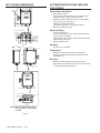
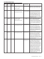
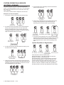
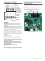
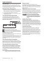
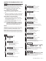
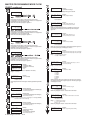
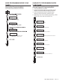
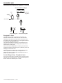
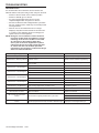
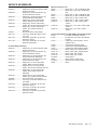
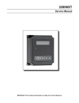
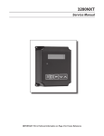
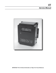
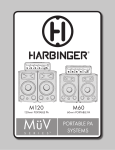
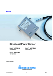
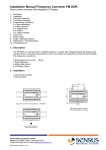
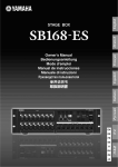
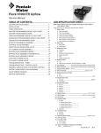
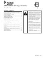
48ES and 51ES NXT Stager Controller
Service Manual
TABLE OF CONTENTS
NXT STAGER DIMENSIONS..................................................2
SYSTEM SPECIFICATIONS 48ES AND 51ES SERIES.........2
SYSTEM DEFINITIONS..........................................................3
SYSTEM OPERATION IN SERVICE
(SYSTEM 14-DEMAND)..........................................................4
TIMER DISPLAY FEATURES.................................................5
NETWORK/COMMUNICATION
CABLES & CONNECTIONS...................................................5
TIMER OPERATION...............................................................6
MASTER PROGRAMMING MODE FLOW CHART................7
USER PROGRAMMING MODE FLOW CHART.....................9
DIAGNOSTIC PROGRAMMING MODE FLOW CHART.........9
PLUMBING DIAGRAMS..........................................................11
SOLENOID USE.....................................................................14
STAGER CONTROLLER, 48ES, NEMA 4 24V/50-60Hz
ASSEMBLY.............................................................................15
STAGER CONTROLLER, 51ES, NEMA 4 24V/50-60Hz
ASSEMBLY.............................................................................16
WIRING DIAGRAM 48/51ES STAGER CONTROLLER.........17
TROUBLESHOOTING............................................................18
SERVICE ASSEMBLIES.........................................................19
IMPORTANT PLEASE READ:
• The information, specifications and illustrations in this
manual are based on the latest information available
at the time of printing. The manufacturer reserves the
right to make changes at any time without notice.
• This manual is intended as a guide for service of the
controller only. System installation requires information
from a number of suppliers not known at the time of
control manufacture. This product should be installed
by a plumbing professional.
• This product must be installed in compliance with all
state and municipal plumbing and electrical codes.
Permits may be required at the time of installation.
• If daytime operating pressure exceeds 80 psi,
nighttime pressures may exceed pressure limits. A
pressure reducing valve must be installed if pressure
exceeds 125 psi. • Do not install the unit where temperatures may drop
below 32°F (0°C) or above 110°F (43°C). • Do not place the unit in direct sunlight. Black units will
absorb radiant heat increasing internal temperatures.
• Do not strike the controller or any of the components.
• Warranty of this product extends to manufacturing
defects. Misapplication of this product may result
in failure to properly condition water, or damage to
product.
• A prefilter should be used on installations in which free
solids are present.
• Correct and constant voltage must be supplied to the
controller to maintain proper function.
43037 Rev D
AU11
NXT STAGER DIMENSIONS
SYSTEM SPECIFICATIONS 48ES AND
51ES SERIES
11.13 [282.7]
8.91 [226.3]
Generic Meter Guidelines
Optional
Solenoid
• Open collector output
• Pulse rate generated must not exceed 100 pulses per
second (100 Hz), or 6,000 pulses per minute
• Support for meter outputs in the range of 1-255 gallons
(25.5 m3) for every 1-255 pulses
Example: 35 gallons/100 pulses
(=3.5 gallons/10 pulses, = 0.35 gallons/1 pulse)
• Meter must operate at 5 VDC
10.50 [266.6]
5.25 [133.4]
1.41 [35.8]
(6X) 1/8" NPT PORT 60 APART
Electrical Rating
1/8" NPT Drain
• 24 VAC Transformers
115 VAC ±20% input, 24 VAC output w/40 VA (maintain
input voltage in this range)
230 VAC ±20% input, 24 VAC output w/108 VA (maintain
input voltage in this range)
• Max Rated Power 15W
[18.62 mm]
* ø 0.733
4 places
ø 0.88
*[22.4
mm]
3.50 [88.9]
2.72 [69]
2.00 [50.8]
2.45 [62.2]
2.75 [69.9] 2.75 [69.9]
4.00 [101.6]
2.06 [52.3]
1/8" NPT Filtered Inlet
48ES STAGER
6.42 [163.1]
1.25 [31.7]
Humidity
6.00 [152.4]
(4X) R.16 [4]
(4X) .19 [4.8]
• 95% RH, non-condensing
Temperature
• Maximum control fluid temperature 140°F (60°C)
• Operate where ambient temperatures are above 32°F
and below 110°F
11.13 [282.7]
Pressure
• Maximum control fluid pressure 125 psi (8.5 bar)
• Control fluid can be either water or air and must be equal
to or greater than system pressure.
.32 [8.1]
1/8" NPT Drain
1.75 [44.4]
1/8" NPT Filtered Inlet
(8X) 1/8" NPT - 45 APART
1/8" NPT Drain
[18.62 mm]
* ø 0.733
4 places
ø 0.88
*[22.4
mm]
51ES STAGER
*NOTE: Drill as required. These holes will only be drilled at factory if required.
Figure 1
2 • NXT Stager Controller AU11
SYSTEM DEFINITIONS
System
Number
System
Description
# of
Tanks/
Controls
4
Single Unit
1
Type
Time Clock: No Meter
Immediate: One Meter
Service Outlet Valve
Controlled by...
Operation Discussion
Stager
(no solenoid required)
Single tank configuration. During
Regeneration no water available to service
unless optional bypass valve #2A installed.
Stager
(no solenoid required)
All tanks in parallel supplying treated water.
Each unit in the system will have its own
flow meter/sensor input. The control will
delay the start of Regeneration if another
unit is already in Regeneration. Once that
unit has completed a Regeneration cycle,
and has returned to Service,the unit with
longest regeneration queue time will begin
Regeneration. No more than one unit will be
in Regeneration at a time.
Stager
(no solenoid required)
All tanks in parallel supplying treated water.
Only #1 control will monitor flow meter/
sensor input. When a regeneration is
required for the system, it will regenerate
valve address #1 first, immediately followed
by #2, then #3, then #4 if installed. No more
than one unit will be in Regeneration at a
time.
Solenoid
(plug stager port 2)
One tank online supplying treated water,
one tank in Standby. Only #1 control
will monitor its flow meter/sensor input.
Regeneration of a unit will begin after the
other control has left Standby and returned
to Service. When the Regeneration cycle
is complete, the regenerated unit will enter
Standby. Standby on each tank is controlled
by a solenoid connected to the service
outlet valve of that tank.
Solenoid
(plug stager port 2)
One, two, or three tanks online supplying
treated water, one tank in Standby. Meter/
sensor input is required on each tank.
Regeneration of a unit will begin after the
other control has left Standby and returned
to Service. When the Regeneration cycle
is complete, the regenerated unit will enter
Standby. Standby on each tank is controlled
by a solenoid connected to the service
outlet valve of that tank.
Solenoid
(plug stager port 2)
Meter input is required on each tank. Unit
#1 will begin In Service with #2, #3, and
#4 (if installed) will begin in Standby. At
least one unit is In Service at all times.
When flow rate to the Primary Service Unit
increases to a user specified rate, the next
unit in sequence will move from Standby to
Service. As the flow rate falls below the user
specified rate subsequent tanks will return
to Standby. When the Primary Service Unit
regenerates, the next unit in sequence
will become the new Primary Service Unit.
As each units capacity is reached the
controller will initiate a Regeneration of that
unit. Depending on the number of units
in the system, and flow rate demand the
regenerated unit will then be placed either
into Standby or Service. Only one unit will
be in Regeneration at a time.
Delayed: One Meter
Remote Signal Start: No Meter
5
Interlocked
2, 3, or 4
Immediate: All Meters
Remote Signal Start: No Meter
6
Series
Regeneration
2, 3, or 4
Immediate: One Meter
Delayed: One Meter
Remote Signal Start: No Meter
7
9
14
Twin
Alternating
2
Multiple Tank
Alternating
2, 3, or 4
Demand
Recall
2, 3, or 4
Immediate: One Meter
Remote Signal Start: No Meter
Immediate: All Meters
Remote Signal Start: No Meter
Immediate: All Meters
NXT Stager Controller AU11 • 3
SYSTEM OPERATION IN SERVICE
(SYSTEM 14-DEMAND)
The system operates as part of a multi-tank regeneration
system. This example applies to either a 2, 3 or 4 tank system.
Each tank in the system will have an active flow meter input,
even in Standby.
The number of tanks In Service depends on the flow rate.
5. The third tank returns to Standby as demand decreases
past the second trip point.
Examples of a Four-Unit System:
1. One Tank is In Service at all times (the "primary tank").
1
2
3
Standby
Flow Split Between
Two Meters
1
2
In Service
(Primary Tank)
3
6. Tanks return to Standby due to decreased total flow rate
and trip points programmed. The tank with the most
remaining volume will be the first to go into Standby.
4
Standby
2. The total flow rate to the primary tank increased past the
first trip point programmed rate. The flow stayed past
the trip point delayed time. The next tank (least volume
remaining) changes from Standby to In Service. This then
splits the total flow between two meters.
1
2
Full Capacity
4th in Standby
(Primary Valve)
1
2
3
4
In Service
First Trip Point
(Primary Valve)
4
Standby
3
3/4 Capacity
1/2 Capacity
3rd in Standby 2nd in Standby
4
1/4 Capacity
1st in Standby
7. The primary tank regenerates. The next tank with the least
remaining volume becomes the new primary tank. The tank
with the next least volume remaining will be the first trip
point programmed rate. Tanks continue operating in this
order.
System Operation in Regeneration:
Total Flow Split
Between Two Meters
3. The flow rate demand decreased below the first trip point.
The tank returns to Standby.
1
2
Flow Rate Demand
Below First Trip Point
(Primary Valve)
3
4
Standby
4. Total flow rate demand increased past a second trip point
programmed rate. The second and third tank (least volume
remaining) changes from Standby to In Service. The total
flow is split between the three meters.
1
2
3
4
Standby
Flow Split Between
Three Meters
4 • NXT Stager Controller AU11
1
2
3
4
Full Capacity
4th in Standby
3/4 Capacity
3rd in Standby
1/2 Capacity
First Trip Point
Programmed Rate
1/4 Capacity
New Primary Tank
If two tanks are In Service and both reach
Volume Remaining = 0, the other two tanks will shift from
Standby to In Service. The lead tank with
Volume Remaining = 0 will start Regeneration. The second
tank with Volume Remaining = 0 will enter Standby. If flow
increases past the trip point a third tank needs to enter In
Service. The tank in Standby with Volume Remaining = 0 will
shift into In Service to maintain a steady flow. Operating for
extended periods in this mode may degrade the water quality.
TIMER DISPLAY FEATURES
Valve State
(SBY, SRV, INI, LCK)
Valve
Address
Flow
System
Indicator
Number
Time
of Day
Display Screen
Time of Day alternates
with Error Screen
Example: Valve #, Volume
Remaining, Errors
Volume Remaining
Diagnostic Button
View Flow Rate, Peak Flow
Rate, Totalizer, Hours
Between Last Two
Regenerations, Hours Since
Last Regeneration, Adjustable
Volume Remaining, Valve
Position, Send & Receive
Errors, Software Version
Extra Cycle Button
Cycle Valve in
Regeneration/Cycle
Programming Steps
Shift Button
Adjusts Values to the Left
NETWORK/COMMUNICATION CABLES
& CONNECTIONS
Use a CAT5 Network/Communication cable.
Connect the network/communication cable to either port before
programming.
The maximum cable length between timers is 100 feet.
Connect units together from one communication port to the
next communication port. The order is not important.
Ground
Lock
Communication Ports
Regen
Up Button
Adjusts Values Up
Down Button
Adjusts Values Down
Status LED
Figure 1
Valve State
INI (Initializing) - INI will display on the screen for 30 to
45 seconds when initializing after a power failure reset or
programming.
RGQ (Regeneration Queued) -RGQ indicates that the reserve
has been entered in a delayed system and regeneration has
been queued. When in the main screen, press the Extra Cycle
button to toggle service (SRV) with RGQ.
Service (SRV) - SRV will display when the unit is In Service.
LCK (Lock) - Lock will be displayed when contact closure is
applied across the interlock terminals on the circuit board. See
the “Network/Communication Cables & Connections” section of
this manual.
Figure 2Current NXT Circuit Board
LED Status Lights
Blue LED - Illuminates while the unit is In Service and no
errors exist. The unit will always be In Service unless a
regeneration trigger has occurred (green LED light will be
displayed). A blinking blue light indicates the timer is In Service,
and queued for regeneration.
Green LED - Illuminates when the unit is in Regeneration
mode. A blinking green light indicates the timer is in Standby,
and not in Regeneration.
Red LED- Illuminates when there is an error.
Flow Indicator
A rotating line (appearing as a rotating star shape) will display
on the screen when flow is going through the meter.
NXT Stager Controller AU11 • 5
TIMER OPERATION
Set Time of Day
Hold the Up or Down button to change time. While in time
change mode press Shift to adjust next digit over. On multiple
tank systems change time on #1 control only. All other controls
in system will mirror the time on control #1.
Manually Initiating a Regeneration
1. When timer is In Service or Stand By, press the Extra Cycle
button on the main screen for five (5) seconds to force a
manual regeneration if another unit is not in Regeneration.
2. The timer reaches Regeneration cycle Step #1.
3. Press the Extra Cycle button once to advance valve to the
next Regeneration cycle.
Timer Operation During Regeneration
In the Regeneration cycle step display, the timer shows
the current Regeneration cycle number the valve is in, or
has reached, and the time remaining in that step. Once all
regeneration steps are complete the timer returns to In Service
and resumes normal operation.
Remote Lockout
The timer does not allow the unit/system to go into
Regeneration until the regeneration lockout input signal to the
unit is cleared. This requires a contact closure to activate the
lockout. The recommended gauge wire is 20 with a maximum
length of 500 feet.
Regeneration Day Override Feature
If the Day Override option is turned on and the actual number
of days since last regeneration exceeds the set regeneration
day override value, the Regeneration cycle starts. If other units
are in regeneration, it is added to a regeneration queue. This
occurs regardless of the remaining volume available.
WARNING: This unit is not designed to drive/power
external devices. Transformer must be
grounded. Ground wire must be terminated
to the back plate where grounding label is
located.
Auxiliary Relay Output
The Auxiliary Relay Output on the circuit board can be
programmed to be closed during a window of time within the
regeneration sequence. The Aux Relay Output Start time sets
the turn-on time referenced to the start of regeneration. The
Aux Relay Output End time sets the turn-off time referenced to
the start of regeneration. The Auxiliary Relay Output shares the
same relay as the Chemical Pump Output. See wiring diagram
for connection information.
Chemical Pump Output
Example: 12 minutes remaining in Cycle 1
Press the Extra Cycle button during a
Regeneration Cycle to immediately advance the
valve to the next cycle and resume normal timing.
Flow Meter Equipped Timer
During normal operation the Time of Day screen alternates with
the Error screen (if errors are present).
As treated water is used, the Volume Remaining display counts
down from the calculated system capacity to zero. When zero
is reached a Regeneration cycle begins if no other units are in
regeneration.
Timer Operation During Programming
The timer enters the Program Mode in Standby or Service
Mode as long as it is not in regeneration. While in the Program
Mode the timer continues to operate normally monitoring water
usage. Timer programming is stored in memory permanently.
Timer Operation During A Power Failure
During a power failure all timer displays and programming are
stored for use upon power re-application. The timer retains
all values, without loss. The timer is fully inoperative and any
calls for regeneration are delayed. The timer, upon power
re-application, resumes normal operation from the point that it
was interrupted.
NOTE: A flashing Time of Day display indicates a power
outage. Hold the Up or Down button to reset time.
6 • NXT Stager Controller AU11
When the Chemical Pump Output feature is enabled, the
control will calculate volume of water used and close the
relay when the set CPO Aux Relay Volume is reached. Once
activated, the relay will stay closed for the amount of time set
in CPO Aux Relay Time. The Chemical Pump Output only
functions while in service, and the CPO volume is reset to zero
each regeneration. The Chemical Pump Output shares the
same relay as the Auxiliary Relay Output. See wiring diagram
for connection information.
SYSTEM SIZE:
2 VALVES
MASTER PROGRAMMING MODE FLOW
CHART
CAUTION Before entering Master Programming, please
contact your local professional water dealer.
When the Master Programming Mode is entered, parameters
can be set to make the timer(s) function as needed.
NOTE: Depending on current option settings, some
displays cannot be viewed or set.
Entering Master Programming Mode
1. Press and hold the Shift and Up buttons for 5 seconds.
OR
2. Set the time of day display to 12:01 PM or 12:01HR. Press
and hold Up or Down buttons to set the time. Then press
the Up and Down buttons at the same time for 5 seconds.
Exiting Master Programming Mode
1. Press the Extra Cycle button once per display until all
are viewed. Master Programming Mode is exited and the
normal display screen appears.
2. To exit the Master Programming Mode without saving
changes, press the Diagnostic button.
NOTE: If no keypad activity is made for 5 minutes while
in the Master Programming Mode, or if there is a
power failure, no changes will be saved, and the
unit will go back to the main display screen.
Resets
Soft Reset: Press and hold the Up and Down buttons for 25
seconds until 12:00PM (or 12:00HR) appears. This resets all
parameters except for the flow meter totalizer volume.
Master Reset: Hold the Extra Cycle button while powering up
the unit. This resets all of the parameters in the unit. Check
and verify the choices selected in Master Programming Mode.
Example:
2 Valves in the System (Default)
Options: 2 Valves in the System (Default)
3 Valves in the System
4 Valves in the System
Range: 2 to 4 Valves in the System
NOTE: This screen will not display for System Type 4.
REGEN TYPE:
TIME CLK DELAYED
Example:
Time Clock Delayed (Default)
Options: Time Clock Delayed (System 4 Only) (Default)
Meter Immediate (All System Types)
Meter Delayed Fixed Reserve (Systems 4 & 6 Only)
VALVE TYPE:
STAGER-NOTCH CAM
Example:
Stager - Notch Cam (Default)
Options: 2750
2850
2900
3150
3900
Stager - Notch Cam (Default)
REMOTE SIGNAL
START:OFF
Example:
Off (Default)
Options: 00:06:00 (Hours:Munutes:Seconds)
Range: 1 second to 99 minutes (1 hour, 39 minutes)
NOTE: This display will not be viewed in System 14.
DISPLAY FORMAT:
US-GALLONS
Example:
U.S. Gallons (Default)
Options: U.S. - Gallons (Default)
EU-Metric - Liters (Metric)
NOTE: In U.S. - Gallons mode, the display will be in 12-hour time.
NOTE: In European Units - Liters (Metric) mode, the display will be in
24-hour time.
UNIT CAPACITY:
0300000
GRAINS
Example:
0300000 Grains (Default)
Options: Grains (in U.S. Format) (Default)
Grams (in Metric Format)
Range: 1 to 9,900,000 Grain Capacity in U.S. Format
1.0 to 190,000 grams CaCO3 Capacity in Metric Format
NOTE: Use the Shift button to move to the left.
CAPACITY SAFETY
FACTOR:
00%
Example:
00% (Default)
Range: 0 to 50%
NOTE: Use the Shift button to move to the left.
SELECT LANGUAGE:
ENGLISH
Example:
English
Options: English
Espanol
Portugues
Deutsch
Francais
SYSTEM TYPE:
SINGLE UNIT
4
Example:
System Type 4, Single Unit
Options: System 4 (single unit)
System 5 (2-4 units) - Parallel Interlock
System 6 (2-4 units) - Parallel Series Regeneration
System 7 (2 units) - Alternating
System 9 (2-4 units) - Alternating
System 14 (2-4 units) - Demand Recall
VALVE ADDRESS:
#2
Example:
Valve Address #2 (Second Control Valve) (Default)
Options: Valve Address #1 (First Control Valve)
Valve Address #2 (Second Control Valve) (Default)
Valve Address #3 (Third Control Valve)
Valve Address #4 (Fourth Control Valve)
NOTE: This screen will not display for System Type 4.
SYSTEM SIZE:
2 VALVES
Example:
2 Valves in the System (Default)
Options: 2 Valves in the System (Default)
3 Valves in the System
4 Valves in the System
Range: 2 to 4 Valves in the System
NOTE: This screen will not display for System Type 4.
REGEN TYPE:
TIME CLK DELAYED
Example:
Time Clock Delayed (Default)
Options: Time Clock Delayed (System 4 Only) (Default)
FEED WATER
HARDNESS: 15 GPG
Example:
15 GPG (U.S. Format) (Default)
Range: 1 to 199 Grains/Gallon (U.S. Format)
2 to 199 miligrams CaCOs/L (Metric Format)
NOTE: Use the Shift button to move to the left.
NOTE: This screen will only display on the lead unit for System Types 6 & 7.
For all other System Types, it will display for all units.
TRIP POINT 1:
000 gpm
1 to 997 gpm
1 to 3997 Lpm
NOTE: Display will only appear on the master timer and it must be
programmed as valve position #1. Use the Shift button to change each
decimal position.
NOTE: This screen will only display for System 14.
TRIP DELAY 1:
30 SECONDS
NOTE: Display will only appear on the master timer and it must be
programmed as valve position #1. Use the Shift button to move one space
to the left.
NOTE: This screen will only display for System 14.
TRIP POINT 2:
gpm
NXT Stager Controller AU11 • 7
2 to 998 gpm
1 to 3997 Lpm
CYCLE 4 OFF
TRIP DELAY 1:
30 SECONDS
CYCLE 4 00:12:00
MASTER
PROGRAMMING MODE FLOW
NOTE: Display will only appear on the master timer and it must be
programmed as valve position #1. Use the Shift button to move one space
CHART
continued
to the
left.
NOTE: This screen will only display for System 14.
CYCLE 5 OFF
Example:
Off (Default 48-00 Stager)
Example: Refill
00:12:00 (Default 51-09 Stager)
(Hours:Minutes:Seconds)
Example:
Off (Default 51-09 Stager)
NOTE: This screen will only display when cycle 4 is not OFF.
TRIP POINT 2:
gpm
AUXILIARY RELAY:
DISABLED
2 to 998 gpm
1 to 3997 Lpm
NOTE: Display will only appear on the master timer and it must be
programmed as valve position #1. System size must be 3 or 4 to appear. Use
the Shift button to move one space to the left.
NOTE: This screen will only display for System 14.
Options: Enabled
Disabled (Default)
AUX RELAY OUTPUT
START 1 00:00:00
Range:
TRIP DELAY 2:
Example:
Auxiliary Relay is Disabled
Example:
Auxiliary Relay Output Start 1 at
0 hours, 0 minutes, & 0 seconds
00:00:00 to 18:00:00
NOTE: Only displayed if Auxiliary Relay is enabled in previous screen.
Auxiliary Relay will only display if Chemical Pump is OFF for System
Types 6 & 7.
30 SECONDS
NOTE: Display will only appear on the master timer and it must be
programmed as valve position #1. System size must be 3 or 4 to appear. Use
the Shift button to move one space to the left.
NOTE: This screen will only display for System 14.
AUX RELAY OUTPUT
END 1 00:00:00
Range:
Example:
Auxiliary Relay Output End 1 at
0 hours, 0 minutes, & 0 seconds
00:00:00 to 18:00:00
TRIP POINT 3:
gpm
CHEMICAL PUMP:
DISABLED
3 to 999 gpm
1 to 3997 Lpm
NOTE: Display will only appear on the master timer and it must be
programmed as valve position #1. System size must be 4 to appear. Use the
Shift button to move one space to the left.
NOTE: This screen will only display for System 14.
Options: Enabled
Disabled (Default)
NOTE: This screen will only display on the lead unit for System Types 6 & 7.
For all other System Types, it will display for all units.
CPO AUX RELAY
VOLUME:
000 9
TRIP DELAY 3:
30 SECONDS
Range:
CPO AUX RELAY
TIME:
00:00:00
REGENERATION DAY
OVERRIDE:01 DAYS
Example:
Off (Default for Meter)
On (Default for Time Clock)
Example:
1 Day
Options: Off (Default for Meter) or On (Default for Time Clock)
Range: 1 to 99 Days
REGENERATION
TIME:
02:00AM
Example:
2:00 A.M. (Default)
Options: A.M. (U.S. Format)
HR (Metric Format)
NOTE: Regeneration time will not appear unless Regeneration Day Override
is on.
Range:
CYCLE 2 01:00:00
Example: Backwash
00:10:00 (Default 48-00 Stager & 51-09 Stager)
(Hours:Minutes:Seconds)
Example: Brine
01:00:00 (Default 48-00 Stager & 51-09 Stager)
(Hours:Minutes:Seconds)
Options: 01:00:00 for Conditioner for the 48-00 Stager & 51-09 Stager (Default)
00:00:00 for Filter for the 48-00 Stager
FLOW METER:
1.0 PADDLE
CYCLE 4 OFF
CYCLE 4 00:12:00
Example: Fast Rinse
00:10:00 (Default 48-00 Stager & 51-09 Stager)
(Hours:Minutes:Seconds)
Example:
Off (Default 48-00 Stager)
Example: Refill
00:12:00 (Default 51-09 Stager)
(Hours:Minutes:Seconds)
8 • NXT Stager Controller AU11
CYCLE 5 OFF
Example:
Off (Default 51-09 Stager)
Example:
1.0 Paddle Flow Meter
Options: 1.0 Paddle
1.0 Turbine
1.5 Paddle
1.5 Turbine
2.0 Paddle
3.0 Paddle
Generic
NOTE: Default flow meter type is based on the valve type. This screen will
only display on the lead unit for System Types 6 & 7. All other system types
it will display for all units.
Range:
Example:
Maximum Flow Rate of 0 gpm
20 - 2000 gpm (U.S. Format)
20 - 2000 Lpm (Metric Format)
NOTE: Only displayed if “Generic” is chosen for the flow meter.
ADD 01 GALLONS
EVERY 001 PULSES
Example:
Add 1 Gallon for Each Pulse in U.S. Format
Options: Gallons (U.S. Format)
Liters (Metric Format)
Range:
CYCLE 3 00:10:00
Example:
Each time chemical pump relay is on, run for
30 seconds (00:00:30)
00:00:00 to 02:00:00
MAXIMUM FLOW
RATE:
0000 gpm
CYCLE 1 00:10:00
Example:
Energize Chemical Pump relay every 50 gals (50)
Energize Chemical Pump relay every 200 L (200)
1 to 999 gallons in U.S. Format
1 to 9999 L in Metric Format
NOTE: Display will only appear on the master timer and it must be
programmed as valve position #1. System size must be 4 to appear. Use the
Shift button to move one space to the left.
NOTE: This screen will only display for System 14.
REGENERATION DAY
OVERRIDE:OFF
Example:
Chemical Pump is Disabled
1 - 99 Gallons (U.S. Format)
0.1 - 09.9 L (Metric Format)
Pulses: 1 - 99
NOTE: Only displayed if “Generic” is chosen for the flow meter.
PROGRAMMING UNIT
PLEASE WAIT...
Example:
Master Programming Mode is Exiting
USER PROGRAMMING MODE FLOW
CHART
DIAGNOSTIC PROGRAMMING MODE
FLOW CHART
Entering User Programming Mode
Entering Diagnostic Programming Mode
Hold the Up and Down buttons for 5 seconds.
1. Push and release the "D" button.
2. Press the Extra Cycle button once per display until all
displays are viewed and Normal Display is resumed.
3. Push and release the"D" button at anytime during
diagnostic mode and the timer will exit the mode.
4. Depending on the current controller programming, certain
displays may not be able to be viewed or set.
FEED WATER
HARDNESS:
gpg
Options: U.S. Format
Metric Format
[gpg]
[mgL]
CURRENT FLOW
RATE:
REGENERATION DAY
Options: U.S. Format
Metric Format
0 gpm
Explaination: Flow rate at this time.
OVERRIDE: OFF
[OFF] = default
[OFF] = default
PEAK FLOW RATE:
0 gpm
Explaination: Peak flow since last regeneration.
REGENERATION DAY
OVERRIDE:99 DAYS
TOTALIZER:
130 g
Explaination: Gallons at the outlet since installation.
REGENERATION
TIME:
02:00AM
Options: U.S. Format
Metric Format
LAST TWO REGENS:
0 HOURS
[02:00AM] = default
[02:00] = default
Explaination: Hours between the last regeneration and the one before it.
LAST REGEN
0 HOURS
Explaination: Hours since last regeneration.
VOLUME REMAIN:
1000 g
Explaination: Volume remaining; can be adjusted.
VALVE ADDRESS
#2
Explaination: Controller unit number.
VERSION:
X.XX
Explaination: Installed software level of the controller in use.
NXT Stager Controller AU11 • 9
10 • NXT Stager Controller AU11
Valve Address
Select Language
System Size
Regen Type
Valve Type
Regenerant Flow
Remote Signal Start
Display Format
Unit Capacity
Capacity Safety Factor
Feed Water Hardness
Trip Point 1
Trip Delay 1
Trip Point 2
Trip Delay 2
Trip Point 3
Trip Delay 3
Regeneration Day Override
Regeneration Time
Cycle 1
Cycle 2
Cycle 3
Cycle 4
Cycle 5
Auxiliary Relay
Aux Relay Output Start
Aux Relay Output End
Chemical Pump
CPO Aux Relay Volume
CPO Aux Relay Time
Flow Meter
Generic
Maximum Flow Rate
Add _ _ _ Gallons or Liters
Every _ _ _ Pulses
Notes
System Type
x
x
x
x
x
x
x
x
x
o
x
x
x
x
x
x
c
c
x
c
c
x
x
a
a
a
x
x
x
x
x
x
x
x
x
x
x
x
x
c
c
x
o
x
x
x
x
x
x
c
c
x
c
c
x
x
a
a
a
x
x
x
x
x
x
x
x
x
4
Metered
Delayed
x
o
x
x
x
x
x
x
c
c
x
c
c
x
x
a
a
a
1
x
x
x
x
x
x
x
x
x
x
x
o
x
x
x
x
x
x
c
c
x
c
c
x
x
a
a
a
x
x
x
x
x
x
x
x
2
x
x
o
x
x
x
x
x
x
c
c
x
c
c
x
x
a
a
a
x
x
x
x
x
x
x
x
3
x
5
Interlock
x
o
x
x
x
x
x
x
c
c
x
c
c
x
x
a
a
a
x
x
x
x
x
x
x
x
4
x
x
o
x
x
x
x
x
u
c
c
u
c
c
x
x
a
a
a
1
x
x
x
x
x
x
x
x
x
x
x
x
x
x
x
x
c
c
x
x
x
x
x
x
x
x
c
c
x
x
x
3
x
x
x
x
2
x
6
Series
x
x
x
x
x
x
c
c
x
x
x
x
4
x
x
o
x
x
x
x
x
u
c
c
u
c
c
x
x
a
a
a
1
x
x
x
x
x
x
x
x
x
x
o
x
x
x
x
x
x
c
c
x
x
x
x
x
x
x
2
x
7
Alternating
x
o
x
x
x
x
x
x
c
c
x
c
c
x
x
a
a
a
1
x
x
x
x
x
x
x
x
x
x
x
o
x
x
x
x
x
x
c
c
x
c
c
x
x
a
a
a
x
x
x
x
x
x
x
x
2
x
x
o
x
x
x
x
x
x
c
c
x
c
c
x
x
a
a
a
x
x
x
x
x
x
x
x
4
x
x
x
x
x
x
x
x
x
x
x
x
o
x
x
x
x
x
x
c
c
x
c
c
x
x
a
a
a
1
x
x
x
x
x
x
o
x
x
x
x
x
x
c
c
x
c
c
x
x
a
a
a
x
x
x
x
x
x
x
2
x
x
o
x
x
x
x
x
x
c
c
x
c
c
x
x
a
a
a
x
x
x
x
x
x
x
3
x
14
Demand
Recall
x
o
x
x
x
x
x
x
c
c
x
c
c
x
x
a
a
a
x
x
x
x
x
x
x
4
x
20 - 2000 GPM
1 - 255 Gallons
1 - 255
20 - 2000 LPM
001 - 255 Liters
1 - 255
Liters
1 thru 4
English, Espanol, Portugues, Deutsch, Francais
1 thru 4
Time Clock, Metered Delayed, Metered Immediate
2750, 2850, 2900, 3150, 3900, Stager
Downflow, Upflow, Upflow Fill First
Off, 00:00:01 - 01:39:00
US - Gallons
EU - Metric-Liters
1 - 9900000 Grains
1 - 198000 gCaCO3
0- 50%
1 - 199 Grains/Gallons
1 - 1999 mgL
0 - 997gpm
0 - 3997 Lpm
30 - 99 Seconds
30 - 99 Seconds
Trip Point 1 + 1 - 998 gpm Trip Point 1 + 1 - 3998 Lpm
30 - 99 Seconds
30 - 99 Seconds
Trip Point 2 + 1 - 999 gpm Trip Point 2 + 1 - 3999 Lpm
30 - 99 Seconds
30 - 99 Seconds
Off, 1 - 99
12:00 a.m. - 11:59 p.m.
00:00 - 23:59 Hour
00:00:00 - 04:00:00
Off, 00:00:00 - 04:00:00
Off, 00:00:00 - 04:00:00
Off, 00:00:00 - 04:00:00
Off, 00:00:00 - 04:00:00
Enabled, Disabled
00:00:01 to Total Regeneration Time - 1
Start Time + 1 to Total Regeneration Time
Enabled, Disabled
1 - 999 gallons
0001 - 9999 Liters
00:00:01 - 02:00:00
00:00:01 - 02:00:00
1" 1.5" Paddle or Turbine, 2" Paddle, 3" Paddle, Generic
Gallons
Programming Parameter Ranges
a - If Generic Flow Meter is chosen, then programming parameters will be viewed.
c - All Relay Output parameters programming will be viewed if Enabled.
u - If Auxiliary Relay is Enabled then Chemical Pump Relay will not be viewed or if Chemical Pump Relay is Enabled then Auxiliary Relay will not be viewed.
x
o
x
x
x
x
x
x
c
c
x
c
c
x
x
a
a
a
x
x
x
x
x
x
x
x
3
x
9
Alternating
o - Regeneration Time will only be viewed if Regeneration Day Override is used.
x
4
Metered
Immediate
x
4
Time
Clock
NXT Multi Language
Programming Parameters and Ranges
PLUMBING DIAGRAMS
Stager Operation
Stagers are motor driven, rotary multi-port valves used to
control a set of valves in a predefined sequence. They function
by internally connecting inlet pressure to a defined set of
control ports and allowing other control ports be vented through
a drain. Control ports are used to open and close valves in a
preset sequence. As the stager advances to various positions,
different valves are open and closed in a system. The control
port pressure and vent sequence is preset at the factory and
cannot be field altered.
4 Position Softener (48-00 Stager)
Stager Installation
1. Connect a constant pressure water or air source to the 1/8"
NPT stager inlet. Control fluid pressure must be equal to or
greater than system pressure. To ensure long trouble free
operation, a 100 micron filter in the control pressure line is
recommended.
2. Stager drain port should be left open or discharged to
unrestricted or open drain. DO NOT plug or restrict drain
port.
3. Connect the 1/8" NPT control ports to appropriate valves.
Refer to tubing schematic provided in the Plumbing
Diagrams section of this manual. Tubing inside diameter
should be 1/8" or larger.
Optional Hard
Water Bypass Valve
Inverted Type Stagers
Drain Line Flow
Control not shown
Stagers that are ordered inverted would be used on systems
with all normally closed valves. Inverted Stagers send pressure
signals to open valves and vent signals to close valves.
B
A
Note A: All valves normally open except optional valve 2A.
Note B: Inverted Stager types will have these ports pressurized.
Inverted Stager to be used with all valves normally closed except
optional valve 2A.
NXT Stager Controller AU11 • 11
PLUMBING DIAGRAMS continued
4 Position Filter (48-00 Stager)
5 Position Softener w/Timed Brine Refill
(51-09 Stager)
Customer
Supplied Valve
Optional Hard
Water Bypass Valve
Optional Hard
Water Bypass Valve
Drain Line Flow
Control not shown
Drain Line Flow
Control not shown
Plugs installed
at factory
4 POSITION FILTER
Installer to plug (with
PN1071903)for filter operation
B
B
A
C
Note A: All valves normally open except optional valve 2A.
Note B: Inverted Stager types will have these ports pressurized.
Inverted Stager to be used with all valves normally closed except
optional valve 2A.
Note C: Program Cycle 2 time to 00:00:00 for filter operation.
12 • NXT Stager Controller AU11
A
Note A: All valves normally open except optional valve 2A.
Note B: Inverted Stager types will have these ports pressurized.
Inverted Stager to be used with all valves normally closed except
optional valve 2A.
PLUMBING DIAGRAMS continued
Multiple Tank 4 Position Softener (48-00 Stager)
3A
5A
EJECTOR
3B
5B
RAW WATER
BRINE
1A
1B
4A
4B
To Additional Tanks
As Required
INLET
2A
2B
6A
6B
SERVICE
UNIT A
UNIT B
DRAIN
NOTE: All valves normally open, pressure to close.
NOTE: Valve 2 for each tank is controlled by solenoid for
system 7, 9, 14
DRAIN LINE FLOW
CONTROL NOT SHOWN
Multiple Tank 5 Position Softener (51-09 Stager)
Customer Supplied
Check Valve
Customer Supplied
Check Valve
Ejector
Ejector
To Brine Tank
To Brine Tank
3A
3B
5B
5A
1B
1A
To Additional Tanks
As Required
INLET
7A
7B
4A
4B
To Brine Refill
To Brine Refill
6A
2A
6B
2B
SERVICE
UNIT A
DRAIN
UNIT B
DRAIN LINE FLOW
CONTROL NOT SHOWN
NOTE: All valves normally open, pressure to close.
NOTE: Valve 2 for each tank is controlled by solenoid for
system 7, 9, 14
NXT Stager Controller AU11 • 13
SOLENOID USE
Solenoids only required for Systems 7, 9 and 14
Series 48-00/51-09 Stager
Installer to
Plug Port 2
Drain
Solenoid
Valve
3
Inlet Pressure
1 2
2
3
2
1
1
Flow
Flow
Solenoid Energized
3
Solenoid De-energized
Energized To Close
The NXT Stager control can operate an optional 24 VAC
solenoid to control when a tank is off line. This solenoid is
electrically connected to the "lower drive" connection on the
circuit board, and control pressure is run through the solenoid
to the service outlet diaphragm valve.
The solenoid installed at the factory is a universal type. It is
plumbed in an energize to close configuration when service
outlet valve is normally open.
When a tank enters Regeneration or Standby the solenoid is
energized. Pressure from solenoid port 1 passes to port 2. The
diaphragm valve #2 will close.
When a tank enters In Service the solenoid is de-energized.
The inlet pressure to solenoid port 2 is stopped. The
diaphragm valve is vented through solenoid port 2 to port 3
(drain). The valve #2 opens.
Inverted Stagers Only - Energize to Open
If the service outlet vavle is normally closed, connect constant
pressure source to solenoid port 3. Connect solenoid port 2 to
service outlet valve. Solenoid port 1 is drain.
14 • NXT Stager Controller AU11
STAGER CONTROLLER, 48ES, NEMA 4
24V/50-60Hz ASSEMBLY
47
41
30 33
34
31
AUX 1 (RED)
38
35
39
HOFFMAN PARTS BAG
SCALE 1:4
26
CYCLE (WHITE)
50
32
47
44
3
42
43
3
37
1
48
2
40
28
3
27
51
7
25
49
ISO FRONT VIEW
16
SCALE 1:4
29
24
23
4
36
45
22
21
18
17
19
46
5
KIT BR61764
11
SCALE 1:4
6
8
9
14
15
12
20
10
TO METER
NOT CONNECTED
12
61803 Rev D
13
BOTTOM DETAIL VIEW
SCALE 1:2
Item No.
QTY
Part No.
Description
Item No.
QTY
Part No.
Description
1������������������ 1��������� 43001������������������� Motor, 24V, 50/60Hz, 5/8 RPM
33���������������� 1��������� 1073732��������������� Label, Terminal Strip, 1-10
2������������������ 1��������� 1070436��������������� Plate, Motor MTG, Stagers
34���������������� 1��������� 43094-01�������������� Enclosure, 48ES, NEMA 4
3������������������ 6��������� 1075746��������������� Screw, 6-32 x 1/4", Phil
35���������������� 1��������� 43093������������������� Panel, A10P, 8" x 6" Modified
4������������������ 4��������� 1072371��������������� Screw, 6-32 x .375, RD.HD, SS
36���������������� 1��������� 43046*������������������ Keypad Label Assy, XT, NEMA 4
5������������������ 1��������� 1075737��������������� Gasket, Stager MTG, 48
37���������������� 1��������� 1070649��������������� Solenoid, N1, 24/60
6������������������ 1��������� 1071667��������������� O-ring, 2-010, Nitrile
38���������������� 4��������� 42827-04�������������� Stand-off, Plastic, .625"
7������������������ 1��������� 1075454*�������������� Thumb Wheel, Molded
39���������������� 1��������� 42753U*��������������� Circuit Board, XT, ML
8������������������ 1��������� 1074074��������������� Washer, 302, SS
40���������������� 4��������� 43092������������������� Screw, FLT HD, #6-20, TYP-B
9������������������ 1��������� 1070448��������������� Shaft, Stem Assy, 48 Series
41���������������� 1��������� 40941������������������� Harness, Upper Drive
10���������������� 1��������� 1074784��������������� Backplate, 48-00, Brass
42���������������� 1��������� 43090������������������� Washer, Sealing, Conduit, 1/2"
11���������������� 1��������� 1074793��������������� Bonnet, 48, Brass
43���������������� 1��������� 43140������������������� Fitting, NPT 1/2, Conduit
12���������������� 1��������� 1074825��������������� Inlet Strainer, Assy
44���������������� 1��������� 43141������������������� Washer, Lock, 7/8, INT Tooth
13���������������� 3��������� 1075759��������������� Screw, Pan Head, 6-32 x .88"
45���������������� 1��������� 61764������������������� Cable Assy, COM, CAT 5E, NEMA 4
14���������������� 1��������� 1076234��������������� Spring, Wave, 17-7 SS, 48 STGR
46����������������� 1����������19121-09��������������� Meter Cable Assy, NT, 99.5"
15���������������� 1��������� 1074845��������������� Stemplate, 48, -00
47����������������� 4����������1081780���������������� Mount, Cable Tie, 4-Way
16���������������� 1��������� 1076245*�������������� Cam, Cycle, Machined
48����������������� 1����������1072379���������������� Screw, 10-32 x 5/8", RND HD, SS
17���������������� 1��������� 1070437��������������� Plate, Bottom MTG, Stager
49����������������� 1����������1071660���������������� Nut, Hex, 10-32, KEPS
18���������������� 2��������� 1075499��������������� Switch, Micro
50����������������� 1����������43177�������������������� Washer, Lock, #8, INT, 18-8 SS
19���������������� 1��������� 1075455��������������� Switch Spacer, Insulator
51����������������� 1����������1071648���������������� Nut
20���������������� 1��������� 1084171��������������� Gasket, Backplate, 48 Nitrile
21���������������� 2��������� 1073593��������������� Washer, Lock, Internal, #4, SS
1��������� 61500-48/51LNE�� Line Drawing
22���������������� 2��������� 1075757��������������� Machine Screw, 4-40 x 1.00, SS if 2
switches
Not Shown
9��������� 1073701��������������� Tie, Cable, HeyCo VNT#4-18
2��������� 1073702��������������� Wire Tie
3��������� 1073955��������������� Terminal, Ring, #10, 16-14 GA
1��������� 1073875��������������� Wire, Black, 18 AWG
1��������� 1073880��������������� Wire, White, 18 AWG
1��������� 1073874��������������� Wire, Green, 14 AWG
1��������� 43163������������������� Literature, 3214 NXT Stager,S/M
1��������� 43012������������������� Wiring Diagram, 48/51ES
1��������� 61784������������������� Service Kit, 48/51, Timer
1��������� 61783������������������� Service Kit, 48/51, Solenoid
1��������� 1071903��������������� 1/8" NPT Pipe Plug Brass
2��������� 1072389��������������� Screw, 4-40 x 1-3/8" if 3 switches
23���������������� 1��������� 1075453*�������������� Cam, Auxiliary, Blank
24���������������� 2��������� 3014200��������������� Screw, Slotted HX HD, 10-32
25���������������� 2��������� 1078992��������������� Washer, Lock, Internal, #10, SS
26���������������� 1��������� 14202-01�������������� Screw, Hex Washer #8-32 x 5/16
27���������������� 1��������� 43077-00�������������� Label, Dial, STGR, 2 3/8 x 7/8
28���������������� 2��������� 17967-01�������������� Nut, Liquid Tight, HeyCo 3169
29���������������� 2��������� 17967-02�������������� Fitting, Liquid Tight, Black
30���������������� 1��������� 1075538��������������� Terminal Block, 10
31���������������� 2��������� 1072369��������������� Screw, Pan HD, 4-40 x 5/8, SS
32���������������� 1��������� 1076219��������������� Label, Ground, .75 Dia.
*Only sold as Service Assembly
NXT Stager Controller AU11 • 15
STAGER CONTROLLER, 51ES, NEMA 4
24V/50-60Hz ASSEMBLY
30
29
AUX 1 (Red)
20 23
39
21
36
27
24
HOFFMAN PARTS BAG
SCALE 1:4
CYCLE (White)
51
16
22
36
32
3
33
1
31
26
37
2
18
38
17
3
15
52
14
5
28
25
19
ISO FRONT VIEW
SCALE 1:4
13
12
8
11
4
9
35
50
34
10
6
KIT BR61764
SCALE 1:4
43
42
48
40
45
41
7
42
44
46
61804 Rev D
47
BOTTOM DETAIL VIEW
49
Item No.
QTY
Part No.
SCALE 1:2
Description
1������������������ 1��������� 43001������������������� Motor, 24V, 50/60Hz, 5/8 RPM
2������������������ 1��������� 1070436��������������� Plate, Motor MTG, Stagers
3������������������ 6��������� 1075746��������������� Screw, 6-32 x 1/4", Phil
4������������������ 2��������� 1072371��������������� Screw, 6-32 x .375, RD.HD, SS
5������������������ 1��������� 1075454*�������������� Thumb Wheel, Molded
6������������������ 1��������� 1075674��������������� Gasket, Stager MTG, 51, 96
7������������������ 1��������� 1074825��������������� Inlet Strainer, Assy
8������������������ 1��������� 1076243*�������������� Cam, Cycle, Machined
9������������������ 2��������� 1075499��������������� Switch, Micro
10���������������� 1��������� 1075455��������������� Switch Spacer, Insulator
11���������������� 2��������� 1073593��������������� Washer, Lock, Internal, #4, SS
12���������������� 2��������� 1075757��������������� Machine Screw, 4-40 x 1.00, SS
13���������������� 1��������� 1075453*�������������� Cam, Auxiliary, Blank
14���������������� 2��������� 3014200��������������� Screw, Slotted HX HD, 10-32
15���������������� 2��������� 1078992��������������� Washer, Lock, Internal, #10, SS
16���������������� 1��������� 14202-01�������������� Screw, Hex Washer #8-32 x 5/16
17���������������� 1��������� 43078-09�������������� Label, Dial, STGR, 2 3/8 x 7/8
18���������������� 2��������� 17967-01�������������� Nut, Liquid Tight, HeyCo 3169
19���������������� 2��������� 17967-02�������������� Fitting, Liquid Tight, Black
20���������������� 1��������� 1075538��������������� Terminal Block, 10
21���������������� 2��������� 1072369��������������� Screw, Pan HD, 4-40 x 5/8, SS if 2
switches
2��������� 1072389��������������� Screw, 4-40 x 1-3/8" if 3 switches
22���������������� 1��������� 1076219��������������� Label, Ground, .75 Dia.
23���������������� 1��������� 1073732��������������� Label, Terminal Strip, 1-10
24���������������� 1��������� 43093������������������� Panel, A10P, 8" x 6" Modified
25���������������� 1��������� 43046*������������������ Keypad Label Assy, ST, NEMA 4
26���������������� 1��������� 1070649��������������� Solenoid, N1, 24/60
27���������������� 1��������� 42753U*��������������� Circuit Board, XT, ML
28���������������� 4��������� 43092������������������� Screw, FLT HD, #6-20, TYP-B
29���������������� 4��������� 42827-04�������������� Stand-off, Plastic, .625"
30���������������� 1��������� 40941������������������� Harness, Upper Drive
31���������������� 1��������� 43090������������������� Washer, Sealing, Conduit, 1/2"
32���������������� 1��������� 43141������������������� Washer, Lock, 7/8, INT Tooth
16 • NXT Stager Controller AU11
Item No.
QTY
Part No.
Description
33���������������� 1��������� 43140������������������� Fitting, NPT 1/2, Conduit
34���������������� 1��������� 61764������������������� Cable Assy, COM, CAT 5E, NEMA 4
35���������������� 1����������19121-09��������������� Meter Cable ASSY, NT, 99.5"
36���������������� 4����������1081780���������������� Mount, Cable Tie, 4-Way
37���������������� 1����������1072379���������������� Screw, 10-32 x 5/8", RND HD, SS
38���������������� 1����������1071660���������������� Nut, Hex, 10-32, KEPS
39���������������� 1��������� 43094-02�������������� Enclosure, 51ES, NEMA 4
40���������������� 1��������� 1075241��������������� Washer, 302, SS
41���������������� 1��������� 1070438��������������� Shaft, Stem Assy, 51 Series
42���������������� 2��������� 1071903��������������� Male Pipe Plugs
43���������������� 1��������� 1074883��������������� Bonnet, 51, Brass
44���������������� 1��������� 1075647*�������������� Stemplate, 96, Alpha
45���������������� 1��������� 1075242��������������� Spring, Compression
46����������������� 1����������1084172���������������� Gasket, Backplate, 51 & 96 STGRS
47����������������� 1����������1074866*��������������� Backplate, D.V. Nest
48����������������� 1����������1071716���������������� O-ring, EP, ORE-011
49����������������� 4����������1075760���������������� Screw, Machine, #6-32 x 1 1/8
50����������������� 1����������1077824���������������� MTG Plate, BTM, STGR, 51ES
51����������������� 1����������43177�������������������� Washer, Lock, #8, INT, 18-8 SS
52����������������� 1����������1071648���������������� Nut
Not Shown
1��������� 61500-48/51LNE�� Line Drawing
9��������� 1073701��������������� Tie, Cable, HeyCo VNT#4-18
2��������� 1073702��������������� Wire Tie
3��������� 1073955��������������� Terminal, Ring, #10, 16-14 GA
1��������� 1073875��������������� Wire, Black, 18 AWG
1��������� 1073880��������������� Wire, White, 18 AWG
1��������� 1073874��������������� Wire, Green, 14 AWG
1��������� 43163������������������� Literature, 3214 NXT Stager,S/M
1��������� 43012������������������� Wiring Diagram, 48/51ES
1��������� 61784������������������� Service Kit, 48/51, Timer
1��������� 61783������������������� Service Kit, 48/51, Solenoid
*Only sold as Service Assembly
GR
EE
10
4
5
6
7
8
9
3
N/ Y
OW
ELL
BLUE
BROWN
BLUE
BLACK
BLACK
WHITE
GREEN/YELLOW
GREEN/YELLOW
GREEN/YELLOW
R
G
N
EE
/Y
EL
BR43001
24V/50/60, 4 WATT
N.O.
OPTIONAL
AUX CAM
#2
S1
ORANGE
AUX CAM
#1
NEUTRAL
N.O.
(CYCLE CAM)
PROGRAM CAM
UPPER DRIVE
CAN1
PURPLE
ORANGE
BLACK
WT/BLK
YELLOW
SWITCHED HOT
(HOMING CAM)
(SWITCH HOUSING
IS RED)
N.O.
C
NOTES:
1.
SWITCHES SHOWN IN SERVICE.
2.
NEMA 4 ENCLOSURE WIRING IS SHOWN.
STAGER
MOUNTING
SCREW
W
LO
MODEL 48 & 51
STAGER
GROUND
LUG
GROUND
SCREW
BLACK
WHITE
BLACK
BLUE
1
2
BLACK
N.C.
SW 3
WHITE
BLACK
AUX
24V AC
BLACK
BLACK
BLACK
C
GREEN/YELLOW
N.C.
SW 2
PURPLE
N.C.
GND
OPTIONAL REMOTE
SIGNAL START
SWITCH (N.O.)
WHITE
OPTIONAL SOLENOID VALVE ENERGIZED
DURING REGENERATION OR STANDBY
(P6 OUTPUT - 24VAC 50/60Hz, 1.0 A,
MAX.)
BLACK
C
LOWPER DRIVE
SW 1
METER
CAN2
OPTIONAL INTERLOCK
SWITCH (N.O.)
BLACK
F1
LOCK OUT
M1
GREEN
REMOTE START
RED
FM
43012 Rev E
OPTIONAL FLOW METER
-NOT REQUIRED FOR TIME CLOCK OR REMOTE SINGAL
START REGENERATION APPLICATIONS.
-CLOSED CONTACT INITIATES REGENERATION IF OPTION ENABLED
-INPUT SIDE PULLED UP TO 32 VDC
-CLOSED CONTACT PREVENTS REGENERATION
-INPUT SIDE PULLED UP TO 32 VDC
UNSWITCHED HOT
24VAC/3A MAX. RESISTIVE
30VDC/3A MAX. RESISTIVE
OPTIONAL MOTOR/PUMP ON DURING REGENERATION
OR CPO DEVICE ON DURING SERVICE (N.O. OUTPUT)
SWITCHED HOT
NEUTRAL
WIRING DIAGRAM 48/51ES STAGER
CONTROLLER
NXT Stager Controller AU11 • 17
TROUBLESHOOTING
Detected Errors
If a communication error is detected, an Error Screen will
alternate with the main (time of day) screen every few seconds.
• All units In Service remain in the In Service position.
• All units in Standby go to In Service.
• Any unit in Regeneration when the error occurs
completes Regeneration and goes to In Service.
• No units are allowed to start a Regeneration Cycle while
the error condition exists, unless they are manually forced
into Regeneration.
• When an error is corrected and the error no longer
displays (it may take several seconds for all of the units
in a system to stop displaying the error message), the
system returns to normal operation.
NOTE: During the error condition the control continues
to monitor the flow meter and update the volume
remaining. Once the error condition is corrected
all units return to the operating status they
were in prior to the error. Regeneration queue is
rebuilt according to the normal system operation.
Or, if more than one unit has been queued for
regeneration, then the queue is rebuilt according to
which one communicates first.
Message Displayed
Flashing time
Cause For Error
Correction
Power outage.
Program time by holding UP on Unit #1.
Detected Error = Matching Address
Two or more units programmed with the same valve
address number.
Program each unit with unique valve
address number in Master Programming.
Detected Error = Program Mismatch
Master program parameters do not match between two or
more controls.
Confirm Master Programming for each unit.
No power to Control #1.
Power Control #1.
Communication Cable to Valve Address #1 bad or missing.
Connect or replace Communication Cable.
No power to Control #2.
Power Control #2.
Communication Cable to Valve Address #2 bad or missing.
Connect or replace Communication Cable.
No power to Control #3.
Power Control #3.
Communication Cable to Valve Address #3 bad or missing.
Connect or replace Communication Cable.
No power to Control #4.
Power Control #4.
Communication Cable to Valve Address #4 bad or missing.
Connect or replace Communication Cable.
Detected Error = E2 Reset Unit
This message appears after a software reset.
Reprogram control using Master
Programming section.
Test Mode
Circuit Board was not programmed at factory.
Replace Circuit Board.
Bad Circuit Board.
Replace Circuit Board.
Detected Error = No Message #1
Detected Error = No Message #2
Detected Error = No Message #3
Detected Error = No Message #4
Black Squares on screen
INI on screen for more than 2
minutes
CHG on screen for more than 2
minutes
18 • NXT Stager Controller AU11
Inspect Motor - should be rotating.
Circuit board not getting feedback from cycle switch.
Connect wire harness to cycle switch.
Check Cycle Micro Switch.
Control programmed incorrectly as 2900 or 3900 valve type.
Reprogram unit as Stager Valve type.
SERVICE ASSEMBLIES
48-00 ES Stager Assembly
61808-01��������������������Stager Assy, 48-00, NXT 24VAC, HMG
No 2nd Aux Switch
61808-02��������������������Stager Assy, 48-00, NXT 24VAC, SA,
2nd Aux Notched in Service
61808-03��������������������Stager Assy, 48-00, NXT 24VAC, SC,
2nd Aux Notched In Backwash
61808-10��������������������Stager Assy, 48-00, Inverted, NXT
24VAC, HMG No 2nd Aux Switch
61808-20��������������������Stager Assy, 48-00, Inverted, NXT
24VAC, SA, 2nd Aux Notched in Service
61808-30��������������������Stager Assy, 48-00, Inverted, NXT
24VAC, SC, 2nd Aux Notched In
Backwash
1074817���������������������Kit, Internal Parts, 48-00 Stager
61817-01��������������������Cam Assy, 48-00 NXT, HMG, no 2nd
Aux Cam
61817-02��������������������Cam Assy, 48-00 NXT, SA, 2nd Aux
Notched in Service
61817-03��������������������Cam Assy, 48-00 NXT, SC, 2nd Aux
Notched in Backwash
51-09 ES Stager Assembly
61809-01��������������������Stager Assy, 51-09, NXT 24VAC, HMG,
No 2nd Aux Switch
61809-02��������������������Stager Assy, 51-09, NXT 24VAC, SA,
2nd Aux Notched in Service
61809-03��������������������Stager Assy, 51-09, NXT 24VAC, SD,
2nd Aux Notched in Backwash
61809-04��������������������Stager Assy, 51-09, NXT 24VAC, SH,
2nd Aux Notched in Refill
61809-10��������������������Stager Assy, 51-09, Inverted, NXT
24VAC, HMG, No 2nd Aux Switch
61809-20��������������������Stager Assy, 51-09, Inverted, NXT
24VAC, SA, 2nd Aux Notched in Service
61809-30��������������������Stager Assy, 51-09, Inverted, NXT
24VAC, SD, 2nd Aux Notched in
Backwash
61809-40��������������������Stager Assy, 51-09, Inverted, NXT
24VAC, SH, 2nd Aux Notched in Refill
1074888���������������������Kit, Internal Parts, 51-09 Stager
61818-01��������������������Cam Assy, 51-09 NXT, HMG, No 2nd
Aux Switch
61818-02��������������������Cam Assy, 51-09 NXT, SA, 2nd Aux
Notched in Service
61818-03��������������������Cam Assy, 51-09 NXT, SD, 2nd Aux
Notched in Backwash
61818-04��������������������Cam Assy, 51-09 NXT, SH, 2nd Aux
Notched in Refill
Meter Assembly, In Line
60613�������������������������Meter Assy, 1", Elec., Brass Body, PDL
60614�������������������������Meter Assy, 1-1/2", Elec., Brass Body,
PDL
60616�������������������������Meter Assy, 2", Elec., Brass Body, PDL
60617�������������������������Meter Assy, 3", Elec., Brass Body, PDL
60625�������������������������Meter Assy, 2", Elec., Plastic, PDL
61560-01��������������������Meter Assy, 1", Elec., Plastic, Turbine
61560-07��������������������Meter Assy, 1", Elec., Brass THDS,
Turbine
61560-09��������������������Meter Assy, 1-1/2", Elec., Brass THDS,
Turbine
61560-13��������������������Meter Assy, 1-1/2", Elec., Plastic,
Turbine
Service Parts Common To Both 48ES & 51 ES Stager Control
61783�������������������������Kit, 48/51 ES NEMA4, Solenoid
61784�������������������������Kit 48/51 ES, 3214 NXT, CKT Board &
Keypad
61764�������������������������Cable Assy, Communication, CAT 5,
5 Meters Long
42469�������������������������Transformer, 120V/24V, 40VA
41049�������������������������Transformer, 220/24V/EUR/108VA
41050�������������������������Transformer, 220/24V/AUST/108VA
19121-09��������������������Meter Cable, 99.5", Paddle Wheel
19121-10��������������������Meter Cable, 303.5", Paddle Wheel
19791-04��������������������Meter Cable, 100", Turbine
19791-05��������������������Meter Cable, 304", Turbine
1075499���������������������Switch, Micro
40941�������������������������Wire Harness, Upper Drive
1075502���������������������Wire Harness, 2nd Aux Switch
43001�������������������������Motor
NXT Stager Controller AU11 • 19
© 2011 Pentair Residential Filtration, LLC 43037 Rev D AU11