1
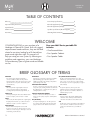
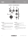
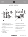
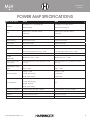
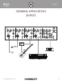
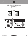
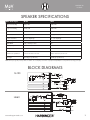
0
0
0
0
0
0
0
0
M60
60 WATT
4 CHANNEL MIXER
M120
120WATT PORTABLE PA
M60
60WATT PORTABLE PA
PORTABLE PA
SYSTEMS
PORTABLE PA
SYSTEMS
TM
TABLE OF CONTENTS
Glossary
2
Power Amp Specifications
8
Important Safety Instructions
3
General Application (Input)
9
Input Channels
5
General Application (Output)
10
Master Section
6
Speaker Specifications/Block Diagrams
11
Rear Panel
7
Warranty/FCC Statements
12
WELCOME
CONGRATULATIONS on your purchase of a
Harbinger 4-Channel PA System. Built with rugged,
carpet-covered wood enclosures, they are the ideal
choice for musicians looking for a PA that delivers
great sound night after night. This manual will
help you setup your new system. By following our
guidelines and suggestions, your new Harbinger
will provide many years of great sound and reliable
service.
Your new MüV Series portable PA
includes:
•One Powered Mixer
•Two Speaker Cabinets
•Two Speaker Cables
BRIEF GLOSSARY OF TERMS
BALANCED
A 2-conductor (plus shield), low-impedance
connection. Balanced cables are the preferred
method for hum-free interconnection of a given sound
system for their noise-rejection characteristics. (Also
see Unbalanced.)
CHANNEL
One of any number of signal paths in an audio
circuit, such as input channel, output channel,
recording channel, left channel, right channel, etc.
DECIBEL (dB)
A term representing the ratio between different audio
levels. For example, a ratio of 1000:1 = 60dB.
DELAY
Like an echo, this effect duplicates the original signal,
then plays it back at a rate you control. The rate at
which these repeats occur is the “delay time.”
EQUALIZATION
Electronic filters that adjust the level of certain
frequencies. Used for tone enhancement or to reduce
extraneous sounds. Two types of EQ shapes are Peak
and Shelving, described below.
2
IMPEDANCE
Resistance in an electrical circuit measured in Ohms
(Ω). Maintaining proper impedance (between
amplifier and speakers for example) is important to
prevent damage to the amp.
PEAK EQUALIZER CONTROL
Increase or decrease of a frequency range centered
at a specific point, resulting in an EQ curve that looks
like a hill (increase) or a valley (decrease). (Also see
Shelving Equalizer Control.)
SHELVING EQUALIZER CONTROL
Increase or decrease of all frequencies above or
below a specific point. (Compare to Peak Equalizer
Control.)
TRS (BALANCED)
Acronym for Tip-Ring-Sleeve — the three parts of a
two-conductor (plus shield) audio plug. TRS phone
plugs are often used for “balanced” connections.
TRS (UNBALANCED RES INSERT)
Another common TRS application is for “dual
unbalanced” connections, such as insert send/return
jacks or stereo Y-Cord. These are used for inserting
an external processor into a signal path. (See page 6
of this manual.)
TS
Acronym for Tip-Sleeve, the two parts of an
unbalanced, single-conductor (plus shield) phone
plug. TS connectors are sometimes called mono or
unbalanced plugs or jacks.
UNBALANCED
A single-conductor (plus shield), high-impedance
connection. Most commonly used for instrument
connections and cable runs of less than 20 feet.
XLR
The three-pin connector universally used for balanced
audio connections. A balanced connection reduces
outside noise and interference. (See Balanced
above.)
M60 and M120 Owner's Manuel
PORTABLE PA
SYSTEMS
TM
IMPORTANT SAFETY INSTRUCTIONS
Please keep this instruction manual for future reference and for the duration
of owning the MüV powered loudspeaker. Please carefully read and
understand the instructions inside this owner’s manual before attempting to
operate your new powered loudspeaker.
10. P OWER SOURCES – This product should be operated only from the
type of power source indicated on the rating label. If you are not sure
of the type of power supply to your home, consult your product dealer
or local power company.
This instruction manual includes essential safety information regarding the
use and maintenance of the amplifier. Take special care to heed all warning
symbols and signs inside this manual and those printed on the amplifier on
the back of the loudspeaker.
11. G
ROUNDING OR POLARIZATION – Do not defeat the safety purpose
of the polarization or grounding-type plug. The wide blade or the third
prong is provided for your safety. If the provided plug does not fit your
outlet, consult an electrician for replacement of the obsolete outlet. Do
not defeat the safety purpose of the 3rd pin grounding prong.
WARNING
TO PREVENT FIRE OR SHOCK HAZARD, DO NOT EXPOSE THE AMPLIFIER
TO WATER/MOISTURE, NOR SHOULD YOU OPERATE THE AMPLIFIER
NEAR ANY WATER SOURCE.
The exclamation point triangular symbol is intended to alert the user to the
presence of important operating and maintenance(servicing) instructions in
the user manual accompanying the Amplifier.
The lightning flash with an arrow triangular symbol is intended to alert
the user to the presence of non-insulated “dangerous voltage” within the
product’s enclosure, and may be of sufficient magnitude to constitute a risk
of electric shock.
WARNING
Handle the power supply cord with care.
Do not damage or deform it as it may cause electric shock or malfunction
when used. Hold the plug attachment when removing from wall outlet. Do
not pull on the power cord.
IMPORTANT SAFETY PRECAUTIONS
1. R
EAD INSTRUCTIONS – All the safety and operating instructions should
be read before this product is operated.
2. R
ETAIN INSTRUCTIONS – The safety and operating instructions should
be retained for future reference.
3. H
EED WARNINGS – All warnings on the amplifier and in the operating
instructions should be adhered to.
4. F OLLOW INSTRUCTIONS – All operating and use instructions should
be followed.
5. D
O NOT turn on the MüV amplifier module before connecting all other
external devices.
6. W
ATER AND MOISTURE – Moisture can damage the MüV amplifier
module and can cause corrosion of electrical contacts. The speaker
system should not be used near water - for example, a bathtub,
washbowl, kitchen sink, laundry tub, wet basement, or near a swimming
pool, and the like.
7. C
ARTS AND STANDS – The speaker system should be used only with
a cart or stand that is recommended by the manufacturer. A speaker
and cart combination should be moved with care. Quick stops, excessive
force, and uneven surfaces may cause the speaker and cart combination
to overturn.
8. W
ALL OR CEILING MOUNTING – The product should never be
mounted to a wall or ceiling.
9. H
EAT – The loudspeaker on the back of the MüV loudspeaker should be
situated away from heat sources such as radiators, heat registers, stoves,
or other sources (including amplifiers) that produce heat.
www.HarbingerProAudio.com
12. POWER-CORD PROTECTION – Power supply cords should be
routed so that they are not likely to be walked on or pinched by items
placed upon or against them, paying particular attention to the cord
in correspondence of plugs, convenience receptacles, and the point
where they exit from the amplifier.
13. CLEANING – The speaker and amplifier should be cleaned only as
recommended by the manufacturer. Clean by wiping with a dry cloth.
Avoid getting water inside the speaker or amplifier.
14. N
ON-USE PERIODS – The power cord of the amplifier should be
unplugged from the outlet when left unused for a long period of time.
15. OBJECT AND LIQUID ENTRY – Care should be taken so that objects do
not fall and liquids are not spilled into the enclosure through openings.
16. DAMAGE REQUIRING SERVICE – The amplifier should be serviced by
qualified service personnel when:
A. The power supply cord or the plug has been damaged; or
B. Objects have fallen, or liquid has been spilled into the amplifier; or
C. The amplifier has been exposed to rain; or
D. The amplifier does not appear to operate normally or exhibits a
marked change in performance; or
E. T he amplifier has been dropped, or the enclosure damaged.
17. Keep the speaker system out of extended or intense direct sun light.
18. N
o containers filled with any type of liquid should be placed on or near
the speaker system.
19. S
ERVICING – The user should not attempt any service to the speaker
and/or amplifier beyond that described in the operating instructions.
All other servicing should be referred to qualified service personnel.
20. V
ENTILATION – Slots and openings in the amplifier are provided
for ventilation and to ensure reliable operation of the product and to
protect it from overheating. These openings must not be blocked or
covered. The openings should never be blocked by placing the product
on a bed, sofa, rug, or other similar surface. This product should not be
placed in a built-in installation such as a bookcase or rack.
21. A
TTACHMENTS – do not use attachments not recommended by the
product manufacturer, as they may cause hazards.
22. A
CCESSORIES – Do not place this product on an unstable cart, stand,
tripod, bracket, or table. The product may fall, causing serious injury to
a child or adult, and serious damage to the product. Use only with a
cart, stand, tripod, bracket, or table recommended by the manufacturer,
or sold with the product.
3
PORTABLE PA
SYSTEMS
TM
23. L IGHTNING – For added protection during a lightning storm, or when
it is left unattended and unused for long periods of time, unplug it from
the wall outlet. This will prevent damage to the product due to lightning
and power-line surges.
24. R
EPLACEMENT PARTS – When replacement parts are required, be
sure the service technician has used replacement parts specified by
the manufacturer or have the same characteristics as the original
part. Unauthorized substitutions may result in fire, electric shock, or
other hazards.
25. S
AFETY CHECK – Upon completion of any service or repairs to
this product, ask the service technician to perform safety checks to
determine that the product is in proper operating condition.
HEARING DAMAGE AND PROLONGED EXPOSURE TO
EXCESSIVE SPLs
Harbinger MüV Series powered loudspeakers are capable of producing
extremely loud volume levels that can cause permanent hearing damage
to performers, production crews or the audience. Hearing protection is
recommended during long-term exposure to high SPLs (sound pressure
levels).
Remember, if it hurts, it is definitely too loud! Long term exposure
to high SPLs first causes temporary threshold shifts; limiting your
ability to hear the actual loudness and exercise good judgment.
Repeated long term exposure to high SPLs will cause permanent
hearing loss.
26. F USES – Always use the correct rating and type of fuse as indicated
on the rear panel of the amplifier. Note the proper rating fuse is
determined by the AC line voltage in the country this speaker system is
being operated. COMPLETELY DISCONNECT POWER CORD FROM
AMPLIFIER BEFORE ATTEMPTING TO REPLACE FUSE!
Please note the recommended exposure limits in the accompanying table. More information about these limits is available on the US government
Occupational Safety and Health (OSHA) website at: www.osha.gov
27. AC SELECT SWITCH: This switch must be set to match the AC line
voltage in the country this speaker system is being operated. To change
the setting, loosen (do not remove) the two screws left and right the
slide switch. Temporarily move the protective cover strip and slide the
actuator to match the voltage in your country. Place the protective cover
strip back over the switch and tighten the two screws. COMPLETELY
DISCONNECT POWER CORD FROM AMPLIFIER BEFORE
ATTEMPTING TO CHANGE AC VOLTAGE SETTINGS!
Permissible Noise Exposures (1)
28. H
ARBINGER MÜV SERIES POWERED LOUDSPEAKERS ARE NOT
DESIGNED FOR TEMPORARY OR PERMANENT SUSPENSION. ANY
ATTEMPT TO SUSPEND A MÜV SERIES CABINET COULD RESULT IN
INJURY OR DEATH.
To prevent electric shock, do not use a polarized plug with an extension
cord, receptacle or other outlet unless the blades can be fully inserted to
prevent blade exposure.
RISK OF
RISQUE DE CHOC
ELECTRIC SHOCK ELECTRIQUE NE
DE CHOC
DORISK
NOT OF
OPEN RISQUE
PAS OUVRIR
ELECTRIC SHOCK ELECTRIQUE NE RISK OF
DO NOT OPEN
PAS OUVRIR
ELECTRIC SHOCK
Duration per day, hours
Sound level dBA slow response
8
90
6
90
4
90
3
90
2
100
1.5
102
1
105
0.5
110
0.25 or less
115
RISQUE DE CHOC
ELECTRIQUE NE
CAUTION: To reduce the risk of electric shock,
not
DO NOTdo
OPEN
PAS OUVRIR
remove
chassis.
No user-serviceable
parts
inside.
CAUTION:
To reduce
the risk of electric
shock,
do not
Refer
servicing
qualified
service personnel.
remove
chassis.toNo
user-serviceable
inside.
CAUTION: Toparts
reduce
the risk of electric shock, do not
Refer servicing to qualified service personnel.
AVERTISEEMENT: Pour remove
réduire les
risquesNo
d’incendie
et
chassis.
user-serviceable
parts inside.
d’électrocution, ne Pour
pas exposer
ce matérial
àqualified
la pluie ou
Refer
tod’incendie
service personnel.
AVERTISEEMENT:
réduireservicing
les
risques
et
àd’électrocution,
l’humidité. ne pas exposer ce matérial à la pluie ou
AVERTISEEMENT: Pour réduire les risques d’incendie et
à l’humidité.
d’électrocution, ne pas exposer ce matérial à la pluie ou
à l’humidité.
THIS SYMBOL IS INTENDED TO ALERT THE USER TO THE PRESENCE
OF IMPORTANT OPERATING AND MAINTENANCE (SERVICING)
INSTRUCTIONS IN THE LITERATURE ACCOMPANYING THE UNIT.
APPARATUS SHALL NOT BE EXPOSED TO DRIPPING OR SPLASHING
AND THAT NO OBJECTS FILLED WITH LIQUIDS, SUCH AS VASES,
SHALL BE PLACED ON THE APPARATUS.
4
M60 and M120 Owner's Manuel
PORTABLE PA
SYSTEMS
TM
INPUT CHANNELS
1
2
3
4
6
5
1 LOW EQ
This shelving control gives 15dB of boost or cut at 80Hz and below.
Add warmth to vocals or extra punch to guitars, drums and synths
by turning to the right. Turn to the left to reduce stage rumble, hum
or a muddy sound.
2 HIGH EQ
This shelving control gives 15dB of boost or cut at 12KHz and
above. Turn to the right to boost high frequencies, adding crispness
to percussion from drum machines, cymbals and synths. Turn to the
left to cut these frequencies, reducing sibilance or hiss.
3 VOLUME
5
This level control determines the proportion of the channel
signal in the mix.
4 FX SEND
This level control sets the amount of signal that will be
sent to the built-in digital delay effect.
5 MIC & LINE INPUT
This MIC input accepts male XLR while the LINE input
accepts a 1/4’’ type phone plug. You can use only one of the two
connectors at a time.
6 PEAK LED (M120 only)
This LED indicates that the input signal is too loud, and may distort
the sound or damage the circuitry. If the PEAK LED consistently
remains lit, reduce the output volume of the source, or lower the
channel volume.
FUSE: 2A 250V
M60 and M120 Owner's Manuel
AC 120V ~50/60HZ 200W
ON
8 OHM
E: T2A 250V
60 WATTS
8 OHM
PORTABLE PA
SYSTEMS
TM
CLASS 2 WIRING
AVIS: Ne pas ouvrir l'appareil!
Danger de décharge électrique!
0/60HZ 108VA MAX
MASTER SECTION
HARBINGER
P.O. BOX 5111
THOUSAND OAKS,
CA 91359-5111
MADE IN CHINA
AC~
M120
0
–15dB
VOLUME
LOW
2
M60
1
0
+15dB
0
+15dB
HIGH
–15dB
VOLUME
3
2
0
+15dB
LOW
–15dB
+15dB
HIGH
FX MASTER
VOLUME
TIME
REPEAT
POWER
M60
60 WATT
4 CHANNEL MIXER
3
FX
FX
FX
4
4
LINE
MIC
5
LINE
MIC
7
AUX IN
LEVEL
LINE
6
5
1 MASTER EQ (M120)
LOW: This shelving control gives 15dB of boost or cut
at 80Hz and below.
MID: This is a band peak equalizer with a control range of +/-15dB
at 1KHz.
HIGH: This shelving control gives 15dB of boost or cut
at 12KHz and above.
2 FX
This controls the signal from the input channels, processed by the
built-in digital delay.
FX MASTER:This knob adjusts the mix level of the
effect sound.
TIME: Turn this knob to the right to increase the interval time
between delays, to the left to decrease.
3 POWER INDICATOR
6
When the power switch at the rear panel is turned on,
this indicator will illuminate.
6
4 AUX IN CONTROL
This knob adjusts the level from the AUX Inputs to the
Master Volume.
5 MASTER VOLUME
This knob adjusts the total output Volume. Turn Master Volume down
before turning unit on or off.
6 AUX IN & REC OUT
The AUX IN Phono Jacks allow MP3/CD players to be
connected to the amplifier. The RECORD OUTPUT RCA Phono Jacks
provide signal output to audio equipment.
The nominal output level and impedance are -10dBV/600ohms.
7 FOOTSWITCH (M120)
This jack accepts a footswitch (not included) to turn the digital
effects on or off. Compatible with momentary footswitch (normal
open circuit).
M60 and M120 Owner's Manuel
PORTABLE PA
SYSTEMS
TM
REAR PANEL
M120
1
2
4
FUSE: 2A 250V
FUSE: 2A 250V
AC 120V 50/60HZ 200W
AC 120V ~50/60HZ~200W
AVIS: Ne pas ouvrir l'appareil!
AVIS: Ne pas ouvrirDanger
l'appareil!
de décharge électrique!
Danger de décharge électrique!
3
3
2
M60
OFF
ON
OFF
ON
8 OHM
FUSE: T2A 250V
FUSE: T2A 250V
4
8 OHM
8 OHM
8 OHM
60 WATTS
60 WATTS
HARBINGER
HARBINGER
P.O. BOX 5111
CLASS 2 WIRING
P.O. BOX 5111THOUSAND OAKS,
CLASS 2 WIRING
THOUSAND OAKS,CA 91359-5111
CA 91359-5111
AVIS: Ne pas ouvrir l'appareil!
SERIAL NUMBER
SERIAL NUMBER
AVIS: Ne pas ouvrirDanger
l'appareil!
de décharge électrique!
AC 120V~50/60HZ 108VA MAX
Danger de décharge électrique!
AC 120V~50/60HZ 108VA
MAX
TM
MADE IN CHINA
MADE IN CHINA
TM
M60
M60
AC~
AC~
1 AC POWER SOCKET
4 MAIN INSERT
Accepts the removable power cable.
0
0
0
0
2 POWER SWITCH
–15dB
–15dB
+15dB –15dB
LOW
+15dB
–15dB
LOW +15dB
HIGH
0
0
+15dB
HIGH
VOLUME
0
–15dB
+15dB –15dB
–15dB
+15dB
–15dB
+15dB
VOLUME
LOW
LOW
HIGH
0
0
0
+15dB
HIGH
VOLUME
–15dB
0
+15dB
–15dB
+15dB
LOW +15dB
VOLUME
HIGH
LOW
This switches the powered mixer on and off. While on,
the blue LED indicator onFX the front panel is lit. FX
FX
FX
0
+15dB
HIGH
VOLUME
FX
–15dB
VOLUME
FX
3 SPEAKER OUTPUT JACKS
This unbalanced insert point is a break between the main out
and the built-in amplifier to allow the main output
to be sent to an
M60
M60 60
WATT
TIME
REPEAT POWER
LOW
HIGH
VOLUME MASTERFX MASTER
60 WATT
TIME
REPEAT POWER
LOW
HIGH
VOLUME
4 CHANNEL MIXER
external
signal FXprocessor.
The insert
is a 1/4’’
4 CHANNELTRS
MIXER phone jack
which is normally bypassed. When a jack, such as the one below,
FX
is inserted,
theFX signal path is broken.
The main output signal appears on the TIP of the plug and the
AUX IN
IN
LEVEL on the RING. An unbalanced 1/4” insert
external
signal
isAUXreturned
MIC
LINE LEVEL
MIC
LINE
cable is required to connect to equipment with separate send and
return jacks as shown below:
0
Connect bothMICspeakers to
these jacks.
The minimum
MIC
LINE
MIC
LINE
MIC
LINE
MIC
LINE
MIC
LINE
impedance load is 4Ω. Do not connect more than two 8Ω speakers
or damage may occur.
LINE
0
0
–15dB
+15dB –15dB
+15dB –15dB
+15dB
0
+15dB
SIGNAL OUT
INSERT
(not included)
7
SIGNAL RETURN
M60 and M120 Owner's Manuel
PORTABLE PA
SYSTEMS
TM
POWER AMP SPECIFICATIONS
MüV Series Specs
M120
M60
Max Output Power 120 Watts (@ 4Ω)
Max Output Power (watts): 8Ω–45
88 Watts (@ 8Ω)
Minimum 4Ω load: 4Ω–60
Balanced mono: 4 Mic/line channels
Balanced mono: 4 Mic/line channels
2 Aux Inputs
2 Aux Inputs
Line Output
Record Out: RCA Pair
Record Out: RCA Pair
Channel Strips (4)
Volume Controls: Rotary
Volume Controls: Rotary
Master Section
Rotary Fader: Master
Rotary Fader: Master
Built-in Digital Effect
Digital Delay: (2–150ms)
Digital Delay: (2–150ms)
Master output (all faders down): –86dBu
Master output (all faders down): –86dBu
Power amp output (all faders down): –55dBu
Power amp output, all faders down: –55dBu
THD
@120 watts: 4Ω <1%
@60 watts: 4Ω <1%
Crosstalk
(1KHz@ 0dBu)
Channel fader down < –63dB
Channel fader down < –63dB
Frequency Response (Mic
input to output)
20Hz to 20kHz line level output @+4dBu into 600Ω
+1/–3dB
20Hz to 20kHz line level o/p @+4dBu into 600Ω
+1/–3dB
Sensitivity @ mixer output
+4dBu
1Mic/Line: –50dBu/–35dBu
Mic/Line: –50dBu
Tape in: –6dBu
Tape in: –6dBu
2 band +/–15dB
2 band +/–15dB
Low EQ: 80Hz Shelving
Low EQ: 80Hz
Hi EQ: 12kHz Shelving
Hi EQ: 12kHz
Power Amp
Inputs
Noise
Channel Equalization
3 band +/–15dB
Master Equalization
Low EQ: 80Hz Shelving
Mid EQ: 1kHz Peak
NA
Hi EQ: 12kHz Shelving
Microphone Preamp E.I.N.
(150Ω terminated, max gain) –122dBm
(150Ω terminated, max gain) –122dBm
Power Requirements
AC120V ~ 50–60Hz
AC120V ~ 50–60Hz
Dimensions
H 8.85” x W 18.9” x D 5.9”
18.31”x 6.10”x 8.27”
Weight
19 lbs.
16.31 lbs.
www.HarbingerProAudio.com
8
PORTABLE PA
SYSTEMS
TM
GENERAL APPLICATION
(INPUT)
www.HarbingerProAudio.com
9
PORTABLE PA
SYSTEMS
TM
GENERAL APPLICATION
(OUTPUT)
CAUTION: Minimum 4Ω load. Use a maximum of two 8Ω speakers.
www.HarbingerProAudio.com
10
PORTABLE PA
SYSTEMS
TM
SPEAKER SPECIFICATIONS
MüV Series Specs
M120
M60
RMS power handling
80W / 8Ω
50W / 8Ω
Peak power handling
110W / 8Ω
80W / 8Ω
Impedance load
8Ω
8Ω
Horn construction
Compression Driver
Piezo (piezoelectric)
Woofer construction:
12” cone diaphragm
10” cone diaphragm
Magnet weight
30 oz
20 oz
CROSSOVER
3.8K / -12dB per octave
NA
Frequency response
40Hz–20kHz
40HZ–20kHz
Max SPL
116dB
114dB
Dimensions of speaker box
H 23.2” x W 14.4” x D 12.8”
H18.7” x W 12.7”/9” x D 11.2”
Net weight
25.5 lbs (per speaker box)
16.6 lb (per speaker box)
NOTE: The max power (peak) of each speaker box is 80W in order to satisfy the powered mixer’s output (max in 80W/8Ω)and to avoid speaker burnout during peak output.
BLOCK DIAGRAMS
M120
HA60
www.HarbingerProAudio.com
11
PORTABLE PA
SYSTEMS
TM
WARRANTY
Have a question about service, warranty or parts?
Call 888-286-1809 (Toll Free)
So we may serve you better, please register on-line at www.HarbingerProAudio.com
2 YEAR HARBINGER LIMITED WARRANTY
For warranty support, please visit our website at
www.HarbingerProAudio.com, or contact our Support Team at
888-286-1809 for assistance. Harbinger will repair or replace the unit
at Harbinger’s discretion.
warranty and the implied warranties of merchantability and fitness for a
particular purpose are limited to the two (2) year warranty period. Some
states do not allow limitation on how long an implied warranty lasts, so the
above limitation may not apply to you. There are no express warranties
beyond those stated here. In the event that applicable law does not allow
the limitation of the duration of the implied warranties to the warranty
period, then the duration of the implied warranties shall be limited to as
long as is provided by applicable law. No warranties apply after
that period.
This warranty does not cover service or parts to repair damage caused
by neglect, abuse, normal wear and tear and cosmetic appearance to the
cabinetry not directly attributed to defects in materials or workmanship.
Also excluded from coverage are damages caused directly or indirectly
due to any service, repair(s), or modifications of the cabinet, which has not
been authorized or approved by Harbinger. This two (2) year warranty
does not cover service or parts to repair damage caused by accident,
disaster, misuse, abuse, burnt voice-coils, over-powering, negligence,
inadequate packing or inadequate shipping procedures.
Retailer and manufacturer shall not be liable for damages based upon
inconvenience, loss of use of product, loss of time, interrupted operation
or commercial loss or any other incidental or consequential damages
including but not limited to lost profits, downtime, goodwill, damage to
or replacement of equipment and property, and any costs of recovering,
reprogramming, or reproducing any program or data stored in equipment
that is used with Harbinger products. This guarantee gives you specific
legal rights; you may have other legal rights, which vary from state to
state.
The sole and exclusive remedy of the foregoing limited warranty shall be
limited to the repair or replacement of any defective or non-conforming
component. All warranties including, but not limited to, the express
Harbinger P.O. Box 5111, Thousand Oaks, CA 91359-5111
Harbinger provides, to the original purchaser, a two (2) year limited
warranty on materials and workmanship on all Harbinger cabinets,
loudspeaker and amplifier components from the date of purchase.
All trademarks and registered trademarks mentioned herein are
recognized as the property of their respective holders.
FCC STATEMENTS
1. Caution: Changes or modifications to this unit not expressly approved by the
party responsible for compliance could void the user’s authority to operate the
equipment.
2. Note: This equipment has been tested and found to comply with the limits for
a Class B digital device, pursuant to Part 15 of the FCC Rules. These limits are
designed to provide reasonable protection against harmful interference in a
residential installation. This equipment generate, uses, and can radiate radio
frequency energy and , in not installed and used in accordance with the instructions,
may cause harmful interference to radio communications. However, there is
no guarantee that interference will not occur in a particular installation. If this
12
equipment does cause harmful interference to radio or television reception, which
can be determined by turning the equipment off and on, the user is encouraged to
try to correct the interference by one or more of the following measures:
• Reorient or relocate the receiving antenna
• Increase the separation between the equipment and receiver
• Connect the equipment into an outlet on a circuit different from that to which
the receiver is connected
• Consult the dealer or an experienced radio/TV technician for help
M60 and M120 Owner's Manuel