1
3URGXFW1R
9HUVLRQ$
PLQL$3,
Service Manual
ELR0pULHX[VD 69280 Marcy-l’Etoile / France
Tel. 04 78 87 20 00 - Fax 04 78 87 20 90 Telex 330967
297.249
Printed in France / RCS / Lyon B 673 620 399
V.J 12.96
Australia
ELR0pULHX[9LWHN$XVWUDOLD3W\/WG
Unit 1, 6 Gladstone Road
Castle Hill NSW 2154
tel. (61) 2.899 4600 - fax (61) 2.899 1232
Austria
ELR0pULHX[$XVWULD*PE+
Eduard-Kittenberger-Gasse 97
A-1230 Wien
tel. (43) 1.86 50 650 - fax (43) 1.86 50 661
Belgium
ELR0pULHX[%HQHOX[VDQY
rue Victor Hugo 215 - 1030 Bruxelles
tel. (32) 2.743 01 70 - fax (32) 2.733 55 97
Korea
ELR0pULHX[.RUHD&R/WG
6th floor Duk Soo Building
234-9 Nonhyun-dong, Kangnam-ku - Séoul
tel. (82) 2.547 6262 - fax (82) 2.547 6263
Mexico
ELR0pULHX[0p[LFR6$GH&9
Chihuahua 88, Col. Progreso
México 01080, D.F.
tel. (52) 5.550 2232 / 550 7129 - fax (52) 5.550 4543
The Netherlands
ELR0pULHX[%HQHOX[%9
Bruistensingel 620
5232 AJ 's - Hertogenbosch
tel. (31) 73.6441818 - fax (31) 73.6442211
Brazil
%LRODE0pULHX[6$
Estrada Mapuá
491 Jacarepguá
CEP 22710 261 Rio de Janeiro R.J
tel. (55) 21.445 5454 - fax (55) 21.445 6099
Canada
ELR0pULHX[&DQDGD,QF
4535, Rue Dobrin
St Laurent - Québec H4R 2L8
tel. (1) 514.336 7321 - fax (1) 514.336 6450
Chile
ELR0pULHX[&KLOH6$
Av. Providencia 1945
Oficina 603 - Santiago Chile
tel. (56) 2.334 29 33/334 15 93 - fax (56) 2.233 81 51
France
ELR0pULHX[VD
69280 Marcy-l'Etoile
tel. (33) 04 78 87 20 00 - fax (33) 04 78 87 20 90
Germany
ELR0pULHX['HXWVFKODQG*PE+
Weberstrasse 8 - D 72622 Nürtingen
tel. (49) 7022.3007.0 - fax (49) 7022.36110
Hong Kong - China
ELR0pULHX[9LWHN+RQJ.RQJ/WG
Unit 1701-2, 17/F, Nanyang Plaza
No. 57 Hung To Toad, Kwun Tong
Kowloon - Hong Kong
tel. (852) 2356 7033 - fax (852) 2330 2085
Poland
ELR0pULHX[3ROVND6S]RR
ul. Zeromskiego 17
01-882 Warszawa
tel. (48) 22.663 44 44 - fax (48) 22.669 99 42
Portugal
ELR0pULHX[3RUWXJXHVD/GD
Calçada de Santa Catarina, N° 9 C
1495 Cruz Quebrada
tel. (351) 1.4 15 02 78 - fax (351) 1.4 15 01 18
Russia
RRRELR0pULHX[
Mescheriakova 4
123362 Moscow
tel. & fax (7) 095.955 18 34
Spain
ELR0pULHX[(VSDxDVD
Manuel Tovar 36 - 28034 Madrid
tel. (34) 91.358 11 42 - fax (34) 91.358 06 29
Switzerland
ELR0pULHX[6XLVVHVD
51, avenue Blanc - 1202 Genève
tel. (41) 22.906 57 60- fax (41) 22.906 57 42
United Kingdom
ELR0pULHX[8./LPLWHG
Grafton Way, Basingstoke
Hampshire RG22 6HY
tel. (44) 1256.461881 - fax (44) 1256.816863
USA
Italy
ELR0pULHX[,WDOLD6S$
Via G. Moscati 9 - 00168 Roma
tel. (39) 6.3014454 - fax (39) 6.3050079
ELR0pULHX[9LWHN,QF
595 Anglum Drive - Hazelwood
Missouri 63042 - 2395
tel. (1) 314.731 8500 - fax (1) 314.731 8700
Japan
ELR0pULHX[9LWHN-DSDQ/WG
Otsuka HT Bldg.
43-1, Minami-Otsuka 3-chome
Toshima-ku, Tokyo 170
tel. (81) 3.5952 0821 - fax (81) 3.5952 083
Distribution in over 130 countries
This document will be updated on each Software modification or any other change.
Information supplied in this document is liable to modification before the products described
become available.
This document may contain information or references concerning certain bioMérieux products,
programs and services not planned for your country, but this does not mean that bioMérieux intends
to commercialize them.
To obtain copies of publications or for any technical requests, contact your bioMérieux Engineer or
your local bioMérieux distributor.
/LDELOLW\GLVFODLPHU
bioMérieux SA will concede no formal or implicit warranty, as regards this Manual, its quality,
performance or appropriate use in any type of specific application.
This Manual can be modified by bioMérieux SA without notice, and represents no commitment or
liability whatsoever from bioMérieux SA.
&23<5,*+7%,20(5,(8;6$
bioMérieux SA does in no case concede users of this Manual any right for reproduction, adaptation
or translation, by any process and in any country.
As the Law of March 11th, 1957 authorizes first "copies or reproductions strictly reserved for the
private use of the copists and not intended for collective use" and second, analyses or short
quotings intended for examples or illustrations, "any representation or reproduction, whether
integral or partial made without the author's or owners' consent is illegal". (Articles 40 and 41, Law
of March 11th, 1957).
Such representation or reproduction, by any process whatsoever, would therefore be considered as
a fraudulent imitation penalized by articles 425 et seq of the French Penal Code.
7$%/(2)&217(176
&+$37(5+2:7286(7+,60$18$/
INTRODUCTION.......................................................................................................................... 1-3
SCOPE OF THE MANUAL........................................................................................................... 1-4
FINDING TOPICS AND PROCEDURES ..................................................................................... 1-5
HOW THE MANUAL IS ORGANISED ......................................................................................... 1-6
&+$37(5)81&7,21$/'(6&5,37,21
INTRODUCTION.......................................................................................................................... 2-3
PRESENTATION ......................................................................................................................... 2-4
INTRODUCTION TO IDENTIFICATION AND SUSCEPTIBILITY TESTING .............................. 2-5
DESCRIPTION/AIM ..................................................................................................................... 2-6
GENERAL DESCRIPTION........................................................................................................... 2-7
Configuration Components.................................................................................................... 2-7
Hardware..................................................................................................................... 2-7
Software ...................................................................................................................... 2-7
Consumables .............................................................................................................. 2-7
PRINCIPLE OF OPERATION ...................................................................................................... 2-9
Functions ............................................................................................................................... 2-9
Presentation........................................................................................................................... 2-9
Characteristics ....................................................................................................................... 2-9
GENERAL CHARACTERISTICS ............................................................................................... 2-11
Environmental Conditions.................................................................................................... 2-11
Physical Features ................................................................................................................ 2-11
Electrical Characteristics ..................................................................................................... 2-12
Characteristics of Optical Components ............................................................................... 2-12
Computer ............................................................................................................................. 2-13
Central Processing Unit....................................................................................................... 2-13
Software............................................................................................................................... 2-13
Consumables....................................................................................................................... 2-13
&+$37(535(/,0,1$5<,16758&7,216
INTRODUCTION.......................................................................................................................... 3-3
RECOMMENDATIONS FOR INSTALLATION AND USE............................................................ 3-4
UNPACKING 0,1,$3,................................................................................................................. 3-4
ASSEMBLY AND INSTALLATION............................................................................................... 3-5
Choosing a Location .............................................................................................................. 3-5
Setting Up the Strip Tray ....................................................................................................... 3-7
Connections........................................................................................................................... 3-7
Preparing for Operation ......................................................................................................... 3-7
Adjusting the Height of PLQL$3, ............................................................................................ 3-7
mini API Service Manual V.J 12.96
V-1
&+$37(5'(6&5,37,212)02'8/(6
INTRODUCTION ......................................................................................................................... 4-3
OVERVIEW.................................................................................................................................. 4-5
0,1,$3, ..................................................................................................................................... 4-12
POWER SUPPLY BLOCK ......................................................................................................... 4-24
OPTICAL BLOCK....................................................................................................................... 4-38
MANAGEMENT BLOCK ............................................................................................................ 4-60
BORD INTERFACE SERIAL LCD CPU..................................................................................... 4-84
COMPUTER BLOCK ................................................................................................................. 4-92
PRINTER BLOCK .................................................................................................................... 4-116
&+$37(535(9(17,9(0$,17(1$1&(
INTRODUCTION ......................................................................................................................... 5-3
TESTING 0,1,$3, ...................................................................................................................... 5-4
PREVENTIVE MAINTENANCE ................................................................................................... 5-5
Cleaning PLQL$3, .................................................................................................................. 5-5
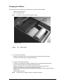
Changing the Ribbon........................................................................................................... 5-11
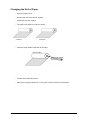
Changing the Roll of Paper ................................................................................................. 5-12
Changing the Fuse .............................................................................................................. 5-14
FIELD ENGINEER PREVENTIVE MAINTENANCE .................................................................. 5-15
Reader Module .................................................................................................................... 5-15
&+$37(57528%/(6+227,1**8,'(
INTRODUCTION ......................................................................................................................... 6-3
OVERVIEW.................................................................................................................................. 6-4
Determining the Problem....................................................................................................... 6-4
Solving the Problem .............................................................................................................. 6-4
ERROR MESSAGE TROUBLESHOOTING ................................................................................ 6-5
Error Messages Appearing in the PLQL$3, Software ............................................................ 6-5
Reference alarm .................................................................................................................... 6-6
REPAIR BY UNIT REPLACEMENT............................................................................................. 6-8
Introduction............................................................................................................................ 6-8
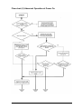
Flow chart (1) Abnormal Operation at Power On .................................................................. 6-9
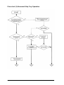
Flow chart (2) Abnormal Strip Tray Operation..................................................................... 6-10
Flow chart (3) Incorrect Data Sent to the Computer............................................................ 6-11
&+$37(535(9,286,167580(179(56,217$%/(
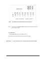
PREVIOUS INSTRUMENT VERSION TABLE ............................................................................ 7-3
Management of Versions ...................................................................................................... 7-3
Instrument Version Numbers ...................................................................................... 7-3
EPROM Version Numbers .......................................................................................... 7-4
V-2
mini API Service Manual V.J 12.96
&+$37(502'8/(63$5(3$576
INTRODUCTION.......................................................................................................................... 8-3
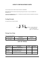
HOW TO OBTAIN SPARE PARTS .............................................................................................. 8-4
Coding Principle..................................................................................................................... 8-4
Placing Your Order ................................................................................................................ 8-4
LIST OF TOOLS .......................................................................................................................... 8-4
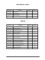
ELECTRONIC BOARD ................................................................................................................ 8-5
ELECTRICAL PARTS .................................................................................................................. 8-6
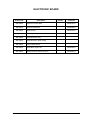
MECHANICAL PARTS................................................................................................................. 8-7
CABLES ....................................................................................................................................... 8-7
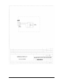
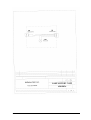
&+$37(5',$*5$06
INTRODUCTION.......................................................................................................................... 9-3
&+$37(5$33(1',;0$,17(1$1&(62)7:$5(
INTRODUCTION........................................................................................................................ 10-5
GETTING STARTED ................................................................................................................. 10-6
OVERVIEW ................................................................................................................................ 10-7
Selecting a Menu ................................................................................................................. 10-7
Selecting a Command ......................................................................................................... 10-7
Menu System Commands ................................................................................................... 10-9
New ATB 1525 Maintenance Software (ATB 1525 N)......................................................... 10-9
$7% Maintenance Software...................................................................................... 10-18
&+$37(5*/266$5<
&+$37(5,1'(;
mini API Service Manual V.J 12.96
V-3
/,672)),*85(6
)LJXUH
7LWOH
2-1
Using PLQL$3,
2-5
2-2
Reading Principle of the Test Strip Reader
2-7
2-3
Reading Principle of the Test Strip Reader
2-8
2-4
Configuration Components
3-1
Settinf up the Strip Tray
3-6
3-2
Connections
3-6
4-1
Cable Connection
4-16
4-2
Calculation of Numerical Values
4-17
4-3
Transmission graph
4-18
4-4
Reading Principle
4-19
4-5
Analogue-Digital Converter
4-20
4-6
Position of Casting Screws
4-21
4-7
Power Supply Cable Connections
4-28
4-8
Removing the Power Supply Block
4-29
4-9
Removing the Board Power
4-30
4-10
Power Supply Circuit Block Diagram
4-31
4-11
Filter Motor Drive circuit
4-33
4-12
Tray Motor Drive circuit
4-34
4-13
Switching Power Supply Card Testing and Adjustement
4-35
4-14
Board Power
4-36
4-15
Direction of the Tray DT = 200ms (tray speed)
4-37
4-16
Optical Block Cable Connections
4-42
4-17
Removing the Optical Block
4-43
4-18
Removing the Condenser
4-44
4-19
Removing the Lamp
4-45
4-20
Handling the Lamp
4-46
4-21
Removing the Board Optic Acquisition
4-47
4-22
Removing the Board Detection Tray
4-48
4-23
Removing the Board Detection Filter Holder
4-49
4-24
Lamp Control Drive Circuit
4-50
4-25
Analogical Switching
4-51
4-26
Board Detection Tray Circuit
4-52
4-27
Board Detection Filter Holder Circuit
4-52
4-28
Beam Alignment
4-53
4-29
Strip Code Reading
4-55
V-4
3DJH
2-10
mini API Service Manual V.J 12.96
4-30
Oscillogram and Holes on the Tray
4-55
4-31
Position of the Beams
4-57
4-32
Alignement of the Board Detection Tray
4-59
4-33
Managemnt Block Cable Connections
4-64
4-34
Removing the Board COM GEST2
4-65
4-35
Management Block Diagram
4-67
4-36
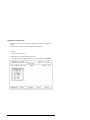
Maintenance Software Window (reference Option)
4-75
4-37
Maintenance Software Window (Reading Option)
4-76
4-38
Maintenance Software Window (Offset Option)
4-77
4-39
Maintenance Software Window (Reference Option)
4-77
4-40
Maintenance Software Window (Reading Option)
4-78
4-41
Lateral Balancing of Left and Right Channels
4-79
4-42
Board COM GEST2 Test and Adjustments points
4-79
4-43
Removing the Board Interface
4-87
4-44
Board Interface Serial LCD CUP Cable Connections
4-89
4-45
Computer Cable Connections
4-95
4-46
Removing the Board CPU PCM 4860
4-97
4-47
PCM-4860 Jumpers
4-101
4-48
PCM-4860 Connectors
4-103
4-49
Display
4-111
4-50
Display Cable Connections
4-113
4-51
Printer
4-119
4-52
Power Supply Connector
4-125
4-53
DIP Switch setting
4-127
4-54
Printer Cable Connections
4-129
4-55
Printer Interface Circuit
4-130
5-1
Strip Tray
5-6
5-2
Preparing the Photodiode Cleaning Tool
5-8
5-3
Cleaning the Photodiodes
5-8
5-4
Changing the Ribbon and the Roll of Paper
5-10
5-5
Printer Cover
5-10
5-6
Paper Cutter
5-11
5-7
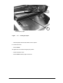
Loading the paper
5-13
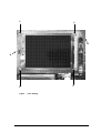
5-8
Back Panel of PLQL$3,
5-14
6-1
Back Panel of PLQL$3,
6-7
10-1
Menu Screen
mini API Service Manual V.J 12.96
10-7
V-5
V-6
mini API Service Manual V.J 12.96
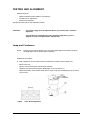
&+$37(5
+2:7286(7+,60$18$/
,1752'8&7,21
This chapter explains how to use the mini API Service Manual.
It is structured as follows:
Page
SCOPE OF THE MANUAL
1-4
FINDING TOPICS AND PROCEDURES
1-5
HOW THE MANUAL IS ORGANISED
1-6
mini API Service Manual V.J 12.96
1-3
6&23(2)7+(0$18$/
The mini API Service manual is designed to enable the Field Service Engineers involved in
maintenance tasks to accurately diagnose problems in order to repair mini API.
This chapter explains how the manual is organised and how it should be used.
The Table of Contents lists all the chapters the manual deals with. Each chapter is subdivided into
sections corresponding to a procedure or a precise description.
The reply to a question can readily be found by referring to the Table of Contents or the Index at the
end of the manual.
1-4
mini API Service Manual V.J 12.96
),1',1*723,&6$1'352&('85(6
The mini API Service manual is divided into 12 chapters to help you find what you are looking for.
7DEOHRI&RQWHQWV
The main Table of Contents of the manual is located on pages V-1 to V-4. It lists each
chapter and the procedures or topics they contain.
/LVWRI)LJXUHV
PagesV-5 to V-6contain a list of the figures of the manual.
&KDSWHU&RQWHQWV
Each chapter starts with a specific table of contents. Each table of contents shows the page
from which the different sub-chapters start, on the right of the page.
3DJH)RRWHUV
Each page of the manual has a page footer.
The footers contain the version of the manual and the page number.
,QGH[
A standard topical index is located at the back of the manual in Chapter 12. It is used to
locate a particular description or procedure.
mini API Service Manual V.J 12.96
1-5
+2:7+(0$18$/,625*$1,6('
This manual is designed to provide you with step-by-step procedures for proper maintenance of
your mini API.
Use this Service Manual when you want background or more detailed information on the mini API
components.
This chapter explains how the Service Manual is organized and how it should be used.
)XQFWLRQDO'HVFULSWLRQ
Chapter 2 gives an overview of the mini API.
− Instrument functions
− Instrument operating principle
− Characteristics and specifications
3UHOLPLQDU\,QVWUXFWLRQV
Chapter describes the installation procedure and the procedure for preliminary controls.
'HVFULSWLRQRIWKH0RGXOHV
Chapter gives for each module:
−
−
−
−
−
−
Its function.
The position on the instrument.
A block diagram.
Diagrams and technical drawings.
Procedures allowing you to assemble/disassemble the module.
Procedures to maintain and repair the instruments.
0DLQWHQDQFH
Chapter 5 describes the customer’s schedule for maintenance as well as the ATI
maintenance.
*HQHUDO7URXEOHVKRRWLQJ*XLGH
Chapter 6 describes all possible failures and gives the decision tree.
1-6
mini API Service Manual V.J 12.96
7DEOHRI3UHYLRXV,QVWUXPHQW9HUVLRQV
Chapter 7 gives you the list of different versions in the form of a table. It shows the changes
and improvements made, as well as the new instrument serial numbers for each change.
6SDUH3DUWVDQG7RROV
Chapter 8 gives the list of specific tools required to perform the adjustments and carry out
repairs on the instruments.
It also gives you the list of spare parts.
'LDJUDPV
Chapter 9 gives you the block diagrams for the mini API cards.
6RIWZDUH0DLQWHQDQFH6SHFLILFDWLRQV
Chapter 10 contains the description of the software maintenance used for the reader.
*ORVVDU\
Chapter 11 contains an alphabetical list of terms used in this manual and their definitions.
,QGH[
A standard topical index is located at the back of the manual in Chapter 12.
mini API Service Manual V.J 12.96
1-7
1-8
mini API Service Manual V.J 12.96
&+$37(5
)81&7,21$/'(6&5,37,21
,1752'8&7,21
The following topics are presented in this chapter:
Page
PRESENTATION
2-4
INTRODUCTION TO IDENTIFICATION AND SUSCEPTIBILITY TESTING
2-5
DESCRIPTION/AIM
2-6
GENERAL DESCRIPTION
2-7
• Configuration Components
− Hardware
− Software
− Consumables
PRINCIPLE OF OPERATION
2-7
2-7
2-7
2-7
2-9
• Functions
2-9
• Presentation
2-9
• Characteristics
2-9
GENERAL CHARACTERISTICS
2-11
• Environmental Conditions
2-11
• Physical Features
2-11
• Electrical Characteristics
2-12
• Characteristics of Optical Components
2-12
• Computer
2-13
• Central Processing Unit
2-13
• Software
2-13
• Consumables
2-13
mini API Service Manual V.J 12.96
2-3
35(6(17$7,21
mini API is an automatic system for bacterial identification and susceptibility testing. It can be
divided into four categories of elements:
★ hardware
★ software
★ consumables
★ user’s manual
2-4
mini API Service Manual V.J 12.96
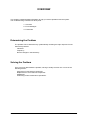
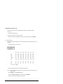
,1752'8&7,2172,'(17,),&$7,21$1'
686&(37,%,/,7<7(67,1*
−
−
Isolation
isolation medium.
orientation tests.
Standardisation of the
inoculum using the
DENSIMAT
Choice of strips
Automated technique
Manual technique
Standardised inoculation
using the electronic
pipette.
ID 32 or rapid ID 32 strips.
ATB or rapid ATB strips.
Visual reading.
Entry of biochemical profiles via the
keyboard.
Automatic Inerpretation
Automatic reading and
interpretation
)LJXUH
8VLQJPLQL$3,
mini API Service Manual V.J 12.96
2-5
'(6&5,37,21$,0
PLQL$3,is designed for the automatic identification and susceptibility testing of ,', UDSLG,',
$7%and UDSLG$7% strips.
It also enables computer assisted interpretation of API strips read visually.
2-6
mini API Service Manual V.J 12.96
*(1(5$/'(6&5,37,21
&RQILJXUDWLRQ&RPSRQHQWV
PLQL$3, is an automated instrument for identification and susceptibility testing. It consists of:
− hardware,
− software,
− consumables.
+DUGZDUH
The package includes:
★ mini API, a self-contained analytical module enabling:
− reading of test strips,
− management of results and data,
− printing of results obtained.
★ a DENSIMAT densitometer to standardise the turbidimetry of the bacterial suspension
(please refer to the manual supplied with the densitometer).
★ an electronic pipette to dispense the required amount of bacterial suspension into each
cupule of the identification and susceptibility test strips (55 µl or 135 µl) (please refer to the
manual supplied with the pipette).
6RIWZDUH
The PLQL$3,software enables:
−
−
−
−
−
−
−
interpretation of data,
interpretation of strip results (identification or susceptibility tests),
expert analysis of susceptibility tests,
storage of results on the hard disk,
printing of results,
extraction of data,
connection with a central computer.
&RQVXPDEOHV
The PLQL$3, consumables include:
− strips with associated media and reagents (see package inserts),
− ribbons and paper for the printer,
− pipette tips.
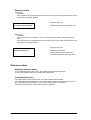
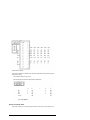
)LJXUH
5HDGLQJ3ULQFLSOHRIWKH7HVW6WULS5HDGHU
mini API Service Manual V.J 12.96
2-7
transmission %
Wavelenght
in mm
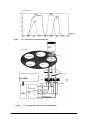
)LJXUH
'HVFULSWLRQRIWKH6SHFWUDO=RQH
Light
source
Filter support
Empty
Lens
DT Green
K60
DT Blue
K40
Diaphragm
3&$5'
ATB
Strip
Tray
Amplifier
Photodiode
Multiplexer
$'
Strip code
Scattered light
Transmitted light
)LJXUH
2-8
5HDGLQJ3ULQFLSOHRIWKH7HVW6WULS5HDGHU
mini API Service Manual V.J 12.96
35,1&,3/(2)23(5$7,21
)XQFWLRQV
− Strip identification by strip decoding.
− Two types of readings:
− turbinephelometric
− colorimetric.
− Communication with the computer.
3UHVHQWDWLRQ
− Black strip carriage.
− Blue protection rail.
&KDUDFWHULVWLFV
− Description of the spectral zone.
− Reading principle of the test strip reader :
★ 7XUELQHSKHORPHWULFUHDGLQJ
Turbinephelometric reading is used for test strips containing assimilation tests:
∗ e.g. ID 32 GN, ID 32 C, ATB UR.
A turbinephelometric reading cycle occurs in two stages:
1) Entry of the strip carriage.
Detection of the strip code.
2) Measurement without a filter.
Exit of the strip carriage.
At the end of the cycle, the result is transmitted to the computer.
★ &RORULPHWULFUHDGLQJ
Colorimetric reading is used for strips containing chromogenic substrates:
∗ e.g. ID 32 STAPH, rapid ID 32 A, rapid ID 32 E
A colorimetric reading cycle occurs in 4 stages:
1) 1st entry of the strip carriage:
Detection of the strip code,
Measurement under a K60 filter.
2) 1st exit of the strip carriage:
Measurement under a K40 filter.
3) 2nd entry of the strip carriage:
Measurement under a DT blue filter.
4) 2nd exit of the strip carriage:
Measurement under a DT green filter.
At the end of the reading cycle, the result is transmitted to the computer.
mini API Service Manual V.J 12.96
2-9
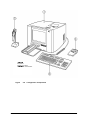
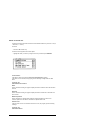
1-PLQL$3,
2-Keyboard
3-Electronic Pipette
4-'(16,0$7 Densitometer
)LJXUH
2-10
&RQILJXUDWLRQ&RPSRQHQWV
mini API Service Manual V.J 12.96
*(1(5$/&+$5$&7(5,67,&6
(QYLURQPHQWDO&RQGLWLRQV
2SHUDWLQJ7HPSHUDWXUH
+ 15° C to + 30° C (59° F to 86° F).
5HODWLYH+XPLGLW\
10 to 70%, without condensation.
0D[LPXPDOWLWXGHIRULQVWDOODWLRQ
3000 m
7\SHRILQVWDOODWLRQ
Indoor, light industrial.
'HJUHHRI3ROOXWLRQ
No. 2
Safety regulations are respected under environmental conditions defined in paragraph 1.4 of
the IEC 1010.1: 1990 and amendment 1: 1992.
3K\VLFDO)HDWXUHV
,QVWUXPHQWSDNHG
,QVWUXPHQWDORQH
Height:
50 cm (19.7 inches)
34.5 cm (13.6 inches)
Width:
60 cm (23.6 inches)
43 cm (17 inches)
Depht:
65 cm (25.6 inches)
- Protection rail in 46 cm
(18.1 inches)
'LPHQVLRQV
- Protection rail in 63cm
(24.8 inches)
0DVV
mini API Service Manual V.J 12.96
,QVWUXPHQWSDNHG
Instrument alone
32 kg (70.41 lb)
25 kg (55.11 lbs)
2-11
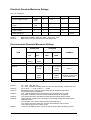
(OHFWULFDO&KDUDFWHULVWLFV
Class I Equipment
3RZHU6XSSO\
100 - 240 VAC
The power supply is self-switching.
&RQVXPSWLRQ
Maximum 2 A from 90 to 120 V AC
Maximum 1.1 A from 220 to 240 VAC
)UHTXHQF\
50 - 60 Hz
3RZHU
Maximum 240 VA
6DIHW\IXVH
External (power input block)
3.15 AT - 250 VAC
&KDUDFWHULVWLFVRI2SWLFDO&RPSRQHQWV
Light source: Halogen 12 V 20 W
− Central photosensor:
− Side photosensor:
− Strip decoding:
2-12
BP W21
SD 5421
BP W34
mini API Service Manual V.J 12.96
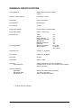
&RPSXWHU
The purpose of the computer is to control the reader and interpret data by means of the software.
It is connected to the reader to ensure automatic analysis of the strips. It is equipped with
peripherals for printing and archiving the files.
3UHVHQWDWLRQ
−
−
−
−
−
−
a Central Processing Unit,
an external Keyboard,
a Monitor,
a Floppy Disk,
an integrated Printer,
a parallel Port/serial Port.
&HQWUDO3URFHVVLQJ8QLW
&KDUDFWHULVWLFV
−
−
−
−
CPU board:
CPU:
Floppy disk:
Hard disk:
PCM 4860,
ST486 DX2 66 Mhz,
SMD 1340 EPSON 1.44 Mb,
M2614 TAU FUJITSU 1 Gb.
6RIWZDUH
A specific application developed under Turbopascal. Its main functions are:
−
−
−
−
−
−
−
communication with the reader,
interpretation of results sent by the reader,
interpretation of strip results
storage of results,
printing of results,
bidirectional interface with a central computer,
management of patient files.
&RQVXPDEOHV
6WULSV
,GHQWLILFDWLRQVWULSV
∗ conventional identification with 18 to 24 hour incubation for:
−
−
−
Gram negative rods
staphyloccci
yeasts
∗ rapid identification with 4 hour incubation at 37°C for:
−
−
−
enterobacteria
anaerobes
streptococci
mini API Service Manual V.J 12.96
2-13
6XVFHSWLELOLW\WHVWVWULSV
∗ conventional susceptibility tests with two breakpoints and 18 to 24 hour incubation are
possible for most organisms of clinical significance.
∗ UDSLG$7%susceptibility tests with one breakpoint and 4-hour incubation are possible for
enterobacteria and staphylococci.
5LEERQDQGSDSHUIRUWKH3ULQWHU
2-14
bioMérieux Paper:
Product no. 99 720
bioMérieux Ink Ribbon:
Product no. 99 721
mini API Service Manual V.J 12.96
&+$37(5
35(/,0,1$5<,16758&7,216
,1752'8&7,21
This chapter covers the very first steps you need to take before you can use PLQL$3,.
Procedures found in this chapter are:
Page
RECOMMENDATIONS FOR INSTALLATION AND USE
3-4
UNPACKING 0,1,$3,
3-4
ASSEMBLY AND INSTALLATION
3-5
• Choosing a Location
3-5
• Setting Up the Strip Tray
3-7
• Connections
3-7
• Preparing for Operation
3-7
• Adjusting the Height of PLQL$3,
3-7
mini API Service Manual V.J 12.96
3-3
5(&200(1'$7,216)25,167$//$7,21$1'86(
In order to facilitate the assembly of PLQL$3,, it is recommended to unpack the components and
carefully read the instructions below before starting.
&$87,21
%HIRUHXQSDFNLQJWKHLQVWUXPHQWVLWLVDGYLVDEOHWRKDYHSUHYLRXVO\
SODQQHGZKHUHWKH\ZLOOEHSODFHG
$YRLGH[SRVLQJWKHHTXLSPHQWWRGLUHFWVXQOLJKWH[FHVVLYHKHDWKXPLGLW\
RUGXVW
2QO\SRZHUFRUGVDQGDFFHVVRULHVVXSSOLHGE\ELR0pULHX[6$VKRXOGEH
XVHGWRFRQQHFWWKHLQVWUXPHQWV
$OOFRQQHFWLRQVVKRXOGEHSHUIRUPHGZLWKWKHSRZHUWXUQHGRII
'RQRWXVHVRFNHWVFRQWUROOHGE\ZDOOPRXQWHGVZLWFKHVRUSRZHU
SURJUDPPHUV3RZHUFXWVFDQGHVWUR\GDWDLQWKHPHPRULHVRIWKH
FRPSXWHUDQGDQDO\VHU
813$&.,1*0,1,$3,
%HIRUHRSHQLQJWKHER[HV
• Make sure that no damage has been caused during transportation.
If damage has occurred, make a claim to the transport company and notify bioMérieux SA or
your local distributor.
:KHQRSHQLQJWKHER[HV
• Make sure that all the items in the packing list have been delivered.
If possible keep packaging materials in case the PLQL$3, instruments have to be moved in
the future.
&$87,21
3-4
$Q\GDPDJHGLUHFWO\RULQGLUHFWO\UHVXOWLQJIURPWKHWUDQVSRUWRIWKH
LQVWUXPHQWZLWKRXWDGHTXDWHFRQWDLQHUVZLOOQRWEHFRYHUHGE\WKH
ZDUUDQW\RUPDLQWHQDQFHFRQWUDFW
mini API Service Manual V.J 12.96
$66(0%/<$1',167$//$7,21
This manual contains information and warnings which have to be respected by the purchaser or the
leasor to ensure safe operation and to maintain the instruments in good condition.
:$51,1*
$Q\EUHDNLQWKHJURXQGLQJSURWHFWLYHFRQGXFWRULQVLGHRURXWVLGHWKH
HTXLSPHQWRUGLVFRQQHFWLRQRIWKHSURWHFWLYHJURXQGWHUPLQDOPD\UHQGHU
WKHHTXLSPHQWGDQJHURXV'HOLEHUDWHLQWHUUXSWLRQRIVXFKFRQGXFWRUVLV
IRUELGGHQ
2SHQLQJFRYHUVRUUHPRYLQJFRPSRQHQWVH[FHSWWKRVHPDQRHXYHUDEOH
E\KDQGPD\JLYHDFFHVVWRSDUWVWKDWFDQEHGDQJHURXVLIWRXFKHG
3ULRUWRDQ\DGMXVWPHQWUHSODFHPHQWVHUYLFLQJRUUHSDLUGLVFRQQHFWWKH
LQVWUXPHQWLILWKDVWREHRSHQHG
$IWHURSHQLQJLILWLVLPSHUDWLYHWRVZLWFKWKHLQVWUXPHQWRQDQ\
DGMXVWPHQWVHUYLFLQJRUUHSDLUVKRXOGEHSHUIRUPHGE\DTXDOLILHG
WHFKQLFLDQZHOODZDUHRIWKHSRVVLEOHULVNV
&$87,21
1HYHUORDGWKHFRPSXWHUZLWKSURJUDPVDQGIORSS\GLVNVRWKHUWKDQWKRVH
SURYLGHGE\ELR0pULHX[6$6KRXOGWKLVUHFRPPHQGDWLRQQRWEH
UHVSHFWHGWKHFRPSXWHUPD\EHFRPHDSRWHQWLDOFRPSXWHUYLUXVFDUULHU
$Q\LQWHUYHQWLRQGLUHFWO\RULQGLUHFWO\UHVXOWLQJIURPWKHSUHVHQFHRIVXFK
DYLUXVFDQQRWEHFRYHUHGE\WKHZDUUDQW\RUWKHPDLQWHQDQFHFRQWUDFW
&KRRVLQJD/RFDWLRQ
&$87,21
$YRLGH[SRVLQJWKHHTXLSPHQWWRGLUHFWVXQOLJKWH[FHVVLYHKHDWKXPLGLW\
RUGXVW
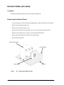
• Place the equipment on a flat stable surface allowing :
−
−
−
−
−
access to the ON/OFF switch,
access to the disk drive,
use of the protection rail,
opening of the printer cover,
circulation of air.
mini API Service Manual V.J 12.96
3-5
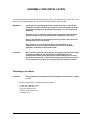
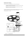
1-Left-hand Roller
2-Optical Switch for Detection of the Strip Tray
3-Right-hand Roller
)LJXUH
6HWWLQIXSWKH6WULS7UD\
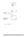
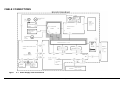
1-Keyboard Cable Connection
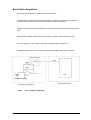
2-Serial Port for Bidirectional Interface
3-Power Cord Connection
4-Printer Connection Box
5-Printer "Reset" Button
6- Printer
)LJXUH
3-6
&RQQHFWLRQV
mini API Service Manual V.J 12.96
6HWWLQJ8SWKH6WULS7UD\
• Place the strip tray between rollers 1 and 3 and gently push it inside the reader (see
Figure 3-1).
&RQQHFWLRQV
• Connect the power cord to the male outlet on the instrument.
• Connect the keyboard cable (see Figure 3-2).
3UHSDULQJIRU2SHUDWLRQ
★ Prior to switching on PLQL$3,, make sure that:
− The AC plug is connected to a grounded outlet.
− Spare fuses with appropriate rating and of specified type are available.
,03257$17
8VLQJUHSDLUHGIXVHVDQGVKRUWFLUFXLWLQJIXVHVLVSURKLELWHG
&$87,21
,QFDVHRILQWHUYHQWLRQE\XQDXWKRULVHGSHUVRQQHOWKH6XSSOLHUUHMHFWV
DQ\UHVSRQVLELOLW\DQGUHVHUYHVWKHULJKWWRFDQFHOWKHZDUUDQW\
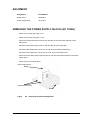
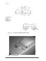
$GMXVWLQJWKH+HLJKWRIPLQL$3,
PLQL$3, is equipped with feet allowing its height to be adjusted (two positions). At the time of
delivery PLQL$3, is set in the highest position.
To ensure correct functioning of the instrument the feet should be adjusted at the time of
installation.
To put PLQL$3, in the lowest position,
• Remove the feet spacers and replace the 4 M5x30 CHC screws with the 4 M5x16 CHC
screws delivered with the instrument.
mini API Service Manual V.J 12.96
3-7
3-8
mini API Service Manual V.J 12.96
&+$37(5
'(6&5,37,212)02'8/(6
,1752'8&7,21
This chapter is structured as follows:
Page
SECTION 4.1
OVERVIEW
SECTION 4.2
0,1,$3,
4-12
SECTION 4.3
POWER SUPPLY BLOCK
4-24
SECTION 4.4
OPTICAL BLOCK
4-38
SECTION 4.5
MANAGEMENT BLOCK
4-60
SECTION 4.6
BORD INTERFACE SERIAL LCD CPU
4-84
SECTION 4.7
COMPUTER BLOCK
4-92
SECTION 4.8
PRINTER BLOCK
mini API Service Manual V.J 12.96
4-5
4-116
4-3
4-4
mini API Service Manual V.J 12.96
6(&7,21 29(59,(:
mini API Service Manual V.J 12.96
overview
4-5
4-6
overview
mini API Service Manual V.J 12.96
6(&7,21&217(176
This section includes:
Page
PRECAUTIONS
4-9
TOOLS
4-10
DISASSEMBLY AND ASSEMBLY
4-11
mini API Service Manual V.J 12.96
overview
4-7
4-8
overview
mini API Service Manual V.J 12.96
This section describes the functions of each module and gives the positions of the modules on the
instrument..It also includes the block diagrams, schematic diagrams, technical drawings and
procedures allowing you to disassemble or assemble the modules and make any mechanical,
electronic or optical adjustments.
35(&$87,216
Take the following precautions before you disassemble or assemble the module.
:$51,1*
%HIRUHGLVDVVHPEOLQJDVVHPEOLQJRUDGMXVWLQJWKHPRGXOHVGLVFRQQHFW
WKHSRZHUVXSSO\FDEOHIURPWKH$&SRZHURXWOHW)DLOXUHWRGRVRPD\
FDXVHSK\VLFDOLQMXU\
&$87,21
7RPDLQWDLQRSWLPXPPRGXOHRSHUDWLRQXVHWKHWRROVUHFRPPHQGHGIRU
PDLQWHQDQFHZRUN$GMXVWHDFKPRGXOHDVGHVFULEHGLQWKLVPDQXDO
%HIRUHDQ\RIWKHIROORZLQJSURFHGXUHVFDQEHSHUIRUPHGPLQL$3,PXVW
EHSDUWLDOO\GLVDVVHPEOHG
mini API Service Manual V.J 12.96
overview
4-9
722/6
Below is a list of the tools recommended for disassembling, assembling or adjusting the
modules. Only use tools that meet these specifications.
7RROV
3DUW1R
2mm Screwdriver
1.5mm Hex key
2.5mm Hex key
3mm Hex key
4mm Hex key
5mm Hex key
5.5mm Wrench
7mm Wrench
60W Soldering iron
Nephelometric kit
99 080
Colorimetric kit
455 0128 A
Screwdriver for adjustment
Tool cleaner
455 0409 A
Antistatic wrist strap
455 0272 A
7DEOH$5HFRPPHQGHGWRROV
'HVFULSWLRQ
6SHFLILFDWLRQV
Multimeter (Fluke or equivalent)
Oscilloscope
20 Mhz
ATB Service software
included in 455 0128 A
Plate of (FROL
Customer’s own
7DEOH%(TXLSPHQWUHTXLUHGIRUPDLQWHQDQFH
4-10
overview
mini API Service Manual V.J 12.96
',6$66(0%/<$1'$66(0%/<
This section describes the procedure for disassembling and assembling the main components of
each module. In general, you can install a component in each module by simply reversing the
procedure for removing it. Therefore this chapter does not give the assembly procedures for all the
cases.
mini API Service Manual V.J 12.96
overview
4-11
6(&7,21 0,1,$3,
4-12
mini API
mini API Service Manual V.J 12.96
mini API Service Manual V.J 12.96
mini API
4-13
6(&7,21&217(176
This section includes:
Page
CABLE CONNECTIONS
4-16
PRINCIPLE OF OPERATION
4-18
• Colorimetric Reading
4-18
• Nephelometric Reading
4-19
REMOVING THE CASING (CASING ASSY) = 452 1040A
4-14
mini API
4-22
mini API Service Manual V.J 12.96
mini API Service Manual V.J 12.96
mini API
4-15
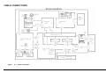
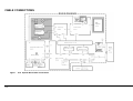
&$%/(&211(&7,216
)LJXUH
4-16
&DEOH&RQQHFWLRQ
mini API
mini API Service Manual V.J 12.96
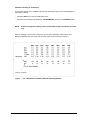
Raw reference
measurementSampling
112 Acquisitions
Raw value
measurementSampling
56 Acqusitions
Raw value
measurementSampling
5 Acqusitions
Smoothing curve based on mobile average at level 5 :
M1+M2+M3+M4+M5
M2+M3’+M4+M5+M6
= M3’
5
= M4’; ect
5
Reference
Ref
Maximum value
Vm
Ref = Ref-Off
2
Vm’ = Vm - Off
Offset
Off
Restored value:
Vr = Vm’ x 209
Ref
)LJXUH
&DOFXODWLRQRI1XPHULFDO9DOXHV
mini API Service Manual V.J 12.96
mini API
4-17
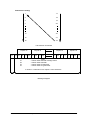
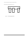
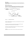
35,1&,3/(2)23(5$7,21
&RORULPHWULF5HDGLQJ
PLQL$3, measures the transmission of light in four regions of the visible spectrum.
% of transmission
Dt Blue
Dt Green
K60
K40
Wavelength (nm)
)LJXUH
7UDQVPLVVLRQJUDSK
Each biochemical test is characterised by four numerical values obtained at the end of the reading
cycle:
1st Stage
Under a K60 filter
− Reading of the strip code
− Measurement of the reference
− Measurement of the values
2nd Stage
Under a K40 filter
− Measurement of the reference
− Measurement of the values
3rd Stage
Under a Dt Blue filter
− Measurement of the reference
− Measurement of the values
4th Stage
Under a Dt Green filter
− Measurement of the reference
− Measurement of the values
5th Stage
4-18
Calculation of the numerical values (see Figure 4-2).
mini API
mini API Service Manual V.J 12.96
1HSKHORPHWULF5HDGLQJ
For each cupule of the strip PLQL$3, performs two types of measurements:
• Turbidimetry: measurement of the intensity of transmitted light (T) which is inversely
proportional to the amount of bacterial growth.
• Nephelometry: measurement of the intensity of light scattered (S) at 30°, directly
proportional to the amount of bacterial growth.
The reader transmits these two values which enable the estimation of the density of bacterial
growth in the medium (turbi-nephelometry) according to the following ratio:
Turbi-nephelometry = S / T x 256.
Light
source
Filter support
Empty
Lens
DT Green
K60
DT Blue
K40
Diaphragm
3&$5'
Tray
ATB
Strip
Photodiodes
Amplifier
Multiplexer
Strip code
$'
Scattered light
Transmitted light
)LJXUH
5HDGLQJ3ULQFLSOH
mini API Service Manual V.J 12.96
mini API
4-19
%ORFN'LDJUDPRI$QDORJXH'LJLWDO&RQYHUWHU
)LJXUH
4-20
$QDORJXH'LJLWDO&RQYHUWHU
mini API
mini API Service Manual V.J 12.96
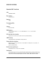
%
$
&
)LJXUH
3RVLWLRQRI&DVWLQJ6FUHZV
mini API Service Manual V.J 12.96
mini API
4-21
Before any of the following procedures can be performed,PLQL$3,must be partially disassembled.
To reach the proper stage of disassembly, proceed as follows:
5(029,1*7+(&$6,1* (CASING ASSY) = 452 1040A
− Pull out the protection rail.
− Remove the tray.
− Remove the three M5x10 CHC screws from the back panel of the instrument (A).
− Remove the two M5x10 CHC screws from the front of the instrument (B).
− Place your hands flat on either side of the instrument and lift off the casing.
:$51,1*
4-22
'RQRWSODFH\RXUILQJHUVXQGHUQHDWKWKHLQVWUXPHQWWROLIWRIIWKHFDVLQJ
mini API
mini API Service Manual V.J 12.96
mini API Service Manual V.J 12.96
mini API
4-23
6(&7,21 32:(56833/<
%/2&.
4-24
Power Supply Block
mini API Service Manual V.J 12.96
mini API Service Manual V.J 12.96
Power Supply Block
4-25
6(&7,21&217(176
This section includes:
Page
CABLE CONNECTIONS
4-28
EQUIPMENT
4-29
REMOVING THE POWER SUPPLY BLOCK (451 1026A)
4-29
BOARD POWER (450 0628A)
4-30
• Location
4-30
• Removing the Board Power
4-30
PRINCIPLE OF OPERATION (POWER SUPPLY BLOCK)
4-32
• Power Supply Circuit Operation
4-32
• Reader Power Supply
4-32
• Computer Power Supply
4-32
PRINCIPLE OF OPERATION (BOARD POWER)
4-33
• Filter Motor Drive Circuit
4-33
• Tray Motor Drive Circuit
4-34
TESTING AND ADJUSTMENT
4-35
• Reader Power Supply
4-35
• Board Power
4-36
• Procedure
4-37
4-26
Power Supply Block
mini API Service Manual V.J 12.96
mini API Service Manual V.J 12.96
Power Supply Block
4-27
&$%/(&211(&7,216
)LJXUH
4-28
3RZHU6XSSO\&DEOH&RQQHFWLRQV
Power Supply Block
mini API Service Manual V.J 12.96
(48,30(17
'HVLJQDWLRQ
3DUW1XPEHU
Board Power
4500628 A
Power Supply Block
4511026 A
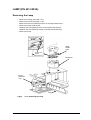
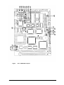
5(029,1*7+(32:(56833/<%/2&.$
− Remove the casing (see page 4-21).
− Remove the printer (see page 4-119).
− Remove the three M4x8 CHC screws from the back of the instrument and take off the
back panel.
− Disconnect the power supply cable on the hard disk and the floppy disk.
− Disconnect the cables from connectors J3 and J9 on the board COM GEST2.
− Disconnect the cables from connectors JC4 and JC5 on the board power.
− Remove the four M4x8 CHC screws located on the right and left-hand sides of the power
supply block.
− Remove the power supply block.
Power Supply Block
4 M3X8 CHC Screws
Bottom
)LJXUH
5HPRYLQJWKH3RZHU6XSSO\%ORFN
mini API Service Manual V.J 12.96
Power Supply Block
4-29
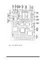
%2$5'32:(5$
/RFDWLRQ
This board is fastened to the front part of the power supply block.
5HPRYLQJWKH%RDUG3RZHU
− It is not necessary to remove the power supply block in order to remove the board power.
− Remove the casing (see page 4-21).
− Remove the printer (see page 4-119).
− Disconnect the cables from connectors JC1, B1, JC4 and JC5 on the board power.
− Disconnect the cables from connector J3 on the COM GEST2 board.
− Remove the three M3x6 CHC screws on the board power.
− Remove the board power.
Power Supply Block
3 CHC (M3X8)
Board Power
)LJXUH
4-30
Bottom
5HPRYLQJWKH%RDUG3RZHU
Power Supply Block
mini API Service Manual V.J 12.96
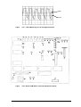
)LJXUH
3RZHU6XSSO\&LUFXLW%ORFN'LDJUDP
mini API Service Manual V.J 12.96
Power Supply Block
4-31
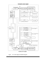
35,1&,3/(2)23(5$7,2132:(56833/<%/2&.
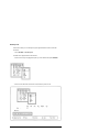
3RZHU6XSSO\&LUFXLW2SHUDWLRQ
Figure 4-10 shows the power supply circuitry in the form of a block diagram.
When AC power enters PLQL$3, from an external power source, the filter circuit removes the
noise.
5HDGHU3RZHU6XSSO\
It provides the board COM GEST2 with stabilised +5VDC and +/- 15VDC from the 220V
mains.
It provides the board power with stabilised +5VDC and +/- 12VDC.
The AC voltage then undergoes full wave rectification and is smoothed to produce direct
current.
A voltage detector circuit is connected to the switching circuit. This feedback control
arrangement ensures a stable voltage supply.
An automatic electronic current-limiting circuit with automatic recovery limits short-circuit
output current to a safe preset value, protecting load and power supply when direct shorts
occur.
It provides the board power with +24VDC to supply motors and +12VDC to supply the lamp.
&RPSXWHU3RZHU6XSSO\
It provides the board CPU, hard disk and floppy disk with stabilised +5VDC and +12VDC.
It provides the printer with +12VDC.
An automatic electronic current-limiting circuit with automatic recovery limits short-circuit
output current to a safe preset value, protecting load and power supply when direct shorts
occur.
4-32
Power Supply Block
mini API Service Manual V.J 12.96
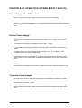
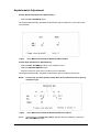
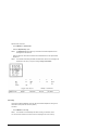
35,1&,3/(2)23(5$7,21%2$5'32:(5
The board power has two main functions:
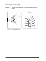
)LOWHU0RWRU'ULYH&LUFXLW
The filter motor, which is a bipolar stepper motor, is used to change the filter during a
colorimetric reading. It advances 3.6° per step.
COM GEST2 U13 circuit ports (PB2, PB4, PB7) are used to control the filter motor.
The filter motor drive circuit (GS D200S) is a complete controller and driver that incorporates
all the power functions to directly interface a microprocessor and a two-phase permanent
magnet motor.
Very little information is sent by the microprocessor to the module.
• Step Clock.
• Direction (Clockwise or counterclockwise CC/CCW).
• Reset and Enable.
Based on this information, the module generates the proper four-phase sequence to directly
drive a two-phase bipolar motor.
The GS D200S incorporates a thermal protection that switches off the power stages when
the junction temperature of active components reaches 150°C.
)LJXUH
)LOWHU0RWRU'ULYHFLUFXLW
mini API Service Manual V.J 12.96
Power Supply Block
4-33
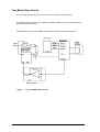
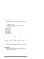
7UD\0RWRU'ULYH&LUFXLW
The tray motor (continuous motor) is used to move the tray in two directions.
The P2 potentiometer allows you to adjust the output voltage to drive the motor and thus
adjust the speed of the tray.
COM GEST2 U13 circuit ports (PB3, PB5, PB1) are used to control the tray motor.
)LJXUH
4-34
7UD\0RWRU'ULYHFLUFXLW
Power Supply Block
mini API Service Manual V.J 12.96
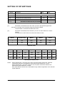
7(67,1*$1'$'-8670(17
Material required:
− Digital multimeter (Fluke 8050A or equivalent).
− Screwdriver for adjustment.
− PLQL$3, maintenance software included in the colorimetric kit (product no. 455 0128A).
5HDGHU3RZHU6XSSO\
Adjustment procedure:
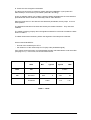
9'&$GMXVWPHQW
− Connect DMM between PT6 (Gnd) and PT1 (24V) on the board power.
− Adjust with the RV1 potentiometer on the power supply block (see Fig. 4-13) so that the
voltage is between 24VDC +/- 0.1V.
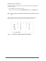
Output Voltage Range
+5V
+/-1%
+15V
+/-1%
-15V
+/-1%
+24V
+/-0.1V
+/-12V
+/-2%
(Non-Adj)
(Non-Adj)
(Non-Adj)
(Adj)
(Non-Adj)
Terminals
+5V
1.5A
+15V 0.3A
-15V 0.3A
+24V 1.5A
+/-12V 2.2A
9'&/DPS$GMXVWPHQW
To adjust the lamp, use the maintenance software (see Chapter 10).
− Adjust RV2 on the power supply block to obtain 11.5V +/- 0.1V.
&$87,21
7DNHPHDVXUHPHQWVGLUHFWO\IURPWKHODPSSLQVRQWKHODPSKROGHUERDUG
Power Supply Block
RV1
RV2
)LJXUH
6ZLWFKLQJ3RZHU6XSSO\&DUG7HVWLQJDQG$GMXVWHPHQW
mini API Service Manual V.J 12.96
Power Supply Block
4-35
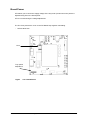
%RDUG3RZHU
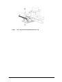
PT3 allows you to control the supply voltage of the tray motor (continuous motor) which is
adjusted using P2 on the board power.
PT3 is not used during the voltage adjustment.
The FU1 fuse protects the +24V on the GS D200S chip against overloading.
− 1A Slow blow fuse .
Fuse
Tray speed
adjustment
)LJXUH
4-36
%RDUG3RZHU
Power Supply Block
mini API Service Manual V.J 12.96
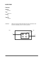
3URFHGXUH
After initialisation of the system and the PLQL$3,maintenance software (see Chapter 10),
follow the instructions below.
On the board COM GEST2:
• Ground of the oscilloscope to PT17.
• Channel A of the oscilloscope to PT33
setup of oscilloscope 2V/div 100ms/div.
− Start a reading using ) and &RORULPHWULFUHDGLQJ of the PLQL$3,maintenance
software.
− Adjust P2 in order to obtain about 200 ms between the gaps of the tray.
− Repeat the operation until you obtain the correct value.
)LJXUH
'LUHFWLRQRIWKH7UD\'7 PVWUD\VSHHG
mini API Service Manual V.J 12.96
Power Supply Block
4-37
6(&7,21 237,&$/%/2&.
4-38
Optical Block
mini API Service Manual V.J 12.96
mini API Service Manual V.J 12.96
Optical Block
4-39
6(&7,21&217(176
This section includes:
Page
CABLE CONNECTIONS
4-42
EQUIPMENT
4-43
REMOVING THE OPTICAL BLOCK
4-43
CONDENSER (P/N 452 0409A)
4-43
• Removing the Condenser
LAMP (P/N 451 0293A)
4-44
4-45
• Removing the Lamp
4-45
• Removing the Lamp (cont’d)
4-46
BOARD OPTIC ACQUISITION (P/N 450 0631A)
4-47
• Location
4-47
• Removing the Board Optic Acquisition
4-47
BOARD DETECTION TRAY (P/N 450 0630A)
4-48
• Location
4-48
• Removing the Board Detection Tray
4-48
BOARD DETECTION FILTER HOLDER (P/N 450 0629A)
− Location
4-49
4-49
• Removing the Board
4-49
PRINCIPLE OF OPERATION
4-50
• Lamp States
4-50
• Board Optic Acquisition
4-51
• Board Detection Tray
4-52
• Board Detection Filter Holder
4-52
TESTING AND ALIGNMENT
4-40
4-53
• Lamp and Condenser
4-53
• Board Optic Acquisition
4-57
• Board Detection Tray
4-58
Optical Block
mini API Service Manual V.J 12.96
mini API Service Manual V.J 12.96
Optical Block
4-41
&$%/(&211(&7,216
)LJXUH
4-42
12.96
2SWLFDO%ORFN&DEOH&RQQHFWLRQV
Optical Block
mini API Service Manual V.J
(48,30(17
'HVLJQDWLRQ
3DUW1XPEHU
Condenser
Colorimetric Tray
Tray Motor ASSY
Filter Motor ASSY
Board Detection Tray
Lamp Holder Board
12V 20W Tungsten Lamp
Board Detection Filter Holder
Board Optic Acquisition
Anticaloric Filter
DT Blue Filter
DT Green Filter
K60 Filter
K40 Filter
452 0409A
452 0406A
451 1031A
451 1030A
450 0630A
450 0283A
451 0293A
450 0629A
450 0631A
452 0361A
452 0365A
452 0364A
452 0363A
452 0362A
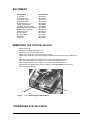
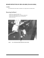
5(029,1*7+(237,&$/%/2&.
−
−
−
−
−
−
−
−
−
−
Remove the tray.
Remove the casing (see page 4-21).
Remove the printer (see page 4-119).
Remove the earth wire on the tray motor assy (A).
Remove the earth wire on the board optic acquisition from the bottom of the instrument
(B).
Disconnect the cables from connectors JC4 and JC5 on the board power.
Disconnect the cable from connector JC1 on the board detection tray.
Disconnect the cable from connector JC4 on the board COM GEST2.
Remove the four HM5 nuts (C) from the bottom of the PLQL$3, (see page 4-20).
Remove the optical block.
%
$
)LJXUH
5HPRYLQJWKH2SWLFDO%ORFN
&21'(16(531$
mini API Service Manual V.J 12.96
Optical Block
4-43
5HPRYLQJWKH&RQGHQVHU
−
−
−
−
−
−
−
−
Remove the casing (see page 4-21).
Remove the printer (see page 4-119).
Remove the optical block (see page 4-42).
Remove the two CHC (M3X8) screws on the protection plate (A).
Remove the protection plate.
Disconnect the cable from connector B1 on the lamp holder board.
Remove the two CHC (M3X8) screws on the condenser (B).
Remove the condenser by pulling it away from the optical block.
$
)LJXUH
4-44
%
5HPRYLQJWKH&RQGHQVHU
Optical Block
mini API Service Manual V.J 12.96
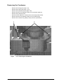
/$0331$
5HPRYLQJWKH/DPS
−
−
−
−
−
−
−
Remove the casing (see page 4-21).
Remove the printer (see page 4-119).
Remove the two CHC (M4X10) screws on the lamp holder board.
Remove the lamp holder board.
Untighten the CHC (M3X6) screws on the square lamp support.
Untighten the CHC (M2X10) screws on the block fixing the lamp.
Remove the lamp.
Lamp CHC (M3X6)
Lamp
Holder
Card
Square Lamp
Support
CHC (M2X10)
Condenser
Board
Detection
Tray
Tray
)LJXUH
5HPRYLQJWKH/DPS
mini API Service Manual V.J 12.96
Optical Block
4-45
5HPRYLQJWKH/DPSFRQW
G
&$87,21
7KHODPSPXVWEHKDQGOHGZLWKFDUH'RQRWWRXFKLWGLUHFWO\ZLWK\RXU
ILQJHUV
&
)LJXUH
4-46
+DQGOLQJWKH/DPS
Optical Block
mini API Service Manual V.J 12.96
%2$5'237,&$&48,6,7,2131$
/RFDWLRQ
The board is fastened underneath the optical block.
5HPRYLQJWKH%RDUG2SWLF$FTXLVLWLRQ
−
−
−
−
Remove the casing (see page 4-21).
Remove the optical block (see page 4-42).
Remove the three CHC (M3X6) screws underneath the optical block (A).
Remove the board.
$
)LJXUH
5HPRYLQJWKH%RDUG2SWLF$FTXLVLWLRQ
mini API Service Manual V.J 12.96
Optical Block
4-47
%2$5''(7(&7,2175$<31$
/RFDWLRQ
The board is fastened on the left-hand side of the lower plate of the optical block.
5HPRYLQJWKH%RDUG'HWHFWLRQ7UD\
−
−
−
−
Remove the casing (see page 4-21).
Remove the cable from the JC1 connector on the board (1).
Remove the CHC (M3X20) screw on the board detection tray support (A).
Remove the 2 CHC (M3x6) screws to separate the support from the board (B).
%
-&
$
)LJXUH
4-48
5HPRYLQJWKH%RDUG'HWHFWLRQ7UD\
Optical Block
mini API Service Manual V.J 12.96
%2$5''(7(&7,21),/7(5+2/'(531$
/RFDWLRQ
The board detection filter holder is fastened on the upper plate of the optical block.
5HPRYLQJWKH%RDUG
−
−
−
−
Remove the casing (see page 4-21).
Remove the cable from the JC1 connector on the board.
Remove the 2CHC (M3X6) screws on the board (A).
Remove the board.
$
)LJXUH
5HPRYLQJWKH%RDUG'HWHFWLRQ)LOWHU+ROGHU
mini API Service Manual V.J 12.96
Optical Block
4-49
35,1&,3/(2)23(5$7,21
/DPS6WDWHV
The ports (1PA7, 1PB0) on the board COM GEST2 (U13) circuit are used to control the
voltage lamp.
The Zener diode allows you to maintain a voltage of 2V during standby.
The Tungsten lamp provides the light source during reading of the strip. It has three states
controlled by the firmware.
/DPSVZLWFKHGRII:
-
When switching on, before initialisation.
After 5 mins on standby.
-
BOARD
COM
GEST 2
/DPSRQVWDQGE\
-
After the reading, the lamp remains on standby for
5 minutes. If there are no other readings, it
switches off.
/DPSVZLWFKHGRQ
-
During a reading.
When starting a reading, if the lamp has been
switched off it needs 5 seconds to reach the
operating temperature. These 5 seconds are not
necessary if the lamp has been on standby.
Power supply block
INHIB
1 PA7
INH
1 PB0
PROG
PROG
U13
RV2
Board power
LAMP
)LJXUH
4-50
/DPS&RQWURO'ULYH&LUFXLW
Optical Block
mini API Service Manual V.J 12.96
%RDUG2SWLF$FTXLVLWLRQ
The board optic acquisition iscentred under the condenser.
Via photodiodes, the light transmitted and scattered through the cupules is transformed into
an electrical measurement which is transmitted to the board COM GEST2.
Reading of the strip code and colorimetric reading are performed with the normal gain (switch
OFF).
Nephelometric reading is performed with a quarter of the gain of the colorimetric mode.
The CA2 signal is UP, the switch is ON and the amplifier gain is divided by 4.
Analogical switching only occurs with the central photodiodes and the strip code diode.
Analogical Switch
CA2
220K
680K
U13
Central photodiode
Board optic acquisition
)LJXUH
Board Com Gest 2
$QDORJLFDO6ZLWFKLQJ
mini API Service Manual V.J 12.96
Optical Block
4-51
%RDUG'HWHFWLRQ7UD\
This board enables the detection of the gaps of the tray’s setting stick. The electrical
information collected on this board goes to the board COM GEST2.
+5 V
1PA2
U24
U13
Optical interrupt
Board Com Gest 2
)LJXUH
%RDUG'HWHFWLRQ7UD\&LUFXLW
%RDUG'HWHFWLRQ)LOWHU+ROGHU
This board enables the detection of the pin placed on the filter holder cylinder. The
information picked up by the detector goes to the board COM GEST 2 via the board power.
1PA0
IC8-b
Board Power
U13
Optical interrupt
Board Com Gest 2
)LJXUH
4-52
%RDUG'HWHFWLRQ)LOWHU+ROGHU&LUFXLW
Optical Block
mini API Service Manual V.J 12.96
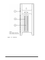
7(67,1*$1'$/,*10(17
Material required:
− Digital multimeter (Fluke 8050A or equivalent)*.
− Screwdriver for adjustment.
− Maintenance software.
*Equipment must bear a valid calibration sticker.
&$87,21
7KHSRZHUVXSSO\PXVWEHDGMXVWHGEHIRUH\RXSHUIRUPWKHFRQGHQVHU
DOLJQPHQW
,I\RXPDNHDQ\PRGLILFDWLRQVWRWKHFRQGHQVHUDOLJQPHQW\RXDUH
REOLJHGWRFDUU\RXWQHSKHORPHWULFDGMXVWPHQWV
/DPSDQG&RQGHQVHU
NOTE : Perform the procedure below only if necessary (bad alignment between the lamp,
the diaphragm and the board optic acquisition).
Adjustment Procedure:
★ After initialisation of the system and the maintenance software (see Chapter 10):
−
−
−
−
Remove the tray.
Light up the lamp using the maintenance software.
Untighten the two screws fixing the diaphragm on the condenser (1).
Adjust the position of the beams as shown in Figure 4-28 with the diaphragm (2) to obtain
correct focus.
)LJXUH
%HDP$OLJQPHQW
mini API Service Manual V.J 12.96
Optical Block
4-53
★ Adjust the lamp holder board as follows:
On the board COM GEST2:
− Ground of the oscilloscope to PT17.
− Channel 1 of the oscilloscope to PT20 (left central photodiode signal).
− Channel 2 of the oscilloscope to PT22 (right central photodiode signal).
The lamp is switched on using the ) function of the maintenance software.
− Perform the alignment under K60 filter using the ) command.
− Find the position of the untightened lamp holder board allowing you to obtain the same
signal on the left and right channels.
− The signal must have maximum amplitude.
− Check the alignment under each filter using the ) command (equal signals).
− Block the lamp holder board by tightening the two fixing screws.
NOTE : The amplitudes of the signals are different with each filter.
★ Perform the colorimetric adjustment again using the maintenance software (see page 1013).
− Put the tray back into position.
− Run the colorimetric adjustment menu.
− Check the reference values which should be between 130 and 200.
− Under each filter, the difference between the Min and Max values must be <10.
4-54
Optical Block
mini API Service Manual V.J 12.96
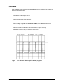
★ Check the strip code and initialisation signal as follows:
On the board COM GEST2:
− Ground of the oscilloscope to PT17.
− INV Channel 1 of the oscilloscope to PT2 (strip code photodiode signal).
− Place an ATB ANA strip with 2 supplementary tests on the tray.
− Start a nephelometric reading cycle.
− Using the oscilloscope, save the signal during the first entry of the tray under the K60
filter.
You should obtain the signal shown in the following diagram.
)LJXUH
6WULS&RGH5HDGLQJ
Large Hole
Small Hole
VGT
PT2 signal
)LJXUH
2VFLOORJUDPDQG+ROHVRQWKH7UD\
mini API Service Manual V.J 12.96
Optical Block
4-55
★ Check the code recognition thresholds
The large hole of the tray is used as a marker during the initialisation cycle (under W.F:
without Filter) or as an end of cycle marker (Under W.F and DTg).
In fact, its diameter allows you to obtain a greater voltage amplitude with the code detection
photodiode than with a small hole classically used for code detection.
When the large hole is in line with the code detection photodiode, the tray stops. It is in its
home position.
The detection thresholds of the holes are fixed by the reader’s firmware. They cannot be
modified.
The reader is working properly when the signals measured for each hole are within the limits
shown in Table C.
To obtain values within the limits, perform the alignment of the lamp and condenser.
On the board COM GEST2:
− Ground of the oscilloscope to PT17.
− INV Channel 1 of the oscilloscope to PT2 (strip code photodiode signal).
If the values exceed the limits, you should adjust the strip code attenuations under each filter
(see page 10-11). In this case, use PT 36 instead of PT2.
93W
&RGH
K60
,QLW
W.F/DTG
Threshold
/DUJH+ROH
6PDOO+ROH
0LQ7\SLFDO
7\SLFDO0D[
3.5V5V
6.5V
8
5.85V
3.5V
5V
1.1V
1.4V
7DEOH&/LPLWV
4-56
Optical Block
mini API Service Manual V.J 12.96
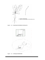
%RDUG2SWLF$FTXLVLWLRQ
&$87,21
&KDQJLQJWKHERDUGLQYROYHVDOLJQPHQWRIWKHFRQGHQVHU7RSHUIRUPWKLV
DOLJQPHQWVHHWKHSURFHGXUHRQSDJH
Material required:
− 2.5mm BTR spanner.
− Maintenance software.
− Oscilloscope.
Alignment Procedure:
★ After initialisation of the system and the maintenance software (see Chapter 10), follow
the instructions below:
−
−
−
−
−
−
Remove the tray.
Untighten the three screws fixing the board optic acquisition.
Light up the lamp using the PLQL$3, maintenance software.
Move the board to obtain a good halo (see Figure 4-31).
Tighten the fixing screws.
Perform the condenser alignment again (see page 4-52).
Beams
)LJXUH
Beams
3RVLWLRQRIWKH%HDPV
mini API Service Manual V.J 12.96
Optical Block
4-57
%RDUG'HWHFWLRQ7UD\
&$87,21
%HIRUHSHUIRUPLQJWKHERDUGGHWHFWLRQWUD\DOLJQPHQWDGMXVWWKHVSHHGRI
WKHWUD\SDJH
Material required:
− Maintenance software.
− Oscilloscope.
Procedure:
★ After initialisation of the system and the maintenance software (see Chapter 10), follow
the instructions below:
★ On the board COM GEST2:
− Ground of the oscilloscope to PT17.
− Channel A of the oscilloscope to PT33.
Set-up of oscilloscope 2V/div 100 ms/div.
− Start a reading using ) and &RORULPHWULFUHDGLQJ of the maintenance software (in the
ATB 1525 module).
★ Check the maximum position.
− After a reading, using the ) $ODUP and 0D[LPXPSRVLWLRQ of the maintenance software,
check that the average of the acquisition point values (POS column) is between 18 and
38.
5HVXOW
:LWKLQWKHUDQJH
The alignment has been done.
2XWVLGHWKHUDQJH
A) Untighten the fixing screw on the supporting block (1).
B) Slowly move the board detection tray (2) ,1 or 287 according to the maximum position
values (see Figure 4-32).
C) Start a reading again and check the maximum position until you obtain the right value.
4-58
Optical Block
mini API Service Manual V.J 12.96
)LJXUH
$OLJQHPHQWRIWKH%RDUG'HWHFWLRQ7UD\
mini API Service Manual V.J 12.96
Optical Block
4-59
6(&7,21 0$1$*(0(17
%/2&.
4-60
Management Block
mini API Service Manual V.J 12.96
mini API Service Manual V.J 12.96
Management Block
4-61
6(&7,21&217(176
This section includes:
Page
CABLE CONNECTIONS
4-64
EQUIPMENT
4-65
REMOVING THE BOARD COM GEST2
4-65
PRINCIPLE OF OPERATION
4-66
• RS 232 Serial Communication
4-68
• EPROM Version Communication
4-68
• Checking the position of the Protection Rail
4-68
• Reading Mode
4-68
• Reading
4-69
• Alarm Messages
4-71
TESTING AND ALIGNMENT
4-73
• Management Card
4-73
• Compensation Adjustment
4-74
• Colorimetric Adjustment
4-74
• Nephelometric Adjustment
4-77
4-62
Management Block
mini API Service Manual V.J 12.96
mini API Service Manual V.J 12.96
Management Block
4-63
&$%/(&211(&7,216
)LJXUH
4-64
0DQDJHPQW%ORFN&DEOH&RQQHFWLRQV
Management Block
mini API Service Manual V.J 12.96
(48,30(17
'HVLJQDWLRQ
3DUW1XPEHU
Board COM GEST2
450 0627A
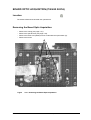
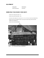
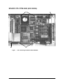
5(029,1*7+(%2$5'&20*(67
− Remove the casing (see page 4-21).
− Remove the printer (see page 4-119).
− Disconnect the cables from connectors J3, J4, J6, J7 and J9 on the board COM GEST2.
− Remove the two CHC (M3x8) screws on the top of the board fixing the board COM
GEST2 to the support (A).
− Remove the board COM GEST2.
$
)LJXUH
5HPRYLQJWKH%RDUG&20*(67
mini API Service Manual V.J 12.96
Management Block
4-65
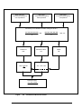
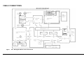
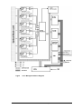
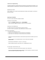
35,1&,3/(2)23(5$7,21
The board COM GEST2 allows reader management and data acquisition from the optical
block.
Information on components:
− 8-bit 6809-type microprocessor
− 4 Mhz frequency
− 64 Kb of static RAM
− 8 Kb of EPROM
− X Kb of EEPROM
− 2 VIA
− 2 ACIA
− 12-bit Analogue-Digital Converter
4-66
Management Block
mini API Service Manual V.J 12.96
)LJXUH
0DQDJHPHQW%ORFN'LDJUDP
mini API Service Manual V.J 12.96
Management Block
4-67
566HULDO&RPPXQLFDWLRQ
The computer module manages the communication. It sends commands to the reader
module which answers back.
A command is therefore the connection from the computer module to the reader module and
an answer is the connection from the reader module to the computer module.
If the reader module is not ready or if it does not understand the message it sends a NACK to
the computer module .
(35209HUVLRQ&RPPXQLFDWLRQ
The computer module asks for the version:
67;0(7; for the EPROM Board COM GEST2
The reader module answers:
67;BBBB(7; (E.g. : 67;(7;).
&KHFNLQJWKHSRVLWLRQRIWKH3URWHFWLRQ5DLO
67;%(7;
The reader module answers: 67;(7; if the protection rail is in.
The reader module answers: 67;(7; if the protection rail is out.
,QLWLDOLVDWLRQRIWKH5HDGHU0RGXOH
Software initialisation:
Instrument operating:
Instrument waiting:
67;K(7;
67;,(7;
67;2(7;
The reader module answers:
The reader module answers:
The reader module answers:
&5
67;,(7;
67;2(7;
NOTE : After initialisation with <h>, operate the instrument by sending the 67;,(7; order.
5HDGLQJ0RGH
− Selection
4-68
SELECTION
SELECTION COMMAND
RETURN MESSAGE IF
READER IS READY
Nephelometry
Colorimetry
67;1(7;
67;&(7;
67;1(7;
67;&(7;
Automatic
recognition
67;$(7;
67;$(7;
Management Block
mini API Service Manual V.J 12.96
− Selected Reading
The computer module asks which reading has been selected:
67;/(7;
The reader module answers:
67;1(7; if nephelometric
67;&(7;if colorimetric
67;$(7; if automatic
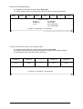
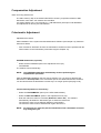
5HDGLQJ
Each value transmitted is right-adjusted and includes 3 characters.
The command for starting the cycle is: 67;'(7;
At the end of the cycle the reader sends values according to the diagram below (except when
the motor alarm "PLQL$3,RXWRIRUGHU" is set, in which case it answers: 67;+(7;&5).
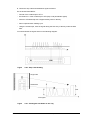
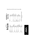
1HSKHORPHWULFUHDGLQJ
1
17
2
18
3
19
4
20
14
30
15
31
16
32
Tansmission Command
BL
BH
L1
C1
L17
C17
L2
C2
L18
C18
L3
C3
----
L16 C16 L32 C32
Message Diagram
mini API Service Manual V.J 12.96
Management Block
4-69
&RORULPHWULFUHDGLQJ
1
17
2
18
3
19
4
20
14
30
15
31
16
32
Transmission Command
Cupule 17
B
BH F1
F2
F1
F2
F3
F4
F3
Cupule 18
F4
F1
F2
F3
Cupule 15
F4
F1
F2
F3
Cupule 16
F4
F1
F2
F3
Data
: Values under K60 filter carriage return
: Values under K40 filter
: Values under DT blue filter
: Values under DT green filter
4 values x 3 characters x 32 cupules = 384 characters
Message Diagram
4-70
Management Block
mini API Service Manual V.J 12.96
F4
$ODUP0HVVDJHV
The computer module asks for alarm messages : 67;((7;
The reader module sends the alarm position according to the following diagram:
67;$$$$$(7;
Alarms 1 to 5 (see diagram)
'HILQLWLRQ
: no alarm
: alarm ON
7ULJJHU
)RUPDW
A1
Bad data transmission.
STX 10000 ETX
A2
Offset alarm.
STX 01000 ETX
A3
Reference values alarm.
A4
Maximum position of the
95-220
STX 00100 ETX
STX 00010 ETX
Acquisition points alarm.
A5
STX 00001 ETX
Bad initialisation of motor.
Reader out of service.
A2, A3 and A4 alarms only concern colorimetry.
When one of these alarms is on, the computer module may have access to the different
corresponding values.
2IIVHW9DOXHV (Message A2)
The computer module asks for these values : 67;(7;
The reader module answers by sending the values according to the following diagram.
ROF1
ROF2
ROF3
ROF4
LOF1
Offset values
R: Right
O: Offset
L: Left
LOF2
LOF3
LOF4
F1: K60 filter
F2: K40 filter
F3: DT blue filter
F4: DT green filter
8 values x 3 characters = 24 characters
mini API Service Manual V.J 12.96
Management Block
4-71
5HIHUHQFH9DOXHV (Message A3)
The computer module asks for these values: 67;(7;
The reader module answers by sending the values according to the following diagram.
RRF1
RRF2
RRF3
RRF4
LRF1
LRF2
LRF3
LRF4
Reference values
R: Right
F1: K60 filter
R:Reference
F2: K40 filter
L: Left
F3: DT blue filter
F4: DT green filter
8 values x 3 characters = 24 characters
3RVLWLRQRIWKHPD[LPXPYDOXHLQWKHDFTXLVLWLRQVLJQDO
The computer module asks for maximum value positions: 67;(7;
The reader module answers by sending the positions according to the following diagram.
The transmission order is the same as for colorimetry.
Cupule 17
Cupule 18
----------
Cupule 15
Cupule 16
P17
P18
----------
P15
P16
P:
Maximum position
32 values x 2 characters = 64 characters
4-72
Management Block
mini API Service Manual V.J 12.96
7(67,1*$1'$/,*10(17
Material required:
−
−
−
−
−
Screwdriver for adjustment.
Maintenance software.
Nephelometric kit
Colorimetric kit
Petri dish of E. coli
&$87,21
7RDGMXVWWKHERDUG&20*(67\RXVKRXOGDGMXVWWKHSRZHUVXSSO\DQG
DOLJQPHQWEHIRUHKDQG
:$51,1*
7RSHUIRUPWKHDGMXVWPHQWSURFHGXUHEHORZ\RXVKRXOGSUHSDUHGLIIHUHQW
LQRFXODWHGVWULSVDVIROORZV
6HWWKHVSHFWURSKRWRPHWHUWRZDYHOHQJWKQPRUXVLQJDGHQVLWRPHWHU
8VLQJD3HWULGLVKRI(FROLDQGDQDPSRXOHRI$8;0HGLXPSUHSDUHD
VXVSHQVLRQIRU
2'VWULS
2'VWULS
2'VWULS
(DFKVWULSVKRXOGEHXVHGIRUWKUHHPHDVXUHPHQWVRQO\
7KHVWULSVPXVWEHXVHGZLWKLQPLQXWHVRILQRFXODWLRQ
NOTE : Below is data on optical densities and their corresponding LEDs.
2'
'HQVLWRPHWHU
'(16,0$7
0.3
LED 21
1.6 McF
0.6
LED 25
2.6 McF
1
LED 28
4.2 McF
0DQDJHPHQW&DUG
9ROWDJH9$GMXVWPHQW
This adjustment allows you to obtain one precise voltage for +V and -V used for adjustment
of OFFSETS.
Adjustment procedure:
− Connect DMM between P17 (AGND) and PT16 (+V) on the board COM GEST2.
− Adjust the P9 potentiometer on the board COM GEST2 until you obtain the voltage
+5VDC +/- 0.01 V.
− Connect the positive probe of DMM to PT18 (-V0) and the ground probe to PT17 on the
board COM GEST2.
− Make sure that the voltage of -V0 is -5VDC +/- 0.01V.
− Repeat this procedure until you obtain the right values.
mini API Service Manual V.J 12.96
Management Block
4-73
&RPSHQVDWLRQ$GMXVWPHQW
6WDWLF$FFXUDF\SHUIRUPDQFH
The AD7111KN (U 26) on the board COM GEST2 accuracy is specified relative to 0dB
attenuation, with "Gain" trim resistors P10 and R49.
It is used to adjust Vout = Vin precisely (i.e., 0dB attenuation) with input code 00000000.
This adjustment is done by the manufacturer.
&RORULPHWULF$GMXVWPHQW
Adjustment Procedure:
After initialisation of the system and the Maintenance Software (see Chapter 10), follow the
instructions below.
− First of all the FILTRO.DAT file from the maintenance software must be updated with the
values written on the neutral filter (colorimetric kit) (see Chapter 10).
(3520,QLWLDOLVDWLRQRSWLRQDO
− Select the INIT E2PROM option in the adjustment menu (F2).
− Init E2PROM.
The software runs automatically.
127( 7KH(3520LQLWLDOLVDWLRQDXWRPDWLFDOO\LQYROYHVSHUIRUPLQJWKH
QHSKHORPHWULFSURFHGXUH
After the E2PROM initialisation the tray may be ejected. If so, you have to decrease the
attenuation in "6HWVWULSFRGH" in the colorimetric part of the 1525N maintenance software.
You should decrease the attenuation until the tray is no longer ejected (see page 4-55).
&HQWUDO*DLQ$GMXVWPHQWLQ&RORULPHWU\
− Select the &2/25,0(75< option (in the ATB 1525N module).
− Select the 6(7$8720$7,& option in the adjustment menu (F2).
− Enter the reference value for each filter (5HIHUHQFHYDOXH). The software
automatically calculates the attenuation gain to obtain the references.
The reference value can be different (between 130 and 200).
The reference value must be obtained with a gain other than 0.
127( )RUWKLVVWHS\RXPXVWQRWSXWWKHQHXWUDOILOWHURIWKHFRORULPHWULFNLWRQWKH
WUD\GXULQJWKHF\FOH
4-74
Management Block
mini API Service Manual V.J 12.96
)LJXUH
0DLQWHQDQFH6RIWZDUH:LQGRZUHIHUHQFH2SWLRQ
NOTE : If the message7DUJHWYDOXH287" appears after the calibration, repeat the
SET AUTOMATIC option.
7UD\,QLWLDOLVDWLRQ
− Select the ,1,775$< option in the calibration menu.
The software automatically initialises the tray (it takes a tray image).
,03257$17
,QRUGHUWRVWRUHWKHYDOXHV\RXPXVWSHUIRUPWKHYDOLGDWLRQUHDGLQJ
mini API Service Manual V.J 12.96
Management Block
4-75
9DOLGDWLRQ5HDGLQJLQ&RORULPHWU\
This function allows you to validate and store the attenuation gains in the E2PROM after a
colorimetric reading.
− Press the(6& key to exit the calibration menu.
− Press the ) command and select the &2/25,0(75,& option in the 5($',1* menu.
127( %HIRUHUXQQLQJWKHUHDGLQJSXWWKHQHXWUDOILOWHURIWKHFRORULPHWULFNLWRQWKH
WUD\
After the reading, check that the values are correct (see example in table below). The
difference between the Ave value and the Filter value should not be more than 2.
)LJXUH
4-76
0DLQWHQDQFH6RIWZDUH:LQGRZ5HDGLQJ2SWLRQ
Management Block
mini API Service Manual V.J 12.96
1HSKHORPHWULF$GMXVWPHQW
&HQWUDO2IIVHWV$GMXVWPHQWIRU1HSKHORPHWU\
− Select the $'-2))6(76 option.
The software automatically calculates the attenuation gain to obtain the correct values with
central offsets.
)LJXUH
0DLQWHQDQFH6RIWZDUH:LQGRZ2IIVHW2SWLRQ
&HQWUDO*DLQ$GMXVWPHQWLQ1HSKHORPHWU\
− Select the 6(7$8720$7,& option in the calibration menu.
− Select the 1(3+(/20(75< option.
− Enter the reference value which is written on the neutral filter.
The software automatically calculates the attenuation gain to obtain the references.
127( )RUWKLVVWHS\RXPXVWSXWWKHQHXWUDOILOWHURIWKHFRORULPHWULFNLWRQWKHWUD\
GXULQJWKHF\FOH
)LJXUH
0DLQWHQDQFH6RIWZDUH:LQGRZ5HIHUHQFH2SWLRQ
NOTE : If the message7DUJHWYDOXH287" appears after the calibration, repeat the
6(7$8720$7,& option.
mini API Service Manual V.J 12.96
Management Block
4-77
9DOLGDWLRQ5HDGLQJLQ1HSKHORPHWU\
This function allows you to validate and store the attenuation gains in the E2PROM after a
nephelometric reading.
− Press the (6& key to exit the calibration menu.
− Press the ) command and select the 1(3+(/20(75< option in the 5($',1* menu.
127( %HIRUHUXQQLQJWKHUHDGLQJSXWWKHQHXWUDOILOWHURIWKHFRORULPHWULFNLWRQWKH
WUD\
After the reading, check that the values are correct (see example in table below). The
difference between the Ave value and the Filter value should not be more than 2.
)LJXUH
4-78
0DLQWHQDQFH6RIWZDUH:LQGRZ5HDGLQJ2SWLRQ
Management Block
mini API Service Manual V.J 12.96
Rear
Front
)LJXUH
/DWHUDO%DODQFLQJRI/HIWDQG5LJKW&KDQQHOV
)LJXUH
%RDUG&20*(677HVWDQG$GMXVWPHQWVSRLQWV
mini API Service Manual V.J 12.96
Management Block
4-79
/DWHUDO*DLQLQ1HSKHORPHWU\
To adjust the lateral gain, carefully follow the instructions in the maintenance software. The
software programs for adjustment in colorimetric and nephelometric mode are not the same.
Adjustment Procedure:
After initialisation of the system and the Maintenance Software (see Chapter 10), follow the
instructions below.
$GMXVWLQJWKH2))6(76
Use the ATB 1525 Maintenance Software module.
$GMXVWLQJWKH/DWHUDO2IIVHWV
− Select the /$7(5$/2))6(76 option in $'-8670(17.
− Adjust with 3 and 3 potentiometers to obtain the value in brackets.
$GMXVWLQJWKH/DWHUDO%DODQFLQJ.
★ Adjust the left channel lateral balancing signals as follows:
Use the ATB 1525 N (colorimetric option) Maintenance Software module.
On the board COM GEST2:
• Ground of the oscilloscope to PT17.
• Channel A of the oscilloscope to PT5 (Lateral left rear photodiode).
• Channel B of the oscilloscope to PT8 (Lateral left front photodiode).
− Turn the P1 and P2 potentiometers counterclockwise (decrease the resistance) as far as
possible.
− Carry out one turn in a clockwise direction on each of the above-mentioned
potentiometers.
− Put the strip inoculated with (FROL (O.D. 1) on the tray.
− Select the balancing option (Later. Bal.) from the ) adjustment menu.
The tray begins a back and forth cycle.
− Detect which channel gives the lowest level signal on the oscilloscope.
− Turn the corresponding potentiometer clockwise so that the signals on channels A and B
of the oscilloscope are equal (see Figure 4-41).
4-80
Management Block
mini API Service Manual V.J 12.96
★ Adjust the right-hand channel lateral balancing signals as follows:
On the management card:
• Ground of the oscilloscope to PT17.
• Channel A of the oscilloscope to PT11 (Lateral right rear photodiode).
• Channel B of the oscilloscope to PT14 (Lateral right front photodiode).
− Turn the P5 and P6 potentiometers counterclockwise (decrease the resistance) as far as
possible.
− Carry out one turn in a clockwise direction on each of the above-mentioned
potentiometers.
− Put the strip inoculated with (FROL (O.D. 1) on the tray.
− Select the balancing option (Later. Bal).
The tray begins a back and forth cycle.
− Detect which channel gives the lowest level signal on the oscilloscope.
− Turn the corresponding potentiometer clockwise so that the signals on channels A and B
of the oscilloscope are equal (see Figure 4-41).
mini API Service Manual V.J 12.96
Management Block
4-81
$GMXVWLQJWKH/DWHUDO*DLQVLQ'\QDPLF5HDGLQJ
Use the ATB 1525 Maintenance Software module.
− Put an inoculated strip (O.D 0.6 - 135 µl) on the tray.
− Select the option )5HDGLQJ and 1(3+(/20(75,& 5HDGLQJ mode.
− Start a reading.
As soon as the reading is over,
− Interpret the table in the Help Menu (by pressing )).
− Adjust potentiometers 3 and 3 for Lateral Gains to obtain the correct values (see Table
D).
− Repeat the last three steps until you obtain the right values. If necessary (after three
readings) inoculate another strip.
Once the adjustment has been performed, the reading of an inoculated strip with an O.D. of
0.3 will confirm it.
To check, use the procedure for Lateral Gains in Dynamic Reading and refer to Table E.
2'
$YHUDJH
9DU0D[L
0LQL
0D[L
&HQWUDO
--
8
--
--
/DWHUDO
88/98
4
--
--
'LYLVLRQ
130/150
7
120
160
7DEOH'+HOS7DEOHIRU2'6WULS
2'
$YHUDJH
9DU0D[L
&HQWUDO
--
--
--
--
/DWHUDO
--
--
--
--
70/85
6
60
93
'LYLVLRQ
0LQL
0D[L
7DEOH(+HOS7DEOHIRU2'6WULS
4-82
Management Block
mini API Service Manual V.J 12.96
mini API Service Manual V.J 12.96
Management Block
4-83
6(&7,21 %25',17(5)$&(
6(5,$//&'&38
4-84
Bord Interface Serial LCD CPU
mini API Service Manual V.J 12.96
mini API Service Manual V.J 12.96
Bord Interface Serial LCD CPU
4-85
6(&7,21&217(176
This section includes:
Page
REMOVING THE BOARD INTERFACE (450 0625A)
4-88
CABLE CONNECTIONS
4-89
PRINCIPLE OF OPERATION
4-90
4-86
Bord Interface Serial LCD CPU
mini API Service Manual V.J 12.96
$
)LJXUH
5HPRYLQJWKH%RDUG,QWHUIDFH
mini API Service Manual V.J 12.96
Bord Interface Serial LCD CPU
4-87
5(029,1*7+(%2$5',17(5)$&($
− Remove the casing (page 4-21).
− Disconnect the cables from connectors J10, J1, J5, J2, J7, J9 and J6 on the board
interface serial LCD CPU.
− Remove the 3 MXx6 CHC screws (A).
− Remove the board.
4-88
Bord Interface Serial LCD CPU
mini API Service Manual V.J 12.96
&$%/(&211(&7,216
)LJXUH
%RDUG,QWHUIDFH6HULDO/&'&83&DEOH&RQQHFWLRQV
mini API Service Manual V.J 12.96
Bord Interface Serial LCD CPU
4-89
35,1&,3/(2)23(5$7,21
The Board Interface Serial LCD CPU has 3 main functions.
1) It is connected to the Board CPU PCM 4860 via the J2 connector and receives the
following data:
− - presence of a power supply indicated by the green LED.
− - hard disk operating: orange LED.
− - signals for the speakers.
If you touch SW1, the microprocessor will reset.
2) Via J1, J6, J7 the board dispatches data required by the screen.
The integrated power supply (U1) supplies current of _ 17.7 V to the screen.
The P1 and P2 potentiometers enable you to adjust the contrast and brightness of the
screen.
3) Via J5 and J8 the board ensures the RS 232 connection between the Board COM GEST2
and the Board CPU PCM 4860. This function also includes filtering of signals (EMC
standard).
4-90
Bord Interface Serial LCD CPU
mini API Service Manual V.J 12.96
mini API Service Manual V.J 12.96
Bord Interface Serial LCD CPU
4-91
6(&7,21 &20387(5
%/2&.
4-92
Computer Block
mini API Service Manual V.J 12.96
mini API Service Manual V.J 12.96
Computer Block
4-93
6(&7,21&217(176
This section includes:
Page
CABLE CONNECTIONS
4-95
CENTRAL PROCESSING UNIT
4-96
BOARD CPU PCM 4860 (450 0626A)
4-97
INTRODUCTION
4-98
• Safety Precautions
4-98
• Removing the Board CPU PCM 4860 (450 0626A)
4-98
SPECIFICATIONS
4-99
• Standard SBC functions
− Max. power requirements
4-99
4-100
JUMPERS AND CONNECTORS
4-102
SIMM MEMORY MODULES
4-105
DETAILED INFORMATION ON SERIAL PORTS
4-106
JUMPER SETTINGS
4-108
FLOPPY DRIVE
4-109
• Features
4-109
HARD DISK
4-110
• Features
4-110
DISPLAY
4-112
• Mechanical Data
4-112
• Removing the Display (451 1023A)
4-112
CABLE CONNECTIONS
4-94
4-113
• Electrical Absolute Maximum Ratings
4-114
• Environmental Absolute Maximum Ratings
4-114
• Electrical Characteristics of Backlight
4-115
• Precautions for Use
4-115
• Storage
4-115
• Safety
4-115
Computer Block
mini API Service Manual V.J 12.96
&$%/(&211(&7,216
)LJXUH
&RPSXWHU&DEOH&RQQHFWLRQV
mini API Service Manual V.J 12.96
Computer Block
4-95
&(175$/352&(66,1*81,7
The Central Processing Unit (CPU) is installed on the CPU board.
It is:
ST 486 DX2-66 MHz
Voltage: 5 VDC.
4-96
Computer Block
mini API Service Manual V.J 12.96
%2$5'&383&0$
%
$
%
$
)LJXUH
5HPRYLQJWKH%RDUG&383&0
mini API Service Manual V.J 12.96
Computer Block
4-97
,1752'8&7,21
The PCM-4860 is an all-in-one single board computer that provides a compact, complete, highperformance, PC/AT compatible system.
The PCM-4860 comes equipped with a 486 CPU. It features two 72-pin DRAM SIMM sockets, an
IDE hard disk controller, a floppy disk controller, two serial ports, and a bi-directional parallel port.
6DIHW\3UHFDXWLRQV
Follow these simple precautions to protect yourself from harm and your system from damage.
:$51,1*
7RDYRLGHOHFWULFVKRFNDOZD\VGLVFRQQHFWWKHSRZHUIURP\RXUV\VWHP
FKDVVLVEHIRUH\RXZRUNRQLW'RQRWWRXFKDQ\FRPSRQHQWVRIWKHERDUG
RURWKHUFDUGVZKLOHWKH3&LVRQ
'LVFRQQHFWSRZHUEHIRUHPDNLQJDQ\FRQILJXUDWLRQFKDQJHV7KHVXGGHQ
UXVKRISRZHUDV\RXFRQQHFWDMXPSHURULQVWDOODFDUGPD\GDPDJH
VHQVLWLYHHOHFWURQLFFRPSRQHQWV
$OZD\VJURXQG\RXUVHOIWRUHPRYHDQ\VWDWLFFKDUJHEHIRUH\RXWRXFK
\RXUERDUG%HSDUWLFXODUO\FDUHIXOQRWWRWRXFKWKHFKLSFRQQHFWRUV
0RGHUQLQWHJUDWHGHOHFWURQLFGHYLFHVHVSHFLDOO\&38VDQGPHPRU\FKLSV
DUHH[WUHPHO\VHQVLWLYHWRVWDWLFHOHFWULFGLVFKDUJHVDQGILHOGV.HHSWKH
FDUGLQLWVDQWLVWDWLFSDFNDJLQJZKHQLWLVQRWLQVWDOOHGLQWKH3&DQGSODFH
LWRQDVWDWLFGLVVLSDWLYHPDWZKHQ\RXDUHZRUNLQJRQLW:HDUD
JURXQGLQJZULVWVWUDS$IRUFRQWLQXRXVSURWHFWLRQZKHQZRUNLQJ
RQWKHERDUG&383&0
5HPRYLQJWKH%RDUG&383&0$
− Remove the casing (page 4-21).
− Put on the antistatic wrist strap and connect it to a metallic part of the instrument.
− Remove the cables from connectors JP2, JP14, JP5, JP12, JP16, JP13, JP17, JP10 and
JP9.
− Remove the 4 M3x6 CHC screws from the board (A).
− Remove the board from the 2 plastic clips (B).
− Remove the board.
4-98
Computer Block
mini API Service Manual V.J 12.96
63(&,),&$7,216
6WDQGDUG6%&IXQFWLRQV
&38
80486DX2-66 MHz
%XVLQWHUIDFH
ISA (PC/AT) bus
'DWDEXV
16 bit
3URFHVVLQJDELOLW\
32 bit
&KLSVHW
VIA VT82C486A
5$0PHPRU\
1 MB to 32 MB. Accepts 1, 2, 4, 8 or 16 MB SIMMs (for 1, 2, 4, 8, 16 and 32 MB
configuration).
,'(KDUGGLVNGULYHLQWHUIDFH
Supports up to two IDE (AT bus) hard disk drives (enabled/disabled).
&026EDFNXS
CMOS data backup in DS12885Q, avoiding data loss.
)ORSS\GLVNGULYHLQWHUIDFH
Supports up to two floppy disk drives, 5¼" (360 KB and 1.2 MB) and/or 3½" (720 KB, 1.44
MB and 2.88 MB).
(BIOS enabled/disabled).
%LGLUHFWLRQDOSDUDOOHOSRUW
Configurable to LPT1, LPT2, LPT3 or disabled.
6HULDOSRUWV
One serial RS-232 port and one serial RS-323/RS-422/RS-485 port, jumper selectable. Both
with 16C550 UARTs (or compatible) with 16-byte FIFO buffer. Supports speeds of up to 115
Kbps. Ports can be individually configured as COM1, COM2, COM3, COM4 or disabled.
mini API Service Manual V.J 12.96
Computer Block
4-99
5HDOWLPHFORFNFDOHQGDU
Uses DS-12885Q RTC chip and quartz oscillator, powered by a lithium battery for 10 years of
data retention.
'0$FRQWUROOHUV
2 x 87C37A
'0$FKDQQHOV
7
,QWHUUXSWFRQWUROOHUV
2 x 87C59A
,QWHUUXSWOHYHOV
15
.H\ERDUGPRXVHFRQQHFWRU
An 8-pin Connector supports standard PC/AT keyboards and PS/2 mouse.
%XVVSHHG
8 MHz
0D[SRZHUUHTXLUHPHQWV
+5 V @ 2 A
3RZHUVXSSO\YROWDJH
+5 V (4.75 V to 5.25 V)
2SHUDWLQJWHPSHUDWXUH
0 to 60°C
%RDUG6L]H
203 mm x 146 mm
(0,
Pending
4-100
Computer Block
mini API Service Manual V.J 12.96
)LJXUH
3&0-XPSHUV
mini API Service Manual V.J 12.96
Computer Block
4-101
-803(56$1'&211(&7256
Connectors on the board link it to external devices such as hard disk drives or a keyboard. In
addition, the board has a number of jumpers which you use to configure it for your application.
The table below lists the function of each of the board jumpers and connectors. Later sections in
this chapter give instructions on setting jumpers and detailed information on each jumper setting.
PCM-4860 Jumpers
4-102
1XPEHU
)XQFWLRQ
J1
CPU frequency selection
J2
CPU frequency selection
J3
CPU type selection
J4
CPU type selection
J5
CPU type selection
J10
SSD memory address selection
J11
SSD memory address selection
J12
SSD I/OO address selection
J13
SSD I/O address selection
J14
SSD drive emulated
J15
SSD drive emulated
J16
Parallel port IRQ selection
J17
SSD Flash/ROM device selection
J18
Watchdog timer enable/disable
J19
Watchdog timer invokes IRQ 15
J21
SSD 1 MB/4 MB ROM device
selection
J22
Watchdog timer invokes system
reset
J23
COM2 RS-232/RS-422/RS-485
selection
J25
SSD hardware enable/disable
Computer Block
mini API Service Manual V.J 12.96
)LJXUH
3&0&RQQHFWRUV
mini API Service Manual V.J 12.96
Computer Block
4-103
PCM-4860
Connectors
4-104
Number
Function
JP1
CRT display connector
JP2
Flat panel display connector
JP4
PC/104 ISA-bus expansion
JP5
Front panel connector
JP6
PC/104 ISA-bus expansion
JP7
Peripheral power connector (-5 V, 12 V)
JP8
10BASE-2/10Base-5 AUI
connector
JP9
RS-232/RS-422/RS-485 serial port
JP10
Keyboard and mouse connector
JP11
10BASE-T connector
JP12
Main power connector (+5 V, +12
V)
JP13
IDE connector
JP14
RS-232 serial port
JP15
CPU fan power connector
JP16
Floppy connector
JP17
Printer/parallel port connector
J26
Ethernet BNC LED
J27
Ethernet CRS LED
Computer Block
mini API Service Manual V.J 12.96
6,000(025<02'8/(6
On the left end of the card are the two 72-pin SIMM (Single In-line Memory Module) sockets which
hold the card’s DRAM memory.
You can install anywhere from 1 MB to 32 MB of on-board DRAM memory using 1, 2, 4, 8 or 16 MB
72-pin SIMMs (Single In-line Memory Modules). Access time should be 70 nsec. or less.
Memory installs in two banks composed of one SIMM socket each. Unlike most other CPU cards,
the PCM-4860’s chipset supports single and dual SIMM insertion into the memory banks.
The procedure for installing SIMMs appears below. Please follow these steps carefully.
− Ensure that all power supplies to the system are switched Off.
− Locate the board’s memory banks.
− Install the SIMM cards. Install each SIMM so that its chips face away from the CPU and
its gold pins point down into the SIMM socket.
− Slip each SIMM into a socket at a 45 degree angle and carefully fit the bottom of the card
against the connectors.
− Gently push the SIMM into a perpendicular position until the clips on the ends of the SIMM
sockets snap into place.
− Check to ensure that each SIMM is correctly seated and all connector contacts touch.
The SIMM should not move around in its socket.
mini API Service Manual V.J 12.96
Computer Block
4-105
'(7$,/(',1)250$7,21216(5,$/32576
This section contains information of a detailed or specialised nature. It includes:
• RS-232/422/485 Serial Port Connector
• RS-232 Serial Port Connector
563RUW&RQQHFWRU-3
PCM-4860 RS-232 Port Connector
4-106
3LQ
6LJQDO
1
DCD
2
DSR
3
RxD
4
RTS
5
TxD
6
CTS
7
DTR
8
RI
9
GND
10
N/C
Computer Block
mini API Service Manual V.J 12.96
566HULDO3RUW-3
PCM-4860 RS-232/422/485 Serial
Port
3LQ
6LJQDO
1
DCD
2
DSR
3
RxD
4
RTS
5
TxD
6
CTS
7
DTR
8
RI
9
GND
10
GND
11
485 TxD+
12
485 TxD-
13
485 RxD+
14
485 RxD-
mini API Service Manual V.J 12.96
Computer Block
4-107
-803(56(77,1*6
PCM-4860 Jumpers
4-108
1XPEHU
)XQFWLRQ
6HWWLQJ
J1
CPU frequency selection
Closed
J2
CPU frequency selection
Closed
J3
CPU type selection
Closed
J4
CPU type selection
Closed 1-2
J5
CPU type selection
Closed 1-2
J10
SSD memory address selection
Closed
J11
SSD memory address selection
Open
J12
SSD I/OO address selection
Closed
J13
SSD I/O address selection
Closed
J14
SSD drive emulated
Closed
J15
SSD drive emulated
Open
J16
Parallel port IRQ selection
Closed 2-3
J17
SSD Flash/ROM device selection
Closed 1-2
J18
Watchdog timer enable/disable
Closed
J19
Watchdog timer invokes IRQ 15
Closed
J21
SSD 1 MB/4 MB ROM device selection
Closed 1-2
J22
Watchdog timer invokes system reset
Closed
J23
COM2 RS-232/RS-422/RS-485 selection
Closed 1-2
J25
SSD hardware enable/disable
Closed 2-3
Computer Block
mini API Service Manual V.J 12.96
)/233<'5,9(
)HDWXUHV
6XSSOLHU
EPSON
7\SH
SMD-1340
)RUPDW
3½"
&DSDFLW\
1.44 MB
5HPRYLQJWKH)ORSS\'ULYHDQG+DUG'LVN
− Remove the casing (page 4-21).
− Remove the printer (page 4-119).
− Disconnect the cables from connectors JP9, JP10, JP13, JP16, JP17 on board CPU.
− Disconnect the power supply connectors on the hard disk and floppy disk.
− Remove the 3 M4x8 CHC screws on the back of the instrument and lift off the back panel.
− Remove the 5 M3x6 CHC screws from the floppy drive and pull it out from the back panel.
− Remove the 4 screws from the hard disk and remove the hard disk.
mini API Service Manual V.J 12.96
Computer Block
4-109
+$5'',6.
)HDWXUHV
6XSSOLHU
FUJITSU
7\SH
M2614T AU
)RUPDW
3½"
&DSDFLW\
1.091 GB
&$87,21
:KHQ\RXFRQQHFWWKHKDUGGLVNFDEOHWRWKH-3FRQQHFWRUVRQWKH
%RDUG&383&0SXWWKHUHGFDEOHLQSRVLWLRQ
JP13
Red
1
Hard
disk
cable
4-110
Computer Block
mini API Service Manual V.J 12.96
&
&
%
$
&
&
)LJXUH
'LVSOD\
mini API Service Manual V.J 12.96
Computer Block
4-111
',63/$<
0HFKDQLFDO'DWD
3DUW1DPH
LMG5278XUFC
0RGXOH6L]H
257.5(W) mm x 174.0(H) mm x 7.0(D) mm max.
'RW6L]H
0.27(W) mm x 0.27(H) mm.
'RW3LWFK
0.30(W) mm x 0.30(H) mm.
1XPEHURI'RWV
640(W) x 480(H) Dots
'XW\
1/242 (Display is divided into 2 blocks).
/&'
Film type black/white (negative).
The upper polariser is anti-glare (Hardness 3H).
The bottom polariser is transmissive.
9LHZLQJ'LUHFWLRQ
12 o’clock.
%DFN/LJKW
Cold cathode fluorescent lamp.
5HPRYLQJWKH'LVSOD\$
− Remove the casing (page 4-21).
− Disconnect the cables from the connectors (see A and B in Figure 4-49).
− Remove the 4 plastic screws (C).
&$87,21
'RQRWORRVHQWKHSODVWLFVSDFHUVRQWKHVFUHZV
− Remove the display.
4-112
Computer Block
mini API Service Manual V.J 12.96
&$%/(&211(&7,216
)LJXUH
'LVSOD\&DEOH&RQQHFWLRQV
mini API Service Manual V.J 12.96
Computer Block
4-113
(OHFWULFDO$EVROXWH0D[LPXP5DWLQJV
Vss =0V : Standard
,7(0
6<0%2/
0,1
0$;
81,7
Power supply for logic
VDDVSS
0
6.5
V
Power supply for LC
Drive
VDDVEE
0
27.5
V
Input Voltage
Vi
-0.3
VDD+0.3
V
Input Current
li
0
l
A
Static Electricity
-
-
-
-
NOTE 1 :
NOTE 2 :
&200(17
Note 1
Note 2
DISP.OFF. FRAME. LOAD. CP. UDO _ UD3. LDO _ LD3.
Make certain you are grounded when handling LCM.
(QYLURQPHQWDO$EVROXWH0D[LPXP5DWLQJV
23(5$7,1*
6725$*(
,7(0
&200(17
MIN
Ambient temperature
0°C
45°C
Note 6
Note 7
Humidity
Vibration
Shock
Corrosive Gas
NOTE 1 :
NOTE 2 :
NOTE 3 :
NOTE 4 :
NOTE 5 :
NOTE 6 :
NOTE 7 :
4-114
MAX
0,10$;
-25°C
Note 1
-
-
9.8 m/s2
(1.0G)
490 m/s2
(50G)
Note 5
1RW$FFHSWDEOH
60°C
Note 2, 3.
Without condensation
Note 2
-
11.776m/s2
(1.2G)
Note 5
Note 4
-
490 m/s2
(50G)
Note 5
3 times for each
direction of ±X/±Y/±Z
pulse width 10ms.
1RW$FFHSWDEOH
Ta < 40°C : 85% RH max.
Ta > 40°C : Absolute humidity must be lower than the humidity of 85%RH at 40°C.
Ta at -25°C -------<48h. at 60°C ------<168h.
Background colour changes slightly depending on ambient temperature.
This phenomenon is reversible.
5Hz _ 500Hz (except resonance frequency) for each direction of X/Y/Z.
Any failure caused by connector loosened while testing will be ignored.
This module should be operated normally after the test has been finished.
Higher starting voltage of CFL and higher LCD driving voltage are needed when
operating at 0°C.
The life span of CFL will be reduced when operating at 0°C.
You need to check the value of IL and the characteristics of the inverter
The response time at 0°C will be slower.
There is a possibility that the colour will not be uniform when operating at 45°C.
Computer Block
mini API Service Manual V.J 12.96
(OHFWULFDO&KDUDFWHULVWLFVRI%DFNOLJKW
,7(0
0,1
7<3
0$;
81,7
127(
Lamp Voltage
-
360
-
V
Ta=25°C
Frequency
30
70
85
kHz
Ta=25°C
Lamp Current
2.5
5
5.5
mA
Ta=25°C
Starting Discharge
Voltage
1000
-
1500
V
Ta=25°C
3UHFDXWLRQVIRU8VH
• It is essential to drive LCDs within the specified voltage limit since driving at a higher
voltage will reduce life span. An electrochemical reaction due to direct current
deteriorates the LCDs. You should therefore avoid using a direct current driver.
• Response time will be delayed if the temperature is lower than the recommended
operating temperature range. However, at a higher temperature the LCDs show a dark
blue colour. This phenomenon does not mean that the LCDs are out of service and they
will come back to normal in the specified operating temperature range.
• If the display area is pushed hard during operation certain characters will be displayed but
this can be remedied by turning the instrument off and on again once.
• A slight deposit of dew on terminals can cause an electrochemical reaction resulting in a
terminal open circuit. Usage under the relative condition of 40°C 50%RH or less is
necessary.
6WRUDJH
• If the instrument is to be stored for a long period of time (i.e. several years) the following
precautions should be taken.
• Store it in a polyethylene bag with the opening sealed to avoid air entering the bag. Do not
insert a dessicant.
• Place it in a dark room where it is not exposed to direct sunlight or artificial light. The
temperature should be between 0°C and 35°C.
6DIHW\
• It is recommended to break damaged or unnecessary LCDs into pieces and clean off the
liquid crystal using a solvent such as acetone or ethanol.
• Should your hands come in contact with any liquid that has leaked from damaged glass,
wash them well with soap and water.
mini API Service Manual V.J 12.96
Computer Block
4-115
6(&7,21 35,17(5%/2&.
4-116
Printer Block
mini API Service Manual V.J 12.96
mini API Service Manual V.J 12.96
Printer Block
4-117
6(&7,21&217(176
This section includes:
Page
OUTLINE
4-120
• Removing the Printer
4-120
PART FUNCTIONAL DESCRIPTION
4-121
GENERAL SPECIFICATIONS
4-122
CONNECTORS AND SIGNALS
4-124
SETTING OF DIP SWITCHES
4-126
• PLQL$3, Printer Setting
4-127
PRINTER INTERFACE BOX (451 1024A)
4-128
CABLE CONNECTIONS
4-129
4-118
Printer Block
mini API Service Manual V.J 12.96
$
%
)LJXUH
3ULQWHU
mini API Service Manual V.J 12.96
Printer Block
4-119
287/,1(
The DP8340 series of serial dot matrix printers is for use in ECR, POS, electronic instruments,
banking machines and computer peripheral equipment.
The DP8340 series include the following features:
1)
2-colour printing (Red and Black).
2)
High-speed bidirectional printing (2 line/sec, 40 columns per line).
3)
9-pin print head.
4)
Parallel interface (Centronics compatible).
5)
Commands for expanded characters, inverted characters, emphasised characters, and red
and black printing are provided, which makes the printer very versatile.
6)
Simultaneous Data Communication and Printing.
7)
2 Peripheral Drivers.
5HPRYLQJWKH3ULQWHU
− Remove the casing (page 4-21).
− Remove the 3 M4x12 CHC screws (A)
− Remove the 2 ground wires (B).
− If you adjust the board COM GEST2, put the printer on top of the power supply block.
− Disconnect the 2 cables from the rear of the printer.
− Remove the printer.
4-120
Printer Block
mini API Service Manual V.J 12.96
3$57)81&7,21$/'(6&5,37,21
ON LINE Lamp
Lights up (green LED) when the unit is in the on-line
mode.
ALARM Lamp
Lights up (red LED) when printer operation is not
normal, or the printer is out of paper. It is necessary
to install paper in the printer and press the ON LINE
button to recover from paper empty status. Reset the
printer to recover from abnormal operation.
ON LINE Button
Toggles between the on-line and off-line modes. The
printer will go on-line after turning power on.
FEED Button
Momentary operation of this button provides one line
feed. Pressing this button continuously will cause
continuous paper feed. If power is turned on while
pressing this button, self printing1 will be performed.
Interface Connector
Connects the printer to host computers.
Check that both computer and printer are off before
connecting.
DIP Switches
Allows for setting of various functions according to
user requirements.
Printer Reset Button
Located on the printer interface box at the rear of PLQL
$3,.
1.Self printing.
This printer has another convenient function, the Automtic Test Printing. With the ink ribbon and
paper properly installed in the printer, turn the power ON while holding down the Feed switch.
Test printing will start and stop again automatically.
mini API Service Manual V.J 12.96
Printer Block
4-121
*(1(5$/63(&,),&$7,216
Printing Method
Serial impact dot matrix printing
9 wires
Number of print columns
40 columns, 12 CPI
Print speed
Approx. 2 lines/sec
Print direction
Bi-directional
Line spacing
1/6 inch
Paper feed method
Friction Feed or Sprocket-feed
Paper feed speed
Approx. 12 lines./sec
Character set
ASCII
Special
Block graphics*
Katakana (Japanese)
IBM Special
IBM Block graphics*
Download
Ordinary characters
Block graphics*
Font configuration
96
64
64
64
83
50
10
5 x 9 dots
6 x 6 dots
(6 x 8 dots)
Character size
2.42(H) x 1.71(W)mm
Dot spacing
0.35(H) x 0.35(W)mm
Print area
84.3mm
Print buffer
Approx. 1.5KB
Interface
Peripheral drive
Parallel Interface (Centronics compatible)
2 outputs (each 1A max. at 12V. Both cannot operate
at the same time).
Paper specification
Paper type
Size Paper width
Roll diameter
Ordinary and carbonless copy paper
114.3mm (4.5 inches)
80mm outer diameter (Max)
∗ Graphic feed not available
4-122
Printer Block
mini API Service Manual V.J 12.96
Ink ribbon specification
Colour
Ribbon material
Ribbon size
Spool
Black and red/Black only
Nylon (#40 denier)
13mm x 6m
13mm (width), 35mm in diameter (two spools)
Head life
70 million characters
Printer reliability
5 million lines MCBF (except head life)
bioMérieux Paper Product Number: 99720
BioMérieux Ink Ribbon Product Number: 99721
mini API Service Manual V.J 12.96
Printer Block
4-123
&211(&7256$1'6,*1$/6
3LQ1R
6LJQDO
,1287
)XQFWLRQ
1DPH
1
IN
Signals when data is ready to be read. Signal goes
from HIGH to LOW (for at least 0.5 microsec.) when
data is available.
IN
These signals provide the information of the first to
eight bits of parallel data. Each signal is at HIGH level
for a logical 1 and at a LOW level for a logical 0.
OUT
A 9 microsecond LOW pulse acknowledges receipt of
data.
BUSY
OUT
When this signal goes LOW, the printer is ready to
accept data. When the printer is in one of the
conditions below "HIGH" is set.
1. Data being entered.
2. Off line.
3. Error condition.
12
PAPER
OUT
OUT
This signal is normally LOW. It will go HIGH if the
printer runs out of paper.
13
SELECTED
OUT
This signal is HIGH when the printer is on-line.
14-15
N/C
Unused.
16
SIGNAL
GND
Signal ground.
17
CHASSIS
GND
Chassis ground, isolated from logic ground.
18
N/C
Unused.
19-30
GND
Twisted pair return signal ground level.
31
RESET
STROBE
2-9
DATA1-8
10
ACK
11
IN
This signal is normally HIGH. This signal goes LOW
to indicate that the printer cannot print due to an error
condition.
32
ERROR
33
EXT GND
External ground.
34-36
N/C
Unused.
4-124
OUT
When this signal goes LOW, the printer is reset to its
power-on condition.
Printer Block
mini API Service Manual V.J 12.96
This connector mates with an Amphenol 57-30360 connector.
Other parameters may be determined by the user.
Ground
)LJXUH
OV
+ 12 V
3RZHU6XSSO\&RQQHFWRU
mini API Service Manual V.J 12.96
Printer Block
4-125
6(77,1*2)',36:,7&+(6
6ZLWFK
)XQFWLRQ
21
2))
&KDUDFWHU7DEOHVHHEHORZ
1, 2
3
Control cord CR
4 [*1]
Printing Direction (Red printing)
5 [*2]
Ink Ribbon
Enable
Bi.
Uni.
2-colour
monochrome
,QWHUQDWLRQDO&KDUDFWHU6HWVHHEHORZ
6, 7, 8
[*1]
Disable
DIP Switch 4 should be set to OFF when you use 2-part sprocket paper with
the seam on the right since the ribbon snags at the seam if shifted.
The DIP Switch 4 should be otherwise set to ON.
[*2]
DIP Switch 5 should be set to ON when you use a 2-colour ribbon for 2-colour
printing.
It should be set to OFF when a monochrome ribbon is used.
6:12
86$(XURSH
,%0
,%0
-$3$1
1
ON
OFF
ON
OFF
2
ON
ON
OFF
OFF
&KDUDFWHU7DEOH
6:1R
86$
)UDQFH
*HUPDQ\
(QJODQG
'HQPDUN
6ZHGHQ
,WDO\
6SDLQ
1
ON
OFF
ON
OFF
ON
OFF
ON
OFF
2
ON
ON
OFF
OFF
ON
ON
OFF
OFF
3
ON
ON
ON
ON
OFF
OFF
OFF
OFF
,QWHUQDWLRQDO&KDUDFWHU6HW
NOTE : When DIP Switches 1 and 2 are set to OFF, the printer always selects the Japanese
international character set regardless of the status of DIP Switches 6, 7 and 8.
When DIP Switches 1 and 2 are otherwise set, the printer selects the character set
determined by DIP Switches 6, 7 and 8.
Each international character set is selectable through software regardless of the selection
by DIP Switches.
4-126
Printer Block
mini API Service Manual V.J 12.96
PLQL$3,3ULQWHU6HWWLQJ
The printer is equipped with 8 DIP Switches.
The setting should be as in Figure 4-53 below.
ON
1
)LJXUH
2
3
4
5
6
7
8
',36ZLWFKVHWWLQJ
mini API Service Manual V.J 12.96
Printer Block
4-127
35,17(5,17(5)$&(%2;$
This component has two main functions.
1) It redirects the printing signals transmitted by the board CPU to the integrated printer.
2) It includes a "Printer Reset" button that reinitialises the printer when pressed.
If a printer interface box is not installed, the printer will perform a self-test when PLQL$3, is turned
on.
4-128
Printer Block
mini API Service Manual V.J 12.96
&$%/(&211(&7,216
)LJXUH
3ULQWHU&DEOH&RQQHFWLRQV
mini API Service Manual V.J 12.96
Printer Block
4-129
)LJXUH
4-130
3ULQWHU,QWHUIDFH&LUFXLW
Printer Block
mini API Service Manual V.J 12.96
mini API Service Manual V.J 12.96
Printer Block
4-131
&+$37(5
35(9(17,9(0$,17(1$1&(
,1752'8&7,21
This chapter covers the routine preventive maintenance that should be carried out on PLQL$3,.
The following topics are presented in this chapter:
Page
TESTING 0,1,$3,
5-4
PREVENTIVE MAINTENANCE
5-5
• Cleaning PLQL$3,
5-5
• Changing the Ribbon
5-11
• Changing the Roll of Paper
5-12
• Changing the Fuse
5-14
FIELD ENGINEER PREVENTIVE MAINTENANCE
• Reader Module
mini API Service Manual V.J 12.96
5-15
5-15
5-3
7(67,1*0,1,$3,
PLQL$3, should be tested:
• When there is any doubt as to the precision of the instrument.
• When visual and automatic interpretation differ.
&$87,21
5-4
7KHWHVWVKRXOGEHSHUIRUPHGE\ELR0pULHX[)LHOG6HUYLFH3HUVRQQHO
mini API Service Manual V.J 12.96
35(9(17,9(0$,17(1$1&(
&OHDQLQJPLQL$3,
&$87,21
1HYHUXVHFRUURVLYHSURGXFWVWRFOHDQWKHVXUIDFHRIWKHPLQL$3,DQGWKH
VFUHHQDVWKHVHFKHPLFDOSURGXFWVFRXOGGDPDJHWKHFRPSRQHQWV
7RUHPRYHGXVWWKDWFROOHFWVRQWKHVFUHHQ
− Wipe it gently with a soft dry cloth. If this is not sufficient, use a product specially
recommended for plastic casings.
7RFOHDQWKHGLVNGULYH
− Use the cleaning kit for 3½" floppy disks (available from bioMérieux under spare parts
product no. 4550122A).
7RFOHDQWKHSULQWHU
− Use a soft brush to remove any dust.
The printer should be cleaned several times a year to ensure proper functioning
(recommended frequency: monthly).
&$87,21
1HYHUXVHDOFRKRORUVROYHQWVWRFOHDQWKHSULQWHUDVWKHVHFKHPLFDO
SURGXFWVFRXOGGDPDJHFRPSRQHQWV
0DNHVXUHQRZDWHUJHWVLQVLGHWKHSULQWLQJPHFKDQLVPRURQWKH
HOHFWURQLFFRPSRQHQWV
'RQRWXVHDKDUGEUXVKRUDEUDVLYHPDWHULDOV
'RQRWVSUD\OXEULFDQWVLQVLGHWKHSULQWHU
'RQRWXVHFRPSUHVVHGDLUWRFOHDQLQVLGHWKHSULQWHU
mini API Service Manual V.J 12.96
5-5
1-Notch
2-Hole (reading of strip test)
3-Hole (reading of strip code)
)LJXUH
5-6
6WULS7UD\
mini API Service Manual V.J 12.96
7RFOHDQWKHVWULSWUD\
− Remove the strip tray.
− Clean the tray holes using a cotton swab dampened with alcohol.
− Remove any dust from the notches on the left-hand side of the strip tray.
− Put the strip tray back into place.
The strip tray should be cleaned regularly to ensure optimum reading of the tests and
recognition of the strip code.
,03257$17
7KHPHGLXPLQWKHDPSRXOHVVKRXOGEHFRQVLGHUHGDVSRWHQWLDOO\
LQIHFWLRXVDQGEHPDQLSXODWHGDSSURSULDWHO\4XDOLILHGODERUDWRU\
SHUVRQQHOVKRXOGWDNHXVXDOSUHFDXWLRQVQHFHVVDU\IRULQIHFWLRXVDJHQWV
mini API Service Manual V.J 12.96
5-7
1- Cut to the right length
2- Insert the cotton swab into the tool Strip Tray
5-8
)LJXUH
3UHSDULQJWKH3KRWRGLRGH&OHDQLQJ7RRO
)LJXUH
&OHDQLQJWKH3KRWRGLRGHV
mini API Service Manual V.J 12.96
7RFOHDQWKHSKRWRGLRGHV
− Remove the strip tray.
− Prepare the cleaning tool (see Figure 5-2).
− Dampen it with 90° alcohol.
− Clean the diodes on the lower part between the two striking rollers (see Figure 5-3).
− Leave to dry in the open air and/or dry the photodiodes using compressed air in an
aerosol (RCII-type or equivalent - neutral dry gas).
− Put the strip tray back into place.
NOTE : This tool is available from bioMérieux under Product no. 455 0409A.
mini API Service Manual V.J 12.96
5-9
1- Spools
2- Detection lever
3- Fixing Pin
4- Platen
5- Ribbon guide
6- Printing head
7- Driver pin
5-10
)LJXUH
&KDQJLQJWKH5LEERQDQGWKH5ROORI3DSHU
)LJXUH
3ULQWHU&RYHU
mini API Service Manual V.J 12.96
&KDQJLQJWKH5LEERQ
There should not be any paper in the printer when you perform this operation
− Remove the printer cover.
− Lift up the paper cutter.
NOTE : the ribbon is wound round two plastic spools.
1-Paper cutter
)LJXUH
3DSHU&XWWHU
★ To remove the old ribbon:
− Release the detection lever on the left-hand spool and pull the spool upwards.
− Proceed in the same way for the right-hand spool.
★ To put the new ribbon into place:
−
−
−
−
−
Unwind a few centimetres of ribbon (the driver pins must be pointing downwards).
Insert the left-hand spool by releasing the detection lever.
Make sure the ribbon is correctly fitted before inserting the right-hand spool.
Insert the right-hand spool by releasing the detection lever.
Retighten the ribbon by turning the left-hand spool clockwise until the right-hand spool
starts to turn.
− Put the paper into place.
NOTE : The life span of a ribbon is approx. 800,000 characters.
mini API Service Manual V.J 12.96
5-11
&KDQJLQJWKH5ROORI3DSHU
− Open the printer cover.
− Remove the rest of the old roll of paper.
− Pepare the new roll of paper.
− The edge of the paper must be cut cleanly.
Correct
Incorrect
− Place the paper holder inside the roll of paper.
Roll of Paper
Paper holder
− Position them inside the printer.
− Make sure the paper follows the correct path; it should unroll from underneath.
5-12
mini API Service Manual V.J 12.96
1-Ribbon
2-Inserting the paper
)LJXUH
/RDGLQJWKHSDSHU
− Hold the paper down flat and slide it into the printer.
★ At the same time,
− Press )HHG!
The paper will now be fed through by the printer.
− Lower the printer cover.
− Press )HHG! until the paper comes out.
mini API Service Manual V.J 12.96
5-13
1-Fuse holder
2-Space for screwdriver
3-ON/OFF switch
4-Male power plug
)LJXUH
%DFN3DQHORIPLQL$3,
&KDQJLQJWKH)XVH
− Switch off the PLQL$3,.
− Disconnect the power plug.
− Open the fuse holder located above the power switch (insert a screwdriver in the space
above the power switch).
− Replace the faulty fuses with new ones of the specified type (page 2-12).
'$1*(5
5-14
'LVFRQQHFWWKHLQVWUXPHQWVSULRUWRDQ\DGMXVWPHQWUHSODFHPHQW
VHUYLFLQJRUUHSDLUGXULQJZKLFKWKHLQVWUXPHQWVKDYHWREHRSHQHG
mini API Service Manual V.J 12.96
),(/'(1*,1((535(9(17,9(0$,17(1$1&(
5HDGHU0RGXOH
3UHOLPLQDU\3URFHGXUHV
− Make sure that all cables, wires and connectors are secure.
− Make sure that all the strip tray holes are clean.
− Check the external appearance of the reader to detect any damage.
− Check the fan cover.
6FKHGXOHG3URFHGXUHV
<HDUO\3UHYHQWLYH3URFHGXUHV
− Clean the strip carriage.
− Soak the strip carriage in mild soap and water. Rinse well.
− Disinfect the surface of the carriage with a cloth dampened with acohol.
− Leave to dry in the open air.
− Clean the photodiodes.
− Using the cleaning tool with a swab dampened with alcohol, carefully clean the
photodiodes.
− Make sure that the voltage on the board power is +24V (see page 4-34).
− Make sure that the voltage on the Lamp Holder card is 11.5V (see page 4-34).
&RORULPHWULFSURFHGXUH
− Perform a colorimetric reading to check the reference values (see page 4-75).
− Check that the beam is correctly centred (see pages 4-52 and 4-56).
− Check the speed of the strip tray and the maximum position (see pages
4-36 and 4-58).
− Check the strip code (see page 4-54).
− Perform the colorimetric procedure (see page 4-73).
1HSKHORPHWULFSURFHGXUH
− Check the central offsets (see page 4-76).
− Check the lateral offsets (see page 4-79).
− Check the central gains (see page 4-76).
− Check the lateral gains (see page 4-81)
− Perform the nephelometric procedure (see page 4-81).
mini API Service Manual V.J 12.96
5-15
3URFHGXUHV
:$51,1*
7KHSURFHGXUHVGHVFULEHGEHORZDUHDVXPPDU\RIWKHIXOOSURFHGXUHVLQ
&KDSWHU
7RSHUIRUPWKHVHSURFHGXUHVSOHDVHUHIHUWR
&RORULPHWULFSURFHGXUH3DJH
1HSKHORPHWULFSURFHGXUH3DJH
&RORULPHWULF3URFHGXUH
−
−
−
−
−
Voltage V0 Adjustment
E2PROM Initialisation
Central Gain Colorimetric Adjustment
Tray Initialisation
Colorimetric Reading Validation
(See Page 4-72)
(See Page 4-73)
(See Page 4-73)
(See Page 4-74)
(See Page 4-75)
NOTE : If the E2PROM initialisation is performed, the nephelometric procedure
automatically has to be carried out.
1HSKHORPHWULF3URFHGXUH
−
−
−
−
−
−
5-16
Central Offsets Adjustment
Central Gain Nephelometric Adjustment
Nephelometric Reading Validation
Lateral Offsets Adjustment
Lateral Balancing Adjustment
Lateral Gain Nephelometric Adjustment
(See Page 4-76)
(See Page 4-76)
(See Page 4-77)
(See Page 4-79)
(See Page 4-79)
(See Page 4-81).
mini API Service Manual V.J 12.96
mini API Service Manual V.J 12.96
5-17
&+$37(5
7528%/(6+227,1**8,'(
,1752'8&7,21
The following topics are presented in this chapter:
Page
OVERVIEW
6-4
• Determining the Problem
6-4
• Solving the Problem
6-4
ERROR MESSAGE TROUBLESHOOTING
6-5
• Error Messages Appearing in the PLQL$3, Software
6-5
• Reference alarm
6-6
REPAIR BY UNIT REPLACEMENT
6-8
• Introduction
6-8
• Flow chart (1) Abnormal Operation at Power On
6-9
• Flow chart (2) Abnormal Strip Tray Operation
6-10
• Flow chart (3) Incorrect Data Sent to the Computer
6-11
mini API Service Manual V.J 12.96
6-3
29(59,(:
This chapter contains detailed information to help you resolve problems with the system.
The troubleshooting is divided into three parts:
1- Overview
2- Error Messages
3- Flowcharts
'HWHUPLQLQJWKH3UREOHP
The problem can be determined by systematically reviewing the major aspects of most
instrument problems:
Indicators
Frequency
Recent changes in the laboratory
6ROYLQJWKH3UREOHP
Once you have determined the problem, solving it usually involves one or more of the
following actions:
Alignment of a mechanical component.
Replacement of a mechanical compontent.
Adjustment.
Performing routine maintenance operations.
6-4
mini API Service Manual V.J 12.96
(55250(66$*(7528%/(6+227,1*
The PLQL$3, software has different error messages which are displayed when a problem occurs.
When the program detects an error during a reading it displays an error message on the screen.
Some error messages are PDMRUothers arePLQRU.
The reader module has its own alarm which cannot be seen.
(UURU0HVVDJHV$SSHDULQJLQWKHPLQL$3,6RIWZDUH
The reading message contents enable the program to determine the validity of the answer by
checking the reference value. To check if the offset values are correct, the program controls
these values in the reader module (Message STX 2ETX).
2IIVHWDODUP
Minor error
Conditions
If the offset value > 30 and no cupule values outside the range, the following message
appears:
2IIVHWDODUP
+DYH\RXUUHDGHUVHUYLFHG
− Clean the strip tray
− Clean the photodiodes (see page 5-9).
Major error
Conditions
If the offset value = 0 or offset value > 30 and one cupule value is outside the range, the
following message appears:
2IIVHWDODUP
5HDGHURXWRIVHUYLFH
mini API Service Manual V.J 12.96
− Clean the strip tray.Clean the photodiodes.
− If the problem persists, perform the
condenser alignment (see page 4-52).
6-5
5HIHUHQFHDODUP
Minor error
Conditions
If the reference value is between 221 and 254 and no cupule values are outside the range
the following message appears:
5HIHUHQFHDODUP
− Clean the strip tray
+DYH\RXUUHDGHUVHUYLFHG
− Clean the photodiodes (see page 5-9).
Major error
Conditions
If the reference value is between 0 and 70 and one cupule value is outside the range,
then
If the reference value is between 221 and 254 and if one cupule value is outside the range
the following message appears:
5HIHUHQFHDODUP
5HDGHURXWRIVHUYLFH
− Clean the strip tray
− Clean the photodiodes.
− If the problem persists, perform the
condenser alignment (see page 4-52).
5HIHUHQFHDODUP
6WULSWUD\UHIHUHQFHDODUP
If one of the attenuation gains is at 0, the reader module activates the alarm.
To solve this problem perform the Colorimetric Adjustment.
&RPPXQLFDWLRQHUURU
If the DSR signal is at its highest level, the reader module transmits data.
If the DSR signal is at its lowest level, the reader module stops transmitting and a test is run
for 15 seconds on the DSR signal. The test loop stops after the 15 seconds.
Transmission stops and a communication alarm is triggered.
6-6
mini API Service Manual V.J 12.96
0RWRUDODUP
If the DC motor does not run, the strip tray will not move and no slot will be detected on the
optical interrupt. The motor alarm will automatically light up.This alarm may also appear if the
strip tray is missing.
0D[LPXPSRVLWLRQDODUP
Reminder: for each cupule, 56 dynamic measurements are performed on the central and
lateral diodes. The starting and stopping signal for the 56 measurements is the information
gathered on one of the optical interrupts of the detection tray as the strip carriage moves.
Tray
$%&
Board detection tray signal
)LJXUH
Photodiode signal
%DFN3DQHORIPLQL$3,
In theory, a maximum of light will be collected by the central photodiodes when the cupule is
centred on the detection block.
In this position and mechanically, the tray hole will be located on point B of the optical
interrupt card, which is exactly the middle of the cupule diameter.
Consequently, a properly adjusted optical block will have a maximum value measured for
each cupule corresponding to the 28th acquisition.
Condition:
If the maximum position is between 18 and 36, the maximum position alarm lights up.
mini API Service Manual V.J 12.96
6-7
5(3$,5%<81,75(3/$&(0(17
,QWURGXFWLRQ
Most reader module problems can be corrected by replacing the defective unit.
First identify the problem from the symptoms you observe using the table below. Then follow the
instructions in the corresponding flowchart to correct the problem.
6\PSWRP
3UREOHP
)ORZFKDUWQR
Abnormal operation at
power on.
-The strip tray does not move.
Chart (1)
Abnormal strip tray
operation.
-The strip tray moves away from the
home position at power on during
initialisation.
-The strip tray goes back and forth before
reading.
Chart (2)
Incorrect data sent to the
computer.
-The strip tray moves correctly and no
alarm lights up during the reading cycle.
Chart (3)
7DEOH*6\PSWRPDQG)ORZ&KDUW5HIHUHQFHV
6-8
mini API Service Manual V.J 12.96
)ORZFKDUW$EQRUPDO2SHUDWLRQDW3RZHU2Q
mini API Service Manual V.J 12.96
6-9
)ORZFKDUW$EQRUPDO6WULS7UD\2SHUDWLRQ
6-10
mini API Service Manual V.J 12.96
)ORZFKDUW,QFRUUHFW'DWD6HQWWRWKH&RPSXWHU
mini API Service Manual V.J 12.96
6-11
6-12
mini API Service Manual V.J 12.96
&+$37(5
35(9,286,167580(17
9(56,217$%/(
35(9,286,167580(179(56,217$%/(
0DQDJHPHQWRI9HUVLRQV
,QVWUXPHQW9HUVLRQ1XPEHUV
ThePLQL$3, versions are codes as follows:
0
Example:
The )LUVW&KDUDFWHU M indicates that an instrument is being used
(M: Material, V: Software).
7KH6HFRQG&KDUDFWHUgives information on the language being used
0 - Not used
1 - English
2 - German
3 - Italian
4 - Spanish
5 - Dutch
6 - Portuguese
7 - French
8 - Multilingual
9 - French/English
A - French
B - French/English
C - Multilingual
D - English
X - Unknown
QWERTY US
QWERTY
QWERTY
QWERTY
QWERTY
QWERTY
QWERTY
QWERTY
AZERTY
AZERTY
QWERTY
AZERTY
QWERTY UK
7KH7KLUG&KDUDFWHUindicates the mains voltage and the connector
0 - Not used
1 - 220V / 50Hz
2 - 110V / 50Hz
3 - 90 to 240V / 50-60Hz
4 - 100V / 50Hz
5 - 220V / 60Hz
6 - 110V / 60Hz
7 - 90 to 240V / 50-60Hz
8 - 100V / 50Hz
9 - 240V / 50Hz
X - Unknown
European plug
European plug
European plug
European plug
US plug
US plug
US plug
Japanese plug
UK plug
7KH)RXUWK&KDUDFWHUindicates the mechanical components design
1 - Original version
2 - Sequential progression
mini API Service Manual V.J 12.96
7-3
7KH)LIWK&KDUDFWHUindicates the electronics version
1 - Original version
2 - Sequential progression
7KH6L[WK&KDUDFWHUgives the firmware version
1 - Original version
2 - Sequential progression
7KH6HYHQWK&KDUDFWHUgives information on the software
1 - Original version
2 - Sequential progression
(35209HUVLRQ1XPEHUV
The EPROM versions are coded as follows.
Example:
54-07
It depends on the reader
Order number of the parameter
evolution
Order numbers of the functional evolution
7-4
mini API Service Manual V.J 12.96
&+$37(5
02'8/(63$5(3$576
,1752'8&7,21
The following topics are presented in this chapter:
Page
INTRODUCTION
8-3
HOW TO OBTAIN SPARE PARTS
8-4
• Coding Principle
8-4
• Placing Your Order
8-4
LIST OF TOOLS
8-4
ELECTRONIC BOARD
8-5
ELECTRICAL PARTS
8-6
MECHANICAL PARTS
8-7
CABLES
8-7
mini API Service Manual V.J 12.96
8-3
+2:722%7$,163$5(3$576
The list of spare parts contains the main elements of PLQL$3,.
Spare parts have been mentioned all the way through this manual. They are available from
bioMérieux S.A.
A price list is established every year. To obtain prices, please contact the "Assistance Technique
Instrument" at bioMérieux S.A.
&RGLQJ3ULQFLSOH
The spare parts are coded as follows.
451
Nature
0284
A
No.
VersionA = Original Spare Part
B = New Spare Parts
which are compatible with
A
3ODFLQJ<RXU2UGHU
Place your order as follows.
3URGXFW1XPEHU
'HVFULSWLRQ
4XDQWLW\
451 0293A
Lamp Holder Board
1
/,672)722/6
3URGXFW1R
'HVFULSWLRQ
99 080
Nephelometric Adjustment Kit
455 0128A
Colorimetric Adjustment Kit
455 0149A
Special Spanner for filters
455 0409A
Tool cleaner
8-4
9HUVLRQ
&RPPHQW
mini API Service Manual V.J 12.96
(/(&7521,&%2$5'
3URGXFW1R
'HVFULSWLRQ
9HUVLRQ
&RPPHQW
450 0626A
Board CPU PCM 4860
Refurbished
450 0627A
Board COM GEST2
Refurbished
450 0628A
Board Power
Refurbished
450 0631A
Board Optic Acquisition
Refurbished
450 0630A
Board Detection Tray
450 0629A
Board Detection Filter Holder
450 0283A
Lamp Holder Board
450 0624A
Board Back Light LCD
Refurbished
450 0625A
Board Interface Serial LCD CPU
Refurbished
mini API Service Manual V.J 12.96
8-5
(/(&75,&$/3$576
3URGXFW1R
8-6
'HVFULSWLRQ
9HUVLRQ
&RPPHQW
451 1026A
Power Supply Block
Refurbished
451 1025A
Printer Group ASSY
Refurbished
451 1024A
Printer Interface Box
451 1023A
Display LCD LGM 5278 KVFC
Refurbished
451 1022A
Hard Disk Drive
Refurbished
451 1021A
Floppy Disk Drive
Refurbished
451 1028A
Speaker ASSY
451 1048A
CPU Coller ASSY
451 1042A
QWERTY Keyboard
451 1043A
AZERTY Keyboard
451 1032A
Firmware V54.07
451 1030A
Filter Motor ASSY
Refurbished
451 1031A
Tray Motor ASSY
Refurbished
451 293A
Lamp
mini API Service Manual V.J 12.96
0(&+$1,&$/3$576
3URGXFW1R
'HVFULSWLRQ
452 1040A
Casing ASSY
452 1059A
Display Screw Kit
452 1041A
Printer Silent Block
452 0409A
Condenser
9HUVLRQ
&RPPHQW
&$%/(6
3URGXFW1R
'HVFULSWLRQ
9HUVLRQ
&RPPHQW
451 1027A
Cable Sensors
4
451 1029A
Cable LCD Interface
1
451 1033A
Cable Back Light Interface
11
451 1034A
Cable PC Floppy Disk
9
451 1035A
Cable PC Interface
10
451 1036A
Cable PC Serial 2 Extension
7
451 1037A
Cable PC Keyboard
6
451 1038A
Cable PC Hard Disk
8
451 1039A
Cable PC Printer Interface Box
5
451 1040A
Cable Interface COM GEST2
3
451 1041A
Cable Printer PRN Interface Box
2
451 1051A
Cable Flat PC Interface
12
451 1052A
Cable PC Front Panel
13
mini API Service Manual V.J 12.96
8-7
8-8
mini API Service Manual V.J 12.96
&+$37(5
',$*5$06
,1752'8&7,21
This chapter includes the following diagrams:
Board Detection Filter Holder 450 0629A
Board Detection Tray 450 0630A
Lamp Support Card 450 0283A
Board CPU PCM 4860 450 0626A
Set up 450 0626A
Board COM GEST 2 450 627A (1/5)
Board COM GEST 2 450 0627A (2/5)
Board COM GEST 2 450 0627A (3/5)
Board COM GEST 2 450 0627A (4/5)
Board COM GEST 2 450 0627A (5/5)
Board Optic Acquisition 450 0631A
Board Power 450 0628A
Board Interface LCD CPU 450 0625A
mini API Service Manual V.J 12.96
9-3
9-4
mini API Service Manual V.J 12.96
mini API Service Manual V.J 12.96
9-5
9-6
mini API Service Manual V.J 12.96
mini API Service Manual V.J 12.96
9-7
9-8
mini API Service Manual V.J 12.96
mini API Service Manual V.J 12.96
9-9
9-10
mini API Service Manual V.J 12.96
mini API Service Manual V.J 12.96
9-11
9-12
mini API Service Manual V.J 12.96
mini API Service Manual V.J 12.96
9-13
9-14
mini API Service Manual V.J 12.96
mini API Service Manual V.J 12.96
9-15
9-16
mini API Service Manual V.J 12.96
mini API Service Manual V.J 12.96
9-17
9-18
mini API Service Manual V.J 12.96
&+$37(5$33(1',;
0$,17(1$1&(62)7:$5(
,1752'8&7,21
The following topics are presented in this chapter:
Page
INTRODUCTION
10-5
GETTING STARTED
10-6
OVERVIEW
10-7
• Selecting a Menu
10-7
• Selecting a Command
10-7
• Menu System Commands
10-9
• New ATB 1525 Maintenance Software (ATB 1525 N)
10-9
• $7% Maintenance Software
mini API Service Manual V.J 12.96
10-18
10-3
10-4
mini API Service Manual V.J 12.96
,1752'8&7,21
To perform adjustment, diagnosis and control operations correctly, it is necessary to use the
Colorimetric Adjustment Kit.
This kit includes a 0.3 O.D. neutral filter, a precision screwdriver and maintenance software. The
software should be used on any IBM compatible computer.
You are advised to attend a level 1 maintenance training session before using this software.
mini API Service Manual V.J 12.96
10-5
*(77,1*67$57('
+DUGZDUH5HTXLUHPHQWV
− An IBM Personal Computer or one that is compatible.
− A monochrome or colour monitor.
6RIWZDUH5HTXLUHPHQWV
The Maintenance Software runs on the following operating systems:
− Version 3.0 or a later version of the PC-DOS or MS-DOS operating system.
5XQQLQJWKH0DLQWHQDQFH6RIWZDUHIRUPLQL$3,
To use the Maintenance Software,
− Put the floppy disk in the disk drive.
− Switch on PLQL$3,.
Before using the Maintenance Software make sure the tray is in the OUT position (see the ATB
1525 Maintenance Software Module, option )).
10-6
mini API Service Manual V.J 12.96
29(59,(:
6HOHFWLQJD0HQX
You can select a menu using the < > and < > arrows.
)LJXUH
0HQX6FUHHQ
6HOHFWLQJD&RPPDQG
1HZ$7%0DLQWHQDQFH6RIWZDUH
You can select a command by pressing a function key.
If a command requires additional choices, the program will prompt you.
.H\WR3UHVV
$FWLYLW\
)!
Allows entry of the reader module’s serial number.
)!
Enables access to automatic and manual adjustment of the reader module.
)!
Reading in Colorimetric or Nephelometric mode.
(1'!
Exits Maintenance Software and returns to Menu window.
mini API Service Manual V.J 12.96
10-7
$7%0DLQWHQDQFH6RIWZDUH
You can select a command by pressing a function key.
If a command requires additional choices, the program will prompt you.
.H\WR3UHVV
10-8
$FWLYLW\
)!
Enables you to obtain help on different parts of the software.
)!
Alarms.
)!
Allows you to change the active filter of the reader.
)!
Enables you to switch the reader’s lamp ON and OFF.
)!
Allows access to the adjustment menu for the nephelometric mode.
)!
Enables you to make a static reading with display in real time.
)!
Enables you to display the previous reading table if there is a reading.
)!
Enables you to display the current table after having displayed the previous one.
)!
The options menu gives you access to the different features of the maintenance
software.
)!
Reading in Colorimetric or Nephelometric mode.
(1'!
Exits the Maintenance Software and returns you to the Menu window.
mini API Service Manual V.J 12.96
0HQX6\VWHP&RPPDQGV
This section contains step-by-step instructions on how to perform each maintenance task in
the menu system. It describes each command in the order it appears on the screen.
The bottom line on the menu system screen contains a list of horizontal commands. A list of
subcommands appears in the middle or on the right of the screen.
1HZ$7%0DLQWHQDQFH6RIWZDUH$7%1
This software is a special program to enable the adjustment of the numerical potentiometres
on the new ATB 1525 Reader.
The software does not include all the functions. To perform the nephelometric adjustment
you must use the Maintenance Software for ATB 1525 (see page10-17).
&RQILJXUDWLRQ&RPPDQG)!
The Configuration Command allows you to enter the reader’s serial number or any word with
a maximum of 8 characters.
3URFHGXUH
− Press the )! function key.
The message
(QWHU,QVWUXPHQW61
appears on the screen.
− Enter the serial number and then press (17(5! to validate.
mini API Service Manual V.J 12.96
10-9
$GMXVWPHQW&RPPDQG)!
This function gives access to the Automatic Adjustment Menu with the new ATB 1525
Reader.
With this program you cannot access the Nephelometric Adjustment.
3URFHGXUH:
− Press the )! function key.
The Adjustment screen appears with several choices.
− Move the arrow keys to highlight the option you have selected and press (17(5!.
10-10
mini API Service Manual V.J 12.96
6HW6WULS&RG
This function allows you to manually change the gain attenuation value of each filter.
3URFHGXUH:
− Press (17(5! on 6HW6WULS&RG.
The filter screen appears with several choices.
− Move the arrow keys to highlight the option you have selected and press (17(5!.
− Enter the new attenuation value for the chosen filter or press 0 to exit.
mini API Service Manual V.J 12.96
10-11
6HW/HIWFHQWU
This function allows you to manually change the gain attenuation value of each filter for the
left-hand channel.
3URFHGXUH:
− Press (17(5! on 6HW/HIW&HQWU
The filter screen appears with several choices.
− Move the arrow keys to highlight the option you have selected and press (17(5!.
− Enter the new attenuation value for the chosen filter or press 0 to exit.
10-12
mini API Service Manual V.J 12.96
6HW5LJKW&HQWU
This function allows you to manually change the gain attenuation value of each filter for the
right-hand channel.
The procedure is the same as for 6HW/HIW&HQWU
6HWDXWRPDWLF
This function allows you to automatically adjust all the central gains in colorimetry and
nephelometry.
&RORULPHWULF3URFHGXUH
− Press (17(5! on 6HWDXWRPDWLF.
− Select the &RORULPHWU\ option.
NOTE : The &RORULPHWU\ option allows you to obtain the automatic adjustment of the
central gain for each filter.
− Enter the reference value (190) for each filter and press (17(5!.
NOTE : The software automatically calculates the attenuation value for each filter and
indicates the end of the cycle by the message "7DUJHWYDOXHREWDLQ".
mini API Service Manual V.J 12.96
10-13
1HSKHORPHWULF3URFHGXUH
− Press (17(5! on 6HWDXWRPDWLF.
− Select the 1HSKHORPHWU\ option.
NOTE : The 1HSKHORPHWU\ option allows you to obtain the automatic adjustment of the
central gain for each channel.
− Enter the reference value which is indicated on the Neutral Filter Tool for nephelometric
adjustment.
NOTE : The software automatically calculates the attenuation value for the central gain and
indicates the end of the cycle by the message "7DUJHWYDOXHREWDLQ".
,QLW7UD\
This function enables initialisation of the tray after the automatic adjustment of the gains in
colorimetric mode (check the maximum position).
3URFHGXUH
− Press (17(5! on ,QLW7UD\.
NOTE : The software runs automatically and starts a reading in colorimetric mode.
You cannot see the result on the screen since the computing is done in the memory.
10-14
mini API Service Manual V.J 12.96
$GMXVWLQJ2IIVHWV
This function allows you to automatically adjust the central offsets for the nephelometric
mode in nephelometry.
3URFHGXUH
− Press (17(5! on $GM2IIVHWV.
The message "&KHFNWKHJRRGSRVLWLRQRIWKHWUD\WKHQKLWHQWHU" appears.
− Follow the instructions on the screen.
NOTE : The software runs automatically and starts a reading in colorimetric mode.
You can see the modification of the offset value in real time on the screen. The result will
automatically be saved in E2PROM.
/DWHUDO%DODQFLQJ
This function enables the lateral adjustment of the rear and front photodiodes on each
channel. It is the same as the function in the ATB 1525 Maintenance Software (Function F5
and lateral balancing option: see page 10-21).
mini API Service Manual V.J 12.96
10-15
$GMXVWPHQW&RPPDQG)!
This function gives access to the Reading Menu with the new ATB 1525 Reader.
3URFHGXUH
− Press the )! function key.
A reading screen appears with several options.
− Move the arrow keys to highlight the option you have selected and press (17(5!.
&RORULPHWULF5HDGLQJ
This function enables the validation of the automatic adjustment of the attenuation gain for
each filter.
− Put the Neutral Filter Tool on the tray.
− Start the reading and check the results with the table above.
NOTE : After a colorimetric reading you can check the maximum position values for each
filter as below.
− Press (17(5! on the &RORULPHWU\ option.
− Choose the 0D[LPXP3RVLWLRQ option and then press (17(5!.
− Using the arrow, select the filter you wish to check.
10-16
mini API Service Manual V.J 12.96
1HSKHORPHWULF5HDGLQJ
This function enables the validation of the automatic adjustment of the attenuation gain for
nephelometric mode.
− Put the Neutral Filter Tool on the tray.
− Start the reading and check the results with the table below.
(VFDSH&RPPDQG(QG!
This function allows you to quit the program and return to the main menu (see page 10-7).
mini API Service Manual V.J 12.96
10-17
$7%0DLQWHQDQFH6RIWZDUH
This software is a special program allowing you to adjust the ATB 1525 Reader.
It does not include all the functions. To perform the colorimetric adjustment you must use the
Maintenance Software for the new ATB 1525 (see page 10-9).
+HOS&RPPDQG)!
The Help Command describes how to use the on-line help facility in the maintenance
software.
To display the on-line help text, proceed as follows.
− Press the )! function key.
A help screen appears with several choices.
− Move the arrow keys to highlight the help text you desire.
• Colorimetry
Table of measurements indicating the allowances.
• Nephelometry
Table for O.D. of bacteria used for the adjustment and allowances.
• All
Function of each key available with the maintenance software.
− Press (6&! to quit the help facility.
NOTE : Depending on what part of the software you are using i.e. Colorimetry,
Nephelometry etc., the corresponding help menu is automatically commuted.
10-18
mini API Service Manual V.J 12.96
$ODUPV&RPPDQG)!
The Alarms Command gives the list of alarms and indicates whether they are active or not (0
= Not active, 1 = Active).
3URFHGXUH
− Press the )! function key.
The Alarms screen appears with several options.
− Highlight the Alarm you want by moving the arrow keys and then press (17(5!.
&RPPXQLFDWLRQ
If the alarm is active the message "8QFRUUHFWFRPPXQLFDWLRQ" appears.
If the reader is not connected, the program gives the following message after two TIME
OUTs:
&RPPDQG>(@
$7%GRHVQRWDQVZHU
2IIVHW
After a colorimetric reading, the program displays the table of offsets for each filter and each
channel.
5HIHUHQFH
After a colorimetric reading, the program displays the table of references for each filter and
each channel.
0D[LPXPSRVLWLRQV
After a colorimetric or nephelometric reading the program displays the values of the
maximum position for each filter in colorimetric or nephelometric mode.
3UREOHPPRWRU
If the tray does not move or if the filter motor does not run, the program gives the following
message:
&RPPDQG>'@
$7%LVXVHOHVV
mini API Service Manual V.J 12.96
10-19
)LOWHUV&RPPDQG)!
This function enables you to change the reader’s active filter.
3URFHGXUH
− Press the )! function key.
The Filter screen appears with several options.
− Highlight the Filter you want by moving the arrow keys and then press (17(5!.
/DPS&RPPDQG)!
This function enables you to switch the reader’s lamp ON or OFF.
3URFHGXUH
− Press the )! function key.
The Lamp screen appears with two options.
− Highlight the state you want by moving the arrow keys and then press (17(5!.
10-20
mini API Service Manual V.J 12.96
$GMXVWPHQW&RPPDQG)!
This function enables you to access the nephelometric adjustment menu with the ATB 1525
reader.
With this program you cannot access the colorimetric adjustment menu.
3URFHGXUH
− Press the)! function key.
The Adjustment screen appears with several options.
Highlight the option you want by moving the arrow keys and then press (17(5!.
2IIVHWV&HQWUDOV
Enables you to obtain the correct value for the offset (respect the value displayed in
brackets).
2IIVHWV/DWHUDOV
Enables you to obtain the correct value for the offset (respect the value displayed in
brackets).
&HQWUDOZLWK)LOWHU
Enables the adjustment of the central gain in nephelometric mode using the Neutral Filter
from the colorimetric kit (respect the value displayed in brackets).
%DOODQFLQJ
The tray goes back and forth inside the reader for one minute to allow the adjustment of the
signal between the rear and front photodiode of each channel.
6WULSUHDGLQJ
Enables the reading of a strip to check the adjustment in nephelometric mode.
mini API Service Manual V.J 12.96
10-21
$FTXLVLWLRQ&RPPDQG)!
This function enables you to access the acquisition menu with the ATB 1525 reader. It also
allows you to perform a static reading with display in real time of the values read on the
reference, lateral or raw central.
3URFHGXUH
− Press the )! function key.
The Acquisitions screen appears with several options.
− Highlight the option you want by moving the arrow keys and then press (17(5!.
5HIHUHQFH&HQWUDO
Enables you to check the gain of the strip code photodiode.
+DUG&HQWUDO
Enables you to check the gain of the central photodiode for each channel.
/DWHUDO
Enables you to check the gain of the lateral photodiode for each channel.
3UHYLRXV7DEOH&RPPDQG)!
When successive readings have been performed, the )! function enables you to display
the previous table of measurements in colorimetric or nephelometric mode.
&XUUHQW7DEOH&RPPDQG)!
This function enables you to display the current table after having displayed the previous one
with the )! function in colorimetric or nephelometric mode.
10-22
mini API Service Manual V.J 12.96
2SWLRQV&RPPDQG)!
This function enables you to access the Maintenance Software features.
3URFHGXUH
− Press the )! function key.
The Features screen appears with several options.
− Highlight the option you want by moving the arrow keys and then press (17(5!.
7HVW+
Allows the system to enter a cycle of continuous tests of the colorimetry which can be set up
as follows:
Min. time =
Max. time =
X1 (min. time between two readings).
X2 (max. time between two readings).
&RQILJXUDWLRQ
Enables or disables the information from the firmware on the first screen of the Maintenance
Software during the communication between the reader and the computer.
mini API Service Manual V.J 12.96
10-23
5HDGLQJ&RPPDQG)!
This function enables you to perform colorimetric or nephelometric readings or to call for the
last reading stored in the reader’s memory.
3URFHGXUH
− Press the )! function key.
The Reading screen appears with several options.
− Highlight the option you want by moving the arrow keys and then press (17(5!.
(QG&RPPDQG(QG!
This function enables you to exit the program.
To quit answer <O> at the question: "'R\RXUHDOO\ZDQWWRTXLW"".
10-24
mini API Service Manual V.J 12.96
&+$37(5
*/266$5<
1
2
,1752'8&7,21
This chapter contains a Glossary of the main terms used in this manual, listed in alphabetical order.
mini API Service Manual V.J 12.96
11-3
*/266$5<
$&,$
Asychronous Communication Interface Adaptor.
$QDORJXH&RQYHUWHU
Electronic component allowing conversion of
measured values into interpretable results.
%RDUG%DFN/LJKW/&'
LCD Back Light Board.
%RDUG'HWHFWLRQ)LOWHU+ROGHU
Filter Holder Detection Board.
%RDUG'HWHFWLRQ7UD\
Tray Detection Board.
%RDUG,QWHUIDFH6HULDO/&'&38
LCD CPU Serial Interface Board.
%RDUG2SWLF$FTXLVLWLRQ
Optic Acquisition Board.
%RDUG3RZHU
Power Board.
&38
Central Processing Unit.
The portion of a computer that is responsible for
processing software instructions.
((3520
Electrical Erasable Programmable Read Only
Memory.
(3520
Erasable Programmable Read Only Memory.
(VFKHULFKLDFROL
Reference microorganism used in the adjustment
of the reader module.
3KRWRVHQVRU
Sensor enabling a light source received to be
transformed into a source of electrical current.
2'.
Optical Density.
The result of the measurement of a medium
through an incident beam of light.
5$0
Random Access Memory.
520
Read Only Memory.
6WULS
A set of standardised, miniaturised tests on a
plastic support.
7RRO&OHDQHU
Cleaning tool.
9,$
Versatile Interface Adaptor.
11-4
mini API Service Manual V.J 12.96
&+$37(5
,1'(;
,1'(;
Page numbers in EROGLWDOLF print correspond to figures or tables.
$
$ODUP
acquisition points ~,4-70
~messages,4-70
reference ~, 4-70, 6-6
offset ~, 4-70, 6-5
motor ~, 4-68, 6-6
maximum position ~, 6-7
%
%HDP, 4-52
%RDUG,
~COM GEST2, 4-64, 8-5, 11-4
~Detection Tray, 4-47, 4-50,
8-5, 11-4
~Detection Filter Holder, 4-48,
4-50, 4-56, 8-5, 11-4
interface,
4-87,
8-5,
11-4
~
~Power,4-29, 4-35, 8-5, 11-4
~Optic Acquisition, 4-46, 4-50,
4-56, 8-5, 11-4
%86, 4-98
&
&DEOH,
~ connections,8-7
&RORULPHWULF,
~adjustment, 4-73
~reading, 2-9, 4-17, 4-69
&RORULPHWU\,
validation reading in ~, 4-75
central gain adjustment in ~, 4-73
&RPSHQVDWLRQ,
~adjustment, 4-73
&RPSXWHU,2-13
~block, 4-91
&RQGHQVHU, 4-42, 4-52,
~power supply, 4-31
removing the ~, 4-43
&RQQHFWRUV, 4-101, &RQVXPDEOHV, 2-4, 2-7, 2-13
'
'HQVLPDW, , 2-7, 'LVSOD\, 4-11
removing the ~, 4-111
'\QDPLFUHDGLQJ, 4-81
&DVLQJ,
removing the ~, 4-21
&HQWUDO3URFHVVLQJ8QLW, 2-13, 4-95, 4-98
&KDQQHOV, 4-53, 4-80, 4-99
&OHDQLQJ7RRO, mini API Service Manual V.J 12.96
12-3
(
/
(OHFWURQLFERDUG, 8-5
(OHFWURQLFSLSHWWH, , 2-7,
/DPS, 4-44, 4-52
removing the ~, 4-44
~ states, 4-49
(OHFWULFDOSDUWV, 8-6
/DWHUDOEDODQFLQJ, 4-79
(3520,
~ version communication, 4-67
~ version numbers, 7-2
/RFDWLRQ,
choosing a ~,3-5
(UURUPHVVDJHV, 6-5
0
(VFDSHFRPPDQG, 10-17
0DQDJHPHQWEORFN, 4-59
)
0DLQWHQDQFH, preventive ~,5-5
field engineer ~,5-15
)ORSS\GULYH, 4-108
)XVH, 2-12
changing the ~, 5-14
+
+DUGZDUH, 2-4, 2-7, 10-6
+HOSFRPPDQG, 10-18
,
,QLWLDOLVDWLRQ,
~ of the reader, 4-67
E2PROM ~,,4-73
tray ~, 4-74
,QWHUIDFH,
BUS~, 4-98
~connector, 4-120
floppy disk drive ~, 4-98
IDE hard disk drive ~,,4-98
printer ~ box, 4-127
0HQXV\VWHPFRPPDQGV, 10-9
1
1HSKHORPHWULF,
~ reading, 4-18
~ adjustment, 4-76
1HSKHORPHWU\,
central offsets adjustment in ~, 4-76
central gain adjustment in ~, 4-76
lateral gain in ~, 4-79
validation reading in ~, 4-77
2
2IIVHWV, 10-19, 10-21
adjusting the ~, 4-79, 10-15
~alarm, 6-5
2SWLFDOEORFN,
removing the ~, 4-42
Oscillogram, -XPSHU,
~ settings,4-107
12-4
mini API Service Manual V.J 12.96
3
6
3KRWRGLRGHV, , 5-9
6HULDOSRUW, 4-98, 4-105, 4-106
3RUW,
6,00, 4-104
~ connector, 4-105
3ULQWHU, 2-14, , 4-119
5
5$0, 4-65, 4-98
5LEERQ, 2-14, 4-122
changing the ~, , 5-11
5ROORISDSHU,
changing the ~, , 5-12
6RIWZDUH, 2-4, 2-7, 2-13
6SDUHSDUWV, 8-3 - 8-4
7
7RROV,
list of ~,8-4
7UD\,
~ motor drive circuit, 4-33
optical interrupt of the ~, 6-7
abnormal ~ operation, 6-10
7XUELGLPHWU\, 4-18
7XUELQHSKHORPHWULF,
~ reading, 2-9
mini API Service Manual V.J 12.96
12-5